GDS372x – Connecting & Wiring Diagrams

  • Updated on April 30, 2026 PDF Download

This guide provides a comprehensive overview of how to connect and wire the GDS372x IP Video Door Station across a wide range of deployment scenarios. It is designed to help installers and administrators understand the different wiring possibilities, covering advanced integrations such as fail-safe and fail-secure electric strikes with PoE or third-party power supplies, Wiegand RFID readers, dual-device configurations controlling a single door including alarm integration and locker scenarios with or without lock status output, as well as proper and improper high-power device connections.

“Fail Safe” Electric Strike, 3rd Party Power Supply
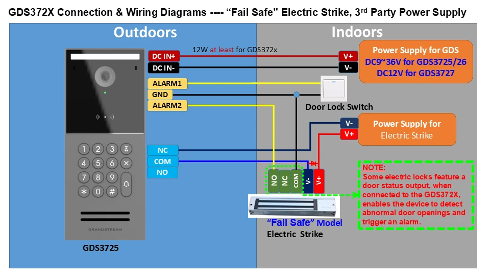
Diagram showing wiring for a 'Fail Safe' electric strike system with outdoor GDS3725 unit connected to indoor power supplies and a door lock switch.

“Fail Secure”  Electric Strike, 3rd Party Power Supply
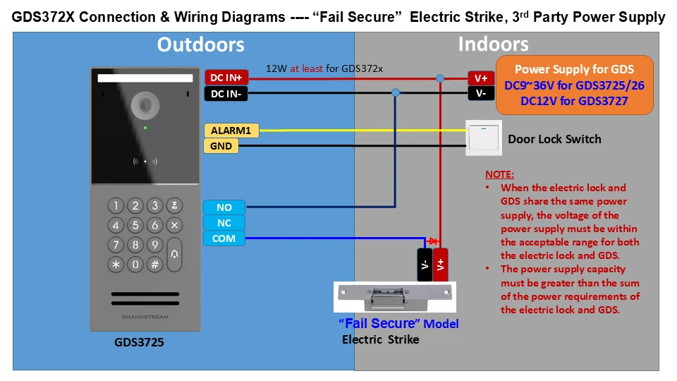
Diagram of GDS372X connection showing outdoors keypad wired to a fail-secure electric strike, with door lock switch, alarm, and a 12V power supply for indoor/outdoor sections.

“Fail Safe”  Electric Strike, POE Power Supply
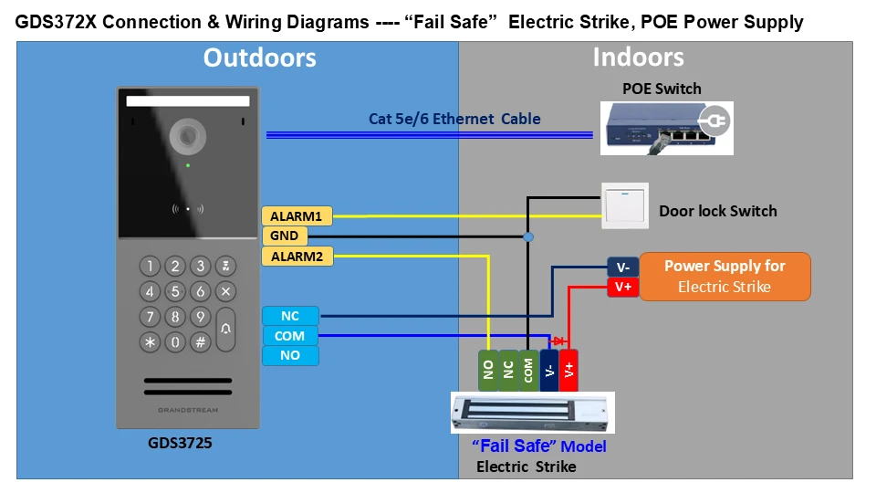
Outdoor GDS3725 keypad/controller wiring to indoor POE switch, door lock switch and fail‑safe electric strike.

Inappropriate Electric Strike Connection
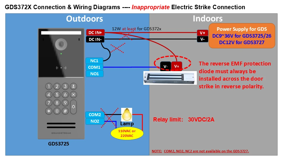
Diagram of GDS372X door access wiring: outdoors left shows keypad and DC input, indoors right shows power supply, V+/V-, and a relay to a lamp; notes about reverse EMF diode and relay limit.

Good Electric Strike & High-Power Device Connection
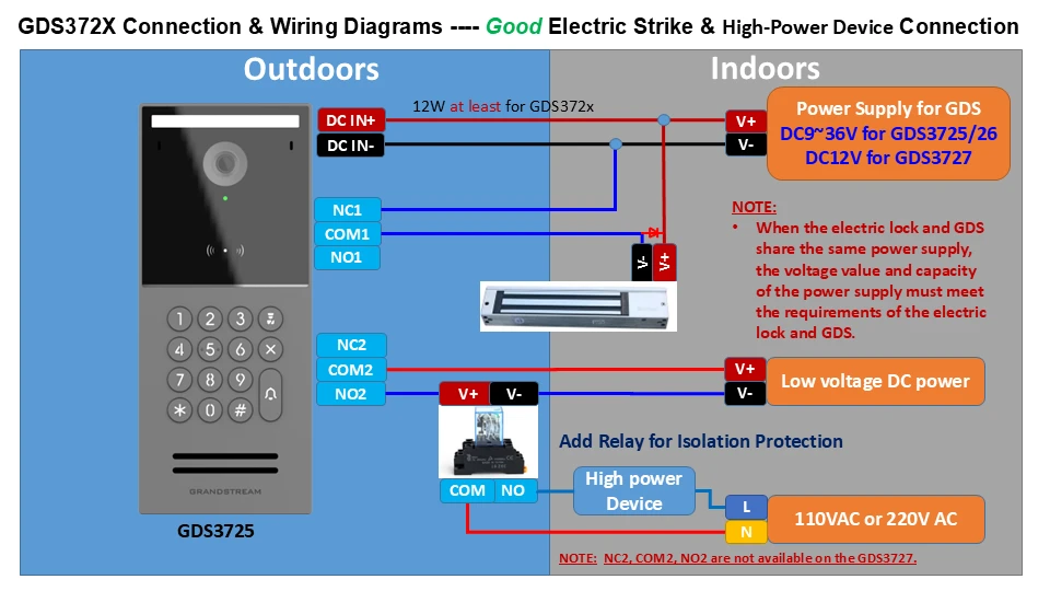
Wiring diagram for GDS372X door access: outdoor unit, indoor power supply, DC lines, NC/COM/NO relays, and lock control.

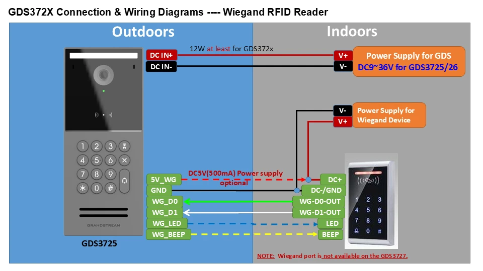
Wiegand RFID Reader

Diagram showing outdoor and indoor wiring for a GDS372X Wiegand RFID reader with power, data lines, and signal labels between reader and controller.

Dual GDS372X in Serial Control a Single Door (fail-safe)
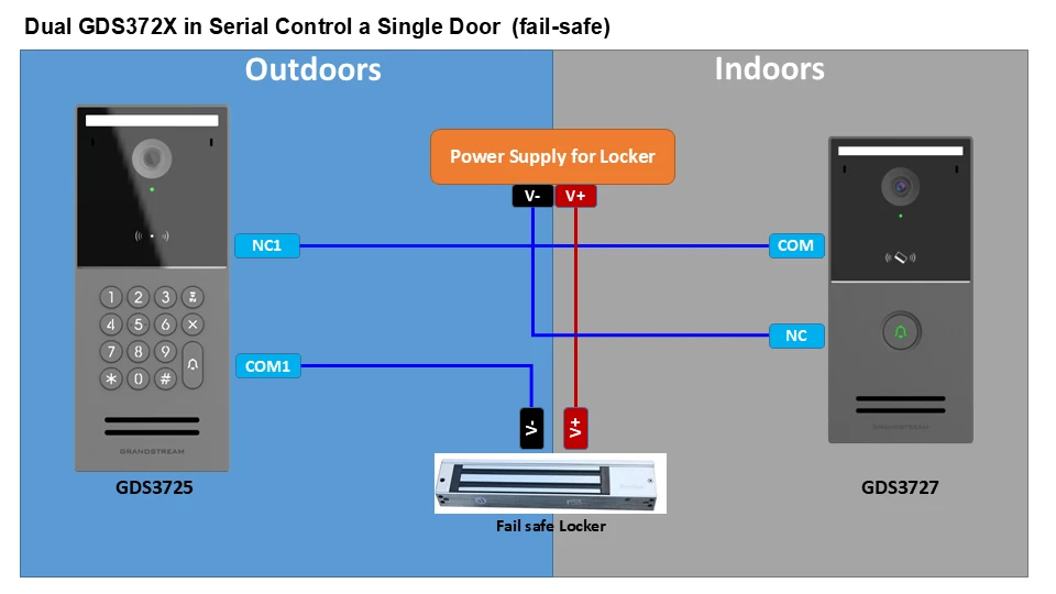
Diagram of Dual GDS372X door control: outdoor unit on left, indoor unit on right, with a fail-safe locker in the center and labeled NC/COM connections showing wiring between units and power supply/lock.

Dual GDS372X Control a Single Door (fail-safe) with Alarm

Locker with lock status output
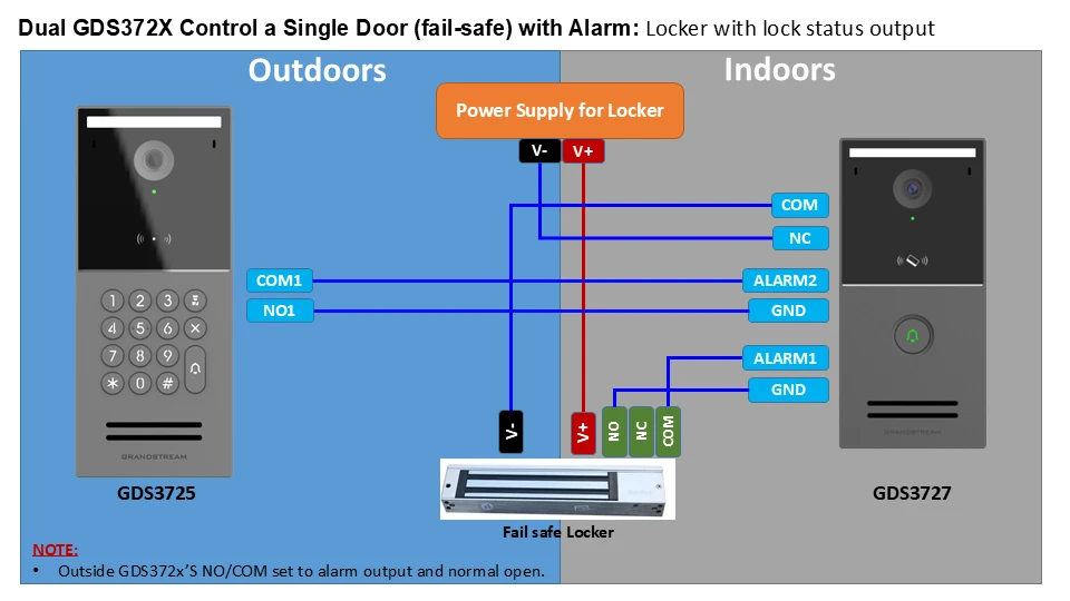
Wiring diagram for a dual GDS372X single-door fail-safe system with outdoor reader, indoor unit, power supply, and alarm outputs.

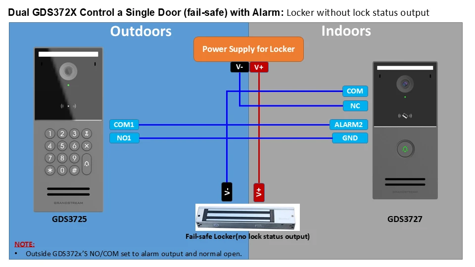
Locker without lock status output

Wiring diagram for a dual GDS372X door system: outdoor unit (GDS3725) connected to indoor unit (GDS3727) via a central power supply; shows V- and V+ to the locker, and signal lines to COM/NO1, COM/NC, ALARM2, and GND.

Was this article helpful?

Need Support?
Can’t find the answer you’re looking for? Don’t worry we’re here to help!
Contact Support