

GSC3570 Setup
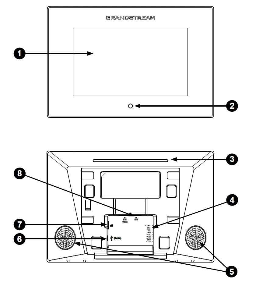
1 | Touch Screen | 5 | Speakers |
2 | Home Button | 6 | Micro USB |
3 | LED | 7 | Micro SD |
4 | 10-PIN Connector | 8 | LAN/PoE |
GSC3570 Ports
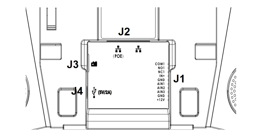
Jack | Port | Function | Remark | ||
Pin | Signal | Color | |||
J1 | 1 | COM1 | Orange | Alarm OUT | 1 Relay output, normal open or close, max 125VAC/0.5A or max |
2 | NO1 | Yellow | |||
3 | NC1 | Green | |||
4 | IN+ | White | Alarm IN (Active) | Alarm isolated input, for voltage signal detection, IN+ connect the | |
5 | GND | Black | Alarm GND | Voltage reference for IN+, Switch signal reference for AIN (1/2/3) | |
6 | AIN1 | Blue | Alarm IN (Passive) | Alarm input, for button/door contacts switch signal detection. | |
7 | AIN2 | Brown | |||
8 | AIN3 | Gray | |||
9 | GND | Black | Power Supply | DC12V recommend, input voltage rang 9-15V Current at least 1A@12V | |
10 | +12V | Red | |||
J2 | Network Port |
| Dual 10/100 Mbps Network ports: One is POE port with class AF | ||
J3 | Micro SD Port | Data storage | Support microSD/SDHC/SDXC, up to 256G | ||
J4 | Micro USB Port | Data exchange | Data exchange port, Not recommended to use this port to power supply. If needed, please use 5V/2A adapter. | ||