
WELCOME
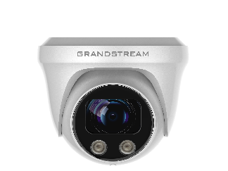
Thank you for purchasing Grand stream’s GSC3620 FHD IP Dome Camera, the innovative powerful weatherproof Vari-focal and Auto-Focus camera. The GSC3620 is a ceiling-mounted fixed dome IP camera with a 3.6mm lens – making it an ideal device for wide-angle monitoring of nearby subjects in environments such as banks, hotels, retail stores, offices, warehouses, and building entrances. GSC3620 supports motion detection and smart infrared technology for white balance and exposure to monitor activity at night in outdoor or dark enclosed spaces. The GSC3620 can be managed with GSURF Pro, Grandstream’s free video management software, along with other ONVIF-compliant video management systems. It pairs with Grandstream’s video phones and GSC3570 HD intercom and facility control station for active end-point monitoring and facility control. By adding weatherproof capabilities, this is an ideal device for increasing security and facility management in any indoor or outdoor area.
Designed for both indoor and outdoor environment, the GSC3620 IP Camera ensures ease of use, integration, and deployment, with multilingual graphical user interface, provides powerful solution to professional surveillance applications.
This manual will help you to learn how to operate and manage your GSC3620 FHD Infrared Weatherproof Vari-focal and Auto-Focus, Dome Camera, and make the best use of it.
PRODUCT OVERVIEW
Feature Highlights
The following table contains the major features of the GSC3620:
Table 1: GSC3620 Features in a Glance
GSC3620
|
|
GSC3620 Technical Specifications
The following table resumes all the technical specifications including the protocols/standards supported, voice codecs, telephony features, languages, and upgrade/provisioning settings for GSC3620.
Table 2: GSC3620 Technical Specifications
Network Protocol | SIP RFC3261, TCP/IP/UDP, RTP/RTCP, HTTP/HTTPS, ARP, ICMP, DNS (A record, SRV, NAPTR), DHCP, SSH, TFTP, NTP, STUN, LLDP-MED, TLS, SRTP |
Image Sensor Resolution | 1/2.7” CMOS Sensor, 2 megapixels (2MP), 1920(H)x1080(V) resolution |
Video Compression | H.264/JPEG/MJPEG |
Supported Maximum Video | Primary Stream: 1920×1080; 1280×960; 1280×720 Secondary Stream: 1280×720; 704×576; 640×480; 352×288; 320×240 |
Video Output | Network |
Audio | Line-In: 1 x 3.5mm, 1-50mVpp; Line-Out: 1 x 3.5mm, 560Ω, 4.0Vpp |
Scanning System | Progressive |
Image Configuration | Saturation, Brightness, Contrast, Sharpness, White Balance |
Focal Length | 2.8mm – 12mm Vari-Focal, Electronic Auto-Focus |
Infrared LED | 42μ x 2, up to 25M, Auto Control |
Ethernet | One RJ-45 (10/100Base-T) Port with PoE |
ONVIF | Yes, Profile S |
Day/Night | Color/ Black &White (IR-CUT) |
Motion Detection | Supported |
Language Supported | Multi-Language |
Privacy Mask | 4 Rectangular Zones |
Weatherproof Grade | Metal, IP67-level weatherproof capability |
Power | DC12V±10%,1A (Power Adapter NOT Included) PoE: Support IEEE 802.3af |
Temperature / Humidity | -20 °C ~ 60 °C, RH95% Max |
Weight and Dimensions | Unit: 714g, Dimension: 128 x 108 (LxH) mm; Package Weigh: 900g |
Compliance | FCC, CE, RCM, IC |
GETTING STARTED
This chapter provides basic installation instructions including the list of the packaging contents and also information for obtaining the best performance with the GSC3620.
Equipment Packaging
Table 3: Equipment Packaging – GSC3620
GSC3620 |
|

Powering and Connecting the GSC3620
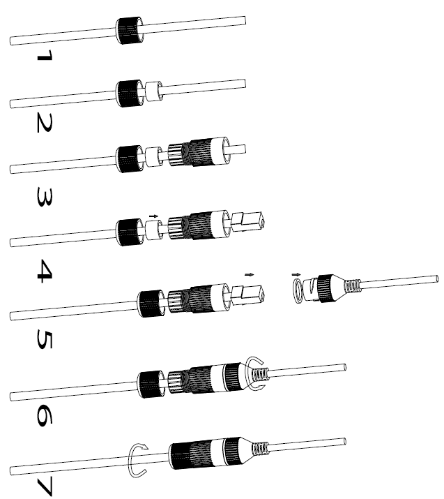
The GSC3620 can be powered either using the right PSU (DC12V, 1A) or using a PoE switch, please refer to illustration below to do the wiring and connect the waterproof RJ45 socket:
Option A (Recommended)
- Based on T-568B (see diagram below) to install the RJ45 plug, tighten the connector using the provided waterproof socket.
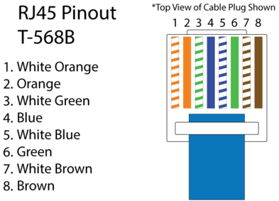
2. Connect other end of the cable into a switch supporting Power over Ethernet.
Option B
- Wire the cable and connect it to a network switch as in the figure above.
- Connect a 12VDC, 1A (minimum) Power Adapter (not provided) to the power socket of the GSC3620 tail cable. Make sure the polarity “+” (center) and “-” (outside) are correctly connected.
HARDWARE INSTALLATION
Mounting GSC3620

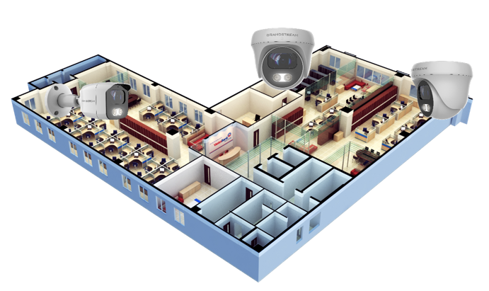
GSC3620 APPLICATION SCENARIOS
GSC3620 is very versatile infrared IP Camera, it can be used in a lot of scenarios.
LAN without Internet
For multi-room or a bigger space, multiple GSC3620 might be required. User can establish a local area network using PoE switch.
If remote access required, a router with internet access may add in.
Equipment List:
- Several GSC3620
- Ethernet cables
- Switch (Static IP required to configure to IP Cameras)
- PoE Switch (Optional, better solution)
Note: If remote access to the cameras required to view the LIVE video stream, then broadband Internet is required, and more equipment required: - Router (if DHCP configured than static IP is not required although still recommended)
- iPhone or Android phone. (Application like “IP Cam Viewer”)
LAN with Internet
For multi-room or a bigger space, with Internet access and local video recording required, following list is recommended:
Equipment List:
- Several GSC3620
- Ethernet cables
- Switch (PoE Switch recommended)
- Router
- Broadband Internet Access (FiOS, Cable or DSL)
- iPhone or Android phone. (Application like “IP Cam Viewer”)
- VMS GSurf_Pro Remote Access (Optional)

Application Peripheral Connection
Below is the illustration of GSC3620 peripheral connections for related application.
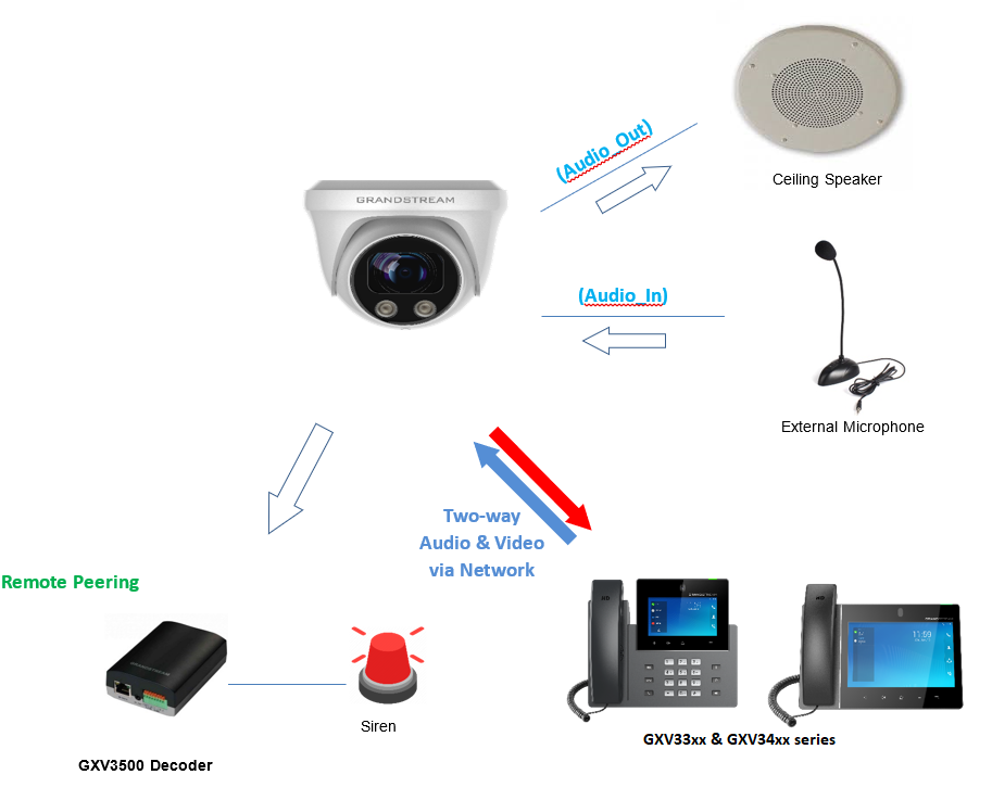
- Audio Output and Input using 3.5mm interface must match below parameters:
Audio Output | 3.5mm Line-Out, 560Ω, 4.0Vpp |
Audio Input | 3.5mm Line-In, 1-50mVpp |
- Grandstream phones can work with GSC3620 (video stream video phones GXV33xx & GXV34xx only) via either Peer IP (LAN) or SIP extension (WAN). Peer to Peer (or Direct IP) works only at LAN using static IP; SIP extension requires related SIP server/proxy provided and configured.
GSC3620 WEB GUI
Note the below requirement to access/configure the GSC3620:
- Internet Browser like Firefox, Chrome, Microsoft Internet Explorer.
- DHCP server enabled on the network.
Two ways exist for Windows user to get access to the GSC3620:
UPnP
By default, the GSC3620 has the UPnP feature turned ON. For customers using Windows network with UPnP turned on (most SOHO routers support UPnP), it is easy to access the GSC3620:
-
Find the “Network” icon
 on the windows Desktop.
- Click the icon to get into the “Network”, the GSC3620s will list as “Other Devices” shown. Refresh the pages if nothing displayed. Otherwise, the UPnP may not be active in the network.
- Click on the displayed icon of related GSC3620, the default browser (e.g.: Internet Explorer, Firefox, or Chrome) will open and connect directly to the login webpage.
GS Search
Double check the requirements then follow the below steps to access the GSC3620 WEB configuration page:
- Download and install GS Search tool from the link below:
Download GS_Search - Run the Grandstream GS_Search tool.
- Click on
 button to start device detection.
 - The detected devices will appear in the output field as below.
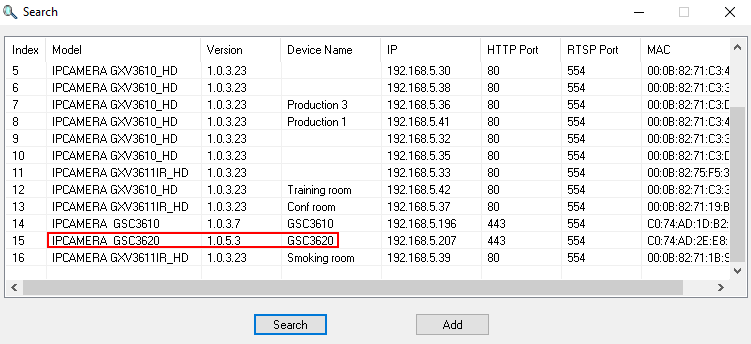
5. Double click on the detected device. The default browser (Chrome in this example) will open to display the camera’s login web interface.
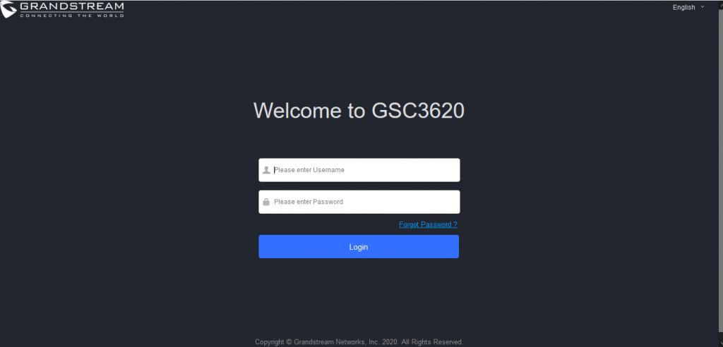
- When clicking on the “Language” drop down, supported languages will be displayed. Click to select the related webpage display language. (Current firmware supports only English as default and simplified Chinese).
6. Username and password are required to login the camera to manage the device.
The default username is “admin”; the default password is a random password printed in a sticker which can be found on the camera body or cable.
- The default connection is via HTTPS. Once input the correct username and password, the device configuration webpage will be available.
Web GUI Settings
The GSC3620 embedded Web server responds to HTTP/HTTPS GET/POST requests. Embedded HTML pages allow users to configure the application phone through a Web browser such as Microsoft’s IE, Mozilla, Firefox, Google Chrome and etc.
- Once logged in successfully to the GSC3620, the browser will display the GUI as shown below:
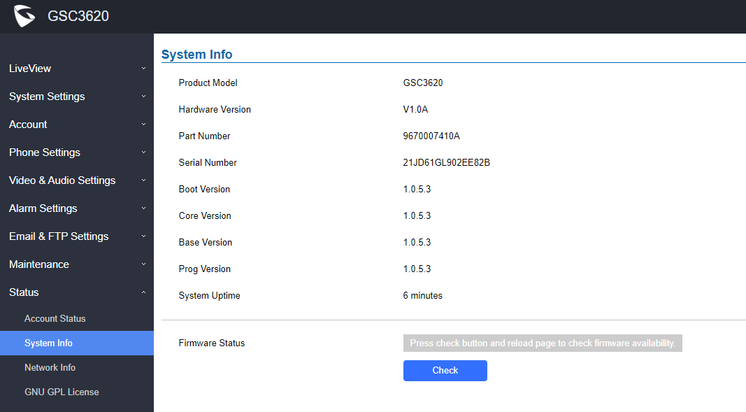
Table 4: GSC3620 WEB GUI Sections
Fields | Description |
LiveView | Access to live view stream page. |

| Play the primary stream. |

| Play the secondary stream. |
System Settings | Access to “System Settings” page. |
Account | Access to “Account” configuration page. |
Phone Settings | Access to “Phone Settings” configuration page. |
Video & Audio Settings | Access to “Video & Audio settings” page. |
Alarm Settings | Access to “Alarm settings” page. |
Email & FTP Settings | Access to “Email & FTP Settings” page. |
Maintenance | Access to “Maintenance” page. |
Status | Click to enter “Status” page. |
GSC3620 SETTINGS
Live View Page
This page allows users to view the live video of the GSC3620.
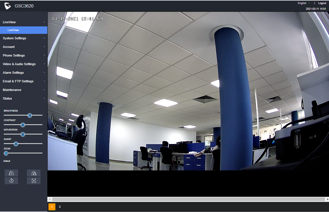
Two streams are available:
- Primary video stream: 1920*1080 resolution, recommended for continuous full HD recording
- Secondary video stream: 640*480 resolution, recommended for SIP/VoIP video calls
Vari-focal and Auto-Focus Settings
At the “LiveView” page, sliding the “ZOOM” bar left or right to zoom out/in the lens; click “Focus+/–“ to fine tune the focus; or click “One key focus” to let system auto-focus the scene; click “initialize lens” to go back to default.


Table 5: GSC3620/GSC362 Auto-Focus Settings Description
Fields | Description |

| Focus+ |

| Focus- |

| One Key Focus |

| Initialize Lens |
System Settings
This page allows users to configure date and time, network settings as well as access method to the GSC3620 and password for accessing the Web GUI.
Date & Time Settings
This page allows users to adjust system date and time.
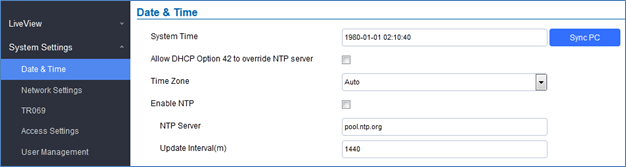
System Time | Displays the current system time. |
Defines whether DHCP Option 42 should override NTP server or not. When enabled, DHCP Option 42 will override the NTP server if it is set up on the LAN. The default setting is “Yes”. | |
Sync PC | Clicks to synchronize current time with the computer. |
Time Zone | Selects from drop down menu the preferred time zone. Default is “Auto” |
Enable NTP | Enables NTP to synchronize device time. |
NTP Server | Configures the domain name of NTP server. Default is “pool.ntp.org” |
Update Interval | Configures the Interval (in minutes) to retrieve updates from the NTP server. |
Network Settings
This page allows users to set either a static or DHCP IP address to access the unit.
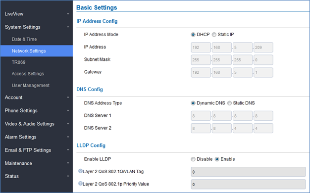
IP Address Mode | Selects DHCP or Static IP. Default DHCP. (Static recommended) |
IP Address | Configures the Static IP of the GSC3620. |
Subnet Mask | Configures the Associated Subnet Mask. |
Gateway | Configures the Gateway IP address. |
DNS Address Type | Specifies the DNS type used: Dynamic DNS or Static DNS. |
DNS Server 1 | Configures DNS Server 1 IP address. |
DNS Server 2 | Configures DNS Server 2 IP address. |
Controls the LLDP (Link Layer Discovery Protocol) service. The default setting is “Enabled”. | |
Assigns the VLAN Tag of the Layer 2 QoS packets. Default value is 0. | |
Layer 2 QoS 802.1p Priority Value | Assigns the priority value of the Layer2 QoS packets. Default value is 0. |
TR069
This page allows users to set TR-069.
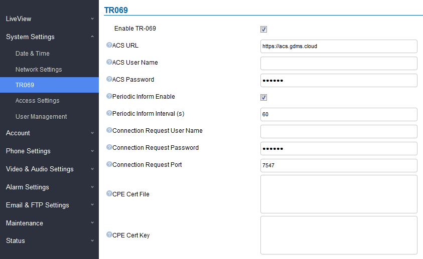
This feature allows centralized management and provisioning of mass product operations. This is very useful for ITSP customers and enterprise solutions. With GDMS management, customers can manage, provision the GSC3620 from GDMS platform.
For detailed management and usage of this feature, please refer to Grandstream Device Management System (GDMS) product page: http://www.grandstream.com/products/device-management/gdms
Table 6: TR069 Settings
ACS URL | Specifies URL of TR-069 ACS (e.g.,http://acs.mycompany.com), or IP address. Default setting is “https://acs.gdms.cloud” |
TR-069 Username | ACS username for TR-069. |
TR-069 Password | ACS password for TR-069. |
Periodic Inform Enable | Enables periodic inform. If set to “Yes”, device will send inform packets to the ACS. |
Periodic Inform Interval | Sets up the periodic inform interval to send the inform packets to the ACS. The default value is “60”. |
Connection Request Username | The username for the ACS to connect to the phone. |
Connection Request Password | The password for the ACS to connect to the phone. |
Connection Request Port | The port for the ACS to connect to the phone. The default value is “7547”. |
CPE Cert File | The Cert File for the phone to connect to the ACS via SSL. |
CPE Cert Key | The Cert Key for the phone to connect to the ACS via SSL. |
Access Settings
This page configures the GSC3620 access control parameters.
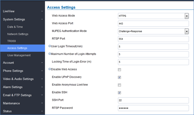
Web Access Mode | Selects the access mode to the Web GUI either HTTP or HTTPS. |
Web Access Port | Specifies the TCP port for Web Access, default 443. |
Allows 3rd party system integrator or developers to implement related application for users. By default, this feature is disabled and use more secured “Challenge+Response” mode. If enabled, user can send HTTP API with correct credentials to retrieve MJPEG video stream or JPEG snapshot from GSC. Notes:
HTML based 🡺 http(s)://admin:password@IP_GSC3620:Port/jpeg/mjpeg.html Stream 🡺 http(s)://admin:password@ip:port/jpeg/stream
| |
RTSP Port | Specifies RTSP port for media stream, default TCP port 554. |
User Login Timeout(min) | If no action is made within this time the GSC3620 will logout from the Web GUI, range is between 3 and 60. Default is 5. |
Maximum Number of Login Attempts | Specifies the allowed login times error limit, if the unsuccessful login attempts exceed this value, the GSC3620 webGUI will be locked for the time specified in Login Error Lock Time. Default is 5. |
Locking Time of Login Error (m) | Specifies how long the GSC3620 is locked before a new login attempt is allowed. Default is 5. |
Allow or deny the web access to the GSC3620. (HTTP API do not take effect when this option is enabled). Note: If both WebUI and SSH are disabled, GSC3620 will get blocked and not be able to be accessed. Only two ways to get it back:
| |
Enable UPnP Discovery | UPnP (or mDNS) function for local discovery. Default setting is enabled. |
1. When enabled, user can display the camera stream from without admin credentials using the following URL scheme: http(s)://GSC3620_IP:port/videoview.html
http(s)://IP:port/anonymous/snapshot/view.html Or with: https://IP_GSC3620:Port/anonymous/snapshot/view.jpg
| |
Allows SSH access for remote secured configuration purposes (restart, upgrade, provision…) | |
Specifies the SSH port. Default setting is 22. | |
RTSP Password | This password can be used for RTSP stream display. |
Retrieving Video Streams
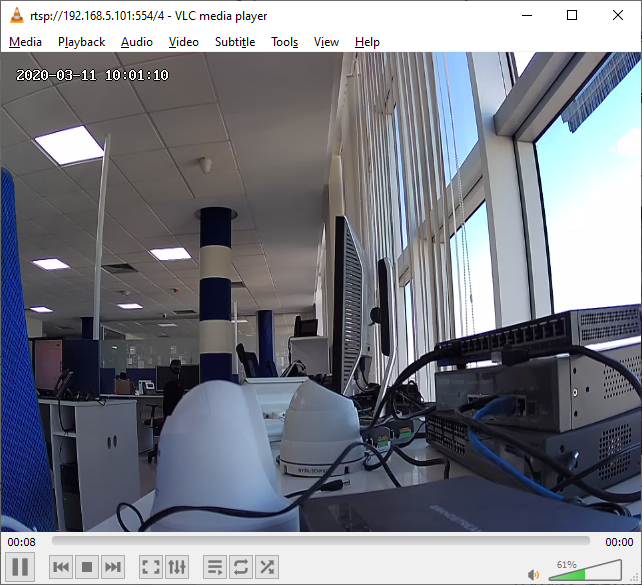
RTSP Stream
To retrieve video stream via RTSP, users can use the following format:
rtsp://admin:password@IP_GSC3620:Port/X where X=0,4 for 1st, 2nd streams respectively
The GSC3620 supports MJPEG Stream live viewing via HTTP API commands, this can be used without installing the Live view browser plugin. Users can deploy two methods to retrieve MJPEG stream depending on MJPEG Authentication Mode, which can be set under following path:
Web UI 🡺 System Settings 🡺 Access Settings
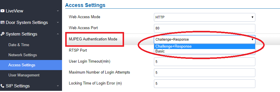
A. “Challenge+Response” MJPEG Authentication Mode:
In order to get live view stream using MJPEG stream over HTTP command on this mode, please fellow below steps:
- In browser type in http(s)://IP_Address_GSC3620:Port/jpeg/mjpeg.html
Example: https://192.168.5.146/jpeg/mjpeg.html - The browser will pop up the window above asking for credentials, user needs to enter admin credential.
- The browser will show MJPEG stream (720p).
B. “Basic” MJPEG Authentication Mode:
Please follow below steps in order to take a snapshot via HTTP commands:
-
In browser type in: http(s)://admin:password@IP_Address_GSC:Port/jpeg/mjpeg.html
Example: https://admin:admin@192.168.5.157:443/jpeg/mjpeg.html - The browser will show MJPEG stream (720p).
User Management
This page allows users to configure the password for administrator. Since this is a door system which must be a secure product, the use is only limited to administrator.
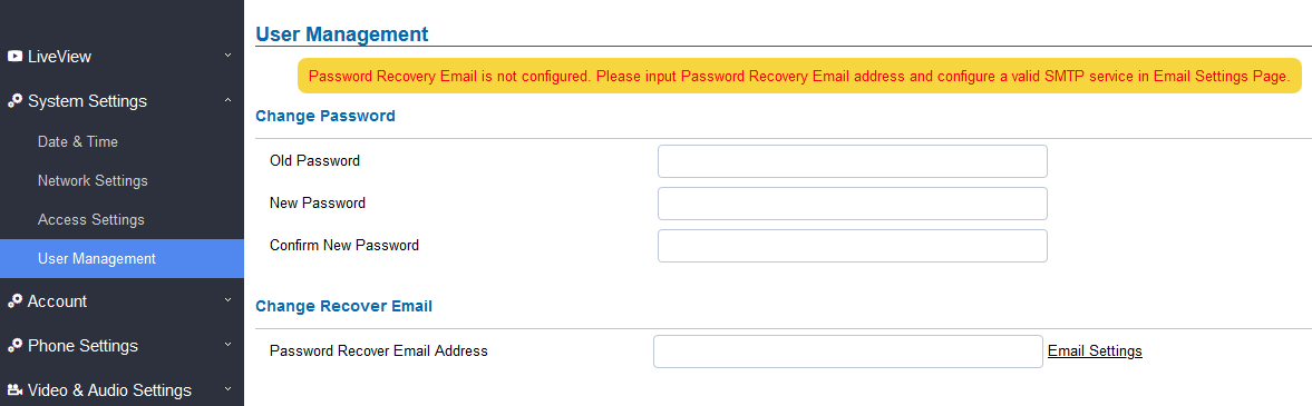
Old Password | Old password must be entered to change new password. |
New Password | Fill in the revised new password in this field. |
Confirm User Password | Re-enter the new password for verification, must match. |
Password Recovery Email Address | This option is highly recommended, as if the password is lost, you can recover it on the configured Email address. Note: Make sure to configure SMTP Email Settings under “Email Settings” |
Account
The GSC3620 supports 4 SIP accounts and 4 lines, this section covers the configuration of basic and advanced sip settings for each account.
Account 1 – 4
This page allows the administrator to configure the SIP account basic and advanced settings for each SIP account:
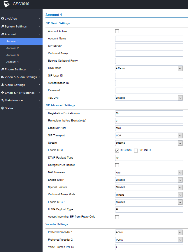
Table 9: SIP Account Basic & Advanced Settings
SIP Basic Settings | |
Account Active | This field indicates whether the account is active. Default setting is “Yes”. |
Account Name | Configures the SIP account name used for identification. |
SIP Server | Configures the FQDN or IP of the SIP server from VoIP service provider or local IPPBX. |
Outbound Proxy | Configures the IP address or the domain name of the outbound proxy, media gateway, or session border controller. It is used by the GSC for firewall or NAT penetration in different network environments. If a symmetric NAT is detected, STUN will not work and only an outbound proxy can provide a solution. |
Backup Outbound Proxy | Configures the backup outbound proxy to be used when the “Outbound Proxy” registration fails. By default, this field is left empty. |
Configure which DNS mode will be used to translate the SIP Server FQDN (Default value is A Record):
| |
Configures the SIP username or telephone number from ITSP. Note: Letters, digits and special characters including @ are supported. | |
Authenticate ID | Configures the Authenticate ID used by SIP proxy. |
Sets the Authenticate password used by SIP proxy. Note: For security reasons, the SIP password is invisible on the web UI. | |
TEL URI | Select “User=Phone” or “Enabled” from the dropdown list. If the SIP account has an assigned PSTN telephone number, this field should be set to “User=Phone”. Then a “User=Phone” parameter will be attached to the Request-Line and “TO” header in the SIP request to indicate the E.164 number. If set to “Enable”, “Tel:” will be used instead of “SIP:” in the SIP request. The default setting is “Disable”. |
SIP Advanced Settings | |
Registration Expiration (m) | Sets the registration expiration time. Default setting is 60 minutes. Valid range is from 1 to 64800 minutes. |
Specifies the time frequency (in seconds) that the GSC3620 sends re-registration request before the Register Expiration. The default value is 0. Range is from 0-64800 seconds. | |
Local SIP Port | Sets the local SIP port. Default setting is 5060 for Account 1, 5062 for Account 2, 5064 for Account 3, 5066 for Account 4. |
SIP Transport | Chooses the SIP transport protocol. UDP, TCP or TCP/TLS. Default setting is UDP. |
Stream | Select the Video stream to be used by the GSC3620 when call is made from this SIP Account. Default is Stream 2. |
Specifies the mechanism to transmit DTMF digits. There are 2 supported modes:
| |
Configures the payload type for DTMF using RFC2833. Default value is 101. Range: 96~127. | |
Unregister on Reboot | Allows the SIP user’s registration information to be cleared when the GSC reboots. The SIP REGISTER message will contain “Expires: 0” to unbind the connection. |
This parameter configures whether the NAT traversal mechanism is activated. Users could select the mechanism from No, STUN, Keep-alive, UPnP, Auto. The default setting is “No”. If set to “STUN” and STUN server is configured, the GSC will route according to the STUN server. If NAT type is Full Cone, Restricted Cone or Port-Restricted Cone, the unit will try to use public IP addresses and port number in all the SIP&SDP messages. The GSC will send empty SDP packet to the SIP server periodically to keep the NAT port open if it is configured to be “Keep-alive”. Configure this to be “No” if an outbound proxy is used. “STUN” cannot be used if the detected NAT is symmetric NAT. If the firewall and the SIP device behind the firewall are both able to use UPNP, it can be set to “UPNP”. Both parties will negotiate to use which port to allow SIP through. | |
Enable SRTP mode based on your selection from the drop-down menu. The default setting is “Disabled”, the two other modes are “Enabled but Not Forced” and “Enabled and Forced”. | |
Configures GSC settings to meet different vendors’ server requirements. Users can choose from Standard, BroadSoft or Telefonica Spain. The default setting is “Standard”. | |
In route: outbound proxy FQDN is placed in route header. This is used for the SIP Extension to notify the SIP server that the device is behind a NAT/Firewall. Always sent to: SIP messages will always be sent to Outbound proxy. Not in route: remove the Route header from SIP requests. | |
This option allows 3rd party Service Provider or Cloud Solution to monitor the operation status of the GSC3620 by using related SIP Calls. By default, it is disabled. Users can choose either RTCP or RTCP-XR. | |
The H.264 payload type can now be configured to be compatible with 3rd party video phones, as well as other advanced SIP settings, to easy system integration process. Default is 99. | |
When set to “Yes”, the SIP address of the Request URL in the incoming SIP message will be checked. If it does not match the SIP server address of the account, the call will be rejected. The default setting is disabled. | |
Vocoder Settings | |
Select audio codec to prioritize. Supported codecs are: PCMU and PCMA. | |
Preferred Vocoder 2 | Select the second audio codec PCMU or PCMA. |
Configures the number of voice frames transmitted per packet. When configuring this, it should be noted that the “ptime” value for the SDP will change with different configurations here. This value is related to the codec used and the actual frames transmitted during the in-payload call. For end users, it is recommended to use the default setting, as incorrect settings may influence the audio quality. Range is from 1-64. The default setting is 2. |
Phone Settings
The phone settings allow users to configure the GSC3620 phone settings and the White list for all the SIP accounts.
Phone Settings
This page allows users to configure the GSC3620 phone settings.
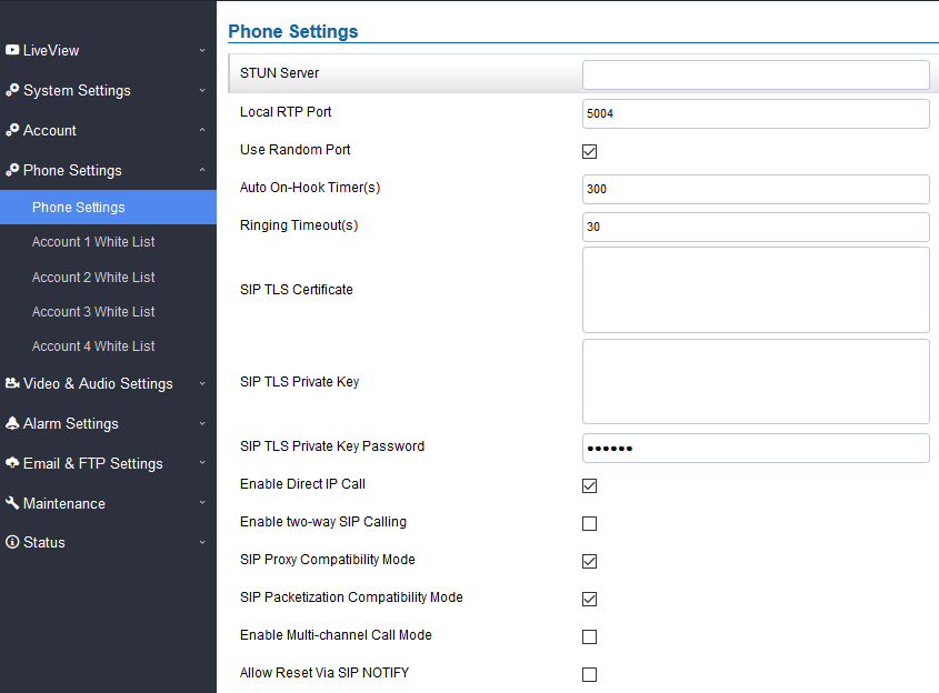
STUN Server | Configures the STUN server FQDN or IP. If the device is behind a non-symmetric router, STUN server can help to penetrate & resolve NAT issues. |
Local RTP Port | Sets the local RTP port for media. Default setting is 5004. Range between 1024~65400. |
Forces the GSC3620 to use random ports for both SIP and RTP messages. This is usually necessary when multiple units are behind the same full cone NAT. The default setting is “Disabled” Note: This parameter must be set to “Disabled” for Direct IP Calling to work. | |
Auto On-Hook Timer | Configures the auto on-hook timer (in seconds) for automatic disconnecting the SIP call. Default setting is 300. Range between 0~65535. |
Specifies the Ring timeout, when no reply is returned from the called party after exceeding this field, the GSC3620 will hang up the call. The value is in the range of 0s – 90s. By default, it is “30” seconds. | |
SIP TLS Certificate | Input the TLS certificate here for encryption. |
SIP TLS Private Key | Input private key here for TLS security protection. |
SIP TLS Private Key Password | Specifies the password for SIP TLS private Key. |
Enable Direct IP Call | Accepts peer-to-peer IP call (over UDP only) without SIP server. Default is “Enabled”. |
Allows the user to enable/disable the alarm sound during a SIP call triggered by doorbell pressing. | |
SIP Proxy Compatibility Mode | Enables more proxy compatibility with cost of bandwidth, the SIP call will send audio no matter what. |
When enabled, the GSC3620 will have in SDP “packetization-mode = 0”. This is required when the device is interacting with legacy video phones that only accepts this value to decode the RTP. | |
This feature allows the device to receive multiple calls at the same time, with one active and others on hold (up to 4 calls maximum). | |
Allows to factory reset the devices directly through SIP Notify. If “Allow Reset Via SIP NOTIFY” is “check”, then once the GSC3620 receives the SIP NOTIFY from the SIP server with Event: reset, the device will perform a factory reset after authentication. This authentication can be either with:
Default is unchecked (disabled). |
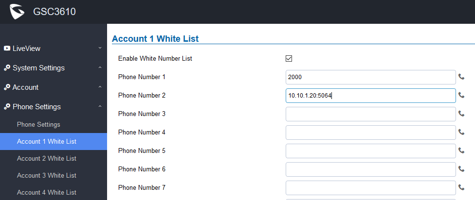
Account [1-4] White List
This page allows users to configure the white list per account, which is a phone number or extension list that can call the GSC3620. (The call will be automatically answered when calling from a phone set on the white list, and all other inbound calls will be blocked), the user can configure up to 30 white phone numbers per SIP account. Moreover, besides numbers associated to active cards, and numbers on the “Number Called When Doorbell Pressed” setting, all whitelisted numbers can open door remotely by using the respective PIN code.
The table below gives a brief overview of the options:
Enable White Number List | Enables the White List feature. |
Phone Number 1 -30 | Adds a new phone number (or IP address) to the white list. Notes:
|
Video & Audio Settings
The audio and videos settings allow users to configure the video / audio codecs, videos resolution, CMOS settings and audio related settings.
Video Settings
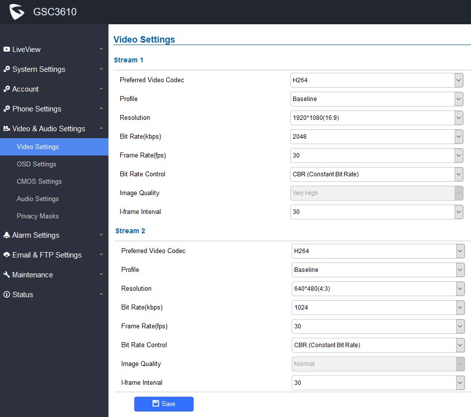
Stream 1 | |
Preferred Video Codec | Selects the videos codecs, the codecs supported are H.264 MJPEG. Default setting is H.264. |
Profile | Selects the H.264 profile. Three profiles are available for H.264: Baseline, Main Profile and High Profile. |
Resolution | Specifies the resolution in pixels used at video image. |
Bit Rate(kbps) | Selects the video bitrate or bandwidth used. |
Frame Rate(fps) | Selects the maximum frame rate used (more data if big frame used). |
Bit Rate Control | Selects the constantly bit rate, or variable bit rate. |
Image Quality | Selects the image quality used when Variable Bit Rate used. |
I-frame Interval | Configures the I-frame interval (suggested 2~3 times of frame rate). |
Stream 2 | |
Preferred Video Codec | Selects the videos codecs, the codecs supported are H.264 and MJPEG. Default setting is H.264. |
Profile | Selects the H.264 profile. Three profiles are available for H.264: Baseline, Main Profile and High Profile. |
Resolution | Specifies the resolution in pixels used in the video image. |
Bit Rate(kbps) | Selects the video bitrate or bandwidth used. |
Frame Rate(fps) | Selects the maximum frame rate used (more data if big frame used). |
Bit Rate Control | Selects the constant bit rate, or variable bit rate. |
Image Quality | Selects the image quality used when Variable Bit Rate used. |
I-frame Interval | Configures the I-frame interval (suggested 2~3 times of frame rate). |
OSD Settings
OSD Settings (On Screen Display) allow the users to Display timestamp and text on the video screen.
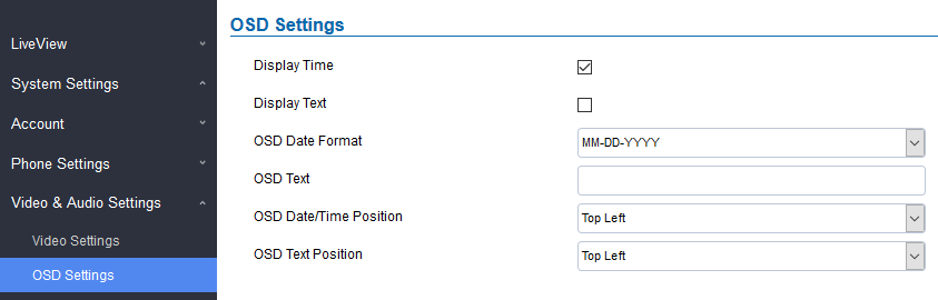
Display Time | When checked, time will be displayed inside the video image. |
Display Text | When checked, inputted text on “OSD Test” will be displayed on the video image. |
OSD Date Format | Select the date format from drop down list. |
OSD Text | Input a text (to identify the GSC3620) it will be shown on the screen. |
OSD Date/Time Position | Show the Date/Time position on the screen. |
OSD Text Position | Show the text position on the screen. |
CMOS Settings
This page configures the CMOS parameters for different scenarios.
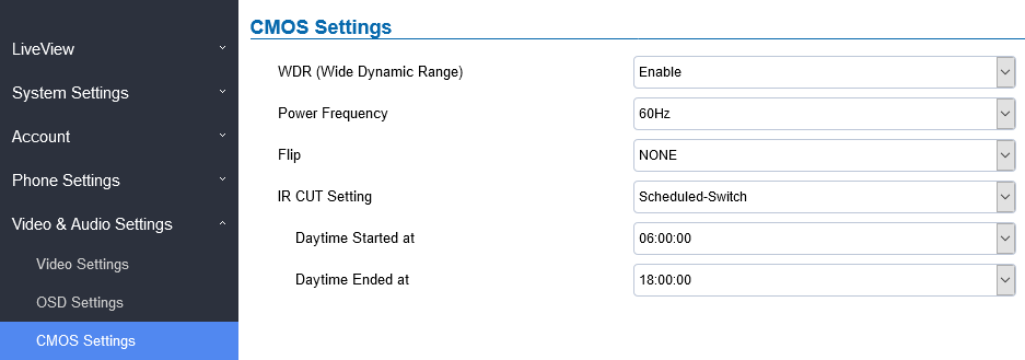
WDR (Wide Dynamic Range) | Enable or Disable the Wide Dynamic Range fature. Default “Enable”. |
Power Frequency | Select correct light condition for the scene monitored: 50Hz power frequency (Europe, China, etc.) or 60Hz power frequency (US, Japan, etc.). |
Flip | Pull down to choose to flip video either vertically, horizontal or both |
IR CUT Setting | Manual: User can set manually The Daytime/Night Model to either Daytime or Night. Automatic: The Camera will automatically switch to either Daytime or Night depending on light condition. Scheduled-Switch: The user can configure Daytime schedule by editing both “Daytime Started at” and “Daytime Ended at” fields. Default is Automatic. |
Audio Settings
This page allows users to configure the audio settings.
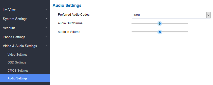
Preferred Audio Codec | Configures the audio codec. Two codecs are available: PCMU and PCMA. |
Adjusts the speaker volume connected. | |
Adjusts the Mic volume. |
Privacy Masks
This page allows users to configure privacy masks up to 4 different regions by selecting different regions requiring privacy mask as displayed on the following figure. When privacy mask enabled, the video at related region will be masked by black color and no video displayed inside that mask.
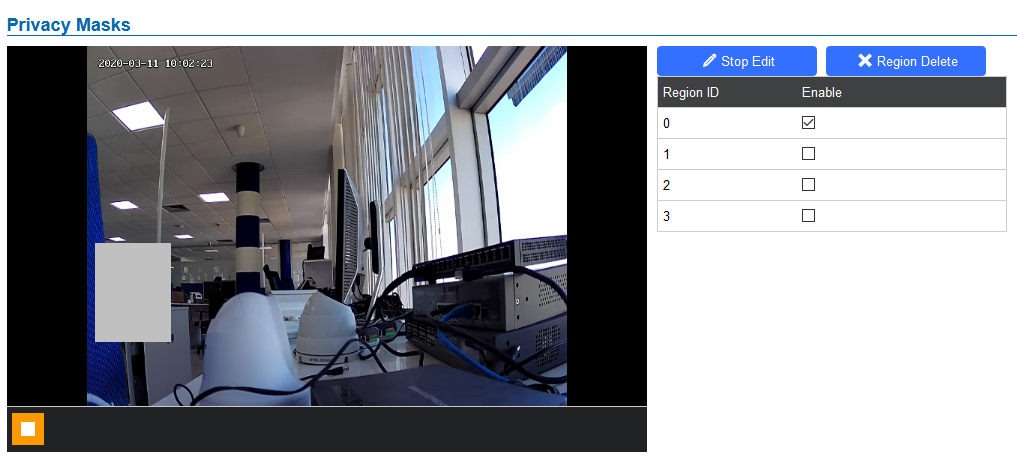
- Click “Start Edit” then long press and slide to identify a region
- Select a preconfigured region then Click “Region Delete” to remove it.
Alarm Settings
This page allows users to configure alarm schedule and alarm actions.
Alarm Events Config
This page allows users to configure GSC3620 events to trigger programmed actions within predefined schedule.
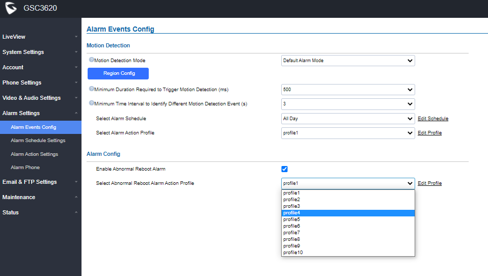
Table 16: Alarm Events Config Settings
Motion Detection Mode |
|
Maximum Time to Identify a Valid Multi-Zone Alarm Detection | If all preset zones have triggered an alarm within the configured time (in Seconds), this will be considered as a valid alarm/event, otherwise it will be an invalid alarm. |
Minimum Number of Alarming Zones for a Valid Multi-Zone Alarm Detection | If set multi-zone alarm, when the number of detection zones where alarm triggered reaches the configured number, it is considered a valid alarm/event, otherwise it will be an invalid alarm. For example, the value is set 3 with total of 4 zones, when zones with triggered alarm get to 3, a valid alarm/event will be reported. |
Minimum Number of Blocks Per Region to Trigger Detection | The threshold is the ratio of single small squares compared to the whole alarm zone, alarm will trigger when the ratio reached. |
Minimum Duration Required to Trigger Motion Detection (ms) | The time when an object moving in the preset zone is longer than the configured duration, this is considered a valid alarm/event, otherwise it is invalid alarm/event. |
Minimum Time Interval to Identify Different Motion Detection Event (s) | This minimum time interval is used to identify different motion detection events. If two consecutive motion detection alarm events occurred within this time interval, they will be considered as the same motion event. Otherwise they will be considered as two different motion events. |
Motion Detection
Users can select a specific region to trigger the alarm using motion detection.
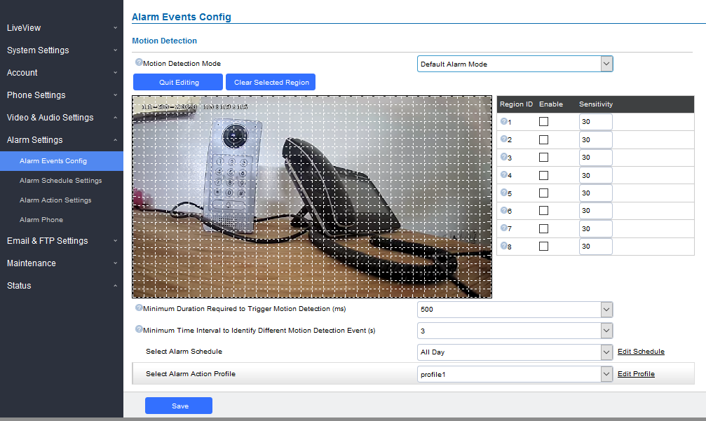
Region Config | Configures the motion detection region. First click to access the Region Config menu and second click to quit. |
Clear Selected Region | Selects a zone on the screen then click on “Clear” to delete the region. |
Sensitivity | Specifies the region sensitivity (value between 0-100%). |
Select Alarm Schedule | Selects the alarm schedule. |
Select Alarm Action Profile | Selects the programmed Alarm Action profile. |
Alarm Config
This page specifies the configuration of Abnormal Reboot Alarm Action.
Enable Abnormal Reboot Alarm | When checked, the IPC will sent an email if there is a power outage, which could affect the Auto-Focus as the AF might be affected after this power failure causing all the later on recording to become unclear. Thus the email will help the administrator to login and take corrective actions. |
Select Abnormal Reboot Alarm Action Profile | If all preset zones have triggered an alarm within the configured time (in Seconds), this will be considered as a valid alarm/event, otherwise it will be an invalid alarm. |
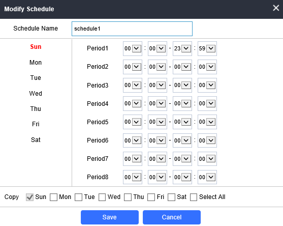
Alarm Schedule Settings
This page specifies the configuration of Alarm Schedule.
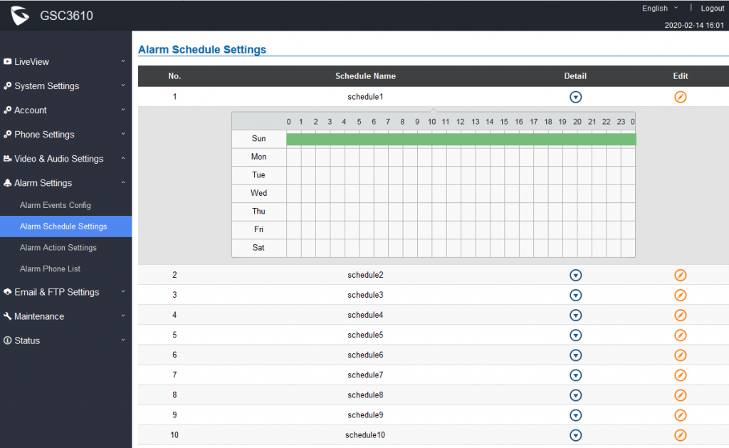
GSC3620 supports up to 10 alarm schedules to be configured, with time span specified by users. Users can View the schedule details by clicking
![]() or Edit the alarm schedule by clicking
or Edit the alarm schedule by clicking
![]() button.
button.
Usually the 24 hours’ span is 00:00 ~ 23:59, which is 24 hours’ format. Note that it is possible to copy the configuration to different date during the schedule programming using the banner at the bottom.
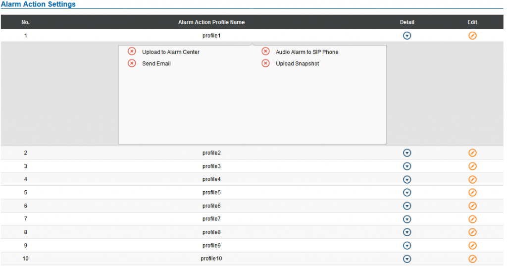
Alarm Action Settings
This page specifies the configuration of Profile used by the Alarm Actions. A Profile is required before the Alarm Action can take effect.
User can edit the alarm action by clicking
![]() button, the following window will popup.
button, the following window will popup.
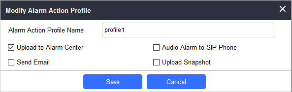
Upload to Alarm Center | If selected, the GSurf will popup alarm window and sound alarm in the computer speaker. |
Audio Alarm to SIP Phone | If selected, GSC3620 will call pre-configured (video or audio) phone and will play sound alarm. |
Send Email | If selected, an email with snapshot will be sent to the pre-configured email destination. |
Upload Snapshot | If selected, snapshots at the moment where the event is triggered will be sent to preconfigured destination (e.g.: FTP or email). |
Alarm Phone List
This page allows users to configure the Alarm Phone List, which are phone numbers or extensions list that the GSC3620 will call out when event is trigged.
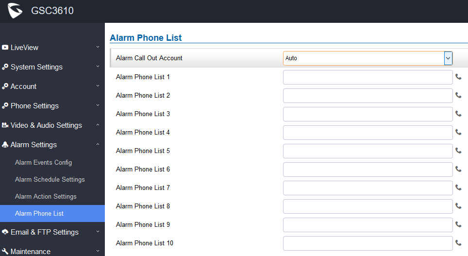
Alarm Call Out Account | Select the SIP Account to be used by the GSC3620 when alarm out is triggered. |
Alarm Phone List 1-10 | Add or delete number from the phone alarm list. (When IP address is used then the port needs to be appended, example: 192.168.1.12:5060). |
Once the event is triggered the GSC3620 will call the first number, once time out is reached and no answer is returned from the first number, the GSC3620 will try the next number on the list and so on. Once the remote phone answers the call, an alarm will be played to notify users that an event is triggered.
Email & FTP Settings
This page contains Email and FTP Settings.
Email Settings
This page allows users to configure email client to send out an email when the alarm is trigged.
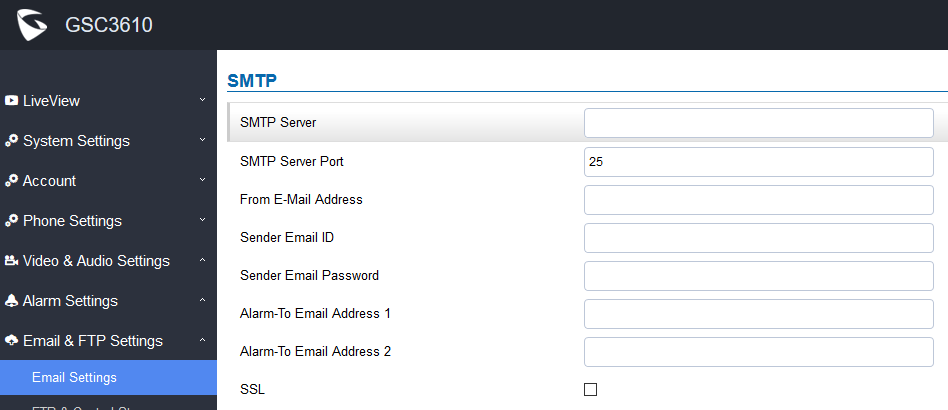
Table 20: Email Settings – SMTP
SMTP Server | Configures the SMTP Email Server IP or Domain Name. |
SMTP Server Port | Specifies the Port number used by server to send email. |
From E-mail address | Specifies email address of alarm email sending from, usually client email ID. |
Sender Email ID | Specifies sender’s User ID or account ID in the email system used. |
Sender Email Password | Specifies sender’s password of the email account. |
Alarm-To Email Address 1 | Specifies the 1st email address to receive the alarm email. |
Alarm-To Email Address 2 | Specifies the 2nd email address to receive the alarm email. |
SSL | Check if the SMTP email server requires SSL. |
Notes:
- Click “Save” to save the email configuration information.
-
Click “Email Test” after configuration, if settings are correct, a test email will send out and “E-mail test successfully” message on the top page will appear.

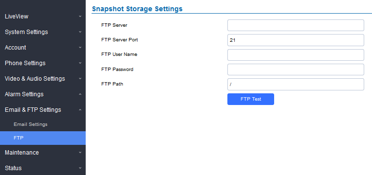
FTP & Center Storage
This page allows users to configure the FTP Settings in order to upload capture images.
Table 21: Picture Storage Settings
FTP Server | Configures the IP address of the FTP server when selected to upload images to. |
FTP Server Port | Specifies the FTP address port. |
FTP Username | Specifies the FTP server account name. |
FTP Password | Specifies the FTP server password. |
FTP Path | Specifies the storage path. |
FTP Test | Click to test the connection with FTP server. |
Maintenance Settings
This page shows the GSC3620 Maintenance parameters.
Upgrade
This page contains the upgrade and provisioning parameters of the GSC3620.
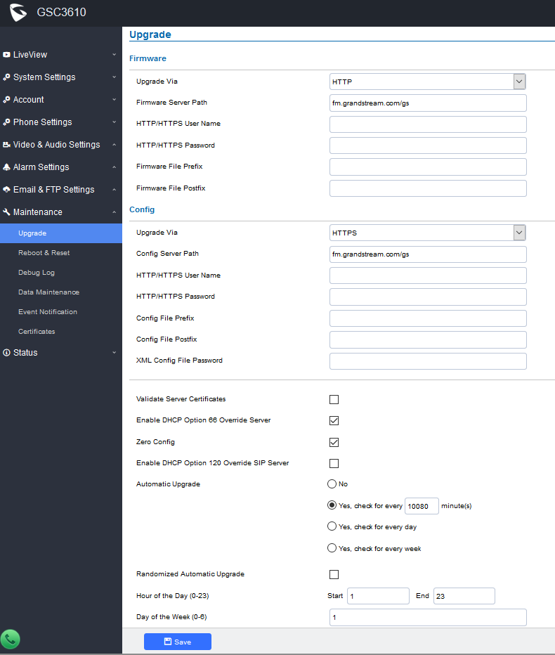
Firmware | |
Upgrade Via | Selects the upgrade method (TFTP, HTTP, or HTTPS). |
Firmware Server Path | Configures the IP address or the FQDN of the upgrade server. |
HTTP/HTTPS Username | The username for the HTTP/HTTPS server. |
HTTP/HTTPS Password | The password for the HTTP/HTTPS server. |
Firmware File Prefix | Enables your ITSP to lock configuration updates. If configured, only the firmware file with the matching encrypted prefix will be downloaded and flashed into the phone. |
Firmware File Postfix | Enables your ITSP to lock firmware updates. If configured, only the firmware with the matching encrypted postfix will be downloaded and flashed into the phone. |
Config | |
Upgrade via | Selects the upgrade method (TFTP, HTTP, and HTTPS). |
Config Server Path | Configures the IP address or the FQDN of the configuration server. |
HTTP/HTTPS Username | The username for the HTTP/HTTPS server. |
HTTP/HTTPS Password | The password for the HTTP/HTTPS server. |
Config File Prefix | Enables your ITSP to lock configuration updates. If configured, only the configuration file with the matching encrypted prefix will be downloaded and flashed into the phone. |
Config File Postfix | Enables your ITSP to lock configuration updates. If configured, only the configuration file with the matching encrypted postfix will be downloaded and flashed into the phone. |
XML Config File Password | Specifies the password for the configuration file. |
Validate Server Certificate | Enable this option in order to validate certificate with trusted ones during TLS connection. |
Enable DHCP Option 66 Override Server | Activates DHCP option 66 to override upgrade/config servers. |
Zero Config | Enables Zero Config feature for auto provisioning. |
Enables DHCP Option 120 from local server to override the SIP Server on the phone. The default setting is enabled. | |
Enables automatic upgrade and provisioning. Set schedule for provisioning for either every X minute, every day, or every week. Default is No. | |
Enable and define the start/End hours of the day and days of the week where the GSC3620 will randomly checking for update. |
Reboot & Reset
This page allows user to reboot and reset the GSC3620.
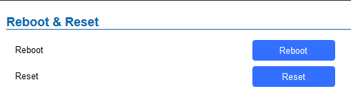
Reboot | When clicked, the GSC3620 will restart (soft reboot). |
Reset | Restore Factory Default Settings |
Debug Log
This page allows user to configure SYSLOG to collect information to help troubleshooting issues with GSC3620.
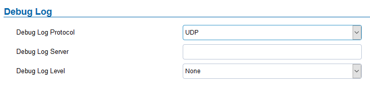
- Users can choose to set Debug Log Protocol to UDP or SSL/TLS.
- Five levels of Debugging are available, None, Debug, Info, Warning, Error.
- Once the Syslog Server and the level entered, press “Save” and then Reboot the device to apply the settings.
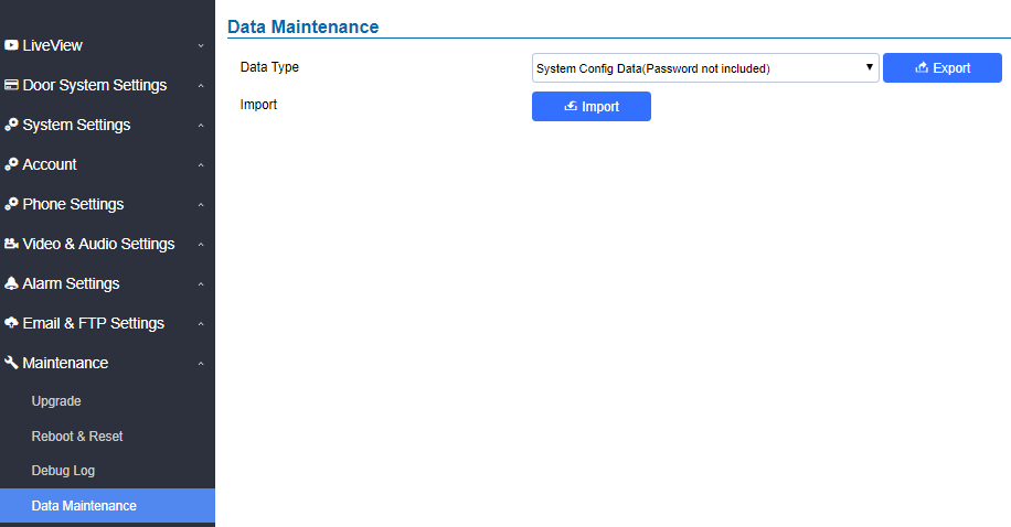
Data Maintenance
This page allows users to manage the GSC3620 configuration file by importing/exporting configuration files.
Event Notification
This page allows users to configure the event notification details that will be used by GSC3620 to communicate to an HTTP server to log the events. When the feature is enabled and configured, all the event logs will be uploaded to server:
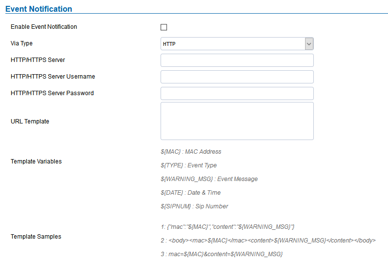
Table 24 : Log Manager Settings
Enable Event Notification | Enables Event Notification feature |
Via Type | Choose which protocol will be used to connect to the logs server (HTTP or HTTPs). |
HTTP/HTTPS Server | Enter the IP address of domain name for the logs server. |
HTTP Server Username | Configure the username of your HTTP(s) server |
HTTP Server Password | Configure the password of your HTTP(s) server |
Specify the template for the event log messages that will be sent to the server, users can use the following variables to customize the message:
|
Certificates
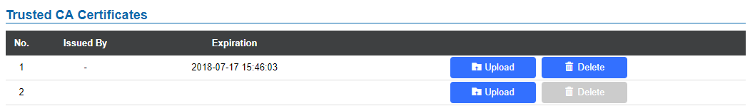
This page allows users to upload up to 6 Trusted CA certificate files which will be trusted by the GSC3620 during SSL exchange. Also, users are allowed to configure the device with custom certificate signed by custom CA certificate under the Custom Certificate section.
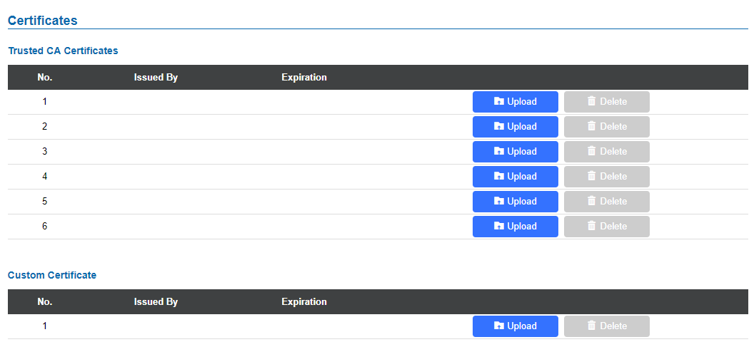
In order to upload your Trusted CA certificate, you may proceed as follows:
-
Click on
 button to upload a file and some related information to the uploaded file will be displayed, such as “Issued by” and “Expiration date”.
-
Users could press
 to delete one of the files.
In order to upload your Custom certificate, you may proceed as follows:
-
Click on
button to upload a file and some related information to the uploaded file will be displayed, such as “Issued by” and “Expiration date”.

Status
This page displays GSC3620 system and network information.
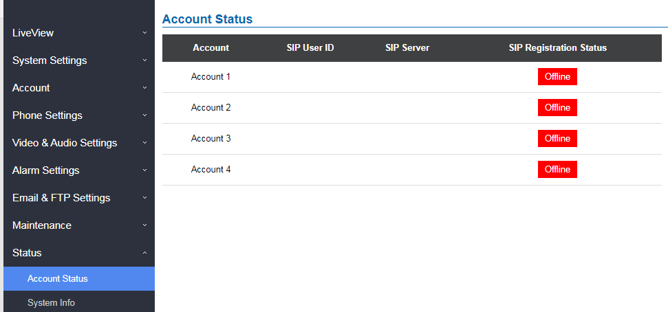
Account Status
This page displays of configured accounts’ SIP user ID, SIP server as well as the SIP Registration status, from Account 1 to Account 4.
System Info
This page displays information such as the product model, the hardware version, firmware…
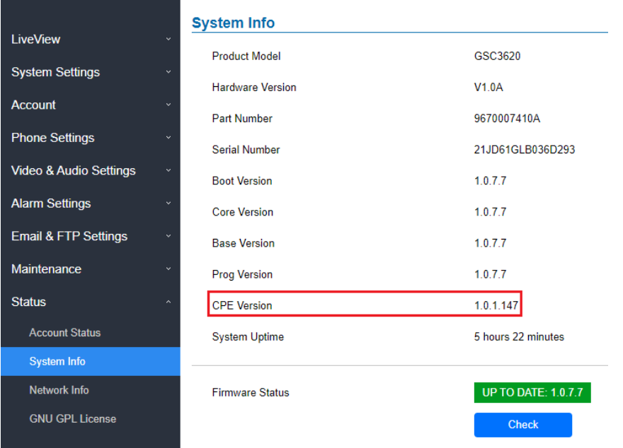
Product Model | Displays the Product Model. |
Hardware Version | Displays the Hardware Version. |
Part Number | Displays the Part Number. |
Displays the Boot Version. | |
Core Version | Displays the Core Version. |
Base Version | Displays the Base Version. |
Prog Version | Displays the Prog Version. |
| CPE Version | Displays the CPE Version. |
System Up Time | Displays the time since the first boot of the GSC3620. |
Click the
|
Network Info
This page displays the network system information of GSC3620.
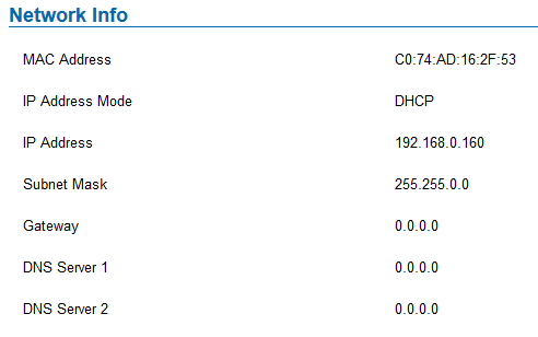
MAC Address | Displays the GSC MAC Address. |
IP Address Mode | Displays the IP address mode used. |
IP Address | Displays the IP address of the GSC3620. |
Subnet Mask | Displays the Subnet Mask used. |
Gateway | Displays the GSC3620 Gateway. |
DNS Server 1 | Displays the Preferred DNS Server. |
DNS Server 2 | Displays the secondary DNS Server. |
FACTORY RESET
Restore to Factory Default via Web GUI
To perform factory reset to the GSC361x via the Web GUI, please refer to following steps:
- Access to GSC361x Web GUI using the using the shipped default password.
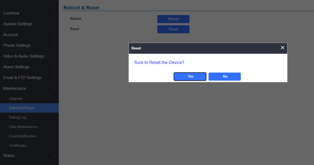
- Navigate to Maintenance 🡪Reboot & Reset.
- Select the reset type from Rest drop down menu and press reset button as displayed on the following screenshot.
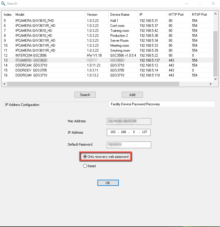
Hard Factory Reset Using GS Search
The GSC3620 can be reset using the GS Search tool by following these steps :
- Open the GS Search tool that can be downloaded from the Grandstream tools page.
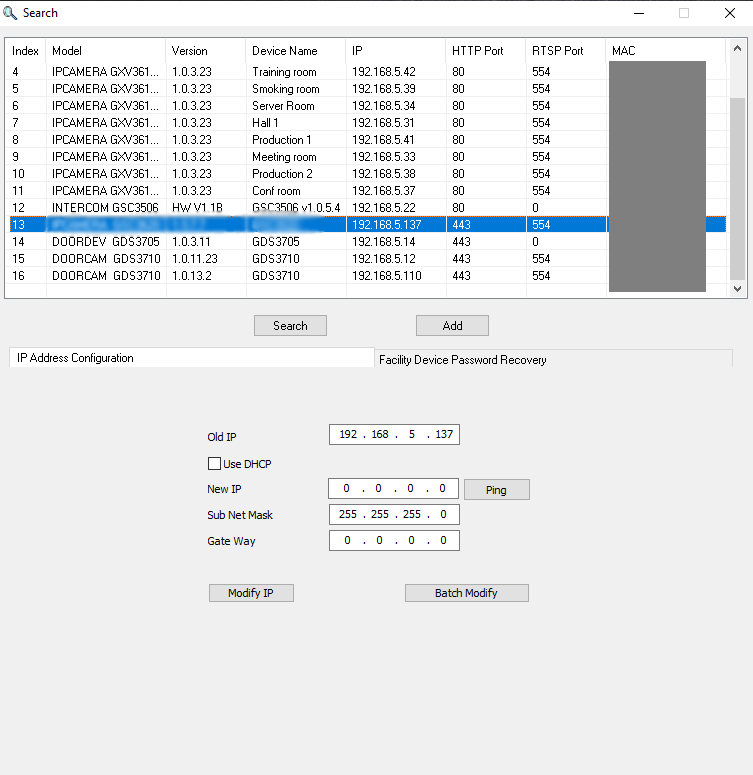
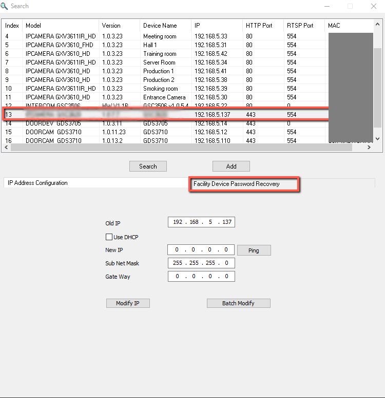
2. Select the device in question, in our example it is the GSC3620, and then select Facility Device Password Recovery.
3. Enter the Default password of the unit which can be found in the stick on the device body or in the package box.
4. Perform the reset of the device by clicking the Reset button option.
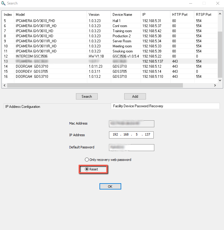
5. You have the possibility to recover the initial default web password as well by selecting the option “only recover web password”
Restore to Factory Default Via SIP NOTIFY
- Access your GSC3620 UI by entering its IP address in your favorite browser.
- Go to Phone Settings.
- Enable “Allow Reset Via SIP NOTIFY” by checking this option. (Default is disabled)
- Once a SIP NOTIFY with “event: reset” is received, the GSC3620 will perform factory reset after authentication phase.
CHANGELOG
This section documents significant changes from previous versions of the user manual for GSC3620 Series. Only major new features or major document updates are listed here. Minor updates for corrections or editing are not documented here.
- Added CPE version displayed in System Info under Status page. [System Info]
- Added support for GSC3620 new hardware versions: 1.0A, 1.0B.
- Added support for GDMS/TR069. [TR069]
- This is the initial version.