
Overview
The GWN7830 is a Layer 3 aggregation managed switch that allows medium-to-large enterprises to build scalable, secure, high-performance, and smart business networks that are fully manageable. It provides 2 10/100/1000Mbps Ethernet ports, 6 SFP ports, and 4 SFP+ ports with a maximum switching capacity of 96Gbps. It supports advanced VLAN for flexible and sophisticated traffic segmentation, advanced QoS for prioritization of network traffic, IGMP/MLD Snooping for network performance optimization, and comprehensive security capabilities against potential attacks. GWN7830 can be managed in several ways, including the local Web user interface of the GWN7830 switch and CLI, the command-line interface and also supported by GWN. Cloud and GWN Manager, Grandstream’s cloud and on-premise network management platform. With complete end-to-end quality of service and flexible security settings, the GWN7830 is the best value enterprise-grade managed switch for medium-to-large businesses.
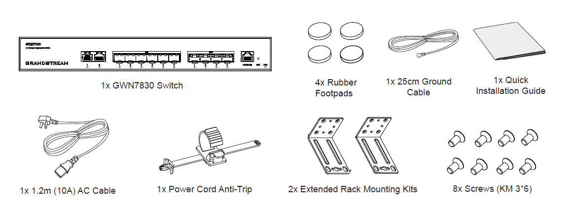
Package Content
PORTS & LED INDICATORS
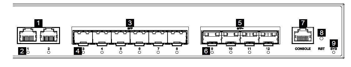
Front Panel
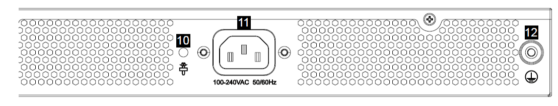
Back Panel
No. | Port & LED | Description |
1 | Ports 1-2 | 2x 10/100/1000Mbps Ethernet ports |
2 | 1-2 | Ethernet ports’ LED indicators |
3 | Ports 3-8 | 6x 1Gbps SFP ports |
4 | 3-8 | SFP ports’ LED indicators |
5 | Ports 9-12 | 4x 10Gbps SFP+ ports |
6 | 9-12 | SFP+ ports’ LED indicators |
7 | Console | 1x Console port, used to connect a PC directly to the switch and manage it. |
8 | RST | Factory Reset pinhole, press for 5 seconds to reset factory default settings |
9 | SYS | System LED indicator |
10 |  | Power cord anti-trip hole |
11 | 100-240VAC | Power socket |
12 |  | Grounding terminal |
Port Indicators
LED Indicator
LED Indicator | Status | Description |
System Indicator | Off | Power off |
Solid green | Booting | |
Flashing green | Upgrade | |
Solid blue | Normal use | |
Flashing blue | Provisioning | |
Solid red | Upgrade failed | |
Flashing red | Factory reset | |
Port Indicator | Off | Port off |
Solid green | Port connected and there is no activity | |
Flashing green | Port connected and data is transferring |
LED Indicators
POWERING & CONNECTING
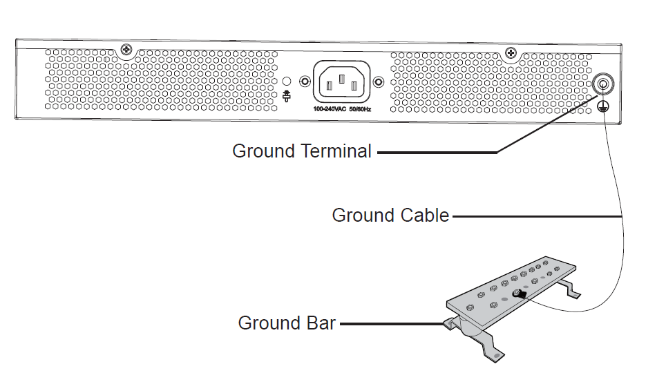
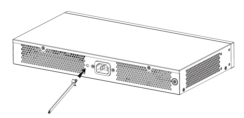
Grounding the Switch
- Remove the ground screw from the back of switch, and connect one end of the ground cable to the wiring terminal of switch.
- Put the ground screw back into the screw hole, and tighten it with a screwdriver.
- Connect the other end of the ground cable to other device that has been grounded or directly to the terminal of the ground bar in the equipment room.
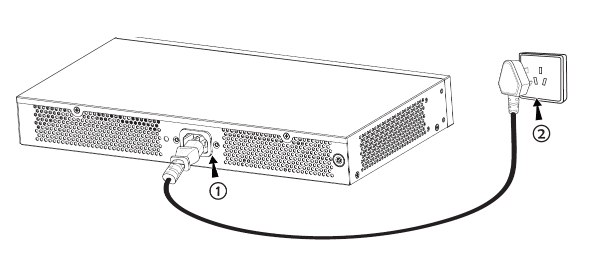
Powering on the Switch
Connect the power cable and the switch first, then connect the power cable to the power supply system of the equipment room.
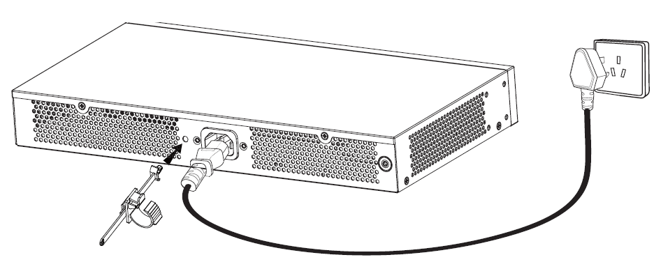
Connecting Power Cord Anti-Trip
In order to protect the power supply from accidental disconnection, it’s recommended to use a power cord anti-trip for installation.
- Force the head of the fixing strap tightly into the hole next to the power socket until it’s buckled on the shell without falling off.
- After plugging the power cord into the power outlet, slide the protector over the remaining strap until it slides over the end of the power cord.
- Wrap the strap of the protective cord around the power cord and lock it tightly. Fasten the straps until the power cord is securely fastened.
PORT CONNECTING
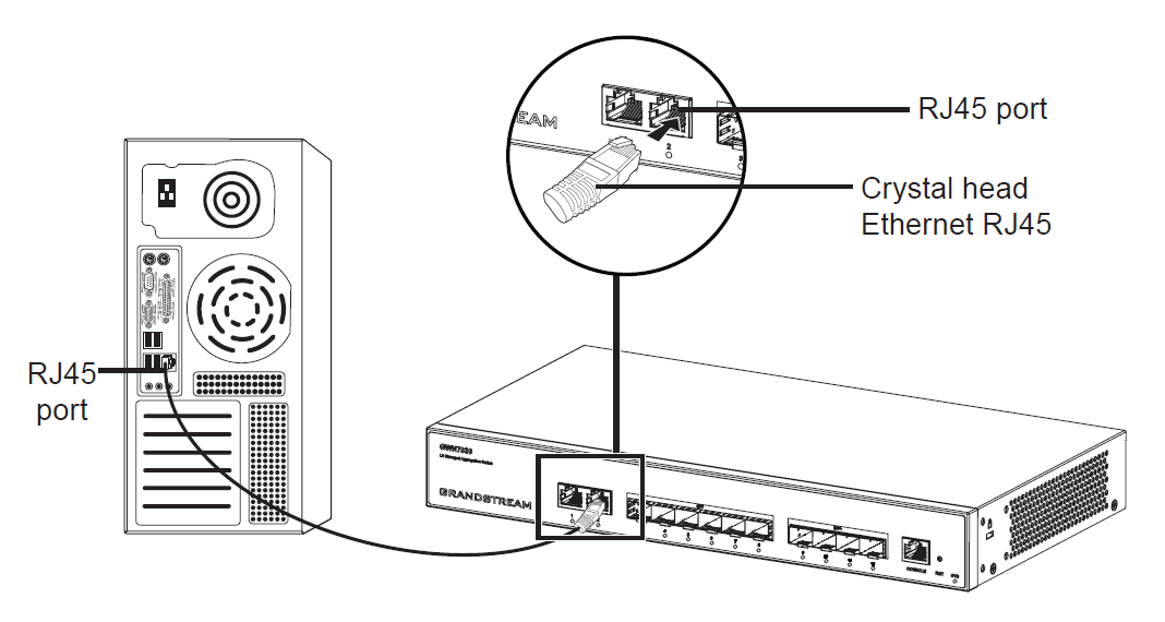
Connect to RJ45 Port
- Connect one end of the network cable to the switch, and the other end to the peer device.
- After powered on, check the status of the port indicator. If on, it means that the link is connected normally; if off, it means the link is disconnected, please check the cable and the peer device whether is enabled.
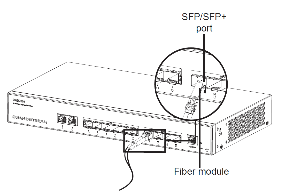
Connect to SFP/SFP+ Port
The installation process of the fiber module is as follows:
- Grasp the fiber module from the side and insert it smoothly along the switch SFP/SFP+ port slot until the module is in close contact with the switch.
- When connecting, pay attention to confirm the Rx and Tx ports of SFP/SFP+ fiber module. Insert one end of the fiber into the Rx and Tx ports correspondingly, and connect the other end to another device.
- After powered on, check the status of the port indicator. If on, it means that the link is connected normally; if off, it means the link is disconnected, please check the cable and the peer device whether is enabled.
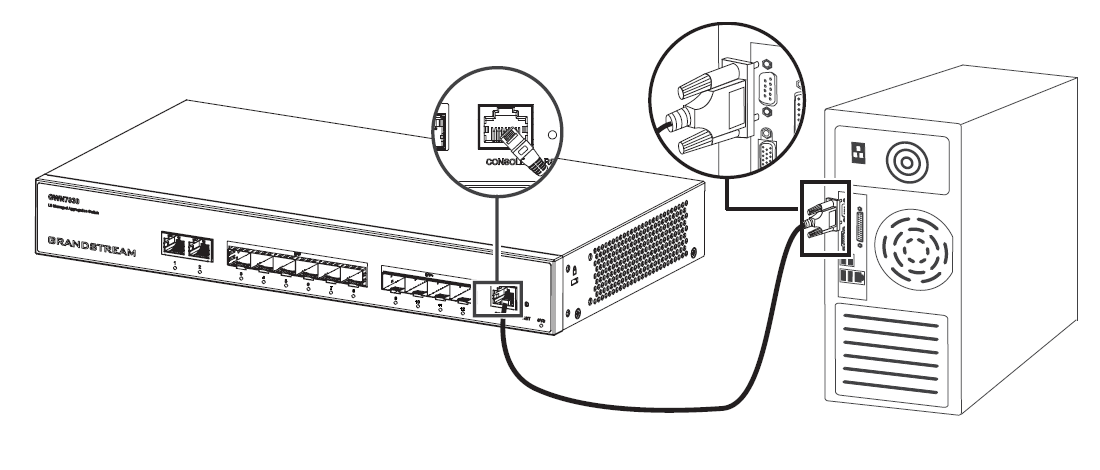
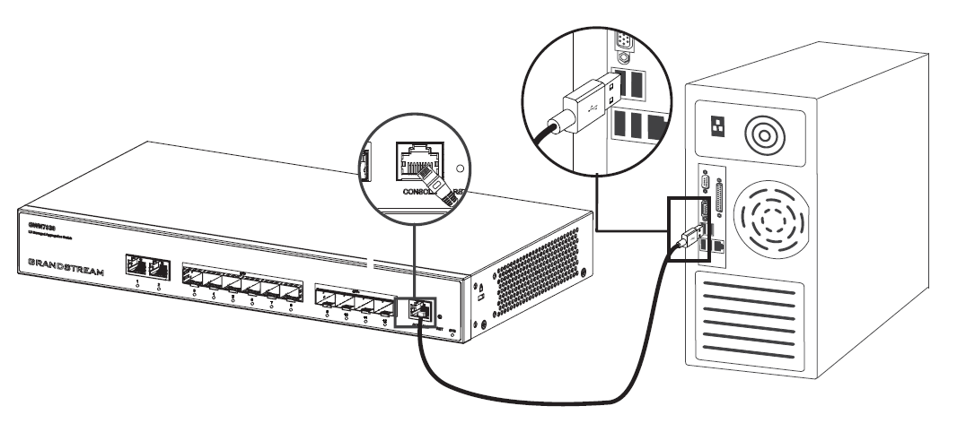
Connect to Console Port
- Connect the console cable (prepared by yourself) to the DB9 male connector or USB port to the PC.
- Connect the other end of the RJ45 end of the console cable to the console port of switch.
INSTALLATION
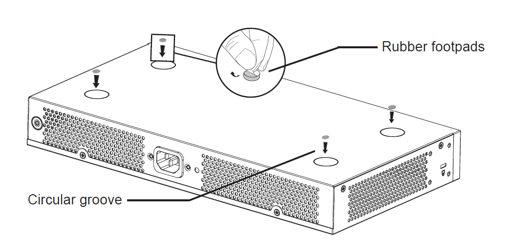
Install on the Desktop
- Place the bottom of switch on a sufficiently large and stable table.
- Peel off the rubber protective paper of the four foot pads one by one, and stick them in the corresponding circular grooves at the four corners of the bottom of the case.
- Flip the switch over and place it smoothly on the table.
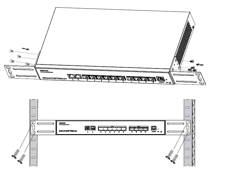
Install on a 19” Standard Rack
- Check the grounding and stability of the rack.
- Install the two extended rack-mounting in the accessories on both sides of switch, and fix them with the screws provided (KM 3*6).
- Place the switch in a proper position in the rack and support it by the bracket.
- Fix the extended rack-mounting to the guide grooves at both ends of the rack with screws (prepared by yourself) to ensure that the switch is stable and horizontally installed on the rack.
ACCESS & CONFIGURE
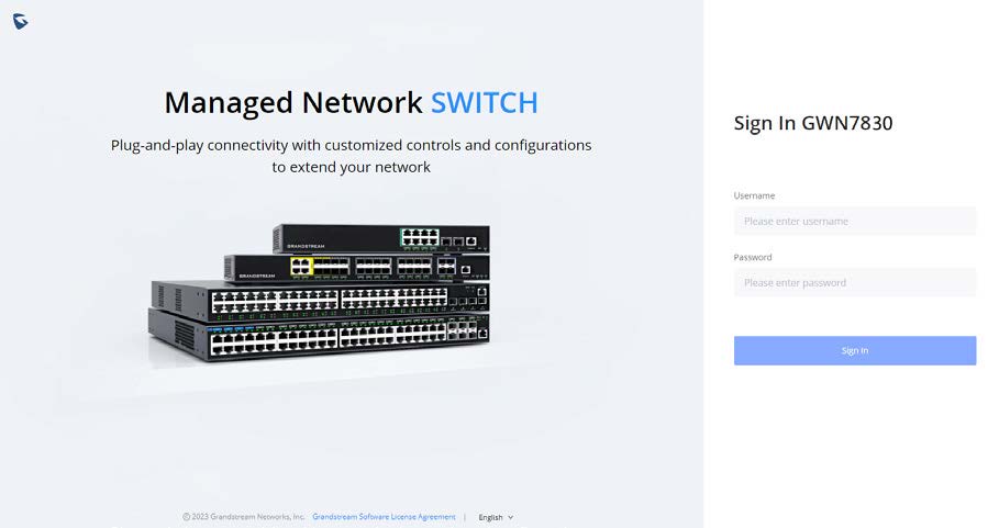
Method 1: Login using the Web UI
- A PC uses a network cable to correctly connect any RJ45 port of the switch.
- Set the Ethernet (or local connection) IP address of the PC to 192.168.0.x (“x” is any value between 1-253), and the subnet mask to 255.255.255.0, so that it is in the same network segment with switch IP address. If DHCP is used, this step could be skipped.
- Type the switch’s management IP address http://<GWN7830_IP> in the browser, and enter username and password to login. (The default administrator username is “admin” and the default random password can be found at the sticker on the GWN7830 switch).
Method 2: Login using the Console port
- Use the console cable to connect the console port of switch and the serial port of PC.
- Open the terminal emulation program of PC (e.g. SecureCRT), enter the default username and password to login. (The default administrator username is “admin” and the default random password can be found at the sticker on the GWN7830 switch).
Method 3: Login Remotely using SSH/Telnet
- Turn on the Telnet of the switch.
- Enter “cmd” in PC/Start.
- Enter telnet <GWN7830_IP> in the cmd window.
- Enter the default username and password to login. (The default administrator username is “admin” and the default random password can be found at the sticker on the GWN7830 switch).
Method 4: Configure using GWN.Cloud/GWN Manager
Type https://www.gwn.cloud (https:// for GWN Manager) in the browser, and enter the account and password to login the cloud platform. If you don’t have an account, please register first or ask the administrator to assign one for you.
Refer to online documents and FAQ for more detailed information:
https://www.grandstream.com/our-products