
Thank you for purchasing Grandstream GXV34x0 IP Multimedia Phone for AndroidTM. The GXV34x0 IP Video Phone for Android combines a 16-line IP video phone with a multi-platform video conferencing solution and the functionality of an Android tablet to offer an all-in-one communications solution. All the models come with HD resolution capacitive touch screen with different sizes, GXV3450 has 5″ 1280×720 while GXV3470 and GXV3480 come 1280×800 and they support 7″ and 8″ respectively, tiltable camera with privacy shutter that supports 1080p 30fps HD video, dual Gigabit ports with PoE/PoE+, HD audio, integrated Wi-Fi (Dual band 802.11a/b/g/n/ac) for GXV3450 and Wi-Fi 6 (Dual band 802.11a/b/g/n/ac/ax) for GXV3470 and GXV3480 & Bluetooth 5, rich peripheral interfaces, and Android 11 By combining a state-of-the-art IP video phone, an advanced video conferencing solution, and the functionality of a tablet, businesses throughout the world can now use the GXV34x0 for all communication and productivity needs.
PRODUCT OVERVIEW
Feature Highlights
The following tables contain the major features of the GXV34x0:
 GXV3480 |
|
 GXV3470 |
|
 GXV3450 |
|
GXV34x0 Features in a Glance
Technical Specifications
The following tables resume all the technical specifications including the protocols / standards supported, voice codecs, telephony features, languages and upgrade/provisioning settings for the GXV34x0 series.
- GXV3480 Technical Specifications
Protocols/Standards | SIP RFC3261, TCP/IP/UDP, RTP/RTCP, HTTP/HTTPS, ARP, ICMP, DNS (A record, SRV, NAPTR), DHCP, PPPoE, SSH, TFTP, NTP, STUN, SIMPLE, LLDP-MED, LDAP, TR-069, 802.1x, TLS, SRTP, IPv6, OpenVPN® |
Network Interfaces | Dual switched 10/100/1000 Mbps ports with integrated PoE/PoE+ |
Graphic Display | 8" 1280×800 capacitive touch screen (10 points) IPS LCD |
Camera | Tiltable 2 megapixel CMOS camera with privacy shutter, 1080p 30fps |
Bluetooth | Yes, integrated Bluetooth |
Wi-Fi | Yes, dual-band (2.4GHz & 5GHz) with 802.11 a/b/g/n/ac/ax, 2T2R, Wi-Fi Display & AirPlay |
Auxiliary Ports | RJ9 headset jack (allowing EHS with Plantronics headsets), 3.5mm stereo headset with microphone, USB 3.0 port, Type-C, HDMI-out, HDMI-in |
Feature Keys | 2 function touch keys VOLUME +/-, 3 dedicated Android touch keys HOME, MENU, and BACK |
Voice Codec | Wide-band Opus, wide-band G.722, G.711μ/a, G.729A/B, G.726-32, iLBC, in-band and out-ofband DTMF (In audio, RFC2833, SIP INFO), VAD, CNG, AEC, PLC, AJB, AGC, ANS, Noise Shield 2.0 |
Video Codec and Capabilities | H.264 BP/MP/HP, video resolution up to 1080p, frame rate up to 30 fps, bit rate up to 4Mbps, 3-way video conference (1080p@30fps), BFCP, people video(up to 1080p@30fps) + content video(up to 1080p@15fps), anti-flickering and auto exposure |
Telephony Features | Hold, transfer, forward (unconditional/no-answer/busy), call park/pickup, 12-way audio conference(including the host), shared-call-appearance (SCA) / bridged-line-appearance (BLA), virtual MPK, downloadable contacts (XML, LDAP, up to 2000 items), call record(local and server), call log (up to 2000 records), call waiting, auto answer, XML customization of screen, flexible dial plan, personalized music ringtones and music on hold, server redundancy & fail-over |
Sample Applications |
|
Android | Runs Android 11 |
Applications Deployment | Supports Android 11 compliant applications to be developed, downloaded and run on the device with provisioning control. |
HD Audio | Yes, 2 omnidirectional microphones, HD handset and speakerphone with support for wideband audio |
Base Stand | Integrated stand with multiple adjustable angles |
QoS | Layer 2 QoS (802.1Q, 802.1p) and Layer 3 (ToS, DiffServ, MPLS) QoS |
Security | User and administrator level passwords, random default admin password, MD5 and MD5-sess based authentication, 256-bit AES encrypted configuration file, TLS, SRTP, HTTPS, 802.1x media access control, Kensington Security Slot (Kensington Lock) support, anti-hacking secure boot |
Multi-language | English, German, Italian, French, Spanish, Portuguese, Russian, Croatian, Chinese, Korean, Japanese, and more |
Upgrade/Provisioning | Firmware upgrade via TFTP / HTTP / HTTPS or local HTTP upload, mass provisioning using TR-069 or AES encrypted XML configuration file, GDMS. |
Power & Green Energy Efficiency | Universal power adapter included: Input: 100-240VAC 50-60Hz; Output 12VDC 1.5A (18W) |
Temperature and Humidity | Operation: 0°C to 40°C Storage: -10°C to 60°C Humidity: 10% to 90% Non-condensing |
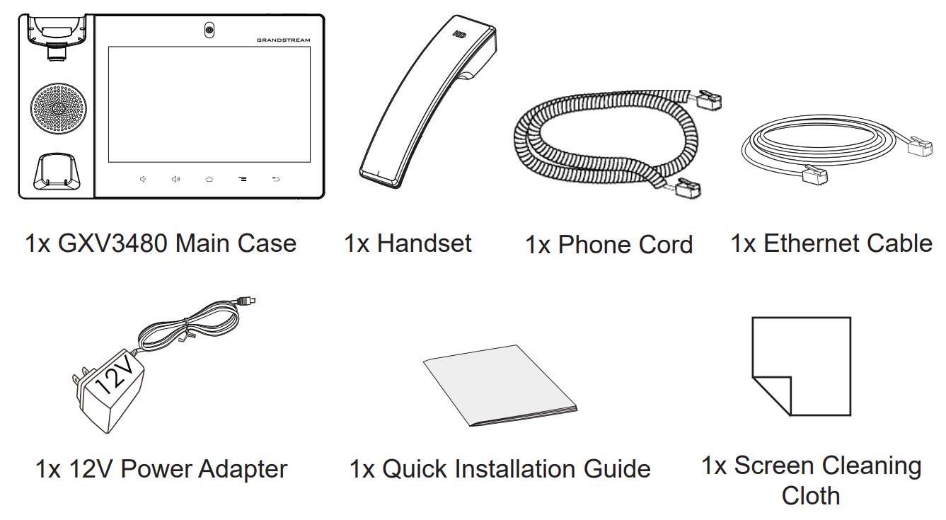
Package Content | GXV3480 phone, handset with cord, base stand, universal power supply, network cable, screen cleaning cloth, quick installation guide |
Compliance | FCC: CFR 47 Part 15 Subpart B Class B; CFR 47 Part 15 Subpart C; CFR 47 Part 15 Subpart E; Part 68 (HAC) IC: RSS-247, RSS-GEN, RSS-102, ICES-003, CS-03. CE: EN 55032 Class B;EN 55035; EN IEC 61000-3-2; EN 61000-3-3; EN IEC 62368-1; ETSI EN 300328; ETSI EN 301893; ETSI EN 301489-1; ETSI EN 301489-17; EN IEC 62311 UKCA: BS EN 55032 Class B; BS EN 55035; BS EN IEC 61000-3-2; BS EN 61000-3-3; BS EN IEC 62368-1; ETSI EN 300328; ETSI EN 301893; ETSI EN 301489-1; ETSI EN 301489-17; BS EN IEC 62311 RCM: AS/ACIF S040 AS/CA S004; AS/NZS CISPR 32; AS/NZS 62368.1; AS/NZS 4268. HDMI RoHS 2.0 |
GXV3480 Technical Specifications
- GXV3470 Technical Specifications
Protocols/Standards | SIP RFC3261, TCP/IP/UDP, RTP/RTCP, HTTP/HTTPS, ARP, ICMP, DNS (A record, SRV, NAPTR), DHCP, PPPoE, SSH, TFTP, NTP, STUN, SIMPLE, LLDP-MED, LDAP, TR-069, 802.1x, TLS, SRTP, IPv6, OpenVPN® |
Network Interfaces | Dual switched 10/100/1000 Mbps ports with integrated PoE/PoE+ |
Graphic Display | 7" 1280×800 capacitive touch screen (5 points) HD IPS LCD |
Camera | Tiltable 2 megapixel CMOS camera with privacy shutter, 1080p 30fps |
Bluetooth | Yes, integrated Bluetooth |
Wi-Fi | Yes, dual-band (2.4GHz & 5GHz) with 802.11 a/b/g/n/ac/ax, 2T2R, Wi-Fi Display & AirPlay |
Auxiliary Ports | RJ9 headset jack (allowing EHS with Plantronics headsets), 3.5mm headset port, USB 2.0 port, USB 3.0 port, HDMI-out |
Feature Keys | 2 function touch keys VOLUME +/-, 3 dedicated Android touch keys HOME, MENU, and BACK |
Voice Codec | Wide-band Opus, wide-band G.722, G.711μ/a, G.729A/B, G.726-32, iLBC, in-band and out-ofband DTMF (In audio, RFC2833, SIP INFO), VAD, CNG, AEC, PLC, AJB, AGC, ANS, Noise Shield 2.0 |
Video Codec and Capabilities | H.264 BP/MP/HP, video resolution up to 720p, frame rate up to 30 fps, bit rate up to 2Mbps, 3-way video conference (720p@30fps), anti-flickering and auto exposure |
Telephony Features | Hold, transfer, forward (unconditional/no-answer/busy), call park/pickup, 10-way audio conference(including the host), shared-call-appearance (SCA) / bridged-line-appearance (BLA), virtual Programmable Key, downloadable contacts (XML, LDAP, up to 1000 items), call record(local and server), call log (up to 1000 records), call waiting, auto answer, XML customization of screen, flexible dial plan, personalized music ringtones and music on hold, server redundancy & fail-over |
Sample Applications |
|
Android | Runs Android 11 |
Applications Deployment | Supports Android 11 compliant applications to be developed, downloaded and run on the device with provisioning control. |
HD Audio | Yes, 2 omnidirectional microphones, HD handset and speakerphone with support for wideband audio |
Base Stand | Yes, built-in stand with multiple adjustable angles |
QoS | Layer 2 QoS (802.1Q, 802.1p) and Layer 3 (ToS, DiffServ, MPLS) QoS |
Security | User and administrator level passwords, random default admin password, MD5 and MD5-sess based authentication, 256-bit AES encrypted configuration file, TLS, SRTP, HTTPS, 802.1x media access control, Kensington Security Slot (Kensington Lock) support, anti-hacking secure boot |
Multi-language | English, German, Italian, French, Spanish, Portuguese, Russian, Croatian, Chinese, Korean, Japanese, and more |
Upgrade/Provisioning | Firmware upgrade via TFTP / HTTP / HTTPS or local HTTP upload, mass provisioning using TR-069 or AES encrypted XML configuration file, GDMS. |
Power & Green Energy Efficiency | Universal power adapter included: Input: 100-240VAC 50-60Hz; Output 12VDC 1.5A (18W) |
Temperature and Humidity | Operation: 0°C to 40°C Storage: -10°C to 60°C Humidity: 10% to 90% Non-condensing |
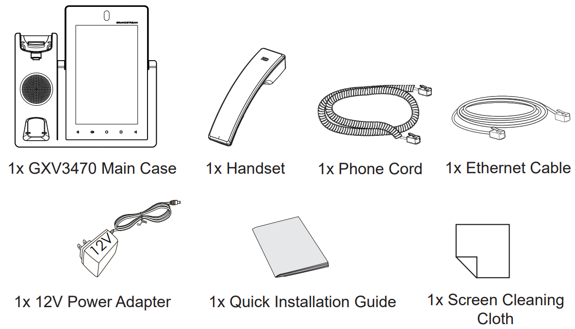
Package Content | GXV3470 phone, handset with cord, base stand, universal power supply, network cable, screen cleaning cloth, quick installation guide |
Compliance | FCC: CFR 47 Part 15 Subpart B Class B; CFR 47 Part 15 Subpart C; CFR 47 Part 15 Subpart E; Part 68 (HAC) IC: RSS-247, RSS-GEN, RSS-102, ICES-003, CS-03 CE: EN 55032 Class B;EN 55035; EN IEC 61000-3-2; EN 61000-3-3; EN IEC 62368-1; ETSI EN 300328; ETSI EN 301893; ETSI EN 301489-1; ETSI EN 301489-17; EN IEC 62311 UKCA: BS EN 55032 Class B; BS EN 55035; BS EN IEC 61000-3-2; BS EN 61000-3-3; BS EN IEC 62368-1; ETSI EN 300328; ETSI EN 301893; ETSI EN 301489-1; ETSI EN 301489-17; BS EN IEC 62311 RCM: AS/ACIF S040 AS/CA S004; AS/NZS CISPR 32; AS/NZS 62368.1; AS/NZS 4268 HDMI , RoHS 2.0 |
GXV3470 Technical Specifications
- GXV3450 Technical Specifications
Protocols/Standards | SIP RFC3261, TCP/IP/UDP, RTP/RTCP, HTTP/HTTPS, ARP, ICMP, DNS (A record, SRV, NAPTR), DHCP, PPPoE, SSH, TFTP, NTP, STUN, LLDP-MED, LDAP, TR-069, 802.1x, TLS, SRTP, IPv6, OpenVPN® |
Network Interfaces | Dual switched 10/100/1000 Mbps ports with integrated PoE/PoE+ |
Graphic Display | 5.0 inch 1280×720 capacitive touch screen (5 points) HD IPS LCD |
Camera | Tiltable 2 megapixel CMOS camera with privacy shutter, 1080p 30fps |
Bluetooth | Yes, integrated Bluetooth |
Wi-Fi | Yes, dual-band dual-stream Wi-Fi 5(2.4GHz & 5GHz) with 802.11 a/b/g/n/ac |
Auxiliary Ports | RJ9 headset jack (allowing EHS with Plantronics headsets), USB 2.0 port, USB 3.0 port |
Feature Keys | 11 functions keys for CONFERENCE, TRANSFER, SEND/REDIAL, MUTE, EARPHONE, SPEAKERPHONE, VOLUME -/+. 3 dedicated Android keys for HOME, RECENT, and BACK |
Voice Codec | Wide-band Opus, wide-band G.722, G.711μ/a, G. 729A/B, G.726-32, iLBC, in-band and out-ofband DTMF (In audio, RFC2833, SIP INFO), VAD, CNG, AEC, PLC, AJB, AGC, ANS, Noise Shield 2.0 |
Video Codec and Capabilities | H.264 BP/MP/HP, video resolution up to 720p, frame rate up to 30 fps, bit rate up to 2Mbps, 3-way video conference (720p@30fps), anti-flickering and auto exposure |
Telephony Features | Hold, transfer, forward (unconditional/no-answer/busy), call park/pickup, 10-way audio conference(including the host), shared-call-appearance (SCA) / bridged-line-appearance (BLA), virtual |
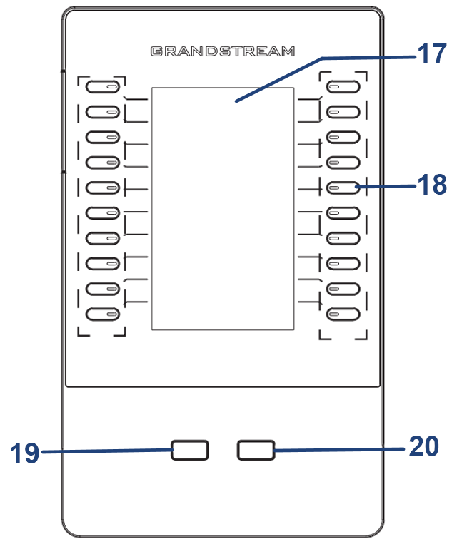
Extention Module | Yes, can power up to 4 GBX20 EXT modules which feature a 272x480 color LCD, 20 quick-dial/BLF keys with dual-color LED, 2 navigation keys, and less than 1.2W power consumption per unit. |
Sample Applications |
|
Android | Runs Android 11 |
Applications Deployment | Supports Android 11 compliant applications to be developed, downloaded and run on the device with provisioning control. |
HD Audio | Yes, 2 omnidirectional microphones, HD handset and speakerphone with support for wideband audio |
Base Stand | Yes, desktop stand with three adjustable levels |
QoS | Layer 2 QoS (802.1Q, 802.1p) and Layer 3 (ToS, DiffServ, MPLS) QoS |
Security | User and administrator level passwords, random default admin password, MD5 and MD5-sess based authentication, 256-bit AES encrypted configuration file, TLS, SRTP, HTTPS, 802.1x media access control, Kensington Security Slot (Kensington Lock) support, anti-hacking secure boot |
Multi-language | English, German, Italian, French, Spanish, Portuguese, Russian, Croatian, Chinese, Korean, Japanese, and more |
Upgrade/Provisioning | Firmware upgrade via TFTP / HTTP / HTTPS or local HTTP upload, mass provisioning using TR-069 or AES encrypted XML configuration file, GDMS |
Power & Green Energy Efficiency | Universal power adapter included: Input: 100-240VAC 50-60Hz; Output 12VDC 1.5A (18W) |
Temperature and Humidity | Operation: 0°C to 40°C Storage: -10°C to 60°C Humidity: 10% to 90% Non-condensing |
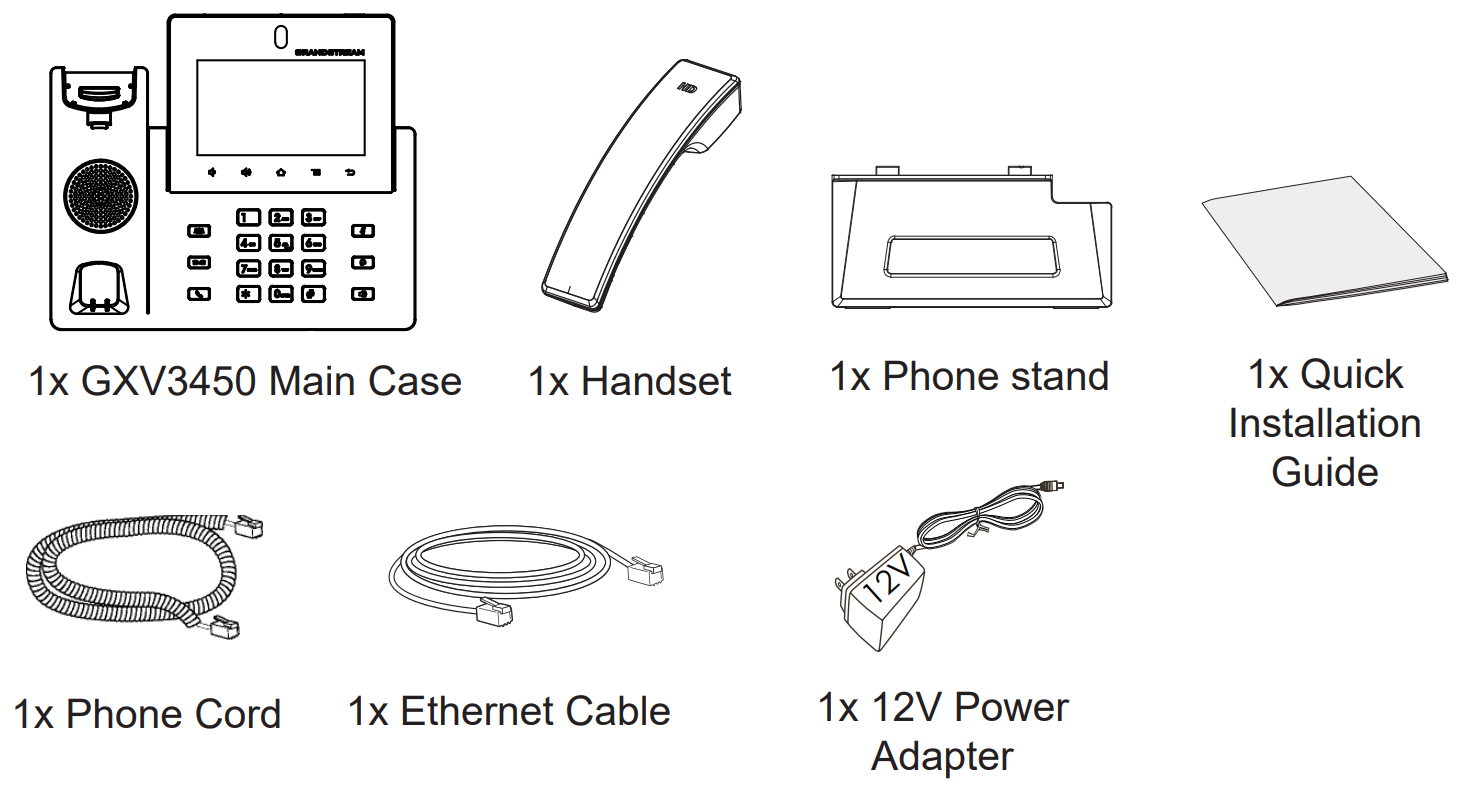
Package Content | GXV3450 phone, handset with cord, base stand, universal power supply, network cable, screen cleaning cloth, quick installation guide |
Compliance | FCC: CFR 47 Part 15 Subpart B Class B; CFR 47 Part 15 Subpart C; CFR 47 Part 15 Subpart E; Part 68 (HAC) IC: RSS-247, RSS-GEN, RSS-102, ICES-003, CS-03 CE: EN 55032 Class B;EN 55035; EN IEC 61000-3-2; EN 61000-3-3; EN IEC 62368-1; ETSI EN 300328; ETSI EN 301893; ETSI EN 301489-1; ETSI EN 301489-17; EN IEC 62311 UKCA: BS EN 55032 Class B; BS EN 55035; BS EN IEC 61000-3-2; BS EN 61000-3-3; BS EN IEC 62368-1; ETSI EN 300328; ETSI EN 301893; ETSI EN 301489-1; ETSI EN 301489-17; BS EN IEC 62311 RCM: AS/ACIF S040 AS/CA S004; AS/NZS CISPR 32; AS/NZS 62368.1; AS/NZS 4268 RoHS2.0 |
GXV3450 Technical Specifications
GETTING STARTED
Equipment Packaging
This chapter provides basic installation instructions including the list of the packaging contents and also information for obtaining the best performance with the GXV34x0 series.
- GXV3480
GXV3480 |
|
GXV3480 Equipment Packaging
- GXV3470
GXV3470 |
|
GXV3470 Equipment Packaging
- GXV3450
GXV3450 |
|
GXV3450 Equipment Packaging
Description of the GXV34x0
GXV3480
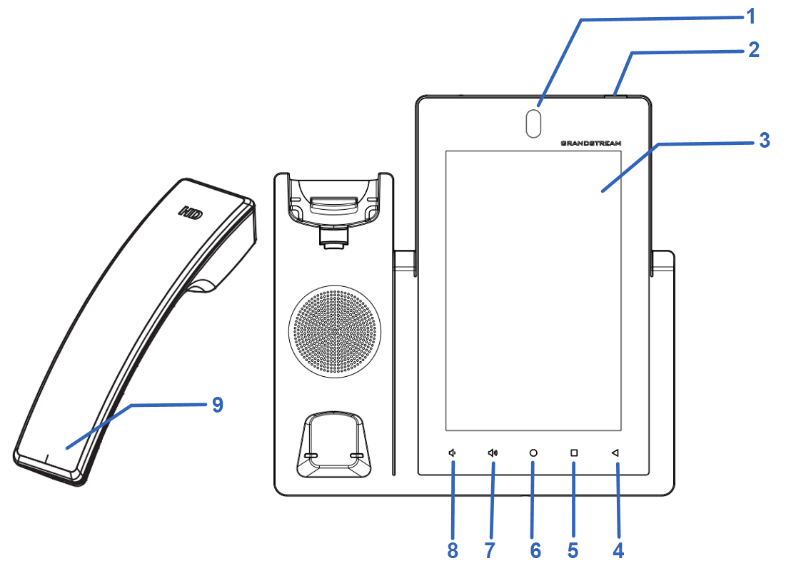
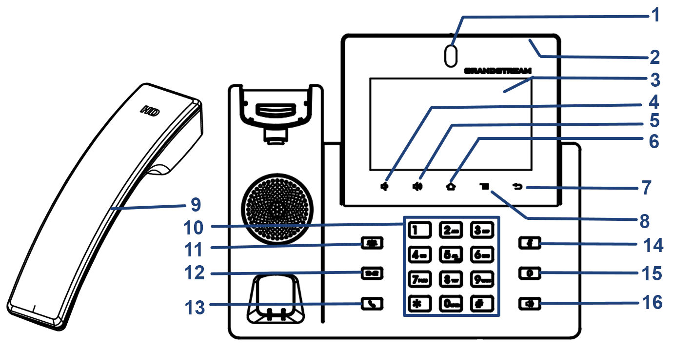
- Front View
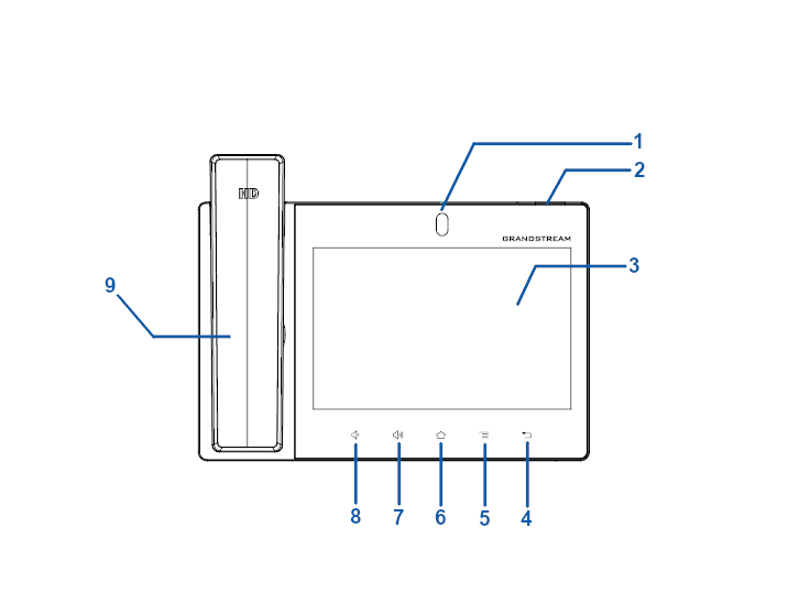
| Item | Name | Description |
| 1 | Front Camera | Mega pixel front camera. The angle can be adjusted, and the camera can be blocked by scrolling up/down the wheel on the back of the camera. |
| 2 | MWI LED Indicator | To indicate message status, call status and phone’s system status using the LED indicator. |
| 3 | LCD | 8″ (1280×800) capacitive (10 points) IPS LCD touch screen. |
| 4 | Back | Tap to go back to the previous menu. |
| 5 | Menu | Press MENU key to access phone’s display settings, edit widgets and thread manager. Or press and hold on the MENU key for 2 seconds to enter managing application interface directly. |
| 6 | Home | Tap to go back to Home screen; or touch and press for about 2 seconds to take a screenshot of phone’s screen. |
| 7 | Volume Up | Tap to turn up the call volume and media volume. |
| 8 | Volume Down | Tap to turn down the call volume and media volume. |
| 9 | Handset | Off hook to use handset as the audio channel for calls and media. |
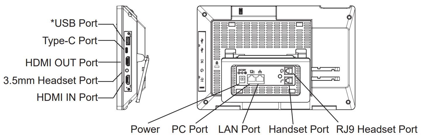
- Back View
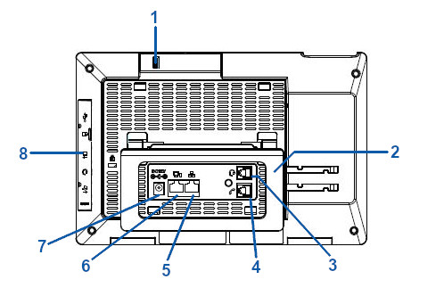
| Item | Name | Description |
| 1 | Camera Adjusting Wheel | Scroll up/down to adjust the camera angle. |
| 2 | Phone Stand (built-in) | Adjust the phone stand angle to place the phone on the desk. |
| 3 | Headset Port | RJ9 headset connector port (supporting EHS with Plantronics headset). |
| 4 | Handset Port | RJ9 handset connector port. |
| 5 | LAN Port | 10/100/1000Mbps RJ-45 port connecting to Ethernet. PoE/PoE+ is supported. |
| 6 | PC Port | 10/100/1000Mbps RJ-45 port connecting to PC. |
| 7 | Power Jack | 12V DC Power connector port. |
| 8 | Side Connectors Cover | USB 3.0 port, Type-C, HDMI-out, 3.5mm headset port, HDMI-in” Note: Type-C port only supports data transfer and charging , and not video output. |
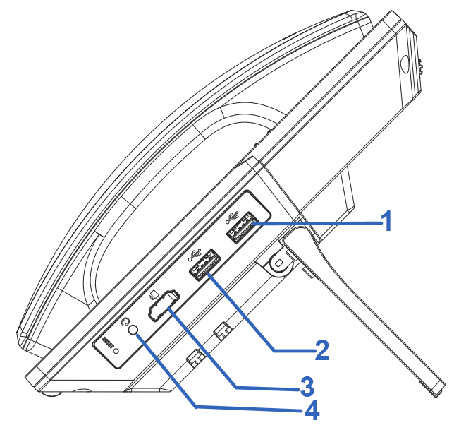
- Side View
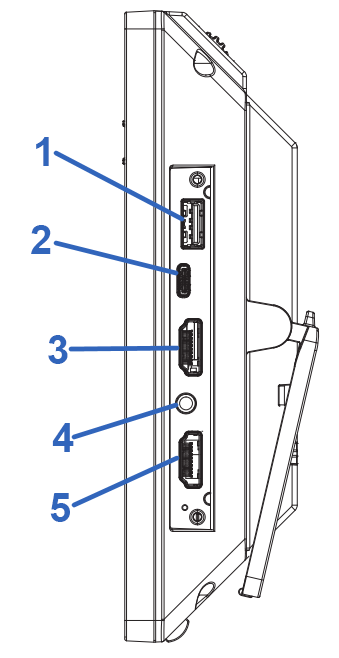
| Item | Name | Description |
| 1 | USB Port | USB devices can be connected via the USB port. For example, connect a USB flash drive to save captured pictures. |
| 2 | Type-C port | Used for USB Device mode. Connect the GXV3480 to a USB Host device, such as a PC, the GXV3480 will act as its USB external audio device. |
| 3 | HDMI Output Interface | Connect to HDMI input devices (e.g., TV) |
| 4 | 3.5mm Headset Port | Connect 3.5mm headset. |
| 5 | HDMI Input Interface | Connect presentation device (e.g., a laptop). |
GXV3470
- Font View
| Item | Name | Description |
| 1 | Front Camera | Mega pixel front camera. The angle can be adjusted, and the camera can be blocked by scrolling up/down the wheel on the back of the camera. |
| 2 | MWI LED Indicator | To indicate message status, call status and phone’s system status using the LED indicator. |
| 3 | LCD | 7″ (1280×800) capacitive (5 points) IPS LCD touch screen. |
| 4 | Back | Tap to go back to the previous menu. |
| 5 | Menu | Press MENU key to access phone’s display settings, edit widgets and thread manager. Or press and hold on the MENU key for 2 seconds to enter managing application interface directly. |
| 6 | Home | Tap to go back to Home screen; or touch and press for about 2 seconds to take a screenshot of phone’s screen. |
| 7 | Volume Up | Tap to turn up the call volume and media volume. |
| 8 | Volume Down | Tap to turn down the call volume and media volume. |
| 9 | Handset | Off hook to use handset as the audio channel for calls and media. |
- Back View
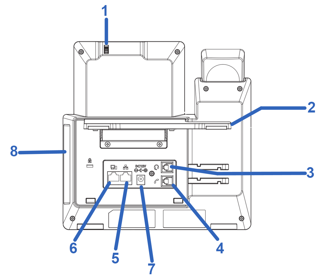
| Item | Name | Description |
| 1 | Camera Adjusting Wheel | Scroll up/down to adjust the camera angle. |
| 2 | Phone Stand (built-in) | Adjust the phone stand angle to place the phone on the desk. |
| 3 | Headset Port | RJ9 headset connector port (supporting EHS with Plantronics headset). |
| 4 | Handset Port | RJ9 handset connector port. |
| 5 | LAN Port | 10/100/1000Mbps RJ-45 port connecting to Ethernet. PoE/PoE+ is supported. |
| 6 | PC Port | 10/100/1000Mbps RJ-45 port connecting to PC. |
| 7 | Power Jack | 12V DC Power connector port. |
| 8 | Side Connectors Cover | USB 3.0 Port, USB 2.0 Port, HDMI Port, 3.5mm Headset Port. |
- Side View
| Item | Name | Description |
| 1 | USB 3.0 Port | Faster USB 3.0 port to storage as an example. |
| 2 | USB 2.0 Port | USB devices can be connected via the USB port. For example, connect a USB flash drive to save captured pictures. |
| 3 | HDMI Output Interface | Connect to HDMI input devices (e.g., TV). |
| 4 | 3.5mm Headset Port | Connect 3.5mm headset. |
GXV3450
- Front View
Item | Name | Description |
1 | Camera Adjusting Wheel | Scroll up/down to adjust the camera angle. |
2 | Phone Stand Slot | Put the phone stand from left to right into the slots. |
3 | Handset Port | RJ9 handset connector port. |
4 | Headset Port | RJ9 headset connector port (supporting EHS with Plantronics headset). |
5 | Power Jack | 12V DC Power connector port. |
6 | LAN Port | 10/100/1000Mbps RJ-45 port connecting to Ethernet. PoE/PoE+ is supported |
7 | PC Port | 10/100/1000Mbps RJ-45 port connecting to PC. |
8 | USB Port 2.0 | USB devices can be connected via the USB port. For example, connect a USB flash drive to save captured pictures. |
9 | Side GBX20 Connection Slot | The slots for connecting GXV3450 and GBX20. |
10 | USB 3.0 | USB devices can be connected via the USB port. For example, connect a USB flash drive to save captured pictures. |
GXV3450 Front View
- Back View
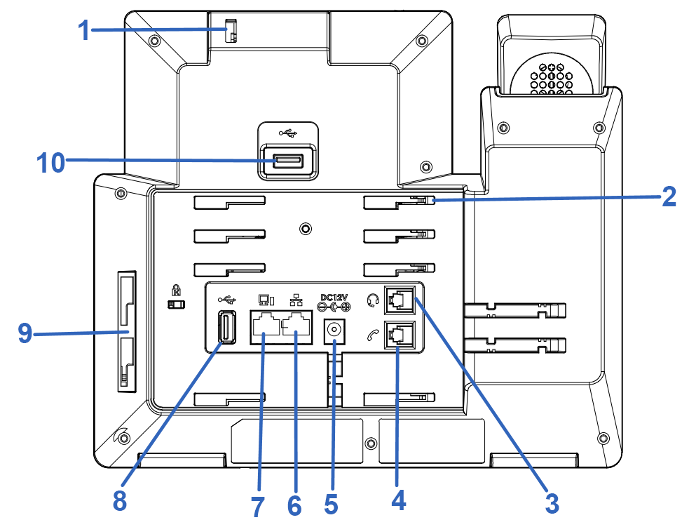
Item | Name | Description |
1 | Camera Adjusting Wheel | Scroll up/down to adjust the camera angle. |
2 | Phone Stand Slot | Put the phone stand from left to right into the slots. |
3 | Handset Port | RJ9 handset connector port. |
4 | Headset Port | RJ9 headset connector port (supporting EHS with Plantronics headset). |
5 | Power Jack | 12V DC Power connector port. |
6 | LAN Port | 10/100/1000Mbps RJ-45 port connecting to Ethernet. PoE/PoE+ is supported |
7 | PC Port | 10/100/1000Mbps RJ-45 port connecting to PC. |
8 | USB Port 2.0 | USB devices can be connected via the USB port. For example, connect a USB flash drive to save captured pictures. |
9 | Side GBX20 Connection Slot | The slots for connecting GXV3450 and GBX20. |
10 | USB 3.0 | USB devices can be connected via the USB port. For example, connect a USB flash drive to save captured pictures. |
GXV3450 Back View
Connecting and Setting Up the GXV34x0
The GXV34x0 can be installed on the desktop using the built-in stand or attached on the wall using the slots for wall mounting.
Using the Phone Stand
- GXV3480
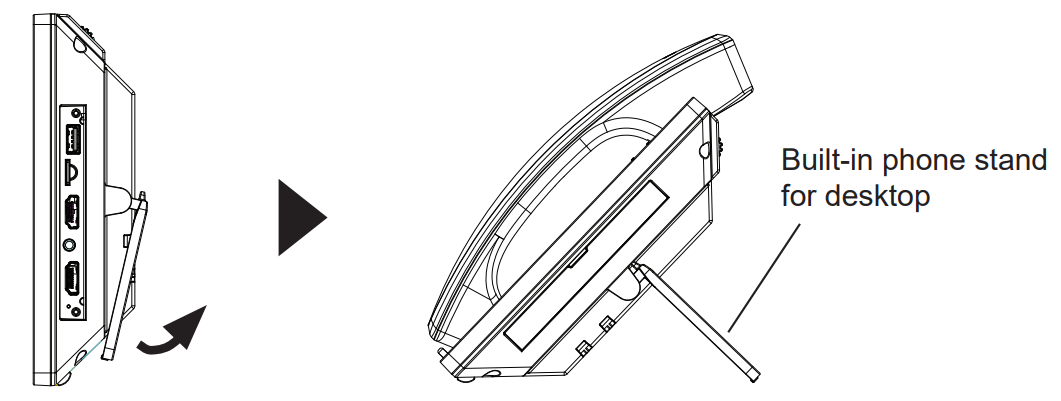
The GXV3380 has a built-in phone stand. To use it, pull out the phone stand handle on the back of the phone. Adjust the angle as preferred and make sure the phone stands still on the desktop. (see figure below).
- GXV3470
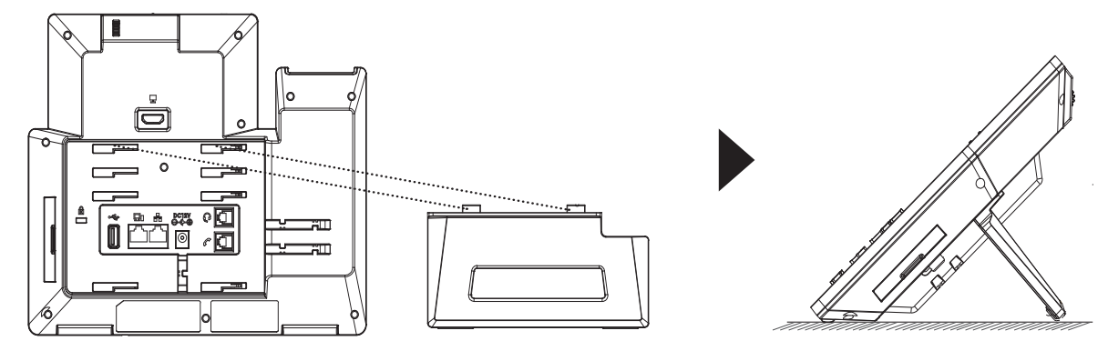
For installing the phone on the table with the phone stand, attach the phone stand by screwing the 4 screws on the upper half side using a Philips head screwdriver (see figure below).

- GXV3450
For installing the phone on the table with the phone stand, attach the phone stand to the bottom of the phone where there is a slot for the phone stand, (upper half, bottom part).
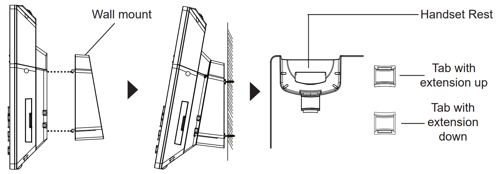
Using the Slots for Wall Mounting
- GXV3480
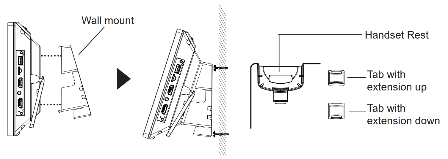
- Attach the wall mount to the slots on the back of the phone;
- Attach the phone to the wall via the wall mount hole;
- Pull out the tab from the handset cradle (see figure below);
- Rotate the tab and plug it back into the slot with the extension up to hold the handset while the phone is mounted on the wall.
- GXV3470
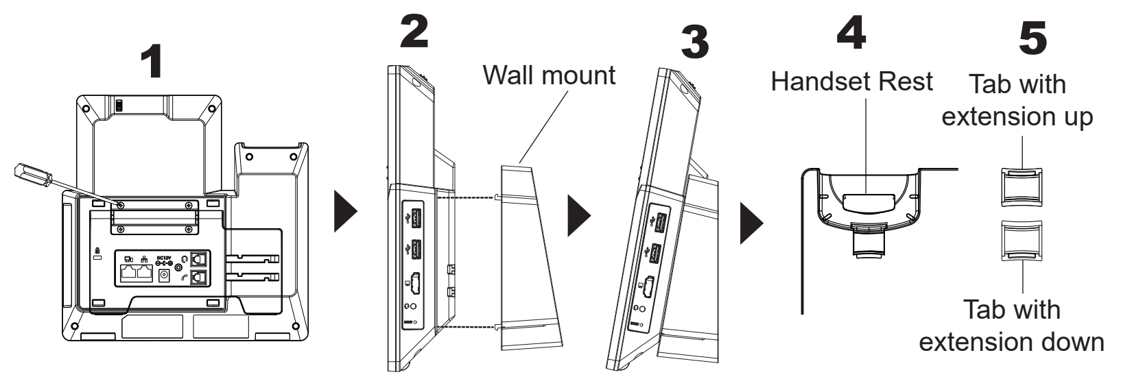
- Remove the desktop bracket by unscrewing the 4 screws with a Philips head screwdriver.
- Attach the wall mount to the slots on the back of the phone.
- Attach the phone to the wall via the wall mount hole.
- Pull out the tab from the handset cradle (see figure below).
- Rotate the tab and plug it back into the slot with the extension up to hold the handset while the phone is mounted on the wall.
- GXV3450
- Attach the wall mount spacers to the slot for wall mount spacers on the back of the phone.
- Attach the phone to the wall via the wall mount hole.
- Pull out the tab from the handset cradle (see figure below).
- Rotate the tab and plug it back into the slot with the extension up to hold the handset while the phone is mounted on the wall.
Connecting the GXV34x0
To setup your GXV34x0, please follow the steps below:
- Connect the handset and main phone case with the phone cord;
- Connect the LAN port of the phone to the RJ-45 socket of a hub/switch or a router (LAN side of the router) using the Ethernet cable;
- Connect the 12V DC output plug to the power jack on the phone; plug the power adapter into an electrical outlet. If PoE switch is used in step 2, this step could be skipped;
- The LCD will display booting up or firmware upgrading information. Before continuing, please wait for the main screen display to show up;
- Using the web configuration interface or from the menu of the touch screen, you can further configure network connection using static IP, DHCP etc.
Cleaning the Phone
For daily dust removal and fingerprint removal, please use the screen cleaning cloth in the factory package to wipe the phone. For some special cases like medical environment, you can use medical alcohol or isopropanol. The steps are as followed:
- Before cleaning the phone, stop using it and disconnect it from the power supply.
- Spray a small amount of disinfectant on screen, camera, handle and other places that are easily touched by users.
- Wipe the phone with screen cleaning cloth.
- Power on until the disinfectant is completely volatilized.
GXV34x0 LCD SETTINGS
The GXV34x0 LCD MENU provides an easy access to the settings on the phone. Some of the settings from Web GUI could be configured via the LCD as well. The following table shows the LCD setting menu options.
Status |
|
Network |
|
Features |
|
Basics |
|
Apps |
|
Advanced |
|
GXV34x0 LCD Settings
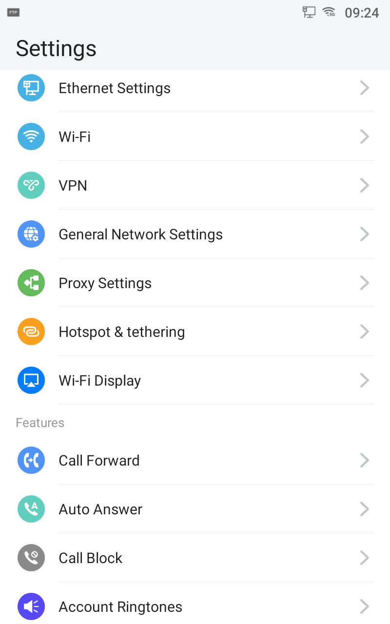
Access LCD Settings
To open the settings menu, you should:
- Tap on
 Settings app on the screen. Or;
 - Swipe down from the top of the home screen to open the notifications panel and hit the
 Settings icon in the top right corner.
 Settings app on the screen. Or;
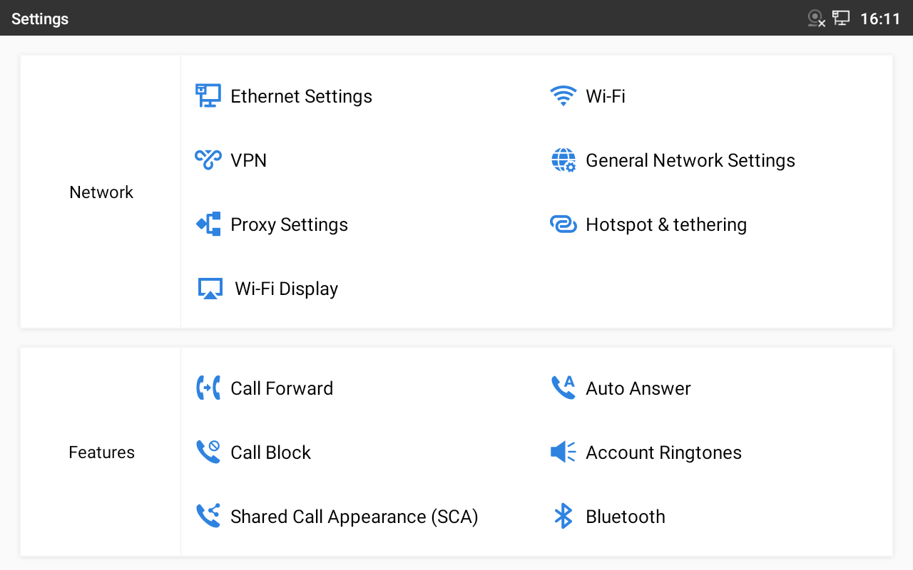
Status
Account Status
This page displays all the available accounts on the phones with their respective status (Registered/Unregistered and Activated/Inactivated).
Network Status
This page displays Network status including IPv4/v6 address, subnet mask, gateway, DNS server…
System Info
This page shows system info including RAM Available Memory, Android Version, System Version, Hardware version …
Storage Status
This page shows device storage status (Storage used and available Storage).
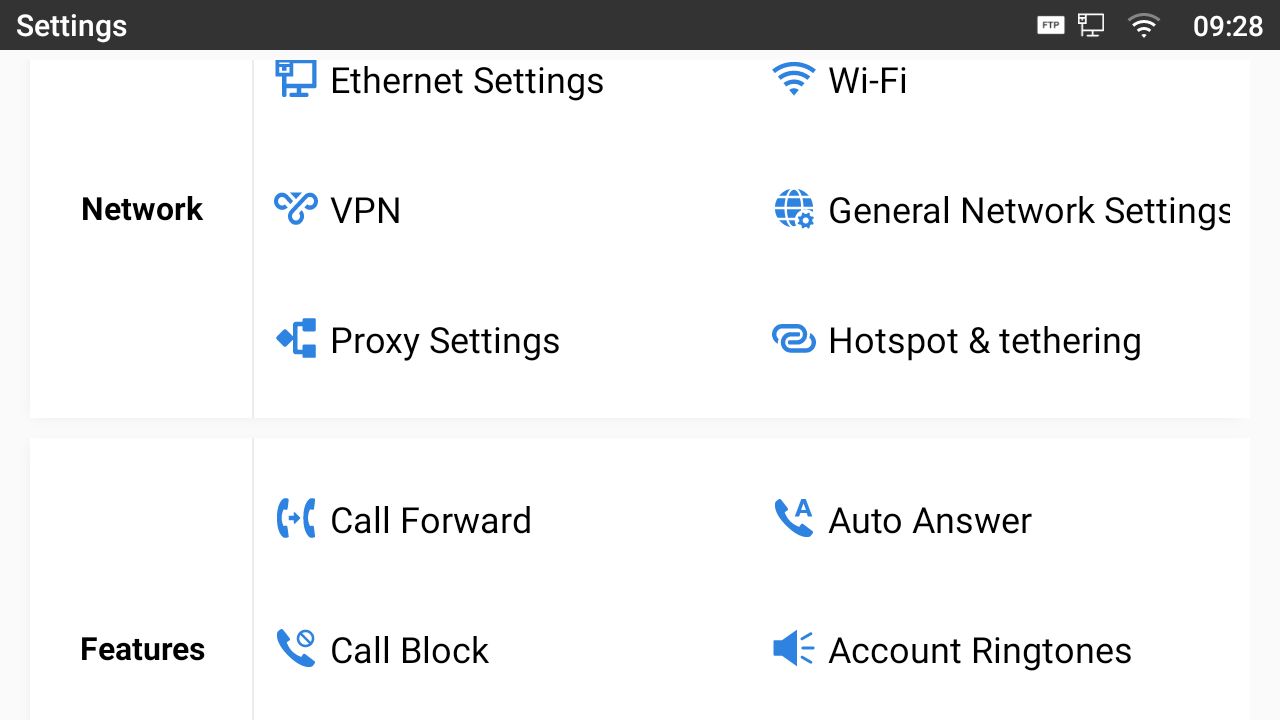
Network
Users can configure Ethernet settings, Wi-Fi, VPN, PPPoE and other advanced network settings here.
Ethernet Settings
- IP Mode: Selects which Internet protocol to use. When both IPv4 and IPv6 are enabled, phone attempts to use preferred protocol first and switches to the other choice if it fails.
- IPv4 Settings: Here user can configure the IPv4 address Type. If DHCP is selected, the phone will get an IP address automatically from the DHCP server in the network. This is the default mode. If Static IP is selected, manually enter the information for IP Address, Subnet Mask, Default Gateway, DNS Server and Alternative DNS server. If PPPoE is selected, type PPPoE Account ID and PPPoE Password provided from the PPPoE server to get authenticated for network access.
- IPv6 Settings: Here user can configure the IPv6 address Type. If Auto-configured is selected, the phone will get an IP address automatically from the DHCP server in the network. This is the default mode. If Static IP is selected, manually enter the information for IP Address, Prefix Length, DNS Server and Alternative DNS server.
- 802.1x mode: This option allows the user to enable/disable 802.1x mode on the phone. The default setting is disabled. To enable 802.1x mode, select from the available modes: EAP-MD5, EAP-TLS and EAP-PEAP
Wi-Fi
- Tap on “Wi-Fi” to turn on/off Wi-Fi connection. By default, it’s turned off.
- Tap on “Wi-Fi Band” to select the band, three options are available: 2.4G & 5G, 2.4G or 5G
- Select the Wi-Fi SSID from the available list then enter the password to get connected, there are also options for a proxy or assigning a static IP.
- In case the Wi-Fi SSID is not showing up on the Available WLAN List or it’s hidden, then scroll down to the bottom of the page and tap on Add network, then enter the name of the SSID and the password to connect.
VPN
Enable / Disable OpenVPN for Android.
General Network Settings
- LLDP
Turn on/off LLDP on the GXV34x0. If turned on, the phone will be able to discover the LAN polices as set up in the switch side to obtain network settings such as VLAN tag, Layer 2 QoS 802.1p priority and Layer 3 QoS in a plug-and-play manner.
- LLDP TX Interval
Specifies the time interval, in seconds, between successive LLDP-MED transmission cycles
- Layer 3 SIP QoS
This field defines the layer 3 QoS parameter for SIP packets.
This is the value used for IP Precedence, Diff-Serv or MPLS. The Default value is 26.
- Layer 3 Audio QoS
This field defines the layer 3 QoS parameter for audio packets. This is the value used for IP Precedence, Diff-Serv or MPLS. The Default value is 46.
- Layer 3 Video QoS
This field defines the layer 3 QoS parameter for video packets. This is the value used for IP Precedence, Diff-Serv or MPLS. The Default value is 34.
- Applied to the Second Layer of Data QoS 802.1Q/VLAN tag (Ethernet)
This field contains the value used for layer 2 VLAN tagging for the Ethernet network.
The Default value is 0.
- Applied to the Second Layer of Data QoS 802.1p Priority (Ethernet)
This assigns the priority value of the Layer 2 QoS packets on the Ethernet Network.
The Default value is 0.
Proxy Settings
For some network setup, it is required to connect to the Internet via proxy server. Manually configure “HTTP/HTTPS Proxy Hostname“, “HTTP/HTTPS Proxy Port” and “Bypass Proxy For” in proxy settings for the phone to get Internet connection successfully.
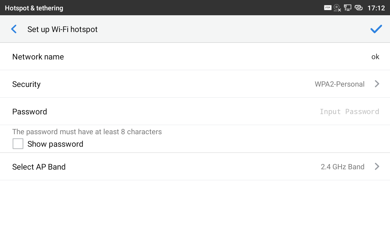
Hotspot & tethering
The GXV34x0 phones can serve as a Wi-Fi access point for other devices to provide wireless access to the network if the Portable Wi-Fi hotspot is turned on.
- Turn on hotspot by tapping on “Portable Wi-Fi hotspot“. Icon
 will show on the top status bar.
 - Tap on “Set up Wi-Fi hotspot” to configure network SSID, security type and password. Please make sure the password has at least 8 characters. Otherwise, users won’t be able to save the setting.
- On the other device that needs Wi-Fi access, turn on Wi-Fi, look for the SSID of the GXV34x0 hotspot and enter authentication information to get connected.
Wi-Fi Display
Wi-Fi Display allows mirroring the screen of GXV34x0 to any device that supports Wi-Fi display mirroring functionality for example like smart TVs…
Features
In this menu, users can configure different features related to each account of the active accounts:
Call Forward
The incoming call to a SIP account can be forwarded to another account using different rules.
Call Forward: Call forwarding feature is disabled. This is the default setting. Tab to activate.
Call Forward Type:
- Unconditional: Forward all calls to a number.
- Time based: Set the time range and number to be forwarded the calls to. In this time range, calls are forwarded to the number specified in “In Time Forward To“; out of this time range, calls are forwarded to the number specified in “Out Time Forward To“.
- Others: Configure Call forward when the phone is Busy or on DND or based on No Answer Out.
Auto Answer
IF Enabled and set to “Always“, the phone will automatically turn on the speaker phone to answer all incoming calls.
If enabled and set to “Enable Intercom/Paging“, the phone will answer the call based on the SIP info header sent from the server/proxy.
By default, it’s turned off.
Call Block
Blacklist: This menu allows configuring a black list of number that will be blocked from calling the phone, users can either enter the numbers to block manually, from contacts or from call history.
Block Anonymous Calls: when enabled the phone rejects all the anonymous calls, users can choose on which account this setting is to be applied
Account Ringtones
Select a ringtone for the incoming call to the SIP account chosen. The system ringtone is set by default.
Shared Call Appearance (SCA)
Shared Call Appearance (SCA): Enable or disable SCA on the account.
Enable Barge-in: If set to “Yes”, the user could barge into an active call on a shared line.
Auto Fill Call Park Code: If set to “Yes”, the configured “Call Park Service Code” will be automatically filled in on the phone’s dial pad when picking up the parked call. This is used when “Special Mode” is set to “BroadSoft” (from web UI or provisioning) and “Enable SCA” is set to “Yes”.
Call Park Service Code: Configure the retrieving feature code for call parking. If “Auto Fill Call Park Code” is set to “Yes”, this call park service code will be automatically filled in on the phone’s dial pad when picking up the parked call. This is used when “Special Mode” is set to “BroadSoft” (from web UI or provisioning) and “Enable SCA” is set to “Yes”.
Line-size Timeout (s): Configure the time for the line can be seized (in seconds) when using shared line. The default setting is 15 seconds. For Shared Call Appearance, phone will send a SUBSCRIBE-request for the line-seize event package whenever a user attempts to take the shared line off hook. “Line Seize Timeout” is the line-seize event expiration timer.
Bluetooth
Bluetooth: Tap on “Bluetooth” to turn on/off Bluetooth connection. By default, it’s turned off.
Enable Handsfree Mode: Tap on “Enable handsfree mode” to activate it.
Show received files: Shows the Transfer history of Bluetooth files
Additional Settings: This menu is available only when the Bluetooth is enabled:
Device Name. Tap to change the name of the GXV34x0, which is displayed on other Bluetooth devices when discovered. By default, it’s “GXV34x0_XXXXXX” where “XXXXXX” are the last 6 digits of the phone’s MAC address plus 2, for e.g. If the phone’s last 6 digits of MAC address is D33B4C, the Bluetooth’s name would be GXV34x0_D33B4E.
Visibility timeout. Tap to select the timeout interval among “2 minutes”, “5 minutes”, “1 hour” or “never”. By default, the visibility timeout is 2 minutes.
Visibility to nearby Bluetooth devices. Sets the visibility of the phone to other Bluetooth devices. Normally this option is enabled during pairing process so that other Bluetooth devices can discover the GXV34x0.
Available devices: This section will show the available devices for pairing. Tap on ![]() to initiate scan process on the GXV34x0 to discover the Bluetooth devices within the range.
to initiate scan process on the GXV34x0 to discover the Bluetooth devices within the range.
Virtual Background
This setting defines the virtual background that will be displayed by default when a video call is initiaed.
Dynamic Lock
In this setting, the user enables a security feature called dynamic lock, this feature allows the GXV34xx phone to be automatically locked once the cellphone paired with the GXV34xx through bleutooth is out of range.
Basics
Sound
Use the Voice settings to configure the phone’s sound mode, volume, ring tone and notification tone.
- Silent mode. Tap on it to turn on/off the sound from speaker when there is an incoming call.
- HDMI. Only when plugging in HDMI cable. If enabled, the media channel will switch to HDMI.
- Media Volume. Adjust the sound volume for media audio
- Alarm Volume. Adjust the alarm ring volume
- Ring Volume. Adjust the phone ringing volume
- Ringtone. Select phone’s ringtone for incoming call.
- Default Notification Ringtone. Select notification ringtone.
- Default Alarm Ringtone. Select the alarm ringtone
- Other Sounds. Enable/disable Dial pad tones, Screen Locking Sounds, Touch Sounds and Button Tones.
Display
- Brightness. Tap on Brightness and scroll left/right to adjust the LCD brightness.
- Screen timeout. Tap to open the dialog to set the screen timeout interval.
- Screensaver timeout. Tap to set the screensaver timeout interval.
- Screensaver.
- Screensaver: If screensaver is set, please tap on
 to set use a network images or use local or images as screensaver and set the Animation Interval between the images.
 - Clock: If the clock is set as screensaver, tap on and set the clock style and the Night Mode
- Screensaver: If screensaver is set, please tap on
- Font size. Tap on it to adjust the font size for LCD screen.
- Use Server Wallpaper: Tap to activate Server Wallpaper.
- Server Wallpaper Path: set the wallpaper based on server.
Language & Keyboard
Language: Tap to open the list of chosen languages, Language Number 1 is the language used on the phone. Tap on Add a Language to add more languages to the list.
Keyboards: Set up default input method for on-screen and physical keyboard and the different parameters of the related to the Keyboard use. The default input method is Android Keyboard.
- On-screen keyboard:
- Android keyboard (AOSP): Set up the language used on Android keyboard and configure its different parameters including sound, auto-correction, word suggestion and so on.
- Manage on-screen Keyboards. Tap on the + sign to choose which keyboard to use on the phone.
- Physical Keyboard: When the physical keyboard is connected to the phone, users will have the possibility to choose a keyboard among the available ones on the virtual keyboard:
- Use on-screen keyboard: this option gives the possibility if keep showing the virtual keyboard even if the physical one is connected to the phone.
- Keyboard shortcuts: Display available shortcuts.
Tools:
- Spell checker. Configure whether to check spellings and select the language to check.
- Autofill Service: Select or Add a service for autofill (usernames, password…).
- Personal dictionary. Add new words to user’s dictionary so that they won’t be displayed as error in the text.
- Pointer Speed: Adjust the sensitivity of the mouse pointer.
Date & Time
- Enable and use specified NTP server address. Assign the URL or IP Address of NTP Server. The default NTP Server used is pool.ntp.org
- Set date. Set the current date.
- Set time. Set the time manually.
- Select time zone. Select the time zone.
- Use 24-hour format. Check/uncheck to display the time using 24-hour time format or not. For example, in 24-hour format, 13:00 will be displayed instead of 1:00 p.m.
- Select date format. Select the format of year, month and day for the date to be displayed.
Security Settings
- Device Security-Screen lock: Set up pattern or password for screen lock. Wizard will be provided to set up the pattern. The screen will be locked after booting up or the screen is off (i.e., screensaver screen activated, or manually slide down Status Bar🡪Screen Off
 to turn off LCD). Users will then be required to enter password or pattern to login. When the screen is locked, users can still be able to answer or reject incoming call.
 - Privacy-Show passwords: Check/uncheck to show/hide letters when user’s type screen lock password instantly.
- Device Admin–Device admin apps: View or deactivate device administrators.
- Credentials Storage
- Trusted CA Credentials. Display trusted CA certificates for system or user. Users can tap on the certificate to check the credential details or disable it.
- User Credentials. View and modify stored credentials
- Advanced
- Trust Agents. View or deactivate trust agent.
- Apps with usage access. Manage what apps have access to app-usage data on your device.
Peripherals
Plug in RJ9/EHS Headset. Switch the media channel to RJ9 headset after plugging in the corresponding port.
Accounts
Add a system account to synchronize contacts calendars and other information.
Power Information
PoE Power Supply notification. If enabled, the phone’s system will display a notification of disabling USB, HDMI-in and HDMI-out when PoE is used. If disabled, the notification will not be shown.
PoE Power Supply Limitation. When enabled, the device would display a warning that it is powered by PoE, and using USB interface or Type-C interface will cause insufficient power supply and reboot.
Accessibility
Services: installed services will be listed here
System:
- Magnification: Android built in tool to magnify the screen with triple tap.
- Autoclick (dwell timing): works with a connected mouse. user can set the mouse cursor to click automatically when the cursor stops moving for a certain amount of time.
- Speak passwords: read out passwords using the in-built screen reader, Talkback. This makes is easier for users to fill in passwords.
- Large mouse pointer: makes the mouse pointer larger
- Touch & hold delay: select the touch and hold delay
Display:
- Color inversion: Tap to invert colors
- Color correction: allows to adjust how colors are displayed on the device
Reboot the Phone
Press to reboot the phone. A confirmation window will pop up to Cancel or go on with the reboot.
Apps
Application Management
Tap on an application, a process or a service to open it. The Application Info screen for each application lists its name, version, size, etc. Depending on the app, it may also include options for managing the application’s data, forcing the application to stop, and disabling the application. Usually the options are:
- Tap the “Force stop” softkey to stop an application forcefully. This setting might not be valid for some applications.
- Tap the “Stop” softkey to stop an application gracefully. This setting might not be valid for some applications.
- Tap the “Disable” softkey to disable the application. Users could tap on “Enable” to turn it back on again. This usually applies to the built-in applications.
- Tap the “Uninstall” softkey to uninstall the applications.
- Storage provides storage information that an application uses on the phone. Tap “Clear data” to delete an application setting and other data. This setting might valid for some applications. If the application stores data in a temporary space of the phone’s memory, “Cache” lists how much information is stored.
- Tap on “Clear cache” to clear the cache.
- “Permissions” lists information of the data that the app has access to. For example, the application might access the location information, storage, phone calls etc.
- “Open by default“. If the application is configured to launch certain file type by default, tap on “Clear defaults” to reset this.
- If an application is misbehaving, tap on “Report” softkey (if available) to send the developer information for the application.
- Memory will show the memories used on the phone by the applications
- Modify System settings gives the application the permission to modify the system settings
- Store provides Information about the Install source of the App
Default Application
This page allows to set default applications to launch with certain actions. Default applications can be set for following actions:
- Opening Links. Select which application to use as default when clicking on a web link (browser); when opening a picture (gallery) or when opening a music file (music).
- Assist & Voice Input. Select a default application if previously installed.
- Home app. Select default launcher application if already installed.
- Browser app. Select default browser if more than one is installed.
- Emergency app. Select emergency default application if already installed.
Notification Center
Tap on an application, process or service to open it. The notification Info screen for each application lists supported actions and allow user to activate/deactivate each notification. Following notifications can be configured (supported notifications depend on the applications):
Advanced
Account Settings
Account Settings page allows to configure SIP settings for each account. Tap on Account# to access the settings, when configured press ✔ sign (on the top right corner) to confirm the changes, or press back button to cancel them. Users can press Empty configuration on the bottom of the page to clear all the settings. Following settings can be configured for each account. Refer to [Account/SIP/General Settings] for description of each option.
- Account Activation.
- Account Name.
- SIP Server.
- SIP User ID.
- SIP Authentication ID.
- SIP Authentication Password.
- Outgoing Proxy Server.
- Voicemail access number.
- Outgoing call display name.
System Update
This page allows to initiate upgrade process by checking if a new firmware is available in the configured firmware server path, and then upgrading if available. Users can press![]() Settings to configure Firmware/Provisioning settings directly from the phone’s LCD. Following settings can be configured from this screen:
Settings to configure Firmware/Provisioning settings directly from the phone’s LCD. Following settings can be configured from this screen:
- Firmware upgrade and configuration file detection. This will send a request to firmware and provisioning server to upgrade/provision the phone if the files are available on the servers.
- Firmware:
- Upgrade Mode: This field allows the user to choose the firmware upgrade method: TFTP, HTTP or HTTPS.
- HTTP/HTTPS username: The user name for the HTTP/HTTPS server if set up on the server.
- HTTP/HTTPS password: The password for the HTTP/HTTPS server if set up on the server.
- Firmware Server Path: This defines the server path for the firmware server. It can be different from the configuration server for provisioning.
- Config:
- Upgrade mode: This field allows the user to choose the provisioning method: TFTP, HTTP or HTTPS.
- HTTP/HTTPS username: The user name for the HTTP/HTTPS server if set up on the server.
- HTTP/HTTPS password: The password for the HTTP/HTTPS server if set up on the server.
- Config Server Path: This defines the server path for the provisioning server. It can be different from the firmware server.
Syslog
- Syslog level: Select the level of logging for syslog. The default setting is “None”. There are 4 levels: DEBUG, INFO, WARNING and ERROR.
- System log protocol: Select the protocol of syslog (UDP or SSL/TLS).
- Syslog server address: The URL/IP address for the syslog server. If the GXV34x0 has network connection, the phone will send the syslog packets to this server address.
- System log keyword filter: Only send the syslog with keyword, multiple keywords are separated by comma. Example: set the filter keyword to “SIP” to filter SIP log.
System Security
- Disable Web Login: This disables web GUI access.
- Developer Mode. To enable/disable developer mode.
- Revoke debugging authorizations. To Revoke access to debugging from all computers previously authorized.
- Factory Reset. Restore default settings.
GXV34x0 WEB GUI SETTINGS
The GXV34x0 embedded Web server responds to HTTP/HTTPS GET/POST requests. Embedded HTML pages allow users to configure the application phone through a Web browser such as Microsoft’s IE, Mozilla Firefox, Google Chrome and etc.
Status Page Definitions
Status/Account Status
| Account | 16 SIP accounts on the phone. |
| SIP User ID | SIP User ID for the account. |
| SIP Server | URL or IP address, and port of the SIP server. Note: this parameter also supports domain string such as “grandstream”. |
| Status | Registration status for the SIP account. |
| GS Wave | Users can click “Enter” button to open GS Wave web page. |
Status/Network Status
| MAC Address | Global unique ID of device, in HEX format. The MAC address will be used for provisioning and can be found on the label coming with original box and on the label located on the back of the device. |
| NAT Type | Type of NAT connection used by the phone. |
| IPv4 | |
| IPv4 Address Type | Configured address type: DHCP, Static IP or PPPoE. |
| IPv4 Address | IP address of the phone. |
| Subnet Mask | Subnet mask of the phone. |
| Default Gateway | Default gateway of the phone. |
| DNS Server 1 | DNS Server 1 of the phone. |
| DNS Server 2 | DNS Server 2 of the phone. |
| IPv6 | |
| IPv6 Address Type | Configured address type: DHCP, Static IP or PPPoE. |
| IPv6 Address | IPv6 address of the phone. |
| IPv6 Gateway | IPv6 gateway of the device. |
| IPv6 DNS Server 1 | IPv6 DNS Server 1 of the phone. |
| IPv6 DNS Server 2 | IPv6 DNS Server 2 of the phone. |
Status/System Info
| Product Model | Product model of the phone |
| Hardware Version | Hardware version number. |
| Part Number | Product part number. |
| Serial Number | Serial Number of the phone. |
| System Version | Firmware version ID. This is the main software release version, which is used to identify the software system of the phone. |
| Boot Version | Booting code version |
| Kernel Version | The kernel version |
| CPE Version | The CPE version |
| Device Individual Certificate | Device Individual Certificate of the device. |
| System Up Time | System up time since the last reboot. |
Account Page Definitions
GXV34x0 phones has 16 lines that can be configured to accommodate 16 independent SIP accounts. Each account has an individual configuration page.
Account/General Settings
| Account Registration | |
| Account Active | Indicates whether the account is active. The default value for the first account is “Yes”. |
| Account Name | Configures the name associated with each account to be displayed on the LCD. |
| SIP Server | Specifies the URL or IP address, and port of the SIP server. This should be provided by VoIP service provider (ITSP). |
| SIP User ID | Configures user account information provided by your VoIP service provider (ITSP). It’s usually in the form of digits similar to phone number or actually a phone number. |
| SIP Authentication ID | Configures the SIP service subscriber’s Authenticate ID used for authentication. It can be identical to or different from the SIP User ID. |
| SIP Authentication Password | Configures the account password required for the phone to authenticate with the ITSP (SIP) server before the account can be registered. After saving, it will appear as hidden for security purpose. |
| Display Name | Specifies the SIP server subscriber’s name (optional) that will be used for Caller ID display. The configured content will be included in the From, Contact and P-Preferred-Identity headers of SIP INVITE message. |
| Tel URI | Indicates E.164 number in “From” header by adding “User=Phone” parameter or using “Tel:” in SIP packets, if the phone has an assigned PSTN Number.
Please consult your carrier before changing this parameter. Default is “Disabled”. |
| Voice Mail Access Number | Sets if the phone system allows users to access the voice messages by pressing the MESSAGE key on the phone. This ID is usually the VM portal access number. For example, in UCM6xxx IPPBX, *97 could be used. |
| Network Settings | |
| Outbound Proxy | Configures the IP address or the domain name of the primary outbound proxy, media gateway or session border controller. It’s used by the phone for firewall or NAT penetration in different network environments. If a symmetric NAT is detected, STUN will not work and only an outbound proxy can provide a solution |
| Secondary Outbound Proxy | Sets IP address or domain name of the secondary outbound proxy, media gateway or session border controller. The phone system will try to connect the Secondary outbound proxy only if the primary outbound proxy fails. |
| DNS Mode | Defines which DNS service will be used to lookup IP address for SIP server’s hostname. There are three modes:
To locate the server by DNS SRV set this option to “SRV” or “NATPTR/SRV”. Default setting is “A Record”. |
| Maximum Number Of SIP Request Retries | This setting configures the maximum number of retries for the device to send requests to the server. In DNS SRV configuration, if the destination address does not respond, all request messages are resent to the same address according to the configured retry times. Valid range: 1-10. |
| DNS SRV Failover Mode | Configures the preferred method for DNS SRV failover. There are Three DNS SRV Failover mode:
|
| Failback Expiration(m) | This option is configured when DNS SRV failover mode “Failback follows failback expiration timer” is chosen. It specifies the duration (in minutes) since failover to the current SIP server or Outbound Proxy before making failback attempts to the primary SIP server or Outbound Proxy. Valid range: 1 – 64800 |
| Register Before DNS SRV Fail-over | To set register before DNS SRV Fail-over. The default value is “Yes” |
| NAT Traversal | Specifies which NAT traversal mechanism will be enabled on the phone system. It can be selected from the dropdown list:
If the outbound proxy is configured and used, it can be set to “NAT NO”. If set to “STUN” and STUN server is configured, the phone system will periodically send STUN message to the SUTN server to get the public IP address of its NAT environment and keep the NAT port open. STUN will not work if the NAT is symmetric type. If set to “Keep-alive”, the phone system will send the STUN packets to maintain the connection that is first established during registration of the phone. The “Keep-alive” packets will fool the NAT device into keeping the connection open and this allows the host server to send SIP requests directly to the registered phone. If it needs to use OpenVPN to connect host server, it needs to set it to “VPN”. If the firewall and the SIP device behind the firewall are both able to use UPNP, it can be set to “UPNP”. The both parties will negotiate to use which port to allow SIP through. The default setting is “Keep-alive”. |
| Proxy-Require | Adds the Proxy-Required header in the SIP message. It is used to indicate proxy-sensitive features that must be supported by the proxy. Do not configure this parameter unless this feature is supported on the SIP server. |
Account/SIP Settings
| SIP Basic Settings | |
| SIP Registration | Allows the phone system to send SIP REGISTER messages to the proxy/server. The default setting is “Yes”. |
| Unregister before New Registration | Controls whether to clear SIP user’s information by sending un-register request to the proxy server.
The default setting is “Instance”. |
| Register Expiration (m) | Configures the time period (in minutes) in which the phone refreshes its registration with the specified registrar. The default setting is 60. The maximum value is 64800 (about 45 days). |
| Subscribe Expiration (m) | Specifies the frequency (in minutes) in which the phone refreshes its subscription with the specified registrar. The maximum value is 64800 (about 45 days). Default value is 60. |
| Re-register before Expiration (s) | Specifies the time frequency (in seconds) that the phone sends re-registration request before the Register Expiration. The default setting is 0. The range is from 0 to 64,800. |
| Registration Retry Wait Time (s) | Configures the time period (in seconds) in which the phone will retry the registration process in the event that is failed. The default setting is 20. The maximum value is 3600 (1 hour). |
| Add Auth Header on Initial REGISTER | Configure if the SIP account needs to add Auth header in RE-REGISTER.
|
| Enable SIP OPTIONS Keep Alive | Enables SIP OPTIONS to track account registration status so the phone will send periodic OPTIONS message to server to track the connection status with the server. The default setting is “No”. |
| SIP OPTIONS Keep Alive Interval (s) | Configures the time interval when the phone sends OPTIONS message to SIP server. The default setting is 30 seconds, which means the phone will send an OPTIONS message to the server every 30 seconds. The default range is 1-64800. |
| SIP OPTIONS Keep Alive Maximum Tries | Configures the maximum times of sending OPTIONS message consistently from the phone to server. Phone will keep sending OPTIONS messages until it receives response from SIP server. The default setting is “3”, which means when the phone sends OPTIONS message for 3 times, and SIP server does not respond this message, the phone will send RE-REGISTER message to register again. The valid range is 3-10. |
| Subscribe for MWI | Configures the phone system to subscribe voice message service. If it is set to “Yes”, the phone system will periodically send SIP SUBSCRIBE message for Message Waiting Indication service. GXV3480 phone system supports both synchronized and non-synchronized MWI. The default setting is “No”. |
| Use Privacy Header | Determines if the Privacy header will be presented in the SIP INVITE message and if it includes the caller info in this header. If it is set to “Default”, the Privacy Header will be omitted in INVITE when “Huawei IMS” special feature is active. If set to “Yes”, it will always be presented. If set to “No”, it will always be omitted. The default setting is “Default”. |
| Use P-Preferred-Identity Header | Specifies if the P-Preferred-Identity Header will be presented in the SIP INVITE message. If set to “default”, the P-Preferred-Identity Header will be omitted in SIP INVITE message when “Huawei IMS” special feature is active. If set to “Yes”, the P-Preferred-Identity Header will always be presented. If set to “No”, it will be omitted. The default setting is “Default”. |
| Use P-Access-Network-Info Header | Enables/disables the use of P-Access-Network-Info header in SIP request. When disabled, the SIP message sent from the phone will not include the selected header. Default setting is “No”. |
| Use P-Emergency-Info Header | Enables/disables the use of P-Emergency-Info header in SIP request. When disabled, the SIP message sent from the phone will not include the selected header. Default setting is “No”. |
| Use Mac Header Add MAC in User-Agent |
|
| SIP Transport | Determines which network protocol will be used to transport the SIP message. It can be selected from TCP/UDP/TLS. Default setting is “UDP”. |
| Local SIP Port | Determines the local SIP port used to listen and transmit. The default setting is 5060 for Account 1, 5062 for Account 2, 5064 for Account 3, 5066 for Account 4, 5068 for Account 5, and 5070 for Account 6. The valid range is from 5 to 65535. |
| SIP URI Scheme When Using TLS | Defines which SIP header, “sip” or “sips”, will be used if TLS is selected for SIP Transport. The default setting is “sip”. |
| Use Actual Ephemeral Port in Contact with TCP/TLS | Determines the port information in the Via header and Contact header of SIP message when the phone system use TCP or TLS. If set to No, these port numbers will use the permanent listening port on the phone. Otherwise, they will use the ephemeral port for the particular connection. The default setting is “No”. |
| Support SIP Instance ID | Determines if the phone system will send SIP Instance ID. The SIP instance ID is used to uniquely identify the device. If set to “Yes”, the SIP Register message Contact header will include +sip.instance tag. The default setting is “Yes”. |
| SIP T1 Timeout | Defines an estimate of the round-trip time of transactions between a client and server. If no response is received in T1, the figure will increase to 2*T1 and then 4*T1. The request re-transmit retries would continue until a maximum amount of time define by T2. The default setting is 0.5 sec. |
| SIP T2 Interval | Specifies the maximum retransmit time of any SIP request messages (excluding the SIP INVITE message). The re-transmitting and doubling of T1 continues until it reaches the T2 value. The default setting is 4 sec. |
| SIP Timer D Interval | Defines the amount of time that the server transaction can remain when unreliable response (3xx-6xx) received. The valid value is 0-64 seconds. The default value is 0. |
| Remove OBP from Route | Configures the phone system to remove the outbound proxy URI from the Route header. This is used for the SIP Extension to notify the SIP server that the device is behind a NAT/Firewall, the user can choose to set the option to “Enabled”, “Disabled”, and “Always” If it is set to “Enabled”, it will remove the Route header from SIP requests. The default setting is “Disabled”. Note: “Enabled” works for unknown NAT and other NAT networks. “Always” works for all kinds of networks. |
| Enable 100rel Use route set in NOTIFY (Follow RFC 6665) | Actives PRACK (Provisional Acknowledgment) method. PRACK improves the network reliability by adding an acknowledgement system to the provisional Responses (1xx). It is set to “Yes”, the phone system will response to the 1xx response from the remote party. Default is “No”. Configures whether to use route set in NOTIFY (follow RFC 6665). If enabled, the Request URI of the refresh/cancel subscription will use the URI in the received NOTIFY Contact (RFC 6665); otherwise, the URI in the previously subscribed 200 OK Contact will be used. |
| Session Timer | |
| Enable Session Timer | Allows the phone system to use the session timer, when set to “Yes”, it will be added in the SIP INVITE message to notify the server. |
| Session Expiration (s) | Configures the phone system’s SIP session timer. It enables SIP sessions to be periodically “refreshed” via a SIP request (UPDATE, or re-INVITE). If there is no refresh via an UPDATE or re-INVITE message, the session will be terminated once the session interval expires. Session Expiration is the time (in seconds) where the session is considered timed out, provided no successful session refresh transaction occurs beforehand. The default setting is 180. The valid range is from 90 to 64800. |
| Min-SE (s) | Determines the minimum session expiration timer (in seconds) if the phone act as a timer refresher. The default setting is 90. The valid range is from 90 to 64800. |
| UAC Specify Refresher | Sets which party will refresh the active session if the phone makes outbound calls. If it is set to “UAC” and the remote party does not support Refresher feature, the phone system will refresh the active session. If it is set to “UAS”, the remote party will refresh it. If it is set to “Omit”, the header will be omitted so that it can be selected by the negotiation mechanism. The default setting is “Omit”. |
| UAS Specify Refresher | Specifies which party will refresh the active session if the phone receives inbound calls. If it is set to “UAC”, the remote party will refresh the active session. If it is set to “UAS” and the remote party does not support refresh feature, the phone system will refresh it. The default setting is “UAC”. |
| Caller Request Timer | Sets the caller party to act as refresher by force. If set to “Yes” and both party support session timers, the phone will enable the session timer feature when it makes outbound calls. The SIP INVITE will include the content “refresher=uac”. The default setting is “No”. |
| Callee Request Timer | Sets the callee party to act as refresher by force. If set to “Yes” and the both parties support session timers, the phone will enable the session timer feature when it receives inbound calls. The SIP 200 OK will include the content “refresher=uas”. The default setting is “No”. |
| Force Timer | Configures the session timer feature on the phone system by force.
The default setting is “No”. |
| Force INVITE | Sets the SIP message type for refresh the session. If it is set to “Yes”, the Session Timer will be refreshed by using the SIP INVITE message. Otherwise, the phone system will use the SIP UPDATE or SIP OPTIONS message. Default is “No”. |
Account/Codec Settings
Preferred Audio Codec | |
Preferred Audio Codec | Lists the available and enabled Audio codecs for this account. Users can enable the specific audio codecs by moving them to the selected box and set them with a priority order from top to bottom. G.722 |
Codec Negotiation Priority | Configures the phone to use which codec sequence to negotiate as the callee. When set to “Caller”, the phone negotiates by SDP codec sequence from received SIP Invite; When set to “Callee”, the phone negotiates by audio codec sequence on the phone. The default setting is “Callee”. |
Use First Matching Vocoder in 200OK SDP | Configures the phone to use the first matching codec in the 200OK message. |
ILBC Frame Size | Sets the ILBC (Internet Low Bitrate Codec) frame size if ILBC is used. Users can select it from 20ms or 30ms. |
G726-32 ITU Payload | Configures G726-32 payload type for ITU packing mode. Payload 2 is static and payload dynamic is dynamic. The default setting is “2”. |
G726-32 Dynamic PT | Specifies the G726-32 payload type, and the valid range is 96 to 126. The default setting is “126”. |
Opus Payload Type | Defines the desired value (96-126) for the payload type of the Opus codec. |
DTMF | Specifies the mechanism to transmit DTMF (Dual Tone Multi-Frequency) signals. There are 3 supported modes: in audio, RFC2833, or SIP INFO.
The default setting is “RFC2833”. |
DTMF Payload Type | Configures the RTP payload type that indicates the transmitted packet contains DTMF digits. Valid range is from 96 to 126. Default value is 101. |
Enable Audio RED with FEC | If set to “Yes”, FEC will be enabled for audio call. The default setting is “No”. |
Audio FEC Payload Type | Configures audio FEC payload type. The valid range is from 96 to 126. The default value is 121. |
Audio RED Payload Type | Configures audio RED payload type. The valid range is from 96 to 126. The default value is 124. |
Silence Suppression | Enables the silence suppression/VAD feature. If it is set to “Yes”, when silence is detected, a small quantity of VAD packets (instead of audio packets) will be sent during the period of no talking. If set to “No”, this feature is disabled. The default setting is “No”. |
Voice Frames Per TX | Configures the number of voice frames transmitted per packet. When configuring this, it should be noted that the “ptime” value for the SDP will change with different configurations here. This value is related to the codec used and the actual frames transmitted during the in payload call. For end users, it is recommended to use the default setting, as incorrect settings may influence the audio quality. The default setting is 2. |
Preferred Video Codec | |
Preferred Video Codec | Lists the available and enabled Video codecs for this account. Users can enable the specific video codecs by moving them to the selected box and set them with a priority order from top to bottom. This configuration will be included with the same preference order in the SIP SDP message.
|
Enable Video FEC | When enabled, the video sender will temporarily allocate part of the bandwidth to one data channel to send FEC data to system, thus to improve the video quality the receiver gets. Enabling this function will take up part of bandwidth and reduce call rate. |
Enable RFC5168 Support | Enables/disables RFC5168 mechanism for video calls. RFC5168 allows SIP party to request the sender to refresh its video frame in H.264, or refresh the full picture in VP8. |
Video FEC Mode | If set to 0, FEC is not sent by separate port. If set 1, FEC is sent by separate port. |
FEC Payload Type | Configures FEC payload type. The range is 96-126. Default setting is 120. |
Packetization Mode | Set video packetization mode. If set to “Single NAL Unit Mode”, the packetization mode will be negotiated as single NAL unit mode when dial video calls, if the other party does not support the negotiation, then single NAL unit mode will be used for video encoding by default. If set to “Non-Interleaved Mode”, the packetization mode will be negotiated as Non-interleaved mode when dial video calls, If the other party does not support negotiation, then the Non-interleaved mode will be used for for video encoding by default; If set to “Prefer Non-Interleaved Mode”, the packetization mode will be negotiated as prefer Non-interleaved mode when dial video calls, if the other party does not support the negotiation, then prefer Non-interleaved mode will be used for video encoding by default. |
H.264 Image Size | Sets the H.264 image size. It can be selected from the dropdown list. 720P
Note: For some network environment, the default setting “720P” might be too high that causes no video or video quality issue during video call. In this case, please change “H.264 Image Size” to “VGA” or “CIF” and change “Video Bit Rate” to “384kbps” or lower. The default setting is 720P. |
Use H.264 Constrained Profiles | Configures that whether to set H.264 constrained profiles. The default setting is “No”. |
H.264 Profile Type | Selects the H.264 profile type from the dropdown list.
Note: Lower levels are easier to decode, but higher levels offer better compression. Usually, for the best compression quality, choose “High Profile”; for playback on low-CPU machines or mobile devices, choose “Baseline Profile”. If “BP/MP/HP” is selected, all three profiles “Baseline Profile” “Main Profile” and “High Profile” will be used for negotiation during video decoding to achieve the best result. This is usually used in video conference when there is higher requirement on the video. |
Video Bit Rate | Configures the bit rate for video call. It can be selected from the dropdown list. The default setting is 2048 kbps. The valid range is from 32 – 2048 kbps. Note: The video bit rate can be adjusted based on the network environment. Increasing the video bit rate may improve video quality if the bandwidth is permitted. If the bandwidth is not permitted, the video quality will decrease due to packet loss. For some network environment, the default setting “720P” might be too high that causes no video or video quality issue during video call. In this case, please change “H.264 Image Size” to “VGA” or “CIF” and change “Video Bit Rate” to “384kbps” or lower. |
SDP Bandwidth Attribute | Sets the SDP bandwidth attribute. It can be selected from the drop-down list. The default setting is “Media Level”.
Note: Please do not modify this setting without knowing the session format supported by the server. Otherwise, it might cause video decoding failure. |
H.264 Payload Type | Specifies the H.264 codec message payload type format. The default setting is 99. The valid range is from 96 to 127. |
Presentation Settings | |
Packet Retransmission | If set to "NACK", the signaling will carry NACK info. After negotiation, the media will use NACK to retransmit lost packets. If set to "NACK+RTX (SSRC-GROUP)", the signaling will carry both NACK and RTX info. After negotiation, the media will use NACK+RTX (SSRC-GROUP) to achieve packet loss retransmission. If set to "Disabled", packet loss retransmission cannot be used. |
Enable BFCP | If set to “Yes”, the device will be able to receive the presentation stream in video calls and video meetings. |
Initial INVITE with Media Info | Initial INVITE SDP contains presentation media. |
Presentation H.264 Image Size | Selects the H.264 image size. Users can select 1080P or 720P. |
Presentation H.264 Profile Type | Select the Presentation H.264 Profile Type from “Baseline Profile”, “Main Profile”, “High Profile” and “BP&MP&HP”. The default setting is “BP&MP&HP”. The lower the profile type is, the easier the packet can be decoded. However, higher level has high compression ratio. For device with low CPU, select “Baseline Profile” to play record; “Baseline Profile” is more likely to be used in a video conference that has high demanding for the video quality. Select among the three types to achieve best video effect. |
Presentation Video Bit Rate | Configures the bit rate of the video. The video bit rate can be adjusted based on the network environment. Increasing the video bit rate may improve video quality if the bandwidth is permitted. If the bandwidth is not permitted, the video quality will decrease due to packet loss. Video Bit Rate can be set to integer value from 512kbps to 2048kbps. |
Presentation Video Frame Rate | Configure the video frame rate for presentation. |
BFCP Transport Protocol | Defines the transport protocol used for BFCP. Users can choose from Auto/UDP/TCP. The default setting is “UDP” first, if not supported, then choose “TCP”. If choose “Auto”, automatically switches between “UDP” and “TCP”. |
RTP Settings | |
SRTP Mode | Sets if the phone system will enable the SRTP (Secured RTP) mode. It can be selected from dropdown list:
SRTP uses encryption and authentication to minimize the risk of denial of service. (DoS). If the server allows to use both RTP and SRTP, it should be configured as “Enabled but not forced”. The default setting is “Disable”. |
SRTP Key Length | Configures all the AES (Advanced Encryption Standard) key size within SRTP. It can be selected from dropdown list:
If it is set to “AES 128 & 256 bit”, the phone system will provide both AES 128 and 256 cipher suite for SRTP. If set to “AES 128 bit”, it only provides 128-bit cipher suite; if set to “AES 256 bit”, it only provides 256-bit cipher suite. The default setting is “AES128&256 bit”. |
Enable SRTP Key Lifetime | Defines the SRTP key lifetime. When this option is set to be enabled, during the SRTP call, the SRTP key will be valid within 231 SIP packets, and phone will renew the SRTP key after this limitation. Default is “Yes”. |
RTCP Destination | Configures a remote server URI where the RTCP messages will be sent to during an active call. |
Symmetric RTP | Configures if the phone system enables the symmetric RTP mechanism. If it is set to “Yes”, the phone system will use the same socket/port for sending and receiving the RTP messages. The default setting is “No”. |
RTP IP Filter | Receives the RTP packets from the specified IP address and Port by communication protocol. If it is set to “IP Only”, the phone only receives the RTP packets from the specified IP address based on the communication protocol; If it is set to “IP and Port”, the phone will receive the RTP packets from the specified IP address with the specified port based on the communication protocol. The default setting is “Disable”. |
RTP Timeout Timer (s) | Disconnects the call automatically when there is no RTP stream for a specific timeout. Default is 30 seconds. |
VQ RTCP-XR Collector Name | Configures the host name of the RTCP server that accepts voice quality reports contained in SIP PUBLISH messages. |
VQ RTCP-XR Collector Address | Configures IP address of the RTCP server that accepts voice quality reports contained in SIP PUBLISH messages. |
VQ RTCP-XR Collector Port | Configures the port of the RTCP server that accepts voice quality reports contained in SIP PUBLISH messages. |
Account/SIP/Codec Settings
Account/Call Settings
Call Settings | |
Enable Video Call | Configures the video call function for this account. If set to “Default”, it will be configured according to global video call function. |
Start Video Automatically | Permits the phone system to enable the video feature automatically when it makes an outbound call. If set to “Yes”, the video codec attributes will be included in the SIP INVITE message. Or the attributes will not be included. The default setting is “Yes”. |
Remote Video Request | Configures the preference to handle video request from the remote party during an audio call. The default is “Prompt”.
|
Video Layout | Defines whether to enter full screen when incoming video call is answered.
Note: “Fullscreen” is not supported on GXV3470. “Equal Split Screen” is not supported on GXV3450. |
Auto Answer | Sets the phone system to allow to answer an incoming call automatically when idle. If it is set to “Yes”, the phone will automatically enable the speaker phone to answer all the incoming calls after a short reminding beep. If set to “Enable Intercom/Paging”, it will automatically answer the incoming calls whose SIP INVITE includes auto-answer tag in the info header. The default setting is “No”. |
Play Warning Tone for Auto Answer Intercom | When this option is enabled, the phone will play a warning tone When auto-answering intercom. The default setting is “Yes”. |
Intercom Barge | Configures whether to answer the incoming intercom call when there is already an active call on the phone. When” Intercom Barging” is enabled, and if the current active call is an intercom call, the incoming intercom call will be automatically rejected; otherwise if the current active call is not an intercom call, the current active call will be put on hold and the incoming intercom will be automatically answered. When “Intercom Barging” is disabled, a prompt will show up indicating the incoming intercom call without interrupting the current active call. Default setting is disabled. |
Auto Preview | Configures whether to turn on video to preview the video of the caller. If set to "Yes", the user can view the video and hear the caller on the incoming page when there is an incoming call. If set to "Yes with Ringing", the caller can view the video of the caller and hear the ringtone on the incoming page but cannot hear the caller. The default setting is "No". Note: If Auto Answer function has been enabled, this function does not take effect. |
Send Anonymous | Sets the phone system to make an anonymous outgoing call. If set to “Yes”, the “From” header in the SIP INVITE messages will be set to anonymous, essentially blocking the Caller ID to be displayed. Default is “No”. |
Intercept Anonymous Calls | If set to "Yes", anonymous calls will be automatically blocked. |
Call Log | Categorizes the call logs saved for this account.
The default setting is “Log All”. |
Enable Call Features | Configures the local start command feature. If it is set to “Yes”, the feature will be enabled to recognize the local star code command. Otherwise, it will be disabled. The default setting is “No”. |
Enable Call Waiting | Configures the call waiting function for this account. If set to "Default", it will be configured according to global call waiting function. |
Mute on Answer Intercom Call | When enabled, phone will mute the incoming intercom call based on Call-Info/Alert Info Headers. Default is disabled. |
Transfer on 3-way Conference Hang up | Transfers conference from hosted party when hang up, thus other parties can continue the conference without interruption. Default is unchecked. |
Use # as Dial Key | Treats “#” as the “Send” (or “Dial”) key when set to “Yes”. If set to “No”, this “#” key can be included as part of the dialed number or it will be used as redial key when the input area has no number (please make sure the dial plan is properly configured to allow dialing # out). Default is “Yes”. |
Use # as Redial Key | Allows users to configure the "#" key as the "Redial" key. If set to "Yes", the "#" key will immediately redial the last call. In this case, this key is essentially equivalent to the "Redial" key. If set to "No", the "#" key is treated as part of the dialed string. Default is “Yes”. |
DND Call Feature On | Configures the feature code to enable the DND (Do Not Disturb) feature for this account. If it is configured, the phone will dial the feature code automatically when the DND feature is enabled. |
DND Call Feature Off | Configures the feature code to disable the DND (Do Not Disturb) feature for this account. If it is configured, the phone will dial the feature code automatically when the DND feature is disabled. |
No Key Entry Timeout (s) | Determines the expiration timer (in seconds) for no key entry. The dialed digit will be sent out if no other digits entered within the set period. The default value is 4 seconds. The valid range is 1 - 15. This feature does not work if the dialer page is entered via the Account Widget on the phone. |
Ring Timeout (s) | Defines the expiration timer (in seconds) for the rings with no answer,- If set to "0", ringing will never time out. The default setting is 60. The valid range is 0, 10 - 300.. |
Refer-To Use Target Contact | Sets the phone system to use the target’s Contact header tag to the Refer-To header in the SIP REFER message during an attended transfer. The default setting is “No”. |
RFC2543 Hold | If yes, c=0.0.0.0 will be used in INVITE SDP for hold. |
Call Forwarding | |
Call Forward Type | Sets the Call Forwarding feature for this account.
|
Dial Plan | |
Dial Plan Prefix | Configures the digits prepended to the dialed number. |
Disable Dial Plan | Enables/disables the Dial plan mechanism for different cases. If the specific case is checked, the Dial plan mechanism will be disabled.
The default setting is unchecking all the cases. |
Dial Plan | Configures the dial plan to establish the expected number and pattern of digits for a telephone number. This parameter configures the allowed dial-plan for the phone. Dial Plan Rules: 1. Accepted Digits: 1,2,3,4,5,6,7,8,9,0 , *, #, A,a,B,b,C,c,D,d,+ 2. Grammar: x – any digit from 0-9;
Example 1: {[369]11 | 1617xxxxxxx} Allow 311, 611, and 911 or any 10-digit numbers with leading digits 1617 Example 2: {^1900x+ | <=1617>xxxxxxx} Block any number of leading digits 1900 or add prefix 1617 for any dialed 7-digit numbers Example 3: {1xxx[2-9]xxxxxx | <2=011>x+} Allow any number with leading digit 1 followed by a 3-digit number, followed by any number between 2 and 9, followed by any 7-digit number OR allow any length of numbers with leading digit 2, replacing the 2 with 011 when dialed. Example 4: {0,x+} If user dials 0 second dial tone will be played, and users can continue entering digits. For instance, if pressing 01234, after pressing 0 second dial tone is played, full number is sent in INVITE. 3. Default: Outgoing – { x+ | +x+ | *x+ | *xx*x+ } Allow any number of digits, OR any number with a leading +, OR any number with a leading *, OR any number with a leading * followed by a 2 digits number and a *. To dial + from keypad, press on 0 until + appears on LCD.
{^1900x. | <=1617>[2-9]xxxxxx | 1[2-9]xx[2-9]xxxxxx | 011[2-9]x. | [3469]11 }
Note: In some cases, where the user wishes to dial strings such as *123 to activate voice mail or other applications provided by their service provider, the * should be predefined inside the dial plan feature. An example dial plan will be: {*x+} which allows the user to dial * followed by any length of numbers. |
Caller IDs | |
Caller ID Display | Specifies which header tag will be used from the SIP INVITE message for the Caller ID display.
|
Callee ID Display | Specifies which header tag will be used from the SIP INVITE message for the Callee ID display.
|
Ringtone | |
Account Ringtone | Configures the ringtone for the account. Users can set ringtones from the dropdown list. User can also import customized ringtone from LCD Setting menu. The customized ringtone file name will also be showed up in the dropdown list that allows user to select. |
Ignore Alert-Info header | Configures the default ringtone. If set to “yes”, the incoming alert info header from the SIP server will be ignored and default configured ringtone will be played. The default setting is “No”. |
Match Incoming Caller ID | Specifies the rules for the incoming calls. If the incoming caller ID or Alert Info matches the number, pattern or Alert Info text rules, the phone will play the selected distinctive ringtone. The rule policy: · Specific caller ID number. For example, 8321123;
· Alert Info text |
Distinctive Ring Tone | Selects the distinctive ring tone if the incoming caller ID matched the specified Match Incoming Caller ID rule. If so, the phone will play the selected ringtone. |
Account/SIP/Call Settings
Account/Advanced Settings
| Security Settings | |
| Check Domain Certificates | Sets the phone system to check the domain certificates if TLS/TCP is used for SIP Transport. The default setting is “No”. |
| Validate Certification Chain | Configures whether to validate certification chain, when TLS/TCP is configured for SIP Transport. If this is set to “Yes”, phone will validate server against the new certificate list. The default setting is “No”. |
| SIP CA Certificate SIP User Certificate Validate Incoming SIP Messages | Select the CA certificate for server verification. Select the user certificate to access SIP TLS authentication content required by some specific servers. If the private key is included, upload it with the user certificate. Specifies if the phone system will check the incoming SIP messages caller ID and CSeq headers. If the message does not include the headers, it will be rejected. The default setting is “No”. |
| Allow Unsolicited REFER | It is used to configure whether to dial the number carried by Refer-to after receiving SIP REFER request actively. The default is “Disabled”.
|
| Accept Incoming SIP from Proxy Only | If enabled, the SIP address of the request URL in the incoming SIP message will be checked. If it doesn’t match the SIP server address of the account, the request will be ignored. |
| Check SIP User ID for Incoming INVITE | Configures the phone system to check the SIP User ID in the Request URI of the SIP INVITE message from the remote party. If it doesn’t match the phone’s SIP User ID, the call will be rejected. The default setting is “No”. |
| Allow SIP Reset | It is used to configure whether to allow SIP Notification message to perform factory reset on the phone. The default setting is “No”. |
| Authenticate Incoming INVITE | Configures the phone system to authenticate the SIP INVITE message from the remote party. If set to “Yes”, the phone will challenge the incoming INVITE for authentication with SIP 401 Unauthorized response. The default setting is “No”. |
| SIP Realm used for Challenging INVITE & NOTIFY | Configure this item to validate incoming INVITE, but you must enable authenticate incoming INVITE first to make it take effect. You can verify the NOTIFY information for the provision, including check- sync, resync and reboot, but only when SIP NOTIFY authentication enabled first to make it take effect. |
| MOH | |
| Upload Local MOH Audio File | Loads the MOH (Music on Hold) file to the phone. Click on “Browse” button to upload the music file from local PC. The MOH audio file has to be in .wav or .mp3 format. Note: Please be patient while the audio file is being uploaded. It could take more than 3 minutes to finish the uploading especially the file size is large. The button will show as “Processing” during the uploading. Once done, it will show as “Browse” again. Click on “Save” on the bottom of the web page and “Apply” on the top of the web page to save the change. |
| MOH Mode | Configures MOH mode. If set to “Local MOH”, a local MOH audio file needs to be uploaded for this mode to work. |
| Advanced Features | |
|
Virtual Account Group | It is used to set to categorize accounts in server mode groups, the accounts in the same group will be combined as one and the account widget will display the Caller ID in the account with lowest ID. The phone can answer any incoming calls to each account in groups.If user makes an outbound call, the phone system will use the lowest ID account by default. If the account fails or SIP INVITE message is timeout, the phone system will failover to the next account in the group with higher account ID.If all the accounts are not available in the group, the phone system will traverse all the accounts in the group and notify the end users the session is failed. SIP RGISTER message will use the next SIP server in the same virtual group after the fifth trial fails and cannot be configured or changed. |
|
Allow Sync Phonebook via SIP Notify | Allows users to synchronize XML phonebook upon receiving SIP NOTIFY message with header Event: sync-contacts Note: Received SIP NOTIFY will be first challenged for authentication purpose before contacting configured server to download XML phonebook. The parameters used are the ones configured at [Download Contacts]. The authentication can be done either using admin credentials (if no SIP account is configured) or using SIP account credentials. Default is “Yes”. |
Account/Special Features
Special Features | Configures phone’s settings to meet different vendors’ server requirements. Users can choose from Standard, CBCOM, RNK, China Mobile, ZTE IMS, Mobotix, ZTE NGN, or Huawei IMS depending on the server type. |
Call Settings | |
Feature Key Synchronization | This feature is used for BroadSoft / Metaswitch call feature synchronization. When it’s set to BroadSoft / Metaswitch, DND and Call Forward features can be synchronized with BroadSoft / Metaswitch server. The call forward function will take effect on the server side while the local call forward function is not effective. The default setting is “Disable”. |
Conference URI | Configures the network-based conference URI (the BroadSoft Standard). If it is configured, end user needs to tap the N-way key during the conference to transfer the host to the remote media server. |
Broadsoft Call Center | When enabled, Feature Key Synchronization will be enabled regardless of web settings. Default is Disabled. |
Hoteling Event | Enables BroadSoft Hoteling Event feature. Default is Disabled. |
Call Center Status | When set to “Yes”, the phone will send SUBSCRIBE to the server to obtain call center status. Default is Disabled. |
SCA | |
Enable SCA (Shared Call Appearance) | Enables/disables the Shared Call Appearance (the Broadsoft Standard) feature for this account. If it is set to “Yes”, the phone system can update and share account status with another device. The default setting is “No”. Note: The Enable SCA settings now supports provision via strings. The value “0” can be replaced with “line”or “private”; value “1” can be replaced with “shared” or “sharedline”. |
Enable Barge-in | Enables/disables the Barge-In feature. If it is set to “Yes”, the user could tap the SCA account to barge into an active session with another shared line. The default setting is “No”. |
Line-seize Timeout (s) | Configures the interval (in seconds) when the line seize is considered timed out when Shared Line feature is used. Valid range is 15-60. |
Call Park | |
BroadSoft Call Park | Configures whether to send SUBSRCIRBE message to BroadSoft server to obtain Call Park notifications. |
Call Park Feature Code | Configures the feature access code for parking current call to a parking lot or to another extension. |
Auto-filling Call Park Retrieve Feature Code | If enabled, the Call Park Retrieve feature code will be automatically filled in the dialing interface when the phone is in call pickup. Enabled by Default. |
Call Park Retrieve Feature Code | Configures the feature access code for retrieving the parked call on accounts or BLF keys. |
Account/SIP/Special Features
Phone Settings Page Definitions
Phone Settings/General Settings
| Basic Settings | |
| Local RTP Port | Defines the local RTP-RTCP port pair used to listen and transmit. The following rule is applied: N>=0 – Audio RTP port: Port_Value+10*N The default value is 50040. The valid range is from 50040 to 65000. |
| Use Random Port | Forces the phone system to use random ports for both SIP and RTP messages. This is usually necessary when multiple phones are behind the same full cone NAT. The default setting is “No”. Note: This parameter must be set to “No” for Direct IP Calling to work. |
| Hide User Info for Video Call | Configures whether to display user information in a video call. If set to “Yes”, user information will not be displayed in the upper left corner of video area during a video call. |
| Enable in-call DTMF display | Enables/disables the phone system to omit the DTMF digits displaying from the LCD screen. The default setting is “Yes”. |
| Enable LDAP Timeout Auto Search | Configures whether to display the matched content automatically in search of the LDAP contacts when timeout. If set to “No”, users need to click the “Search” button to search the matched contacts mentioned above. The default setting is “Yes”. |
| Keep-alive Interval (s) | Specifies how the phone system will send a Binding Request packet to the SIP server in order to keep the “ping hole” on the NAT router to open. The default setting is 20 seconds. The valid range is from 10 to 160. |
| STUN Server | Configures the URI of STUN (Simple Traversal of UDP for NAT) server. The phone system will send STUN Binding Request packet to the STUN server to learn the public IP address of its network. Only non-symmetric NAT routers work with STUN. |
| Use NAT IP | Configures the IP address for the Contact header and Connection Information in the SIP/SDP message. It should ONLY be used if it’s required by your ITSP. The default setting is keep the box blank. |
| Delay Registration | Configure the specific time for account registration after booting up to avoid centralized registration. Set the range from 0 to 90s default value is 0. |
Phone Settings/Call Settings
Enable Video Call | Enables the video call feature on the phone. The default setting is “Yes”. |
Enable Direct IP Call Mode | Configures enable/disable direct IP call mode of the phone. If set to "Yes", the feature of direct IP call will be enabled. Default is “No”. |
Enable Quick IP-call Mode | This feature allows users to make a direct IP call by dialing the last octet of the IP address (last 3 digits of IP address). Note: The phones must be on the same LAN/VPN. No SIP server is required so the field should be left blank. When set to "Yes", if XXX is dialed, where X is 0-9 and XXX <=255, the phone will make a direct IP call to aaa.bbb.ccc.XXX where aaa.bbb.ccc comes from the LAN/VPN IP address regardless of the subnet mask. XX or X is also valid so a leading 0 is not required. See User Guide for details. |
Enable Paging Call Mode | Configures enable/disable paging call mode of the phone. If set to "Yes", the feature of paging call will be enabled. Default is “No”. |
Enable Call Waiting | Enables the call waiting feature. If it is not checked, the phone system will reject the second incoming call during an active session without user’s knowledge. But this missed call record will be saved to remind users. The default setting is “Yes”. |
Enables Call Waiting Tone | Sets the phone system to play the call waiting tone if there is another incoming call. If it is set to “No”, the phone will only display the indicator on the LCD screen for another incoming call. The default setting is “Yes”. |
Enable DND Reminder Ring | Configures the phone system to play the DND reminder ringtone for the incoming call if the DND feature is enabled. If it set to “No”, the phone will keep mute instead of playing a ring splash to indicate an incoming call when DND is enabled. The default setting is “Yes”. |
Enable Transfer | Enables the transfer feature. When set to “No”, the phone system will block the TRANSFER key on the LCD screen. The default setting is “Yes”. |
Hold Call Before Completing Transfer | When set to “Yes” the phone holds the second call before completing the attended transfer (it sends the INVITE method to hold the call before sending the REFER method). |
Default Transfer Mode | Sets the default transfer mode for the phone system. If the Blind Transfer or Attended Transfer mode is set, the phone system will use the specific mode to transfer an active call. The users still have privilege to switch the mode on the LCD screen when they tap the transfer key. The default setting is “Blind Transfer”. |
Enable transfer via non-Transfer Programmable Key | Programmable Key with the type speed dial, BLF and speed dial via active account will perform as transfer programmable keys under active call. The transfer mode during the call depends on the “Default Transfer Mode” mentioned above. MPK can also be selected as forward/transfer destination on the ringing screen when [Enable Function for Incoming Call] is set to “Call Transfer”. |
Special Function for Incoming Call | Enables the preview feature for the incoming video calls. Defines the function for the incoming video call.
Note: By pressing the preview button, the phone will send the SIP 183 message to the caller’s camera, based on SIP RFC3261; the caller’s camera should start sending the stream to the phone upon receiving the SIP 183. At any time, the GXV3480 user can press the “Answer” button. If done, then the phone will send the SIP 200OK and call will be fully established.
The default setting is “None”. |
Enable Conference | Enables the conference. When set to “No”, the phone will block the conference application. The default setting is “Yes”. |
Auto Conference | Allows the phone system to invite all call parties into a conference by pressing the Conf key. If it is disabled, the end user has to add each call party to conference manually. The default setting is “No”. |
Hold Call before Adding conferee | Configures whether to place the current call on hold before adding new member(s) to a conference. If enabled, the current call will be put on hold when the host presses Conference or Add key to invite new member(s). When an invited member answers the call and agrees to attend the conference, the host needs to manually resume the conference with the new member added. If disabled, the current call will not be put on hold and the invited member will join the meeting automatically after answering the call. |
Auto Mute Mode | Configures whether to mute the call on entry automatically.
Note: This function only take effect when the phone is from the idle status to call status. Users could click the Mute button on call interface to cancel the current mute status. |
Always Ring Speaker | Determines if the speaker will play the ringtone if the speaker channel is not set as default channel. If set to “Yes”, the phone will force to play the ring speaker in speaker channel. The default setting is “No”. |
Offhook Auto Dial | Configures the User ID/extension to dial automatically when the phone is off-hook. The phone will use the first account to dial the configured numbers out. The default setting is “No”. |
Offhook Auto Dial Delay (s) | Defines the timer for warm line dialing. After the timer expires, the phone system will dial the configured number in Off-hook Auto Dial automatically. If it is not configured, the configured number will be dialed immediately. |
Off-hook/On-hook Timeout (s) | If configured, the phone will exit the dial-up screen when timeout after Offhook or Onhook. default is 30s. The valid range is 10-60s. |
Handset Option | Configures the Handset options and can be set to:
Default setting is “Auto”. |
Auto Unhold When Pressing Line Key | Configures when there are multiple lines, whether to UnHold the line automatically when click the line being held and hold the line in the primary call. |
Default Phone APP | Configures phone APP for the device. The default setting is Phone of Grandstream, but if you develop a new phone application using SDK, you can choose the new one to replace the original. The configuration of “Quickly Launch 3rd Party APP” is not available if the default phone application changes. |
Quickly Launch Specified APP | Selects the specified application that launch quickly by offhook/clicking the Dial or Conference. Once selected, the package name and activity of specified application will be displayed below. When user offhooks / click the Dial or Conference application, it will automatically enter the configured application interface. The default setting is blank, which means using GS phone application. |
Record Mode | Configures recording mode.
|
Enable Auto Record When Call Established | Configures whether to auto record when a call is established. If set to “Yes”, the call recording will start automatically when the call is established. |
Rejected Call Notification | Enable/Disable rejected call notification. Once enabled, a missed call will prompt on LCD when reject the incoming call. |
Return Code When Rejecting Incoming Calls | When rejecting an incoming call, the phone will send the selected type of SIP response for the call. |
Return Code When DND Is Enabled | When DND is enabled, the phone will send the selected type of SIP response |
Group Listen with Speaker | Configures whether to enable speaker audio output when in a call with handset/headset. If enabled, the speaker audio output is enabled, but you cannot talk through the speaker. |
One-Way Call Function Buttons | Users can configure and customize the call functions in the call interface during a normal call. The available call functions are: Mute, Hold, Video, Record, Transfer, Call Details, New Call, Keyboard, Media Channel, Conference. Note: Users can choose only 3 of these functions to be shown on the call interface during a one-way call. |
Conference Call Function Buttons | Users can configure and customize the call functions in the call interface during a conference. The available call functions are: Invite, Mute, Hold, Record, Call Details, New Call, Keyboard, Media Channel. Note: Users can choose only 3 of these functions to be shown on the call interface during a conference. |
Call Function Button Display Timeout (s) | Configures the timeout period for call function buttons display. If set to “0”, the buttons will be always displayed. The value range is 0-30 seconds. |
Virtual Account Group Avaya Mode | If set to “Yes”, when processing SIP Register 3XX Response, it will parse the address site in 3XX, modify the account server info “SIP Server: port” & “SIP Transaction” in virtual account group and initiate registration again. This feature is designed for the Avaya customers. |
Virtual Account Group Concurrent Registration | Configures the amount of concurrent accounts in virtual account group. If the total amount of virtual group accounts is “N”, the number of accounts the user sets is “n”, then the phone will register the first n accounts; If registration for all of these accounts failed, then register the last N-n accounts. The default value is 2 |
Filter Characters | Sets the characters for filter when dial out numbers. Users could set up multiple characters. For example, if set to “[()-]”, when dial (0571)-8800-8888, the character “()-“ will be automatically filtered and dial 057188008888 directly. |
Escape '#' as %23 in SIP URI | Determines which characters will be included in the SIP INVITE URI if end users input #. If it is set to “Yes”, the phone will replace the # by %23. Otherwise, it will include # in the SIP INVITE message. Default is “Yes”. |
Phone Settings/Call Settings
Phone Settings/Ringtone
Auto Config CPT by Region | Configures whether to choose Call Progress Tone automatically by region. If set to “Yes”, the phone will configure CPT (Call Progress Tone) according to different regions automatically. If set to “No”, you can manual configure CPT parameters. The default setting is “No”. |
Call Progress Tones:
| Configures tone frequencies according to user preference. By default, the tones are set to North American frequencies. Frequencies should be configured with known values to avoid uncomfortable high pitch sounds. Syntax: f1=val,f2=val [,c=on1/off1[-on2/off2[-on3/off3]]]; |
Call-Waiting Tone Gain | Adjusts the call waiting tone volume. Users can select “Low”, “Medium” or “High”. The default setting is “Low”. |
Default Ring Cadence | Defines the ring cadence for the phone. The default setting is: c=2000/4000. |
Phone Settings/Ringtone
Phone Settings/Video Settings
Video Frame Rate | Configures video frame rate for SIP video call from “5 frames/second”, “15 frames/second”, “25 frames/second” and “30 frames/second”. The default setting is 15 frames/second. The video frame rate is adjustable based on network conditions. Increasing the frame rate will significantly increase the amount of data transmitted, therefore consuming more bandwidth. The video quality will be affected due to packet loss if extra bandwidth is not allocated. |
Video Display Mode | Configures the video display mode to "Original proportion", "Cut proportionally" or "Add black margin proportionally".
The default setting is "Equal proportional cutting". |
Enable Frame Skipping in Video Decoder | Enables the phone system for frame skipping in video decoder. If it is enabled, the video decoder will skip the P frame and start decoding from the next I frame. Enabling this option will help reduce flickering in the video when the bandwidth is limited in the network environment. The default setting is "Yes". |
Phone Settings/Video Settings
Phone Settings/Multicast Paging
Multicast Paging | |
Paging Barge | Sets the threshold of paging calls. If the paging call’s priority is higher than the threshold, the existing call will be hold and the paging call will be answered. Otherwise, the existing call does not be affected. If it is set to Disable, any paging call will not be answered. Default setting is “Disable”. |
Activate Paging Priority | Determines if a new paging call whose priority is higher than the existing paging call will be answered. If it is checked, this feature will be enabled.
The default setting is disabled. |
Multicast Paging Codec | Selects the codec type for the multicast paging call. This list includes PCMU, PCMA, G726-32, G722, and G729A/B, iLBC, Opus. |
Enable Multicast Paging Video | Enables the video feature to establish a multicast paging call.
The default setting is disabled. |
Multicast Paging Video Codec | Sets the video codec for the multicast paging call. The default setting is “H.264”. |
Multicast Paging Image Size | Sets the video image size for the multicast paging call. This list includes 1080P, 720P, 4CIF, VGA, CIF, QVGA, and QCIF. Default setting is “VGA”. |
Multicast Paging Video Bit Rate | Determines the video bit rate for the multicast paging call.
The default setting is “256 kbps”. |
Multicast Paging Video Frame Rate | Configures the video frame rate for the multicast paging call. This list includes “15 frames/second”, “25 frames/second”, “30 frames/second”, and “Variable frames rate”. |
Multicast Paging H.264 Profile Type | Specifies the H.264 codec profile type for the multicast paging call. This list includes “Baseline Profile”, “Main Profile”, and “High Profile”. Note: Lower profile is easier to decode, while higher profile has higher compress rate. Usually, use Baseline profile for low CPU Performance device, and choose high profile for video conference. |
Multicast Paging H.264 Payload Type | Determines the H.264 codec payload type for the multicast paging call. The default setting is “99”. |
Multicast Listening | |
Priority | Configures the IP address and port number for monitoring multicast paging call. When the initiator initiates a call, answer the call and display listening address and tag of the monitoring target. This feature supports Video Multicast, when the initiator initiates Video Multicast, it will automatically add the number 2 on the port of the listening address. Reboot the phone to make changes take effect. |
Listening Address | |
Label | The valid IP address range is from 224.0.0.0 to 239.255.255.255. Users may also fill the label for each listening address corresponding to priority.
|
Phone Settings/Video Settings
Phone Settings/Account Disaster Recovery
Main Account | |
Main Account | Configures the main account into account disaster recovery group. Each account can only be selected once. |
SIP Server | Defines the URL or IP address, and port of the SIP server. This is provided by your VoIP service provider (ITSP). |
SIP User ID | Defines the user account information, provided by user's VoIP service provider (ITSP). It's usually in the form of digits similar to a phone number. |
SIP Authentication ID | SIP service subscriber's ID used for authentication. It can be identical to or different from the SIP user ID. |
SIP Authentication Password | The account password required for the phone to authenticate with the ITSP (SIP) server before the account can be registered. After it is saved, this will be hidden for security purpose. |
Outbound Proxy | The IP address or domain name of the primary outbound proxy, media gateway, or session border controller. It's used for firewall or NAT penetration in certain network environment. For example, in a symmetric NAT environment STUN will not work and only an outbound proxy can provide the solution. |
Backup Account | |
Backup Account | If the outgoing/incoming call fails when using main account, the phone will try to use other backup accounts in the same group.Each account can only be selected once. |
SIP Server | The URL or IP address, and port of the SIP server. This is provided by your VoIP service provider (ITSP). |
Outbound Proxy | The IP address or domain name of the primary outbound proxy, media gateway, or session border controller. It's used for firewall or NAT penetration in certain network environment. For example, in a symmetric NAT environment STUN will not work and only an outbound proxy can provide the solution. |
Phone Settings/Account Disaster Recovery
Network Page Definitions
Network Settings/Ethernet Settings
| IP Mode | Selects the Internet protocol to use. When both IPv4 and IPv6 are enabled, phone will attempt to use the preferred protocol first and switches to the other protocol if there are any issues. |
| Different Networks for Data and VoIP Calls | Configures whether to set up different networks for the phone data and the call. If set to “Yes”, you need to configure the data network and VoIP network respectively. |
| IPV4 | |
| IPv4 Address Type | Configures the appropriate network settings on the phone. Users could select from “DHCP”, “Static IP” or “PPPoE”(Point-to-point Protocol over Ethernet). By default, it is set to “DHCP”. |
| Selects the DHCP Option VLAN mode. When set to “DHCP Option 132 and DHCP option 133”, the phone will get DHCP option 132 and 133 as VLAN ID and VLAN priority. When set to “Encapsulated in DHCP Option 43”, the phone will get values from Option 43 which encapsulate VLAN ID and VLAN priority. Note: Please make sure the “Allow DHCP Option 43 and Option 66 to Override Server” setting under maintenance🡪upgrade is checked. The default setting is ” Encapsulated in DHCP Option 43 “. | |
| DHCP Host name (Option 12) | Sets the name of the client in the DHCP request. It is optional but may be required by some Internet Service Providers. |
| Vendor Class ID (Option 60) | Configures the vendor class ID header in the DHCP request. The default setting is Grandstream GXV3480. |
| IP Address | Defines the phone’s static IP address if the static IP is used. |
| Subnet Mask | Determines the network’s subnet mask if the static IP is used. |
| Default Gateway | Defines the network’s gateway address if the static IP is used. |
| DNS Server 1 | Configures the primary DNS IP address if the static IP is used. |
| DNS Server 2 | Configures the secondary DNS IP address if the static IP is used. |
| PPPoE Account ID | Configures the PPPoE account ID if the PPPoE is used. |
| PPPoE Password | Sets the PPPoE password if the PPPoE is used. |
| Layer 2 QoS 802.1Q/VLAN Tag (Ethernet) for Data | Assigns the VLAN Tag of the Layer 2 QoS packets for Ethernet. The Default value is 0 Note: When Different Networks for Data and VoIP Calls set to Yes, then this option will be applied for Data. |
| Layer 2 QoS 802.1p Priority Value (Ethernet) for Data | Assigns the priority value of the Layer 2 QoS packets for Ethernet. The Default value is 0. Note: When Different Networks for Data and VoIP Calls set to Yes, then this option will be applied for Data. |
| IPV6 | |
| IPv6 Address Type | Configures the appropriate network settings on the phone. Users could select from “Auto-configured” or “Statically configured”. |
| Enable IPv6 Privacy Address | Configures whether to enable IPv6 privacy address. If enabled, the device will carry multiple IPv6 addresses. Note: This may cause problems with some servers such as BroadSoft and result in account registration failure (invalid or no response). |
| Static IPv6 Address | The static IPv6 address when static IPv6 is used. |
| IPv6 Static Gateway | The static gateway when static IPv6 is used. |
| IPv6 Prefix Length | Enter the IPv6 prefix length in “Statically configured” IPv6 address type. Default is 64. |
| DNS Server 1 | The DNS Server 1 when static IP is used. |
| DNS Server 2 | Configures the secondary DNS IP address. |
| Layer 2 QoS 802.1Q/VLAN Tag (Ethernet) for VoIP Calls | When Different Networks for Data and VoIP Calls set to Yes, then this option will be applied for VoIP traffic. Assigns the VLAN Tag of the Layer 2 QoS packets for Ethernet for VoIP Calls. The Default value is 0. |
| Layer 2 QoS 802.1p Priority Value (Ethernet) for VoIP Calls | When Different Networks for Data and VoIP Calls set to Yes, then this option will be applied for VoIP traffic. Assigns the priority value of the Layer 2 QoS packets for Ethernet for VoIP Calls. The Default value is 0. |
| 802.1x Mode | |
| 802.1x mode | Enables and selects the 802.1x mode for the phone system. The supported 802.1x modes are: EAP-MD5, EAP-TLS, EAP-PEAP The default setting is “Disable”. |
| 802.1x Identity | Enters the identity information for the selected 802.1x mode. (This setting will be displayed only if 802.1 X mode is enabled). |
| 802.1x Secret | Enters the secret for the 802.1x mode. This option will appear when 802.1x mode is EAP-MD5 or EAP-PEAP. |
| 802.1X CA Certificate | Uploads the CA Certificate file to the phone. (This setting will be displayed only if the 802.1 X mode is enabled) |
| 802.1X User Certificate | Loads the Client Certificate file to the phone. (This setting will be displayed only if the 802.1 X TLS mode is enabled) |
Network Settings/Wi-Fi Settings
| Wi-Fi Basics | |
| Wi-Fi Function | Enables/disables the Wi-Fi feature. The default setting is “Disable”. |
| Wi-Fi Band | Sets the type of Wi-Fi Band (2.4G & 5G, 2.4G or 5G). The default setting is 2.4G&5G. |
| ESSID | Allows to scan and select the available Wi-Fi networks within the range if the Wi-Fi feature is enabled. Click on “Select” to select the Wi-Fi network to connect to. The ESSID will be auto filled in the ESSID filed. |
| Add Network | |
| ESSID | Determines the ESSID of the selected Wi-Fi network. It can be auto filled by clicking the select button on the web page. |
| Security Mode for Hidden SSID | Defines the security mode used for the wireless network when the SSID is hidden. Default is “None”. |
| Password | Determines the password for the selected Wi-Fi network. |
| Advanced Settings | |
| Country Code | Configure Wi-Fi country code. The default value is “United States of America”. Note: Reboot is required to take effect. |
Network Settings/OpenVPN® Settings
Enable OpenVPN® | This enables/disables OpenVPN® functionality and requires the user to have access to an OpenVPN® server. The default setting is No. NOTE: To use OpenVPN® functionalities, users must enable OpenVPN® and configure all the settings related to OpenVPN®, including server address, port, OpenVPN® CA, certificate and key. Additionally, the user must also set the SIP account to use “OpenVPN” for the “Nat Traversal” (under Account-> General Settings-> Network Settings). |
OpenVPN® Mode | Simple mode only supports some basic or common parameters configuration; Professional mode suppports configuration file upload, which is totally customized by need, please refer to https://openvpn.net for more information. |
Enable OpenVPN® Comp-lzo | Enables OpenVPN® LZO compression. When the LZO compression is enabled on the OpenVPN® server, you must turn on it at the same time. Otherwise, the network will fail to connect. |
OpenVPN® Server Address | The URL/IP address for the OpenVPN® server. |
OpenVPN® Port | The network port for the OpenVPN® server. By default, it is set to 1194. |
OpenVPN® Transport | Determines network protocol (UDP or TCP) used for OpenVPN®. Default is UDP. |
OpenVPN® CA | OpenVPN® CA file (ca.crt) required by the OpenVPN® server for authentication purposes. Press “Upload” to upload the corresponding file to the device. The file will not be uploaded if it is not in the correct format. |
OpenVPN® Client Certificate | OpenVPN® Client certificate file (*.crt) required by the OpenVPN® server for authentication purposes. Press “Upload” to upload the corresponding file to the device. The file will not be uploaded if it is not in the correct format. |
OpenVPN® Client Key | The OpenVPN® Client key (*.key) required by the OpenVPN® server for authentication purposes. Press “Upload” to upload the corresponding file to the device. The file will not be uploaded if it is not in the correct format. |
OpenVPN® Cipher Method | The cipher method of OpenVPN®, must be the same cipher method used by the OpenVPN® server. Available options are: “Blowfish”, “AES-128” or “AES-256”. Default is “Blowfish”. |
OpenVPN® User Name | OpenVPN® authentication username (optional). |
OpenVPN® Password | OpenVPN® authentication username (optional). |
Network Settings/OpenVPN® Settings
Network Settings/Advanced Network Settings
| Advanced Network Settings | |
| DNS Refresh Time (m) | Configures the refresh time (in minutes) for DNS query. If set to “0”, the phone will use DNS query TTL resolving from DNS server response. |
| DNS Failure Cache Duration (m) | Configures the duration (in minutes) of previous DNS cache when DNS query fails. If set to “0”, the feature will be disabled. Note: Only valid for SIP registration. |
| Preferred DNS 1 | Defines the preferred DNS server for the user. |
| Preferred DNS 2 IPV6 Preferred DNS Server | Defines the second DNS server for the user. Specifies the IPv6 preferred DNS server. |
| Enable LLDP | Enables the LLDP (Link Layer Discovery Protocol) feature on the phone system. If it is set to “Yes”, the phone system will broadcast LLDP PDU to advertise its identity and capabilities and receive same from a physical adjacent layer 2 peer. The default setting is “Yes”. |
| LLDP TX Interval (s) | Configures the interval the phone sends LLLD-MED packet. The default setting is 30s. |
| Enable CDP | Configures whether to enable CDP to receive and/or transmit information from/to CDP-enabled devices. The default setting is “Yes”. |
| Layer 3 QoS for SIP | Defines the Layer 3 packet’s QoS parameter for SIP messages in decimal pattern. This value is used for IP Precedence, Diff-Serv or MPLS. The default setting is 26 it is equivalent to the DSCP name constant AF31. |
| Layer 3 QoS for Audio | Defines the Layer 3 packet’s QoS parameter for RTP messages in decimal pattern. This value is used for IP Precedence, Diff-Serv or MPLS. The default setting is 46 it is equivalent to the DSCP name constant EF. |
| Layer 3 QoS for Video | Defines the Layer 3 packet’s QoS parameters for H.264 messages in decimal pattern. This value is used for IP Precedence, Diff-Serv or MPLS. The default setting is 34 it is equivalent to the DSCP name constant AF41. |
| HTTP/HTTPS User-Agent | Sets the user-agent for phonebook and screen saver. |
| SIP User-Agent Maximum Transmission Unit (MTU) | Sets the user-agent for SIP. Default is “Grandstream GXV34x0 $version”“$version” is replaced by actual firmware version. Configures the MTU in bytes. Please set MTU reasonably according to your needs. Note: If MTU is set to less than 1280, IPv6 may not take effect. |
| PC Port Mode | |
| PC Port Mode | Enables and defines the PC port mode. If it is set to “Mirrored”, the traffic in the LAN port will go through PC port as well and packets can be captured by connecting a PC to the PC port. A reboot is required to take effect. The default setting is “Enabled”. |
|
PC Port VLAN Tag | Defines the VLAN Identifier of the Layer 2 frame for PC port. This adds the VLAN tag value on the target address received from the LAN port of the phone then sends the value to the device connected to the PC port. Note: VLAN tag value on the device connected to the PC port should be the same as the VLAN tag value assigned to the PC port here. |
| PC Port Priority Value | Determines the Priority Code Point within a Layer 2 frame header for PC port. |
| Proxy | |
| HTTP/HTTPS Proxy Hostname | Configures the HTTP/HTTPS proxy URI of the network. Some of networks requires going through a proxy to access to the Internet. The default setting is keeping this field blank. |
| HTTP/HTTPS Proxy Port | Configures the HTTP/HTTPS proxy port number of the network. Some of networks requires going through a proxy to access to the Internet. The default setting is keeping this field blank. |
| Bypass Proxy For | Defines the specific URI that the phone can directly access to without HTTP/HTTPS proxy. If it is filled, the phone will bypass the proxy to send the packets to the specific URI. The default setting is filed blank. |
| Remote Control | |
| CSTA Control | Indicates whether CSTA Control feature is enabled. Change of this configuration will need the system reboot to make it take effect. |
| Action URI Support | Configures whether the phone is enabled to receive and handle Action URI request. |
| Remote Control Pop up Window Support | Configures whether the phone is enabled to pop up allow remote control window. If set to “Yes”, when the remote console is connected to the phone, the phone will pop up a window to allow remote control or not. If set to “No”, once the remote console successfully connect s to the phone, it can directly control the phone remotely. |
| Action URI Allow IP List | List of allowed IP addresses from which the phone receives the Action URI. If input “any”, any remote console can access this phone. |
Network Settings/SNMP Settings
Enable SNMP | Configures whether to enable SNMP. |
Version | Selects SNMP version from the drop-down list. |
Port | Configures the port for SNMP. |
Username | Configures username for SNMPv3. |
Security Level | Selects security level for SNMPv3. |
Trap Version | Selects trap version of SNMP trap receiver. |
Trap IP Version | Configures IP address of SNMP trap receiver. |
Trap Port | Configures the port of SNMP trap receiver. |
Trap Interval(m) | Configures the interval between each trap sent to the trap receiver. |
Trap Community | Configures community name associated to the trap. It must match the community name of the trap receiver. |
Network Settings/SNMP Settings
Network Settings/Affinity Settings
Affinity Support | Configures whether to enable the Affinity feature. Note: The Affinity CTI function can only be used when the phone has a registered account. |
Preferred Account | Selects SIP account for Affinity. |
Network Settings/Affinity Settings
System Settings Page Definitions
System Settings/Time and Language
Time Settings | |
NTP Server | Defines the URL or IP address of the NTP server. The phone may obtain the current date and time information from the server. The default setting is “pool.ntp.org”. |
NTP Update Interval (m) | This allows the user to configure interval for updating time from the NTP server. Valid value is between 5 and 1440 minutes. If set to 0, it will follow the default update rules. Default value is 0. |
Allow DHCP Option 42 to Override NTP Server | Obtains NTP server address from a DHCP server using DHCP Option 42; it will override configured NTP Server. If set to “No”, the phone will use configured NTP server to synchronize time and date even if a NTP server is provided by DHCP server. The default setting is “Yes”. |
Allow DHCP Option 2 to Override Time Zone Setting | Obtains time zone setting (offset) from a DHCP server using DHCP Option 2; it will override selected time zone. If set to “No”, the phone will use selected time zone even if provided by DHCP server. The default setting is Yes. |
Enable Self-Defined Time Zone. | Enable/Disable Custom Time Zones. Note: in order to be able to enable Custom Time zones, DHCP Option 42 and DHCP Option 2 needs to be disabled. |
Self-defined Time Zone | This parameter allows the users to define their own time zone. The syntax is: std offset dst [offset], start [/time], end [/time] Default is set to: MTZ+6MDT+5,M4.1.0,M11.1.0 MTZ+6MDT+5 This indicates a time zone with 6 hours offset with 1 hour ahead (when daylight saving) which is U.S central time. If it is positive (+) if the local time zone is west of the Prime Meridian (A.K.A: International or Greenwich Meridian) and negative (-) if it is east. M4.1.0,M11.1.0 The 1st number indicates Month: 1,2,3.., 12 (for Jan, Feb, .., Dec) The 2nd number indicates the nth iteration of the weekday: (1st Sunday, 3rd Tuesday…) The 3rd number indicates weekday: 0,1,2,..,6( for Sun, Mon, Tues, … ,Sat) Therefore, this example is the DST which starts from the First Sunday of April to the 1st Sunday of November. |
Time Display Format | Specifies which format will be used to display the time. It can be selected from 12-hour and 24-hour format. |
Date Display Format | Determines which format will be used to display the date. It can be selected from the drop-down list. Normal (M/D/YYYY): 1/31/2012 |
Language | |
Language | Sets the language to display on the phone’s LCD. |
Select Language File | Press “Browse” to bring up a file selection menu to select the local .txt file to upload to the phone |
System Settings/Time and Language
System Settings/Security Settings
Web/SSH Access | |
Enable SSH | Allows SSH access to the phone. The default setting is “Yes”. |
SSH Port | Customizes SSH port to access to the phone. Default is “22”. |
Access Method | Determines which protocol will be used to access the phone ‘s Web GUI. It can be selected from HTTP and HTTPS. The default setting is HTTP. |
Port | Specifies which port to use to access the phone ‘s Web UI. By default, if HTTP, the port number will be 80; if HTTPS is selected, the port number will be 443. |
Enable User Web Access | The Administrator can disable or enable user web access through this option. |
Web Access Control | Configures Web access control by using Whitelist or Blacklist on incoming IP addresses. Default setting is None. |
Web Access Control List | Configures the list of IP addresses as Whitelist or Blacklist to allow or restrict web access based on the "Web Access Control" settings. |
WebServer User Certificate | Select the user certificate as the web server certificate to encrypt web access. |
Configuration via Keypad Menu | Configures access control for keypad Menu settings on the Settings interface of the phone. Note: When access control for keypad is limited to “Basic Settings Only” or “Constraint Mode”, the Admin authentication will be mandatory to start Factory Reset process.
|
Permission to Install/Uninstall Apps | Configures the permissions for users to install/uninstall the applications. If set to “Allow“, the user is free to install/uninstall third-party apps. If set to “Require admin password“, the user need to input the correct administrator password to install/uninstall third-party apps. If set to “Require admin password if the app source is unknown“, the user need to input admin password only when install apps from unknown source, administrator password authentication is required when the user uninstall third-party apps. If set to “Not allowed“, the user cannot install/uninstall third-party apps. Default is “Allow”. |
User Info Management | |
Current Admin Password | Enter current logged-in user’s password. This field is case sensitive. The default password is “admin”. |
New Admin Password | Allows the user to change the admin password. The password field is purposely blank after clicking the “Save” button for security purpose. the admin password length limit is 8 – 32 characters, including at least 1 number, 1 uppercase letter, 1 lowercase letter and 1 special character. |
Confirm Admin Password | Enter the new Admin password again to confirm. |
New User Password | Allows the administrator to set the password for user-level web GUI access. This field is case sensitive with a maximum length of 32 characters. The default password is “123”. |
Confirm New User Password | Enter the new User password again to confirm. |
Encryption Settings | |
TLS |
|
Minimum TLS Version | Configures the minimum TLS version supported by the phone. |
Maximum TLS Version | Configures the maximum TLS version supported by the phone. |
Enable Weak TLS Cipher Suite | Defines the function for weak TLS cipher suites. If set to “Enable Weak TLS Cipher Suites”, allow users to encrypt data by weak TLS cipher suites. If set to “Disable Symmetric Encryption RC4/DES/3DES”, allow users to disable weak cipher DES/3DES and RC4. |
Certificate Management | |
Trusted CA Certificate | |
User CA | |
Add | Allows to Add or Delete User CA file to phone. |
System CA | Lists trusted CA certificates previously uploaded. Administrator can delete a certificate from here. |
User Certificate |
|
Add Certificate | Allows to add or delete User Certificate file to phone. |
System Settings/Preferences
LCD & LED Management | |
Enable Missed Call Backlight | If set to “Yes”, LCD backlight will be turned on when there is a missed call on the phone. The default setting is “Yes”. Note: Reboot is required for the setting to take effect |
Enable Missed Call Indicator | If set to “Yes”, the LED indicator on the upper right corner of the phone will light up when there is missed call on the phone. Default setting is “Yes”. |
Enable MWI Indicator | If set to “Yes”, the LED indicator on the upper right corner of the phone will light up when there is new voicemail on the phone. If it set to “No”, the LED indicator will keep off if the phone system receives SIP NOTIFY message about unread voice mail. The default setting is “Yes”. |
Enable New Message Indicator | If set to “Yes”, the LED indicator on the upper right corner of the phone will light up when there is new message on the phone. Default setting is “Yes”. |
Enable Contact Full Indicator | If set to “Yes”, the LED indicator on the upper right corner of the phone will light up when the contact storage or message storage is full. The default setting is “Yes”. |
Enable Indicator When LCD is Off | If set to “Yes”, the LED indicator on the upper right corner of the phone will light up when the LCD screen is off. If it set to “No”, the LED indicator will keep off when the LCD screen is off. The default setting is “Yes”. |
Screen Timeout | Configures the timeout interval of the LCD backlight. If set to "never", the screen will always stay on. |
Screensaver Timeout | Configures the screensaver timeout. |
Peripherals Interface Management | |
Enable Touch Keys | Configures whether to enable touch keys. Once disabled, the five keys "Volume-, Volume +, Home, Menu and Back" will not take effect. Default is enabled. |
Enable Screenshot | Enables the screenshot function. If set to “Disabled”, the screenshot capability will not be supported. The default value is “Enabled”. |
Enable Handset | Enables the handset function. If set to “Disable”, the audio channel will never switch to handset. The default value is “Enabled”. |
Enable Local Camera | Configures whether the Local camera will be activated or not. |
Audio Control | |
RJ9 Headset TX Gain (dB) | Configures the Transmission Gain in RJ9 headset channel. It can be selected from the dropdown list. The default setting is 0dB: -24 |
3.5mm Earphone TX Gain (dB) | Configures the transmission gain of the 3.5mm earphone. It controls the audio signal sent out from the phone. Note: not available with GXV3450 |
Headset Type | Specifies which type of headset will be connected to the phone system. It can be selected from the dropdown list: Normal Headset |
Enable 3.5mm Headset Control | If set to "Yes", the headset can control the onhook and offhook. Note: not available with GXV3450 |
Handset TX Gain (dB) | Configures the transmission gain of the handset. Default setting is “-6dB”. -4 |
Enable Handset Noise Shield 2.0 | When Handset Noise Shield feature is enabled, the remote party will hear less environmental noise during a call. If set to "High Shielding", most of the environmental noise can be shielded. If set to "Soft Shielding", some environmental comfort noise will remain for the remote party. |
Handfree TX Gain (dB) | This feature configures the transmission gain for handsfree mode. Default setting is “0dB”. -16 |
Media Volume | Configures the volume of media. |
Alarm Volume | Configures the volume of alarm. |
Ringtone Volume | Configures the volume of ringtone. |
System Settings/Preferences
System Settings/TR-069
| Enable TR-069 | Sets the phone system to enable the “CPE WAN Management Protocol” (TR-069). The default setting is “Yes”. |
| ACS URL | Specifies URL of TR-069 ACS (e.g., http://acs.mycompany.com), or IP address. Default setting is “https://acs.gdms.cloud” |
| ACS User Name | Enters user name to authenticate to ACS. |
| ACS Password | Enters password to authenticate to ACS. |
| Periodic Inform Enable | Sends periodic inform packets to ACS. Default is “Yes”. |
| Periodic Inform Interval (s) | Configures to sends periodic “Inform” packets to ACS based on specified interval. Default setting is 86400. |
| Connection Request User Name | Enters user name for the ACS to connect to the phone. |
| Connection Request Password | Enters password for the ACS to connect to the phone. |
| Connection Request Port | Enters the port for the ACS to connect to the phone. |
| CPE Cert File | Uploads Cert File for the phone to connect to the ACS via SSL. |
| CPE Cert Key | Uploads Cert Key for the phone to connect to the ACS via SSL. |
Maintenance Page Definitions
Maintenance/Upgrade
Maintenance/Upgrade/Firmware
Upgrade via Manually Upload | |
Complete Upgrade | If enabled, all files will be replaced except user data. |
Upload Firmware File To Update | Allows users to load the local firmware to the phone to update the firmware. |
Upgrade via Network | |
Firmware Upgrade Mode | Allows users to choose the firmware upgrade method: TFTP, HTTP, HTTPS or Manual Upload. |
Firmware Server Path | Sets IP address or domain name of firmware server. The URL of the server that hosts the firmware release. |
HTTP/HTTPS Username | Enters the user name for the firmware HTTP/HTTPS server. |
HTTP/HTTPS Password | Enters the password for the firmware HTTP/HTTPS server. |
Firmware File Prefix | Checks if firmware file is with matching prefix before downloading it. This field enables user to store different versions of firmware files in one directory on the firmware server. |
Firmware File Postfix | Checks if firmware file is with matching postfix before downloading it. This field enables user to store different versions of firmware files in one directory on the firmware server. |
Upgrade Detection | |
Update Detect | Click the “Update Detect” button to check whether the firmware in the firmware server has an updated version, if so, update immediately. |
Maintenance/Upgrade/Config File
Configure Manually | |
Download Device Configuration | Downloads the phone’s configuration file in text format. The config file includes all the P value parameters for phone’s current settings except password for security purpose. Users can use the Grandstream configuration file generator to generate binary config file from this text file. |
Upload Device Configuration | Uploads configuration file to the phone. Notes: •The GXV34x0 supports only txt format for config file upload. •Reboot is required to take effect. |
Configure via Network | |
Use Grandstream GAPS | It is used to configure the download path and update mode for the configuration file server.
|
Config Update Mode | Selects provisioning method: TFTP, HTTP or HTTPS. Default setting is “HTTPS”. |
Config Server Path | Sets IP address or domain name of configuration server. The server hosts a copy of the configuration file to be installed on the phone. Users can also configure variables in the provisioning server URL; The function allows users to configure a unified provisioning server URL for different phone models. Currently, the following variables are supported in the provisioning server URL:
Variables $PN and $MAC can be embedded in server URL setting in Web UI and also in DHCP Option 66.
$PN will be replaced with phone model, e.g., GXV34x0. And $MAC will be replaced with phone’s MAC address, e.g., 000b829a8ffe. Default settings is “fm.grandstream.com/gs”. |
HTTP/HTTPS Username | Configures the user name for the config HTTP/HTTPS server. |
HTTP/HTTPS Password | Configures the password for the config HTTP/HTTPS server. |
Config File Prefix | Checks if configuration files are with matching prefix before downloading them. This field enables user to store different configuration files in one directory on the provisioning server. |
Config File Postfix | Checks if configuration files are with matching postfix before downloading them. This field enables user to store different configuration files in one directory on the provisioning server. |
Authenticate Config File | Sets the phone system to authenticate configuration file before applying it. When set to “Yes”, the configuration file must include value P1 with phone system’s administration password. If it is missed or does not match the password, the phone system will not apply it. The default setting is “No”. |
XML Config File Password | Decrypts XML configuration file when encrypted. The password used for encrypting the XML configuration file is using OpenSSL. |
Start provision | |
Start Provision | After setting up the configuration, Click to start provision. |
Maintenance/Upgrade/GUI Customization File
Configure Manually | |
Upload GUI Customization File | Click to upload GUI Customization file |
Configure via Network | |
GUI Customization File Download Mode | Selects download method: TFTP, HTTP or HTTPS. Default setting is “HTTP”. |
GUI Customization File URL | Sets IP address or domain name of the GUI customization file server. The server hosts a copy of the file to be installed on the phone. The Default setting is fm.grandstream.com/gs. |
GUI Customization File HTTP/HTTPS Username | Enters the user name for the firmware HTTP/HTTPS server. |
GUI Customization File HTTP/HTTPS Password | Enters the password for the firmware HTTP/HTTPS server. |
Use Configurations of Config File Server | Retrieve and download customization file with the configuration of the config file. |
Maintenance/Upgrade/Provision
Automatic upgrade | |
Automatic Upgrade | Specifies when the firmware upgrade process will be initiated; there are 4 options:
Note: Day of week is starting from Sunday. The default setting is “No”. |
Firmware Upgrade and Provisioning | Specifies how firmware upgrading and provisioning request to be sent.
|
Upgrade with Prompt | If set to “Yes”, the phone will pop up a prompt after downloading the firmware files to confirm whether start upgrading. Otherwise, the phone will automatically start upgrading process. The default setting is “Yes”. |
DHCP Option | |
Allow DHCP Option 150, 43, 160 and 66 Override Server | Obtains configuration and upgrade server’s information from DHCP server using options 43, 160 and 66. If DHCP option 43, 160 and 66 is enabled on the LAN side, the device will reset the CPE, upgrade, network VLAN tag, and priority configuration according to option 43 sent by the server. At the same time, the update mode and server path of the configuration upgrade mode will be reset according to the option 160 and 66 sent by the server. If set to "Prefer, fallback when failed", the device can fallback to use the configured provisioning server under its Firmware and Config server path in case the server from the DHCP Option fails. Default setting is “Prefer, fallback when failed”. |
Allow DHCP Option 120 to Override SIP Server | Configures the phone system to allow the DHCP offer message to override the Config Server Path via the Option 120 header. Default setting is “Yes”. |
Allow DHCP Option 242 (Avaya IP Phones) | Enables DHCP Option 242. Once enabled, the phone will use the configuration info issued by the local DHCP in Option 242 to configure proxy, transport protocol and server path. The default setting is “Yes”. |
Config provision | |
Download And Process All Available Config Files | By default, the device will provision the first available config in the order of cfgMAC.xml, cfgMODEL.xml, and cfg.xml,(corresponding to device specific, model specific, and global configs). If set to "Yes", the device will download and apply (override) all available configs in the order of , cfg.xml, cfgMODEL.xml, cfgMAC.xml Default is “No”. |
Config Provision | Device will download configuration files and provision by configured order. |
PNP Feature | |
PNP (3CX) Auto Provision | Sets the phone system to broadcast the SIP SUBSCRIBE message during booting up to allow itself to be discovered and be configured by the SIP platform. The default setting is “Yes”. |
Maintenance/Upgrade/Advanced Settings
Send HTTP Basic Authentication By Default | Determine whether to send basic HTTP authentication information to the server by default when using wget to download firmware or config file. If set to "Yes", send HTTP/HTTPS user name and password no matter the server needs authentication or not. If set to "No", only send HTTP/HTTPS user name and password when the server needs authentication. |
Enable SIP NOTIFY Authentication | Device will challenge NOTIFY with 401 when set to "Yes" |
Enabled Authentication Server Validation | Configures whether to validate the server certificate when downloading the firmware/config file. If enabled, the phone will download the firmware/config file only after the server is validated. |
CA Certificate | Select the CA certificate for server verification. |
User Certificate | Select the user certificate to be used for mutual server authentication. If the private key is included, upload it with the user certificate. |
Enable EEE Mode | Configures enable/disable EEE (Energy-Efficient Ethernet) mode. If set to “Yes”, the phone will turn on the EEE mode. |
mDNS Override Server | Sets the phone system to broadcast the Multicast DNS (mDNS) message during booting up to allow itself to be discovered and be configured by the SIP platform. If it is set to “User Type A’, the phone system will broadcast the MDNS message “A_grandstream-cfg.local”; if it is set to “Use Type SRV”, the MDNS message will be “SRV_grandstream-cfg.local”. The default setting is “Use Type A”. |
Factory Reset | Resets the phone system to the default factory setting mode. |
Maintenance/Upgrade
Maintenance/System Diagnosis
| Syslog | |
| Syslog Protocol | Select the transport protocol over which log messages will be carried.
|
| Syslog Server | Configures the URI which the phone system will send the syslog messages to. The default setting is “log.ipvideotalk.com”. |
| Syslog Level | Selects the level of logging for syslog. The default setting is “None”. There are 4 levels from the dropdown list: DEBUG, INFO, WARNING and ERROR. The following information will be included in the syslog packet:
Note: Changing syslog level does not require a reboot to take effect. |
| Syslog Keyword Filter | Only send the syslog with keyword, multiple keywords are separated by comma. Example: set the filter keyword to “SIP” to filter SIP log. |
| Logcat | |
| Clear Log | Clears the log files saved in the phone system. |
| Log Tag | Configures the filter to display the specified process log file. |
| Log Priority | Selects the log priority to display. It can be selected from list below:
|
| Get Log | Displays the log file on the web page. |
| Debug | |
| One-click Debugging | |
| One-click Debugging | Capture the checked info in the debugging list, click “Start” to debug if including “Capture trace” item and click “Stop” to end, Click “Capture” in another situation. All retrieved files will be generated to a package, and the last package will be overwritten, while the trace file will stay remain. |
| Debug Info Menu | Display a list of info items that can be debugged, currently supports system logs, info log, capture package, tombstones and ANR log. The captured data can be viewed in “Debug information list”. The default is all selected. |
| Debug Info List | You can select the existing debugging info package or grab package. Click the “Delete” button on the right to delete the file. |
| View Debug Info | You can select the existing debugging info package or grab package. Click the “Delete” button on the right to delete the file. |
| Core Dump | |
| Enable Core Dump Generation | Configures whether to generate and save the core dump file when the program crashes. The default setting is “No”. |
| Core Dump List | Selects the existing core dump file in the drop-down box. Users could delete the file by pressing on “Delete” button. |
| View Core Dump | Press “List” button to view all existing core dump files. The files are listed in chronological order, users could click the file name to download the file to the local computer. |
| Record | |
| Record | Click to start capturing audio data, click the “Stop” button to end. To capture the audio data of the device can help to locate audio issues. The default is not enabled. You can record up to 1-minute audio data. |
| Recording List | Choose the existing audio file. Click the “Delete” button on the right to delete this file. |
| View Recording | Click on the “List” button to view. The captured audio data will be sorted by time. Click to download the data to the computer for analysis. Note: The audio data file will be saved under FileManager 🡪 Internal Storage 🡪 Recfiles folder. Users can also delete files under this folder. |
| Traceroute | |
| Target Host | The IP address or URL for the Target Host of the Traceroute. Press Start to send traceroute request to configured target host. Press Stop to end traceroute running process. |
| Ping | |
| Target Host | The IP address or URL for the Target Host of the ping. Press Start to send ping request to configured target host. Press Stop to end ping running process. |
| NSLookup | |
| Hostname | Enter a host name and find out the corresponding IP address. It will also do reverse name lookup and find the host name for an IP address you specify. |
Maintenance/Event Notification
Set the URL for events on phone web GUI, and when the corresponding event occurs on the phone, the phone will send the configured URL to SIP server. The dynamic variables in the URL will be replaced by the actual values of the phone before sending to SIP server, in order to achieve the purpose of events notification. Here are the standards:
- The IP address of the SIP server needs to be added at the beginning and separate the dynamic variables with a “/”.
- The dynamic variables need to have a “$” at the beginning. For example: local=$local
- If users need to add multiple dynamic variables in the same event, users could use “&” to connect with different dynamic variables. For example: 192.168.40.207/mac=$mac&local=$local
- When the corresponding event occurs on the phone, the phone will send the MAC address and phone number to server address 192.168.40.207.
| Bootup Completed | Configures the event URL when phone boots up. |
| Incoming Call | Configures the event URL when phone has an incoming call. |
| Outgoing Call | Configures the event URL when phone has an outgoing call. |
| Offhook | Configures the event URL when the phone is off-hook. |
| Onhook | Configures the event URL when the phone is on-hook. |
| Missed Call | Configures the event URL when the phone has new a missed call. |
| Connected | Configures the event URL when a call is established. |
| Disconnected | Configures the event URL when a call is disconnected. |
| DND On | Configures the event URL when DND is enabled. |
| DND Off | Configures the event URL when DND is disabled. |
| Forward On | Configures the event URL when the forward feature is enabled on the phone. |
| Forward Off | Configures the event URL when the forward feature is disabled on the phone. |
| Blind Transfer | Configures the event URL when users transfer a call with blind transfer on the phone. |
| Attended Transfer | Configures the event URL when users transfer a call with attended transfer on the phone. |
| On Hold | Configures the event URL when users hold a call on the phone. |
| UnHold | Configures the event URL when users resume a call on the phone. |
| Log On | Configures the event URL when users log on the phone successfully. |
| Log Off | Configures the event URL when users log off the phone. |
| Register | Configures the event URL when an account in the phone is registered successfully. |
| Unregister | Configures the event URL when an account in the phone is unregistered. |
Maintenance/Voice Monitoring
| Session Report | |
| VQ RTCP-XR Session Report | When enabled, phone will send a session quality report to the RTCP server at the end of each call. |
| Interval Report | |
| VQ RTCP-XR Interval Report | When enabled, phone will send an interval quality report to the RTCP server periodically throughout a call |
| VQ RTCP-XR Interval Report Period (s) | Configures the interval (in seconds) that the phone will send an interval quality report to the RTCP server during a call. |
| Alert Report | |
| Warning Threshold for MOSLQ | Configures the threshold value of listening MOS score (MOS-LQ). The threshold value of MOS-LQ will trigger the phone to send a warning alert quality report to the RTCP server. Please note the configured threshold is 10 times the actual value. |
| Critical Threshold for MOSLQ | Configures the threshold value of listening MOS score (MOS-LQ). The threshold value of MOS-LQ will trigger the phone to send a critical alert quality report to the RTCP server. Please note the configured threshold is 10 times the actual value. |
| Warning Threshold for Delay (ms) | Configures the threshold value of one-way delay (in milliseconds) which will trigger the phone to send a warning alert quality report to the RTCP server. |
| Critical Threshold for Delay (ms) | Configures the threshold value of one-way delay (in milliseconds) which will trigger the phone to send a critical alert quality report to the RTCP server. |
Maintenance/Scheduled Tasks
Maintenance 🡪 Scheduled Tasks | |
Working Time | Configures office hours for the effective time configuration of scheduled tasks. For example: set to lock the phone during non-working hours, set forward during working hours. |
Scheduled Tasks | |
Add | Configures a new shceduled task based on :
|
Delete | Deletes the Scheduled Tasks |
Maintenance/Scheduled Tasks
Applications Page Definitions
Applications/Programmable Key
Programmable Keys | |
Format | |
Display Format | Configures the display format for the MPK. Users could select “Name”, “User ID” or “Name(User ID)”. “Name” is the one saved in phone contacts. The default setting is “Name, User ID, Key mode”. |
Show Display Name from Server | If selected, the display name on the server will replace the name users configured. |
BLF | |
Key Mode | The key modes are: Speed Dial: Press to dial the UserID when the accounts being configured as VPK. Busy Lamp Field: Monitor the UserID status when the accounts being configured as VPK. Call Forward : Transfer the current active call to UserID when the accounts being configured as VPK. Call Intercom: Intercom/paging to the UserID when the accounts being configured as VPK. Speed Dial via Active Account: Similar to Speed Dial but it will dial based on the current active account. For example, if the phone is offhook and account 2 is active, it will call the UserID when the accounts being configured as VPK. Dial DTMF: Dial the DTMF digits of the UserID when the accounts being configured as VPK during the call. Call Park: Configure the call park feature code to park or retrieve the call. Multicast Paging: For multicast sending, please fill in the display name in the Settings and fill in the sending address in the multicast address. Speed Conference: Quickly dial up multiple numbers to set up a meeting. Dial Prefix: After configured, once pressed this key, all numbers use this account will automatically add the prefix promptly
|
Account | Configures the SIP account when the accounts being configured as VPK. |
Display Name | Configures the display name when the accounts being configured as VPK. |
User ID | Configures the UserID for the corresponding VPK mode when the accounts being configured as VPK. |
DTMF Content | When key mode is set to Dial DTMF it Configures the dialed DTMF content. |
Address | When key mode is set to Multicast Paging, it configures the multiple broadcast address. |
Conference Name | When key mode is set to Speed Conference, it sets the speed conference name. |
Mute all members | When key mode is set to Speed Conference, enables/disables mute all meeting members. |
Configure | When key mode is set to Speed Conference, it configures Speed Conference members list: Number: Enter member’s number. Name: Enters member’s name. Account: Specified the account associated. Operation: + to add a member, – to delete a member. |
General Settings | |
Enable LCD Turn On Automatically when BLF/SCA status changes | Configures whether the LCD should turn on automatically when BLF/SCA status changes. |
Desktop Widget Display Long Strings | Enables the horizontal stretching of the desktop programmable key widget to display long strings. |
Proxy Prefix | |
Account | Displays account name if configured, otherwise, displays “Account X” where X is the account number. |
BLF Call-pick Prefix | Configures the prefix prepended to the BLF extension if the phone answers a call to the monitored party by the BLF key.
Default setting is ** for each account. |
Event List URI | Determines the event list BLF URI on the phone to monitor the extensions in the list with MPK keys. This feature is based on BroadSoft standard. It requires filling in the BLF ID to the box. For example, if the server provides the URI: BLF123@myserver.com, this field should be filled with BLF123. Then the monitored extensions will be populated in the MPK app or Extension Board (if supported). |
Force BLF Call-pickup by Prefix | Uses the prefix for BLF Call-pickup. The default setting is “No”. |
Extension Boards
When plugged in extension boards, the configuration page will show Extension Boards automatically. And the Programmable Key APP wouldn’t be usable through LCD.
Entenxion Boards-EXT | |
Key Mode | The key modes are:
For example, if the phone is offhook and account 2 is active, it will call the User ID when the accounts being configured as VPK.
|
Account | Configures the SIP account for the Programmable Key. |
Display Name | Configures the display name for the Programmable Key. |
Number | Configures the number used by the corresponding Programmable Key mode for the Programmable Key. |
DTMF Content | When key mode is set to Dial DTMF it configures the dialed DTMF content. |
Address | When key mode is set to Multicast Paging, it configures the multiple broadcast address. |
Conference name | Set the name of speed meeting when the key mode is set to Quick Conference. |
Mute all memebers | Enable or disable mute all meeting members when key mode is set to Quick Conference. |
Configure | Configures the Number list when key mode is set to Quick Conference. |
General Settings | |
General Settings | |
One Page Display Mode | Configures whether to enable one page display mode. If set to "Yes", each extension board only shows 20 programmable keys, so keys 1-80 will be displayed on 4 extension boards. |
Sync Backlight with LCD | Configures whether to synchronize the backlight with LCD. If set to "Yes", the backlight will turn off when LCD is in idle |
EXT Sync Prompt | When accessing EXT, configures whether to pop up the EXT synchronization prompt. |
Enable Active MPK Page | When enabled, GBX20 will auto swtich to the page that there are active MPKs. When unchecked, the user needs to press the GXB20 buttons to switch MPK pages. It is enabled by default. |
Hide BLF Remove Status | Configures to hide the status information of the monitored line. When checked, BLF LED would not update whether they are in a call or have an incoming/outgoing call. It is disabled by default. |
Proxy Prefix | |
Account | Displays account name if configured, otherwise, displays “Account X” where X is the account number. |
BLF Call-pickup Prefix | Configures the prefix prepended to the BLF extension if the phone answers a call to the monitored party by the BLF key. Default setting is ** for each account. |
Eventlist BLF URI | Determines the event list BLF URI on the phone to monitor the extensions in the list with MPK keys. This feature is based on BroadSoft standard. It requires filling in the BLF ID to the box. For example, if the server provides the URI: BLF123@myserver.com, this field should be filled with BLF123. Then the monitored extensions will be populated in the MPK app or Extension Board (if supported). |
Force BLF Call-pickup by Prefix | Uses the prefix for BLF Call-pickup. The default setting is “No”. |
Table 47: Extension Boards
Applications/Contacts
| General Settings | |
| Sort Phonebook by | Sets which part of name, first name or last name, will be sorted in alphabetical order to display. |
| Default Contacts Tab | Controls the behaviors of the phonebook key. It could be set to:
|
| Emergency Call Numbers | Configures the emergency contact in logout mode. If the system is logout, guest users can dial the configured emergency contacts. Input the number in the input box and click “Add” to add the number to the contacts list. To delete the existing ICE number, select the number in the contacts list and click “Delete”. |
| Import/Export Contacts | |
| Import | |
| Clear The Old List | Determines if the phone system will delete the previous contacts when a new contact file is imported. If set to “Yes”, the previous contacts will be removed. The default setting is “No”. |
| Clear Old History Mode |
|
| Replace Duplicate Items | Configures the phone system to keep the original contact entries when duplicated contact entries are included in the contact file. If set to “Yes”, the phone will replace the original entries to the new one. Otherwise, the phone system will save both contact entries. The default setting is “No”. |
| Replace Duplicate Entries Mode |
|
| File Encoding | Specifies the encoding format for phonebook file importing. The default setting is UTF-8. It can be selected from the dropdown list:
|
| File Type | Sets the type format for phonebook file importing. It can be selected from the dropdown list.
The default setting is “XML”. |
| Import Local File | Uploads the contact file from PC to the phone. |
| Export | |
|
File Encoding | Specifies the encoding format for phonebook file exporting. The default setting is UTF-8. It can be selected from the dropdown list:
|
| File Type | Sets the type format for phonebook file importing. It can be selected from the dropdown list.
|
| Export | Downloads the phonebook file from the phone to PC. |
| Download Contacts | |
| Clear The Old List | Sets the phone system to delete the previous contacts when a new contact file is downloaded. If “Yes”, the previous contacts will be removed. The default setting is “No”. |
| Clear Old History Mode |
|
| Replace Duplicate Items | Keeps the original contact entries when duplicated contact entries are included in the contact file. If set to “Yes”, the phone will replace the original entries to the new one. Otherwise, the phone system will save both contact entries. The default setting is “Yes”. |
| Replace Duplicate Entries Mode |
|
| Download Mode | Enables the phone system to download phonebook file and select the server and protocol to download the phonebook file. It can be selected from TFTP, HTTP, and HTTPS. The default setting is “OFF”. |
| File Encoding | Selects the encoding format for phonebook file download. The default setting is UTF-8. It can be selected from the dropdown list:
|
| Download Server | Configures the server URL to download the phonebook file. The phone system will send a request to the server to download the phonebook file with filename phonebook.xml. |
| HTTP/HTTPS User Name | Configures user name for HTTP/HTTPS server to download the phonebook file. |
| HTTP/HTTPS Password | Specifies password for HTTP/HTTPS server to download phonebook file. |
| Automatic Download Interval | Determines how the phone system to send the request to the server to download the phonebook file. It can be selected from the dropdown list:
|
| Download Now | Starts downloading the XML phonebook to the phone immediately. |
Applications/LDAP Phonebook
Connection Mode | Selects which protocol will be used for LDAP searching, LDAP or LDAPS. |
Server Address | Configures the URI of the LDAP (Lightweight Directory Access Protocol) server. |
Port | Configures the LDAP server port. |
Base DN | Determines the LDAP search base. This is the location in the directory where the search is requested to begin. |
Username | Configures the bind “Username” for querying LDAP servers. Some LDAP servers allow anonymous binds in which case the setting can be left blank. |
Password | Specifies the bind “Password” for querying LDAP servers. The field can be left blank if the LDAP server allows anonymous binds. |
LDAP Name Attributes | Configures the “name” attributes of each record which are returned in the LDAP search result. This field allows the users to configure multiple space-separated name attributes. |
LDAP Number Attributes | Configures the “number” attributes of each record which are returned in the LDAP search result. This field allows the users to configure multiple space-separated number attributes. |
LDAP Mail Attributes | Determines the “mail” attributes of each record that are returned in the LDAP search result. |
LDAP Name Filter | Configures the filter used for name lookups. Examples: (|(cn=%)(sn=%)) returns all records which has the “cn” or “sn” field starting with the entered prefix (!(sn=%)) returns all the records which do not have the “sn” field starting with the entered prefix ;(&(cn=%) (telephoneNumber=*)) returns all the records with the “cn” field starting with the entered prefix and “telephoneNumber” field set. |
LDAP Number Filter | Defines the filter used for number lookups. |
LDAP Mail Filter | Determines the filter used for mail lookups. |
Search Field Filter | Configures to filter according to which fields when searching on LDAP. Users can choose between ‘Name Filter’, ‘Number Filter’, ‘Mail Filter’, or ‘All Filter’. |
LDAP Displaying Name Attributes | Configures the entry information to be shown on the phone’s LCD. Up to 3 fields can be displayed. |
Max Hits | Specifies the maximum number of results to be returned by the LDAP server. If set to 0, the server will return all search results. |
Search Timeout (s) | Configures the interval (in seconds) for the server to process the request and the client waits for the server to return. |
LDAP Lookup For Dial | Sets the phone system to search LDAP numbers when making outgoing calls. |
LDAP Lookup For Incoming Call | Sets the phone system to do LDAP number searching for incoming calls. The default setting is “No”. |
LDAP Sorting | Allows the user to sort the LDAP contact results by number. |
LDAP Dialing Default Account | Configures the default account that being used when dialing LDAP contact. Users may choose the Account 1-6, |
Applications/LDAP Phonebook
Applications/Enterprise Directories
Enable Enterprise Directory | Enables Enterprise Directory on LCD. |
Server Type | Selects the Enterprise Directory Server Type. |
Server Address | Defines the enterprise Directory Server Address. For example, http(s)://192.168.1.7:80 |
Enterprise Directory Auth Type | Defines the Enterprise Directory Auth Type, wether LoginAuth or SIPAuth |
Username | Configures enterprise directory username for authentication. |
Password | Configures enterprise directory password for authentication. |
Applications/Enterprise Directories
Applications/Remote Phonebook
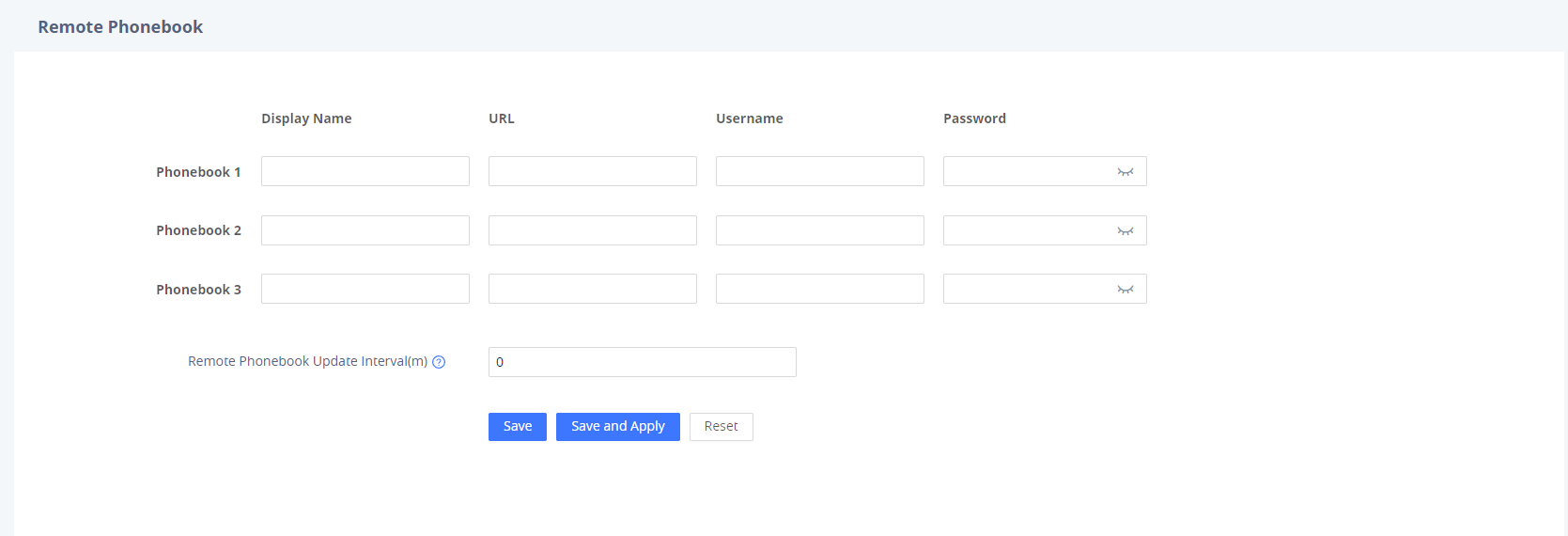
Remote Phonebook The user can configure up to 3 XML Remote Phonebooks. | |
Display Name | Configures the entry information to be shown on phone’s LCD. |
URL | Configures the XML Phonebook URL. |
Username | The user name for the phonebook. |
Password | The password for the phonebook. |
Remote Phonebook Update Interval | Configures the Remote Phonebook download Interval (in minutes). If set to 0, automatic download will be disabled. Valid range is 5 to 720. |
Applications/Remote Phonebook
Applications/Recording
| Call Recording | |
| File name | Displays the name of the recording file |
| Duration | Displays the duration of the phone call |
| Date | Displays the date the call was recorded on |
| Operation | Delete, Modify or download the recording file |
| Normal Recording | |
| File name | Displays the name of the recording file |
| Duration | Displays the duration of the phone call |
| Date | Displays the date the call was recorded on |
| Operation | Delete, Modify or download the recording file |
Value-added Service Page Definitions
Value-added Service/Value-added Service
| Value-added Service (0/25) | |
| Service Type | Users can set the service type to “Door System” to configure the door system options, or to “DTMF” to set DTMF content to send it during calls. |
| Door System Type | Set the door system type to “GDS” if the GDS door system is used, or set it to “Baudisch” if another door system brand is used. Note: Each GDS door system has 2 different access passwords to control 2 doors separately named as [Related Display Name1] & [Related Display Name2] below for door 1 and 2 respectively. |
| System Number | Specifies the door system number which is the SIP user ID configured on door system or its IP address, if the door system is using IP call. It enables to show open door button when caller number or IP address matches with this setting. e.g:”36311″ or “192.168.124.81”. Note: When set “Door System Type” to “Baudisch” a “configure” button will appear to allow user to configure groups of door system URL and User ID for 100 entries.
|
| Display Name | Configures the display name of the door system. When the call matches the configured system number, the name will be displayed on LCD. |
| Related Display Name1 | Configures the name that will be displayed on LCD for door 1 when the call matches the configured GDS door system number. |
| Access password | Determines the door system password which should match the one configured on the used door system settings. In case the GDS is set as ‘Door System type’ parameter, the password should match the one configured on the GDS to open door 1. |
| Related Display Name2 | Indicates the name that will be displayed on LCD for door 2 when the call matches the configured system number. |
| Access password | The configured password should match the one configured on the GDS to open door 2. |
| System Ringtone | Allows users to configure the ringtone for the door System. Users can choose different ringtones from the dropdown list. |
| DTMF Content | Set the DTMF content that is going to be sent when the DTMF button is pressed under Call screen🡪“Keypad”. |
| General Settings | |
| Display Open Door Button when Calling | Configures whether display Open Door button when there is an incoming call. If set to “Yes”, you cannot open door with DTMF when preview function is disabled, the phone will hide open door button automatically. |
| Enable Preview | Configures whether to enable preview function or not. If set to “No”, you cannot open door with DTMF when there is an incoming call, the phone will hide open door button automatically. |
UPGRADING AND PROVISIONING
The GXV34x0 phones can be upgraded via TFTP/HTTP/HTTPS by configuring the URL/IP Address for the TFTP/HTTP/HTTPS server and selecting a download method. Configure a valid URL for TFTP, HTTP or HTTPS; the server name can be FQDN or IP address.
Examples of valid URLs:
firrmware.grandstream.com
Upgrade and Provisioning Configuration
There are two ways to setup upgrade and provisioning on GXV34x0 phones. They are Keypad Menu and Web GUI.
- Configure via keypad Menu
In GXV34x0 Settings, select Advanced 🡪 System Updates.- Press Detect New Version to check for new firmware versions if available.
- Press on Start provision to trigger the provision process
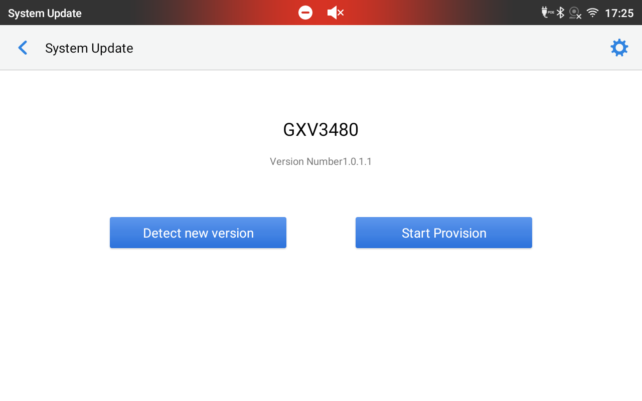
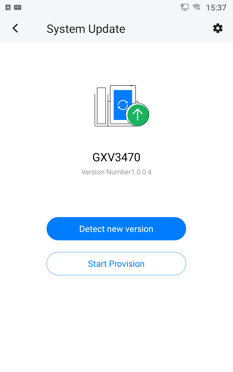
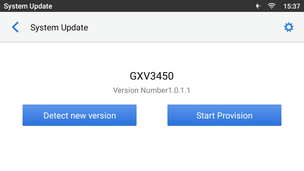
3. Press settings icon ![]() to configure upgrade settings. Users may then select the upgrade mode and enter the IP address or FQDN for the Firmware server and the Config server. After making the changes, tap Save button to save the change. Then reboot the phone or go back and press Detect New Version.
to configure upgrade settings. Users may then select the upgrade mode and enter the IP address or FQDN for the Firmware server and the Config server. After making the changes, tap Save button to save the change. Then reboot the phone or go back and press Detect New Version.
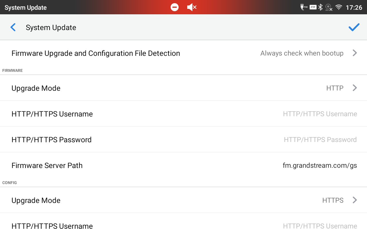
- Configure via Web GUI
Open a web browser on PC and enter the IP address for the GXV34x0 phone. Then login with the administrator username and password (that needs to be at least 6 characters). Go to Maintenance 🡪 Upgrade. In the Upgrade web page, enter the IP address or the FQDN for the upgrade server and choose to upgrade via TFTP, HTTP or HTTPS (The default setting is HTTPS). Save and apply the changes, press Upgrade button or reboot the phone to initiate firmware upgrade process.
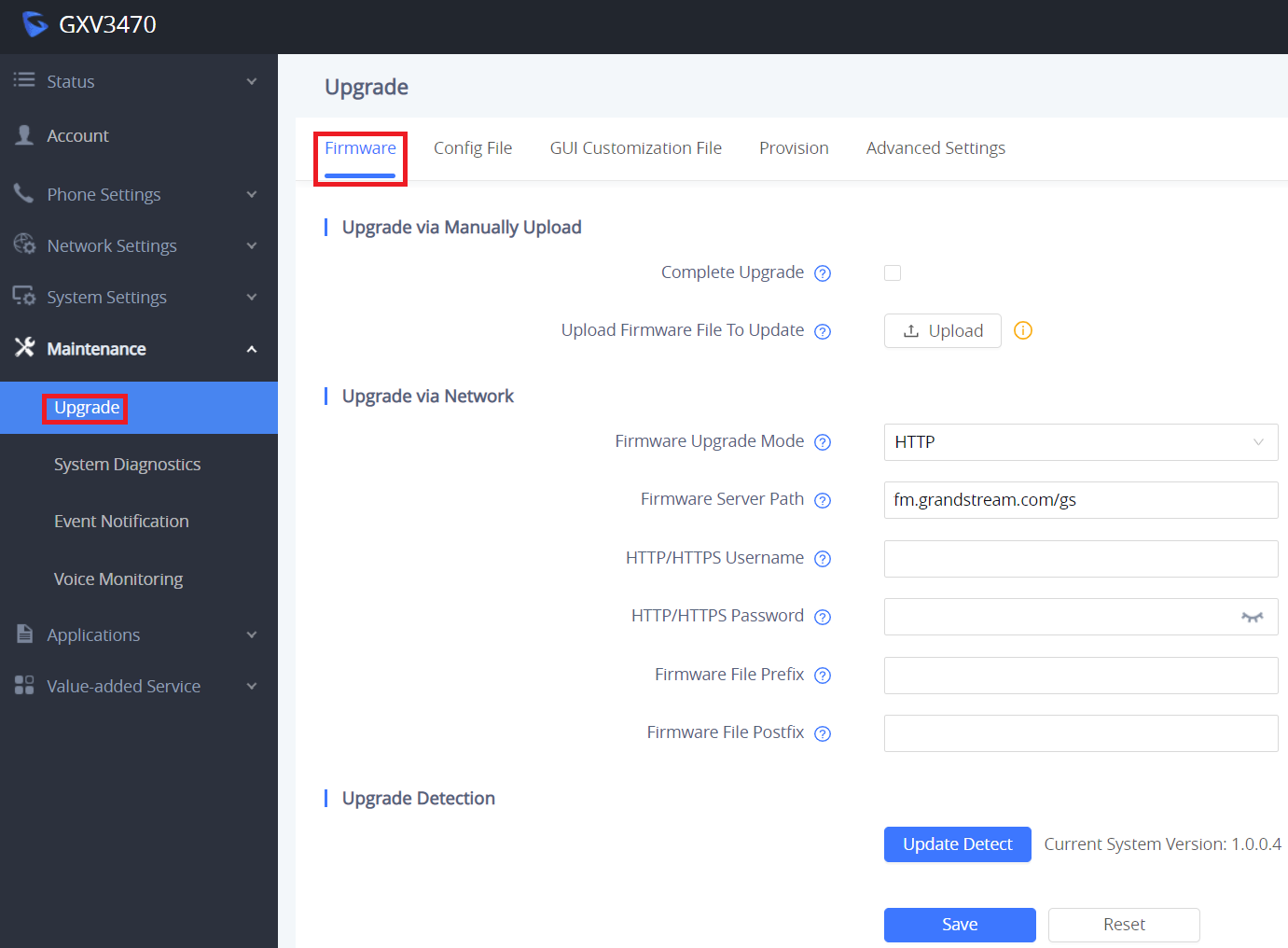
Upload Firmware Locally
If there is no HTTP/TFTP server, users could also upload the firmware to the GXV34x0 directly via Web GUI. Please follow the steps below to upload firmware to GXV34x0 locally.
- Download the latest GXV34x0 firmware file from the following link and save it in your PC.
https://www.grandstream.com/support/firmware
2. Log in the Web GUI as administrator in the PC.
3. Go to Web GUI🡪Maintenance🡪Upgrade.
4. Click the “Upload” button, a window will be prompted to select firmware file to upload.
5. Select the firmware file from your PC. Then uploading progress will show at the button where it was “Upload” in the above step.
6 . When uploading is done, users can see the upgrading process starts on the GXV34x0 LCD.
7. The phone will reboot again with the new firmware version upgraded.

Upgrade via USB flash drive
For users that could not use remote upgrade or could not access the phone’s Web GUI to upload firmware, upgrading via USB flash drive is an alternative. Follow the steps below to upgrade GXV34x0 USB flash drive.
Step 1: Plug in USB flash drive into your PC USB (Type-A) port. Download the firmware file to PC and save it in the root directory of USB flash drive.
Note:
- You can copy firmware to different USB flash drives. Multiple GXV340 upgrades can be performed simultaneously.
- Please make sure the firmware filename is gxv3480fw.bin, gxv3470fw.bin or gxv3450fw.bin.
Step 2: Remove the USB flash drive from the PC and insert it to GXV34X0 USB (Type-A) Port.
Step 3: Wait for a moment, GXV34X0 will automatically detects the current version and the new version. Following pop-up window will displayed on LCD screen.
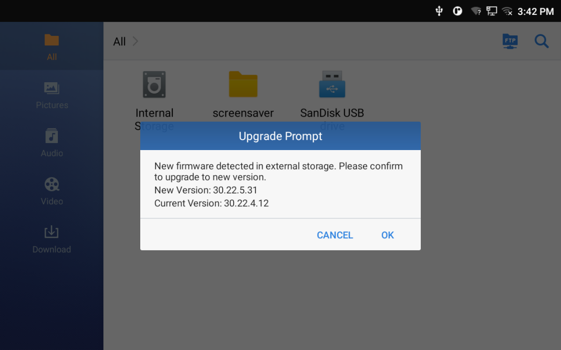
Step 4: Click “OK” , the device will perform upgrade automatically. This process will takes about 3 minutes.
Note: When prompted by this screen, ensure that the USB flash drive is inserted into the device.
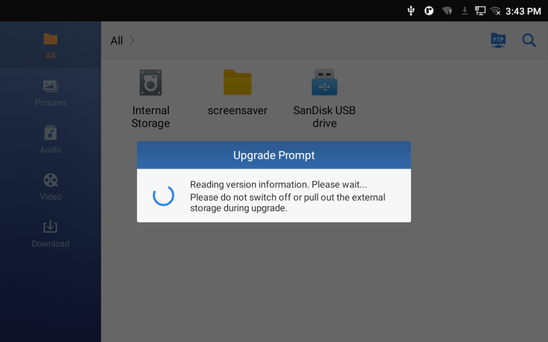
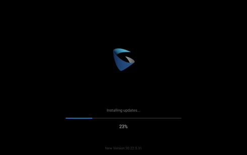
Step 5: Wait until the upgrading is done. The GXV34X0 will reboot itself. Go to Settings ->Status->System Info to check the firmware current version.
No Local Firmware Servers
Service providers should maintain their own firmware upgrade servers. For users who do not have a TFTP/HTTP/HTTPS server, some free Windows version TFTP servers are available for download from:
https://www.solarwinds.com/free-tools/free-tftp-server and http://tftpd32.jounin.net/.
Please check our web site at https://www.grandstream.com/support/firmware for latest firmware.
Instructions for local firmware upgrade via TFTP:
- Unzip the firmware files and put all of them in the root directory of the TFTP server;
- Connect the PC running the TFTP server and the GXV34x0 device to the same LAN segment;
- Launch the TFTP server and go to the File menu🡪Configure🡪Security to change the TFTP server’s default setting from “Receive Only” to “Transmit Only” for the firmware upgrade;
- Start the TFTP server and configure the TFTP server in the phone’s web configuration interface;
- Configure the Firmware Server Path to the IP address of the PC;
- Update the changes and reboot the GXV34x0.
End users can also choose to download a free HTTP server from https://httpd.apache.org/ or use Microsoft IIS web server.
Provisioning and Configuration File Download
Grandstream SIP Devices can be configured via the Web Interface as well as via a Configuration File (binary or XML) through TFTP or HTTP/HTTPS. The “Config Server Path” is the TFTP, HTTP or HTTPS server path for the configuration file. It needs to be set to a valid URL, either in FQDN or IP address format. The “Config Server Path” can be the same or different from the “Firmware Server Path”.
A configuration parameter is associated with each particular field in the web configuration page. A parameter consists of a Capital letter P and 2 to 3 (Could be extended to 4 in the future) digit numeric numbers. i.e., P2 is associated with the “Admin Password” in the Web GUI🡪System Settings🡪Security Settings🡪User Info Management page. For a detailed parameter list, please refer to the corresponding firmware release configuration template in the following link:
https://www.grandstream.com/support/tools
When the GXV34x0 boots up, it will issue TFTP or HTTP request to download a configuration XML file named “cfgxxxxxxxxxxxx” followed by “cfgxxxxxxxxxxxx.xml”, where “xxxxxxxxxxxx” is the MAC address of the phone, i.e., “cfg000b820102ab” and “cfg000b820102ab.xml”. If downloading “cfgxxxxxxxxxxxx.xml” file is not successful, the provision program will download a model specific file “cfggxv34x0.xml” then a generic cfg.xml file. The configuration file name should be in lower case letters.
For more details on XML provisioning, please refer to the following document:
https://documentation.grandstream.com/knowledge-base/sip-device-provisioning-guide/
Note:
When the prompt in the figure below shows up, it means the firmware/config authentication failed. So the user will be required to check the username/password on device web UI 🡪 Maintenance 🡪Upgrade:
Firmware HTTP/HTTPS username
Firmware HTTP/HTTPS password
Config HTTP/HTTPS username
Config HTTP/HTTPS password
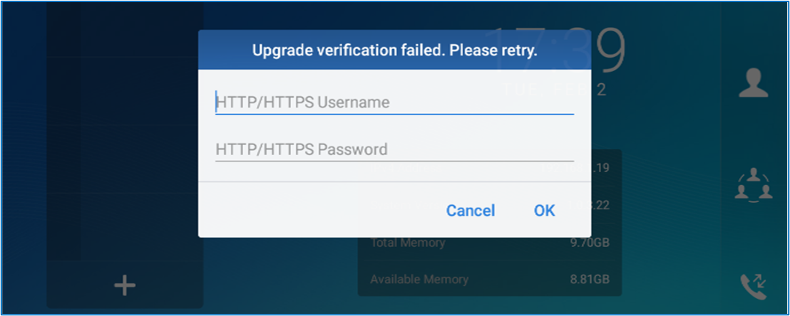
FACTORY RESET
Restore to Factory Default via LCD Menu
In order to restore the GXV34x0 unit to factory reset via the LCD Menu, please, refer to the following steps:
- On GXV34x0 idle screen, go to Settings 🡪 Advanced 🡪 System Security 🡪 Factory reset.
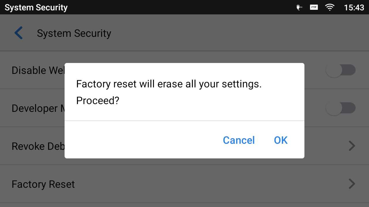
2. Tap on OK to confirm.
Restore to Factory Default via the Web GUI
- Login GXV34x0 Web GUI and go to Maintenance 🡪 Upgrade 🡪 Advanced Settings.
- At the bottom of the page, click on the Reset button for Factory reset.

3. A dialog box will pop up to confirm factory reset;
4. Click OK to restore the phone to factory settings.
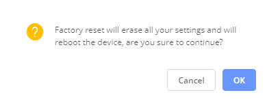
Restore to Factory Default via Hard Keys
For users that could not restore the GXV34x0 to factory reset via LCD Menu or the Web GUI, restoring the unit via Hard keys is an alternative. Please, follow the steps below to restore the GXV34x0 via Hard Keys:
- Power cycle the GXV34x0.
- Press and hold the numeric keypad 1+9 for more than 10s (GXV3450 support) or press and hold the reset pin hole for more than 10s (GXV3470 & GXV3480 support).
- The LCD screen will display “Factory reset, please wait”.
- The GXV34x0 will reboot with factory default settings.
SAFE MODE
Users can enter safe mode by pressing the Menu button ![]() during bootup. Before entering the safe mode, please power cycle the phone and when the plain text “GRANDSTREAM” shows up, immediately press and hold the Menu button
during bootup. Before entering the safe mode, please power cycle the phone and when the plain text “GRANDSTREAM” shows up, immediately press and hold the Menu button ![]() when the five buttons light up again after the top right LED flash ends. Users will see the phone boot up in safe mode.
when the five buttons light up again after the top right LED flash ends. Users will see the phone boot up in safe mode.
Under safe mode, only the system applications will be up and running. Normally safe mode is not needed unless the phone cannot function anymore caused by incompatible 3rd party applications. For example, if a 3rd party application is downloaded and installed on the phone that cause the phone keep crashing or freezing and users cannot operate on the phone’s settings, users can enter safe mode to remove the 3rd party application and boot up in normal mode again.
Screen Sharing
Screen Sharing is a feature available on the GXV34xx video phones series.
This feature allows the user to cast the presentation from a PC to destination display output.
After logging in the web UI as administrator:
- Click on the web UI -> Share Screen on the top right corner
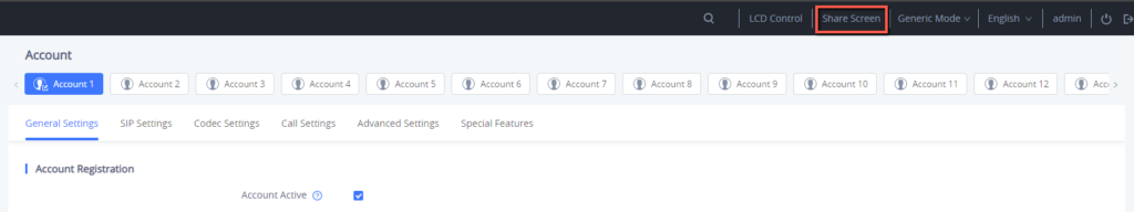
2. Select an interface from the tabs. Then the other side would display the PC interface in the video call.
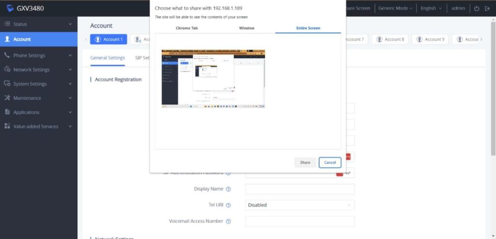
LCD Control
The LCD control feature is added to the GXV34xx video phone series starting from firmware 1.0.3.4, it allow the users to remotely access the LCD inteface of the GXV34xx video phone and modify its parameters as if it is being modified from the LCD screen directly.
To enable the LCD contro from web ui:
- Enter the GXV34xx IP address on a browser.
- Once connected to the web ui interface select the LCD Control option on the top right corner:
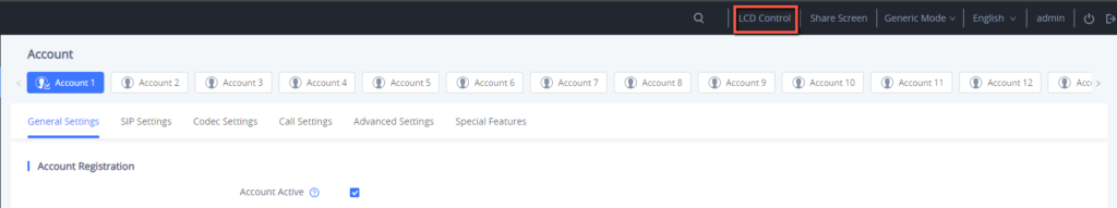
3. Once selected you will automatically be prompted with a pop up that displays a screen cast of the GXV34xx LCD screen, where you can modify the parameters of the device, in the same way you would on the actual device.
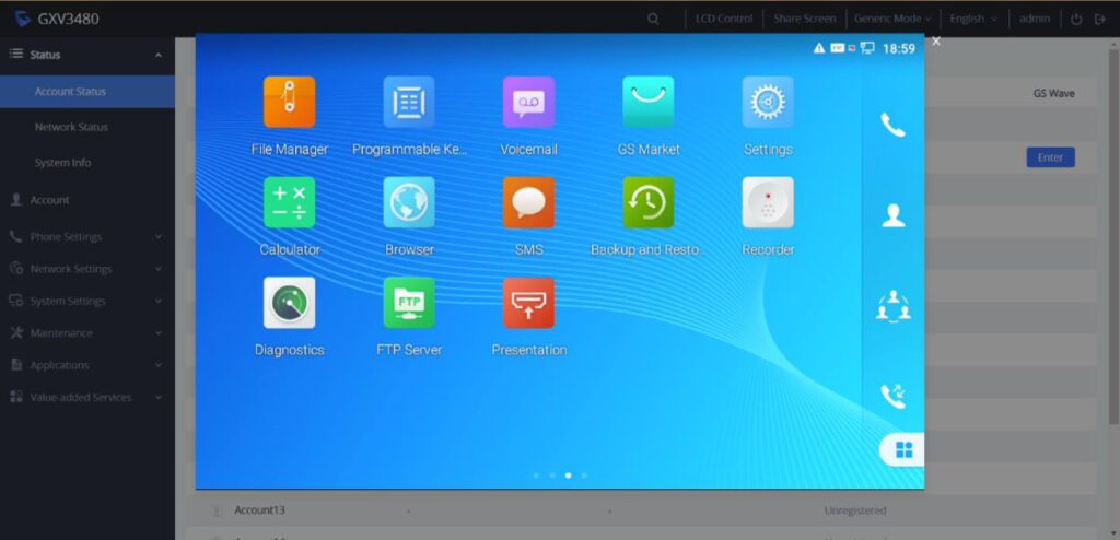
ZOOM MODE
Zoom Mode is added to the web UI to fully integrate the device with the Zoom app. Zoom Mode can be accessed from the web UI’s top right corner, as shown below. The Zoom app will be launched automatically by the device. When enabled, the phone only runs the Zoom app.
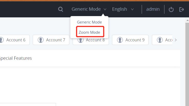
After enabling the zoom mode, Only The following Tabs will be available for preview or configuration:
- Status
- Network Status
- System info
- Network Settings
- Ethernet Settings
- Wi-Fi Settings
- OpenVPN Settings
- Advanced Network Settings
- SNMP Settings
- System Settings
- Time and Language
- Security Settings
- Preferences
- TR069
- Maintenance
- Upgrade
- System Diagnostics
ONE-CLICK CONFIGURATION
“One Click Configuration” is a specialized application designed to simplify the Process of SIP registration of the GXV Phones on the same network as the GCC601X.
Its primary function is to help provision an account from the PBX module of the GCC601x to a designated GXV device within the same network as the GCC.
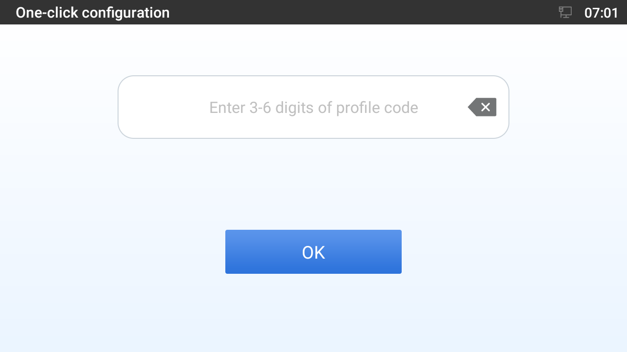
How it works
- When your GXV34xx device boots up on the same network as GCC601X, the app is ready to help provision an account from the GCC device.
- Create the extension that you want to provision to the GXV device under the UC Endpoints module of the GCC601X, once created, an automatic 6-digits ID code will be generated for the specific extension, you can also manually provide a pin for the extension between 3-6 digits.
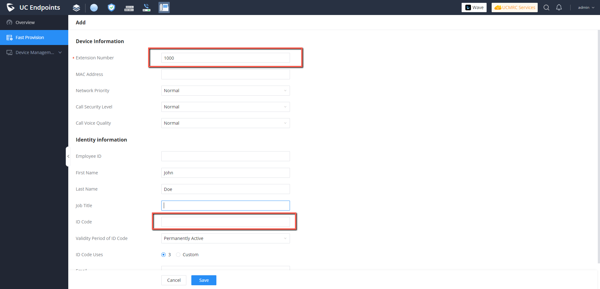
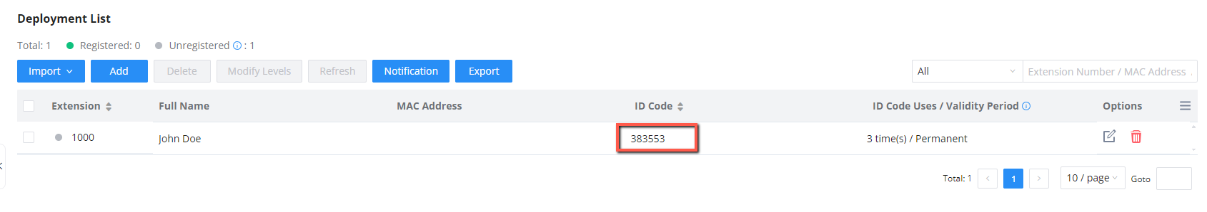
- Open the One-click configuration app, then simply input the unique ID code provided by GCC601X under the Fast Provision section of the UC Endpoints module of the GCC device.
- The app verifies the entered profile code to ensure it’s correct and authentic.
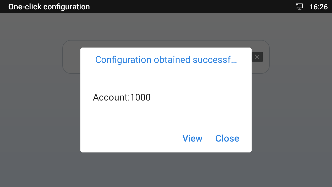
- Once the code is validated, the GCC610x/W automatically provisions the assigned account to your GXV device.
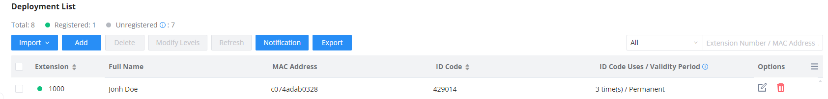
- To prevent unauthorized access attempts, the app temporarily suspends provisioning for a brief period (typically 15 minutes) if the profile code is incorrectly entered multiple times.
“One-Click Configuration” simplifies the setup process for GXV34xx devices by automating the provisioning of assigned accounts based on a unique profile code, while also implementing security measures to safeguard against unauthorized access attempts.
EXPERIENCING THE GXV34x0 APPLICATION PHONE
Please visit our website: https://www.grandstream.com to receive the most up- to-date updates on firmware releases, additional features, FAQs, documentation and news on new products.
We encourage you to browse our product related documentation, FAQs and User and Developer Forum for answers to your general questions. If you have purchased our products through a Grandstream Certified Partner or Reseller, please contact them directly for immediate support.
Our technical support staff is trained and ready to answer all of your questions. Contact a technical support member or submit a trouble ticket online to receive in-depth support.
Thank you again for purchasing Grandstream Enterprise Application phone, it will be sure to bring convenience and color to both your business and personal life.
* Android is a trademark of Google LLC.
* Zoom is Registered Trademarks of Zoom Video Communications, Inc.
© 2002-2014 OpenVPN Technologies, Inc.
OpenVPN is a registered trademark of OpenVPN Technologies, Inc.

HDMI, the HDMI Logo, and High-Definition Multimedia Interface are trademarks or registered trademarks of HDMI Licensing LLC in the United States and other countries.
COPYRIGHT
©2021 Grandstream Networks, Inc. https://www.grandstream.com
All rights reserved. Information in this document is subject to change without notice. Reproduction or transmittal of the entire or any part, in any form or by any means, electronic or print, for any purpose without the express written permission of Grandstream Networks, Inc. is not permitted.
The latest electronic version of this guide is available for download here:
https://www.grandstream.com/support
Grandstream is a registered trademark and Grandstream logo is trademark of Grandstream Networks, Inc. in the United States, Europe and other countries.
CAUTION
Changes or modifications to this product not expressly approved by Grandstream, or operation of this product in any way other than as detailed by this guide, could void your manufacturer warranty.
WARNING
Please do not use a different power adaptor with devices as it may cause damage to the products and void the manufacturer warranty.
FCC Statement
This equipment has been tested and found to comply with the limits for a Class B digital device, pursuant to part 15 of the FCC Rules. These limits are designed to provide reasonable protection against harmful interference in a residential installation. This equipment generates, uses and can radiate radio frequency energy and, if not installed and used in accordance with the instructions, may cause harmful interference to radio communications. However, there is no guarantee that interference will not occur in a particular installation.
If this equipment does cause harmful interference to radio or television reception, which can be determined by turning the equipment off and on, the user is encouraged to try to correct the interference by one or more of the following measures:
- Reorient or relocate the receiving antenna.
- Increase the separation between the equipment and receiver.
- Connect the equipment into an outlet on a circuit different from that to which the receiver is connected.
- Consult the dealer or an experienced radio/TV technician for help.
The device complies with FCC radiation exposure limits set forth an uncontrolled environment and it also complies with Part 15 of the FCC RF Rules. This equipment must be installed and operated in accordance with provided instructions and the antenna(s) used for this transmitter must be installed to provide a separation distance of at least 20 cm from all persons and must not be co-located or operating in conjunction with any other antenna or transmitter. End-users and installers must be provided with antenna installation instructions and consider removing the no-collocation statement.
This device complies with Part 15 of the FCC Rules. Operation is subject to the following two conditions: (1) this device may not cause harmful interference, and (2) this device must accept any interference received, including interference that may cause undesired operation.
Caution
Any changes or modification not expressly approved by the party responsible for compliance could void the user’s authority to operate the equipment.
CE DECLARATION OF CONFORMITY
This transmitter complies with the essential requirements and provisions of directives 2014/53/EU, 2014/30/EU, 2015/35/EU and subsequent amendments, according to standards
Draft ETSI EN 301 489-1 V2.2.1;Draft ETSI EN 301 489-17 V3.2.0;
EN 55032:2015 /AC:2016;EN55035:2017;EN61000-3-3:2013;EN 61000-3-2:2014
ETSI EN 300 328 V2.1.1;ETSI EN 301 893 V2.1.1;EN 62311: 2008;EN 62368-1:2014
Manufacturer: Grandstream Networks, Inc.126 Brookline Ave, 3rd Floor Boston, MA 02215, USA
Caution: Exposure to Radio Frequency Radiation
This equipment complies with EU radiation exposure limits set forth for an uncontrolled environment. This equipment should be installed and operated with minimum distance of 20 cm between the radiator and your body.
CE Authentication
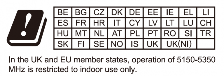

For Certification, Warranty and RMA information,
please visit www.grandstream.com
Hereby, Grandstream Networks, Inc. declares that the radio equipment GXV34x0 is in compliance with Directive 2014/53/EU.
The full text of the EU declaration of conformity is available at the following internet address:
https://www.grandstream.com/support/resources/
RF Power and Power Adapter Statement
| WLAN | ||
| Standard | Frequency | EIRP Power (dBm) |
| Wi-Fi 2.4G | 2.4~2.4835GHZ | 18.70 |
| Wi-Fi 5G | 5.15~5.25GHz | 22.06 |
| 5.25~5.35GHz | 19.21 | |
| 5.47~5.725GHz | 18.24 | |
| Bluetooth | ||
| Bluetooth version | EIRP Power (dBm) | |
| EDR | 12.14 | |
| LE | 8.42 |
The power adapter is a power-off device.
GNU GPL INFORMATION
GXV34x0 firmware contains third-party software licensed under the GNU General Public License (GPL). Grandstream uses software under the specific terms of the GPL. Please see the GNU General Public License (GPL) for the exact terms and conditions of the license.
Grandstream GNU GPL related source code can be downloaded from Grandstream web site from:
https://blog.grandstream.com/faq/gnu-general-public-license/gnu-gpl-information-download
CHANGE LOG
This section documents significant changes from previous versions of administration guide for GXV34x0. Only major new features or major document updates are listed here. Minor updates for corrections or editing are not documented here.
Firmware Version 1.0.3.12
Product Name: GXV3480 / GXV3450 / GXV3470
- Added One-click Configuration app on LCD to integrate with GCC device. [ONE-CLICK CONFIGURATION APP]
- Supported displaying longer string on the Programmable Keys widget. [DISPLAY LONG STRING]
- Added option to retrieve user access. [Enable User Web Access]
Firmware Version 1.0.3.4
Product Name: GXV3480 / GXV3450 / GXV3470
- Added support for “Account Disaster Recovery” under web UI Phone Settings. [Account Disaster Recovery]
- Added support for remote access to the web UI via GDMS device options menu. [Upgrade/Provisioning]
- Added support for Remote Phonebook on web UI. [Remote Phonebook]
- Added support for Enterprise Directories on web UI. [Enterprise Directories]
- Added support for web screen sharing. [Screen Sharing]
- Added LCD Control on web UI. [LCD Control]
- Added support to enable/disable screenshot control. [Enable Screenshot]
- Added support for VP8 video codec in web UI account codec settings. [Preferred Video Codec]
- Applications/ContactsAdded support for G.722.1 and G.722.1C audio codecs in web UI account codec settings. [Preferred Audio Codec]
- Added support for Dynamic lock. [Dynamic Lock]
- Added support for Virtual Background. [Virtual Background]
- Supported Schedule Tasks from web UI. [Scheduled Tasks]
- Increase contact maximum volume to 2000 inputs. [Contacts]
Firmware Version 1.0.1.33
Product Name: GXV3480 / GXV3450 / GXV3470
- Supported up to 25 value-added services. [Value-added Service]
- Supported sorting LDAP result by number from web UI. [LDAP SORTING]
- Removed the default STUN server from web UI. [STUN Server]
Firmware Version 1.0.1.29
Product Name: GXV3480 / GXV3450 / GXV3470
- Added option to enable/disable local camera. [ENABLE/DISABLE LOCAL CAMERA]
Firmware Version 1.0.1.21
Product Name: GXV3480 / GXV3450 / GXV3470
- Added Support for Zoom Mode. [Zoom mode]
Firmware Version 1.0.1.16
Product Name: GXV3480 / GXV3450
- Updated settings layout in web UI account settings.
Product Name: GXV3470
- Updated settings layout in web UI account settings.
- Added Save & Apply button for account settings.[Account settings]
Firmware Version 1.0.1.1
Product Name: GXV3480 / GXV3450
- This is the Initial Version.
Firmware Version 1.0.0.4
Product Name: GXV3470
- This is the Initial Version.