
Thank you for purchasing the Grandstream GXW450X Digital VoIP Gateway. The GXW450X offers an easy-to-manage, easy-to-configure IP communications solution for any business with virtual and/or branch locations. The GXW450X supports popular voice codecs and is designed for full SIP compatibility and interoperability with third-party SIP providers, thus enabling you to fully leverage the benefits of VoIP technology, integrate an ISDN system into a VoIP network, and efficiently manage GXW450x supports SNMP (Simple Network Management Protocol) which is widely used in network management for network monitoring for collecting information about monitored devices.
This manual will help you learn how to operate and manage your GXW450X Digital Gateway and make the best use of its many upgraded features including simple and quick installation, multi-party conferencing, and direct IP-IP Calling. This Digital VoIP Gateway is very easy to manage and scalable, specifically designed to be an easy-to-use and affordable VoIP solution for large and medium-sized enterprises
GATEWAY GXW450X OVERVIEW
The GXW450X series are E1/T1/J1 Digital VoIP Gateways that allow digital PSTN and ISDN trunks to be integrated with VoIP networks. By connecting the GXW450X series with a VoIP network and traditional PBX or E1/T1/J1 providers, businesses can drastically increase the number of PSTN/ISDN trunks integrated with their VoIP network and the concurrent calls supported. The GXW450X series offers three models that provide 1, 2, or 4 T1/E1/J1 spans and support 30, 60, or 120 concurrent calls.
Feature Highlights
The following table contains the major features of the GXW450X:
 GXW450X |
|
GXW450X Features Highlights
GXW450X Technical Specifications
The following table resumes all the technical specifications including the protocols/standards supported, voice codecs, languages, and upgrade/provisioning settings for the GXW450X
Interfaces | |
T1/E1/J1 Interface | 1/2/4 RJ45 ports, supporting up to 30/60/120 simultaneous VoIP calls |
Network Interfaces | Dual self-adaptive Gigabit ports (switched or routed) |
Peripheral Ports | (2) USB 3.0, (1) SD card interface |
LED Indicators | WAN, LAN, T1/E1/J1 |
LCD Display | 128×32 dot matrix graphic LCD with DOWN and OK buttons |
Reset Switch | Yes, long press for factory reset and short press for the reboot. |
Voice Capabilities | |
Voice-over-Packet Capabilities | LEC with NLP Packetized Voice Protocol Unit, 128ms-tail-length carrier grade Line Echo Cancellation, Dynamic Jitter Buffer, Modem detection & auto-switch to G.711 |
Voice and Fax Codecs | G.711 A-law/U-law, G.722, G.723.1 5.3K/6.3K, G.726, G.729A/B, Opus, iLBC, GSM-FR, AAL2-G.726-32 |
Fax over IP | T.38 compliant Group 3 Fax Relay up to 14.4kpbs and auto-switch to G.711 for Fax Passthrough, Fax data pump V.17, V.21, V.27ter, V.29 for T.38 fax relay. |
Voice-quality Enhancement | Echo cancellation (G.168-2004), Jitter buffer, Silence suppression (VAD, CNG), PLC |
QoS | Layer 2 QoS (802.1Q, 802.1p) and Layer 3 (ToS, DiffServ, MPLS) QoS |
Signaling & Control | |
DTMF Methods | In-band audio, RFC2833, and/or SIP INFO |
Digital Signaling | SIP (RFC 3261) over UDP/TCP/TLS, PRI, SS7, MFC R2, RBS (pending)
PRI switch types: Euro ISDN, nation, Q.SIG
CAS: MFC R2 (Argentina, Brazil, China, Czech Republic, Colombia, Ecuador, Indonesia, ITU, Mexico, Philippines, Venezuela)
SS7: ITU, ANSI, China |
Upgrade | Firmware upgrade via TFTP / HTTP / HTTPS or local HTTP upload |
Device Management | Syslog, HTTPS, Web browser, voice prompt, backup and restore, port capture, and packet capture |
Network Protocols | TCP/UDP/IP, RTP/RTCP, ICMP, ARP, DNS, DDNS, DHCP, NTP, TFTP, SSH, HTTP/HTTPS, PPPoE, STUN, SRTP, TLS, LDAP, PPP, Frame Relay (pending), IPV6, OpenVPN® |
Status and statistic | Call status and history, device status monitoring, and ISDN status monitoring |
Security | |
Media Encryption | SRTP, TLS, HTTPS, SSH, 802.1X |
User-defined ports | SIP port, RTP port, HTTP/HTTPS port |
Advanced Defense | Fail2ban, alert events, Whitelist, Blacklist, strong password-based access control |
Physical | |
Universal Power Supply | Input: 100-240VAC, 50/60Hz Output: DC+12V/2A |
Physical & Dimensions | GXW4501: Unit Weight: 2350g; Package Weight: 3130g
GXW4502: Unit Weight: 2360g; Package Weight: 3140g GXW4504: Unit Weight: 2380g; Package Weight: 3160g Unit Dimensions: 485mm(L) x 191mm(W) x 46.2mm (H) |
Temperature and Humidity | Operating: 32 – 113ºF / 0 ~ 45ºC, Humidity 10 – 90% (non-condensing) Storage: 14 – 140ºF / -10 ~ 60ºC, Humidity 10 – 90% (non-condensing) |
Mounting | Rack mount & Desktop |
Additional Features | |
Multi-Language Support | Web UI: English, Simplified Chinese, Traditional Chinese, Spanish, French, Portuguese, German, Russian, Italian, Polish, Czech; Customizable IVR/voice prompts: English, Chinese, British English, German, Spanish, Greek, French, Italian, Dutch, Polish, Portuguese, Russian, Swedish, Turkish, Hebrew, Arabic; Customizable language pack to support any other languages |
Compliance | FCC: 47 C.F.R FCC Part 15 Class B; 47 C.F.R FCC Part 68 (TIA-968-B Section 5.2.4 (T1+ISDN))
CE : EN 55032,EN 55035,EN 61000-3-2,EN 61000-3-3,EN 60950-1,TBR 4 (E1+ISDN),TBR 12 (E1),TBR 13 (E1+ISDN)
RCM: AS/NZS CISPR 32,AS/NZS 61000.3.2,AS/NZS 61000.3.3,AS/NZS 60950.1,AS/ACIF S016(E1),AS/ACIF S038(E1+ISDN)
Other: ITU K.21 (Enhanced Levels); UL 60950-1 (Power adapter) |
GXW450X Technical Specifications
GETTING STARTED
This chapter provides basic installation instructions including the list of the packaging contents and also information for obtaining the best performance with the GXW450X.
Equipment Packaging
Unpack and check all accessories. Equipment includes

Connecting the GXW450X
Connecting the GXW450X gateway is easy. Follow these steps to connect your GXW450X gateway to the Internet and access the unit’s configuration pages.
- Connect one end of a straight-through RJ45 Ethernet cable into the WAN port of the GXW450X; connect the other end to the uplink port of an Ethernet switch/hub.
- Connect the 12V DC power adapter to the DC 12V power jack on the back of the GXW450X. Insert the main plug of the power adapter into a surge-protected power outlet.
- Connect one end of the T1/E1/J1 cable provided by the service provider into the T1/E1/J1 port of the GXW450X; connect the other end to the T1/E1/J1 wall jack.
- Wait for the GXW450X to boot up. The front LCD display will show the GXW450X hardware information when the boot process is completed.
- Once the GXW450X is successfully connected to the network via the WAN port, the Network LED indicator will be lit green, and an IP address will be shown on the LCD display.
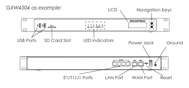
WAN/LAN ports | Ethernet ports used to connect the GXW to the local and external network |
RESET | Factory Reset button. Press and hold for a while to reset the factory default settings. |
Power Jack | Power adapter connection |
E1/T1/J1 ports | Digital port to be connected to a digital line. |
USB port | 2 Ports used to connect external USB drives to the GXW |
SD Card Slot | Reads the SD cards memory |
Ground | The ground screw needs to be connected to the ground. |
Diagram of GXW4504 Back and Front Panel
Using GXW450X Keypad Menu
The keypad menu of the GXW450X consists of 2 buttons: OK and Down keys to navigate different options.
- Press the “OK” key to start browsing menu options.
- Press “Down” to browse different menu options. Press “OK” to select an entry.
- In the menu option, select “Back” to go back to the previous menu.
- The LCD will return to default display after being idle in the menu for longer than 20 seconds.
The following table shows the LCD menu options.
View Events | Critical Events Other Events |
Device Info | Hardware: Hardware version number Software: Software version number P/N: Part number MAC: Device MAC address Uptime: System up time since the last reboot
|
Network Info | LAN Mode: DHCP, Static IP or PPPoE LAN IP: IP address LAN Subnet Mask
|
Network Menu | LAN Mode: Select LAN mode as DHCP, Static IP or PPPoE Static Routes Reset: Click to reset the static route setting
|
Factory Menu | Reboot Factory Reset LCD Test Patterns
Press “OK” to start. Then press the “Down” button to test different LCD patterns. When done, press the “OK” button to exit.
Fan Mode
Select “Auto” or “On”.
LED Test Patterns
Select “All On” “All Off” or “Blinking” and check the LED status for USB, SD, T1/E1/J1, Phone 1/Phone 2, Line 1/Line 2 ports. After the LED test, select “Back” in the menu, and the device will show the LED actual status again.
RTC Test Patterns
Select “2022-02-22 22:22” or “2011-01-11 11:11” to start the RTC (Real-Time Clock) test pattern. Check the system time from LCD idle screen by pressing the “DOWN” button, or from the Web GUI🡪System Status🡪General page. After the test, reboot the device manually and the device will display the correct time.
Hardware Testing
Select “Test DSP” to perform the DSP test on the device. This is mainly for factory testing purposes which verifies the hardware connection inside the device. The diagnostic result will display on the LCD after the test is done. |
Default Password | Showing the default Web login password. Once the password was changed, this menu will not show again. |
Web Info | Protocol: Web access protocol. HTTP or HTTPS. By default, it’s HTTPS Port: Web access port number. By default, it’s 8089
|
SSH Switch | Enable SSH: Enable SSH access. Disable SSH: Disable SSH access.
By default, SSH access is disabled. |
LCD Menu Options
Use the LED Indicators
The GXW450X has LED indicators in the front to display the connection status. The following table shows the status definitions.
LED Indicator | LED Status |
Power LAN WAN |
|
T1/E1/J1 |
|
GXW450X LED Indicators
Configuring GXW450X via Web GUI
Web GUI Access
The GXW450X embedded Web server responds to HTTP/HTTPS GET/POST requests. Embedded HTML pages allow users to configure the device through a Web browser such as Microsoft IE, Mozilla Firefox, or Google Chrome.

To access the Web GUI:
- Connect the computer to the same network as the GXW450X.
- Ensure the GXW450X is properly powered on and displays the IP address on the LCD screen.
- Open a web browser on the computer and enter the displayed IP address into the search bar in the following format: https://ipaddress:portnumber
- Enter username and password to login. (The default administrator username is “admin” and the default random password can be found on the sticker on the GXW450X).
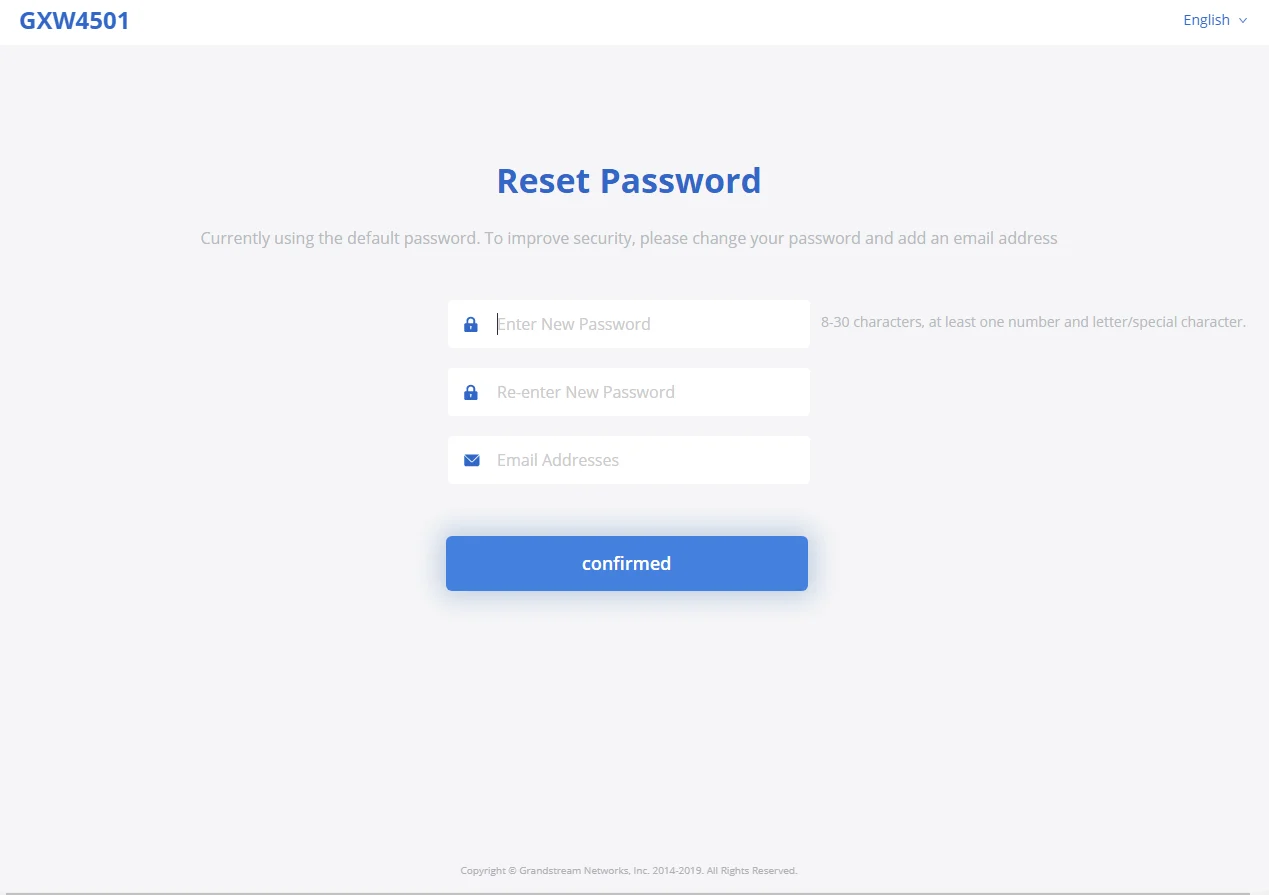
Reset Password at First Login
At first login, users will be forced to change the default admin password. The following screen will be shown, enter the requested information to proceed:
- Enter New Password
- Re-enter New Password
- Email Addresses: Email to be used to recover the password if lost.
Press “Confirmed” to apply the settings and access the web GUI.
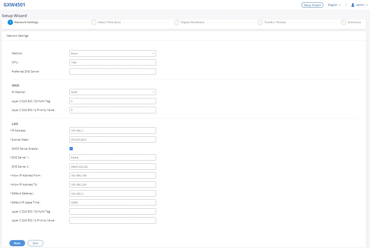
Setup Wizard
When the user logs in to the GXW450X Web GUI for the first time, he will be asked to change the default password and add an email address to improve security, and a setup wizard will provide guidance to set up basic configuration. Configurations in the setup wizard include Network settings, Time zone, and Trunk/routes.
Web GUI Configurations
There are six main sections in the Web GUI for users to view the Gateway status and configure and manage the GXW450X.
- System Status: Displays GXW450X Dashboard, System Information, Active calls, and network status.
- Trunk: To Digital and VoIP trunks and manage inbound/outbound call routes.
- Gateway Settings: SIP Settings, RTP Settings, and interface settings.
- System Settings: To configure The HTTP server, network settings, OpenVPN®, security settings, Email Settings, and Time Settings.
- Maintenance: To perform the firmware upgrade, backup configurations, user management cleaner setup, reset/reboot, Syslog setup, and troubleshooting
- CDR: View call records and download CDR reports.
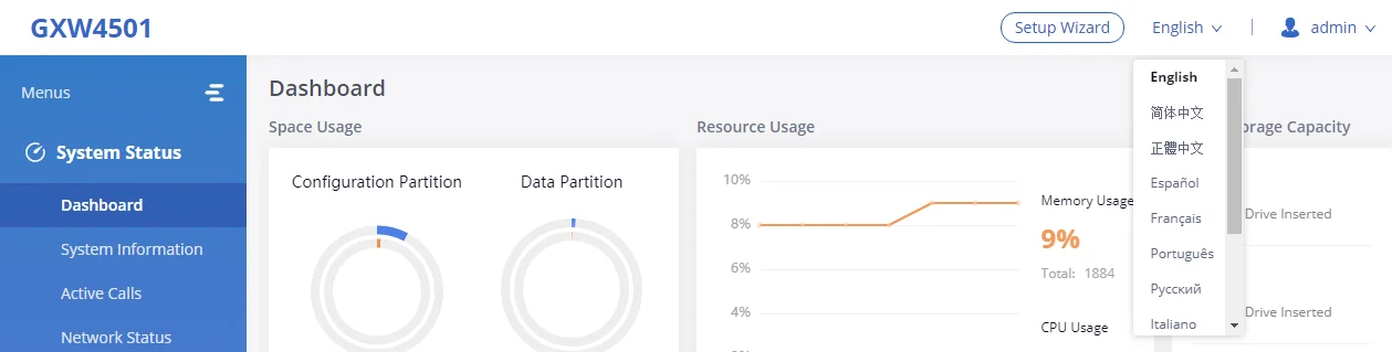
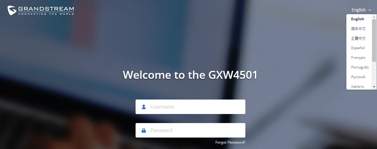
Web GUI Languages
Currently the GXW450X series Web GUI supports English, Simplified Chinese, Traditional Chinese,
Spanish, French, Portuguese, Russian, Italian, Polish, German, etc.
Users can select the displayed language on the Web GUI login page or at the upper right tab of the Web GUI after logging in.
Save and Apply Changes
Click on the “Save” button after configuring the Web GUI options on one page. After saving all the changes, make sure to click on the “Apply Changes” button on the upper right of the web page to submit all the changes. If the change requires a reboot to take effect, a prompted message will pop up for you to reboot the device.
SYSTEM STATUS
The System Status section is the interface that allows users to check the general information about the GXW450X such as software and hardware information, space usage, resources usage, etc.
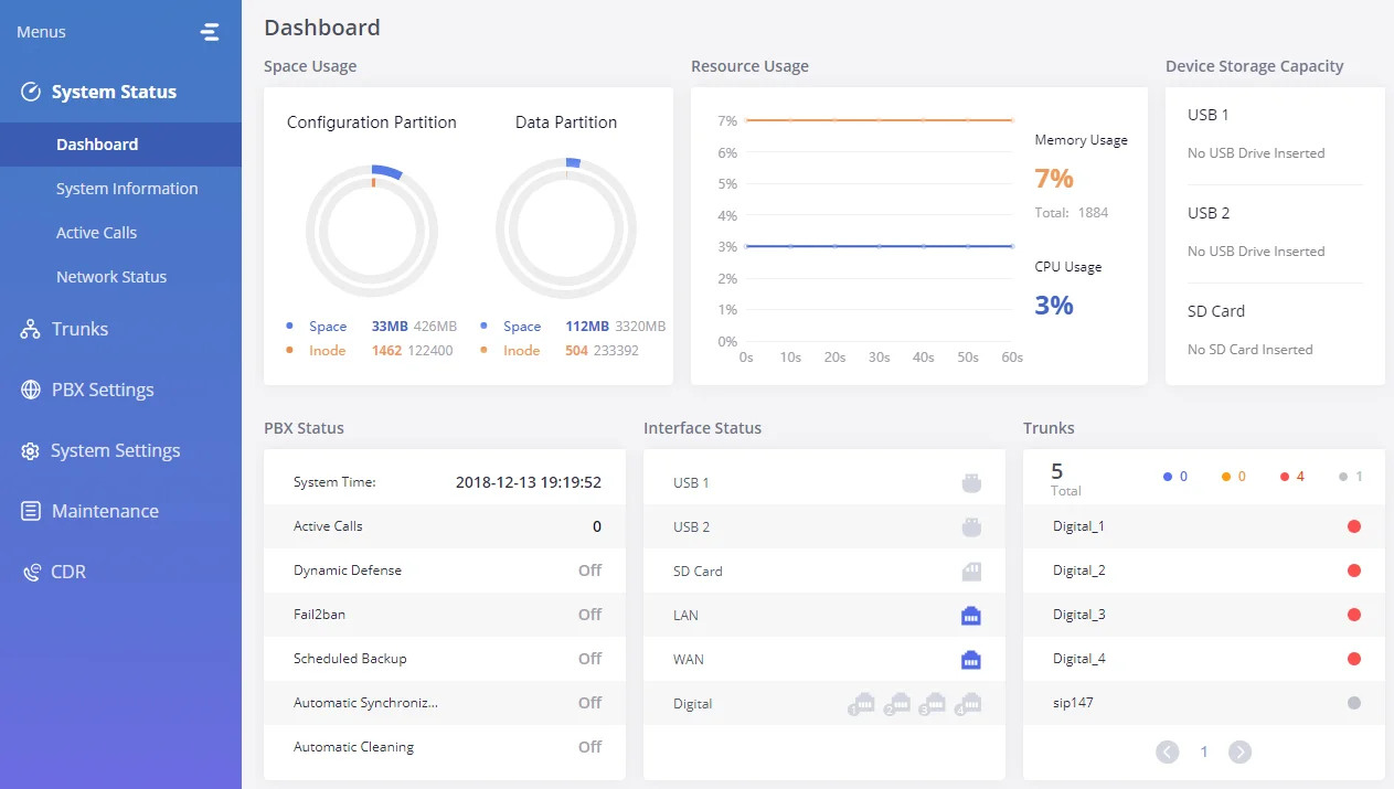
Dashboard
The GXW450X monitors the status of Trunks, Digital Channels, Disk capacities, etc. It presents administrators with the real-time status in different sections under the Web GUI🡪System Status🡪Dashboard.
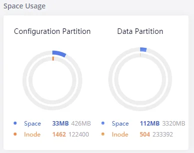
Space Usage
Users could access the space usage information from Web GUI🡪System Status🡪Dashboard 🡪Space Usage. It shows the available and used space for Space Usage and Inode Usage.
Space Usage includes:
- Configuration partition: This partition contains GXW450X system configuration files and service configuration files.
- Data partition: CDR records, Voice Prompts, etc.
Inode Usage includes:
- Configuration partition
- Data partition
Note: Inode is the pointer used for file reference in the system. The system usually has limited resources of pointers.
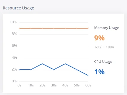
Resource Usage
When configuring and managing the GXW450X, users could access resource usage information to estimate the current usage and allocate the resources accordingly. Under Web GUI🡪System Status🡪Dashboard 🡪Resource Usage, the current CPU usage and Memory usage are shown in this chart.
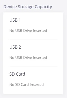
Disk Capacity
Users could check the external devices’ capacities from the Dashboard page of the GXW450X under Web GUI🡪System Status🡪Dashboard 🡪Device Storage Capacity.
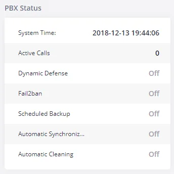
PBX Status
The PBX status shows the status of some of the gateway GXW450X services. Among the services monitored on the PBX status tab, there is System Time, Active Calls, Schedule backup, etc.
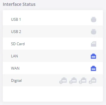
Interfaces Status
This section displays the interface connection status on the GXW450X for USB, SD Card, LAN, WAN, and Digital interfaces.
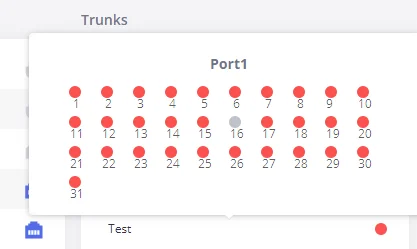
Trunks
Users could see all the configured trunks’ status in this section.
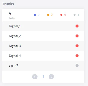
Four statuses are possible for any trunk configured on the GXW450X:
- Available
- Busy
- Abnormal
- Unmonitored
To visualize the state of each channel of the Digital trunk, users can waver the mouse over the status of the digital trunk as shown on the figure below:
System Information
The GXW450X system Information can be accessed via Web GUI🡪System Status🡪System Information, which displays the following system information.
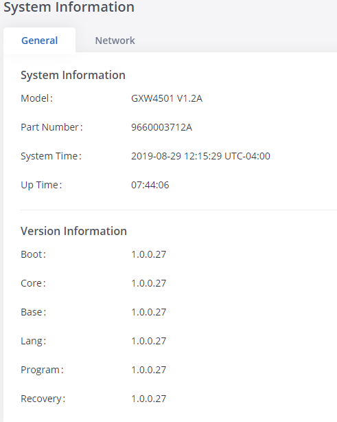
General
On this menu, users could check the hardware and software information for the GXW450X. Please see the details in the following table.
System Information | |
Model | Product model. |
Part Number | Product part number. |
System Time | Current system time. The current system time is also available on the upper right of each web page. |
Up Time | System up time since the last reboot. |
Version Information | |
Boot | Boot version. |
Core | Core version. |
Base | Base version. |
Program | Program version. This is the main software release version. |
Recovery | Recovery version. |
System Information 🡪 General
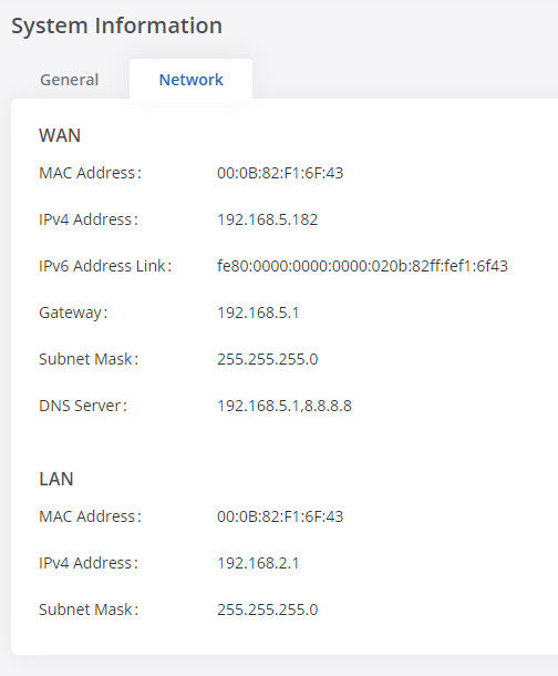
Network
Under Web GUI🡪System Status🡪System Information🡪Network, users could check the network information for the GXW450X. Please see the details in the following table.
WAN/LAN | |
MAC Address | Global unique ID of the device, in HEX format. The MAC address can be found on the label coming with the original box and on the label located at the bottom of the device. |
IPv4 Address | The IPv4 address attributed to the network interface |
IPv6 Address | The IPv6 address attributed to the network interface |
IPv6 Address Link | The IPv6 address Link attributed to the network interface
|
Gateway | Default gateway address.
|
Subnet Mask | Subnet mask address.
|
DNS Server | DNS server address. |
System Information🡪Network
Active Calls
The active calls on the GXW450X are displayed on the Web GUI🡪System Status🡪Active Calls page. Users can monitor call status and hang up active call(s) in a real-time manner.
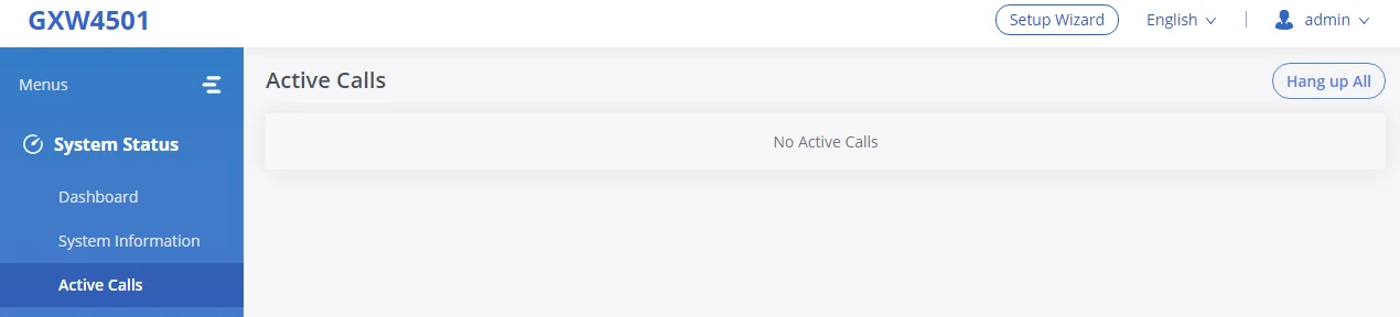
Users can click on “Hang up All” to terminate all the active calls at once.
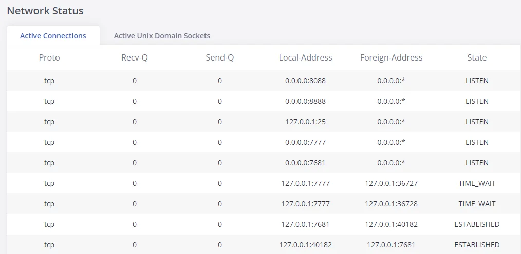
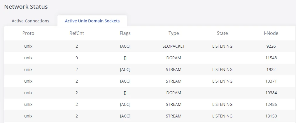
Network status
GXW450X supports Network Status to display active internet connections. Users can use Network Status to troubleshoot connection issues between GXW450X and other services. This information can be found under Web GUI🡪System Status🡪Network Status, the users can view active Internet connections and the Active Unix Domain Sockets.
SYSTEM SETTINGS
This chapter explains configurations for system-wide parameters on the GXW450X. System settings are under the “System Settings” tab on GXW450X Web GUI. System settings include Network Settings, Security Settings, HTTP Server, Email Settings, Time Settings, OpenVPN® settings, and DDNS Settings
HTTP Server
The GXW450X embedded web server responds to HTTP/HTTPS GET/POST requests. Embedded HTML pages allow the users to configure the gateway through a Web browser such as Microsoft IE, Mozilla Firefox, and Google Chrome. By default, the Gateway can be accessed via HTTPS using Port 8089 (e.g., https://192.168.1.50:8089). Users could also change the access protocol and port as preferred under Web GUI🡪System Settings🡪HTTP Server.
Basic Settings | |
Redirect From Port 80 | Enable or disable redirect from port 80. On the gateway, the default access protocol is HTTPS and the default port number is 8089. When this option is enabled, the access using HTTP with Port 80 will be redirected to HTTPS with Port 8089. The default setting is “Enable”. |
Protocol Type | Select HTTP or HTTPS. The default setting is “HTTPS”. This is also the protocol used for zero config when the endpoint device downloads the config file from the GXW450X. |
Port | Specify the port number to access the HTTP server. The default port is 8089. |
Enable IP whitelist | If enabled, only the IP address on the permitted IP list will be allowed to access the GXW450X’s web GUI. |
Permitted IP(s) | Add an IP address to the list of allowed IPs to access GXW450X’s web GUI. Ex: 192.168.6.233 / 255.255.255.255 |
Certificate Settings | |
Options | Select the mode to download SSL certificates for the web server, two modes are available:
Manually Upload certificate: Upload the files while respecting size and format. Automatically request certificate: enter the domain from which to request the certificate files.
|
TLS Private Key | Upload private key for the built-in HTTP server.
Note: The size of the key file must be under 2MB and it will be renamed as “private.pem” automatically. |
TLS Cert | Upload the certificate for the built-in HTTP server and override the existing one.
Note: The size of your certificate must be under 2MB. This is the certificate file (*.pem format only) for TLS connection and it will be renamed as “certificate.pem” automatically. It contains a private key for the client and a signed certificate for the server. |
Reset Certificate | Restore the default key and certificate. The web server needs to reload to take effect after certificate restoration. |
HTTP Server
Network Settings
After successfully connecting the GXW450X to the network for the first time, users could log in to the Web GUI and go to System Settings🡪Network Settings to configure the network parameters for the device. In this section, all the available network setting options are listed. Select each tab on the Web GUI🡪System Settings🡪Network Settings page to configure IPV4 Settings, IPV6 Settings, 802.1X and Static Routes.
Basic Settings
Please refer to the following tables for basic network configuration parameters on GXW450X.
Method | Switch: WAN port interface will be used for the uplink connection. LAN port interface will be used as a room for PC connection. |
MTU | Specifies the Maximum Transmission Unit. (By default, it’s 1492) |
IPv4 Address | |
Preferred DNS Server | Enter the preferred DNS server address. If Preferred DNS is used, GXW450X will try to use it as the Primary DNS server. |
WAN (when Method set to “Route”) / LAN (when Method set to “Switch”) | |
IP Method | Select DHCP, Static IP, or PPPoE. The default setting is DHCP. |
If “IP Method” is set to “Static” | |
IP Address | Enter the IP address for static IP settings. The default setting is 192.168.0.160 |
Subnet Mask | Enter the subnet mask address for static IP settings. The default setting is 255.255.0.0. |
Gateway IP | Enter the gateway IP address for static IP settings. The default setting is 0.0.0.0 |
DNS Server 1 | Enter the DNS server 1 address for static IP settings. |
DNS Server 2 | Enter the DNS server 2 address for static IP settings. |
If “IP Method” is set to “PPPoE” | |
User Name | Enter the user name to connect via PPPoE. |
Password | Enter the password to connect via PPPoE. |
If “IP Method” is set to “DHCP”, “Static” or “PPPoE” | |
Layer 2 QoS 802.1Q/VLAN Tag | Assign the VLAN tag of the layer 2 QoS packets for the LAN port. The default value is 0 (no VLAN Tag). The valid range is between 2 and 4094. |
Layer 2 QoS 802.1p Priority Value | Assign the priority value of the layer 2 QoS packets for the LAN port. The default value is 0. The valid range is between 0 and 7. |
LAN (when Method set to “Route”) | |
IP Address | Enter the IP address. The default setting is 192.168.2.1 |
Subnet Mask | Enter the subnet mask address. The default setting is 255.255.255.0. |
DHCP Server Enable | Enable or disable DHCP server capability. The default setting is “Yes. |
DNS Server 1 | Enter DNS server address 1. The default setting is 8.8.8.8 |
DNS Server 2 | Enter DNS server address 2. The default setting is 208.67.222.222. |
Allow IP Address From | Enter the DHCP IP Pool starting address. The default setting is 192.168.2.100. |
Allow IP Address To | Enter the DHCP IP Pool ending address. The default setting is 192.168.2.254. |
Default Gateway | Configure the default Gateway assigned by the DHCP server. |
Default IP Lease Time | Enter the IP lease time (in seconds). The default setting is 43200. |
Layer 2 QoS 802.1Q/VLAN Tag | Assign the VLAN tag of the layer 2 QoS packets for the LAN port. The default value is 0 (no VLAN Tag). The valid range is between 2 and 4094. |
Layer 2 QoS 802.1p Priority Value | Assign the priority value of the layer 2 QoS packets for LAN port. The default value is 0. The valid range is between 0 and 7. |
IPv6 Address | |
WAN (when “Method” is set to “Route”) / LAN (when “Method” is set to “Switch”) | |
IP Method | Select Auto or Static. The default setting is Auto |
If “IP Method” is set to “Static” |
|
IP Address | Enter the IP address for static IP settings. |
IP Prefixlen | Enter the Prefix length. Default is 64 |
DNS Server 1 | Enter the DNS server 1 address for static settings. |
DNS Server 2 | Enter the DNS server 2 address for static settings. |
LAN (when “Method” is set to “Route”) | |
DHCP Server | Enable or disable DHCP server capability. Available options are: Disable: DHCP Server will be disabled Auto: Stateless address auto-configuration using NDP protocol DHCPv6: Stateful address autoconfiguration using DHCPv6 protocol.
The default setting is “Disable” |
If “DHCP Server” is set to “Auto” or “DHCPv6” | |
DHCP Prefix | Enter DHCP Prefix when static IP is used. Format: “xxxx:xxxx:xxxx:xxxx:xxxx:xxxx:xxxx:xxxx”. Default is “2001:db8:2:2::” |
DHCP Prefixlen | Enter the Prefix length. Default is 64 |
DNS Server 1 | Enter DNS server address 1.
The default setting is “2001:4860:4860::8888”. |
DNS Server 2 | Enter DNS server address 2. The default setting is “2001:4860:4860::8844”. |
If “DHCP Server” is set to “DHCPv6” | |
Allow IP Address From | Enter the DHCP IP Pool starting address. The default setting is “2001:db8:2:2::3000”. |
Allow IP Address To | Enter the DHCP IP Pool ending address. The default setting is “2001:db8:2:2::4000”. |
Default IP Lease Time | Enter the IP lease time (in seconds). The default setting is 43200. |
GXW450X Network Settings🡪Basic Settings
DHCP Client List
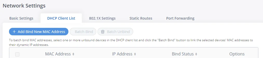
This feature can bind MAC to IP address on the LAN port when GXW450x is set to “Route” mode.
When devices receive IP addresses from the GXW450X LAN port, they will be listed on the web UI under “System Settings 🡪 Network Settings 🡪 DHCP Client List” as shown below.
Users can bind manually a MAC to an IP address by clicking on ![]() , the following figure will pop up.
, the following figure will pop up.
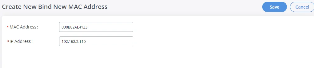
The user needs to set the device MAC address and the IP that will be bound to it (the IP address needs to be within the GXW450X DHCP range).
In order to bind a batch of listed MAC addresses, the user needs to check first the MAC addresses to bind and click on ![]() . A confirmation popup will be shown, click
. A confirmation popup will be shown, click ![]() to bind the addresses.
to bind the addresses.
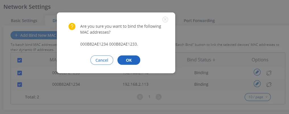
After Clicking “OK” to confirm the binding, the “Bind Status” will change from “Unbind” to “Binding”.
802.1X Settings
IEEE 802.1X is an IEEE standard for port-based network access control. It provides an authentication mechanism to the device before the device can access the Internet or other LAN resources. The GXW450X supports 802.1X as a supplicant/client to be authenticated. The following diagram and figure show the GXW450X uses 802.1X mode “EAP-MD5” on the WAN port as the client in the network to access the Internet.
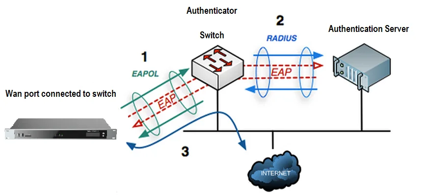
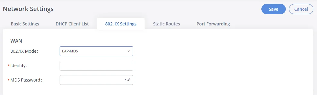
The following table shows the configuration parameters for 802.1X on GXW450X. Identity and MD5 password are required for authentication, which should be provided by the network administrator obtained from the RADIUS server. If “EAP-TLS” or “EAP-PEAPv0/MSCHAPv2” is used as the 802.1X mode, users will also need to upload 802.1X CA Certificate and 802.1X Client Certificate, which should be also generated from the RADIUS server.
802.1X Mode | Select 802.1X mode. The default setting is “Disable”. The supported 802.1X mode is:
|
Identity | Enter 802.1X mode Identity information. |
MD5 Password | Enter 802.1X mode MD5 password information. |
802.1X CA Certificate | Upload 802.1X CA certificate. This file will be renamed as “8021x_ca_cert” automatically. |
802.1X Client Certificate | Upload 802.1X client certificate with both certificate and private key. This file will be renamed as “8021x_client_cert” automatically. |
GXW450X Network Settings🡪802.1X
Static Routes
The GXW450X provides users static routing capability that allows the device to use manually configured routes, rather than information only from dynamic routing or gateway configured in the GXW450X Web GUI🡪System Settings🡪Network Settings🡪Basic Settings to forward traffic. It can be used to define a route when no other routes are available or necessary.
-
Click on
 to create a new IPv4 static route or click on
 to create a new IPv6 static route. The configuration parameters are listed in the table below.
-
Once added, users can select
 to edit the static route.
-
Select
 to delete the static route.
Destination | Configure the destination IPv4 address or the destination IPv6 subnet for the GXW450X to reach using the static route. Example: IPv4 address – 192.168.66.4 IPv6 subnet – 2001:740:D::1/64 |
Netmask | Configure the subnet mask for the above destination address. If left blank, the default value is 255.255.255.255. Example: 255.255.255.0 |
Gateway | Configure the IPv4 or IPv6 gateway address so that the GXW450X can reach the destination via this gateway. The gateway address is optional. Example: 192.168.40.5 or 2001:740:D::1 |
Interface | Specify the network interface on the GXW450X to reach the destination using the static route. |
GXW450X Network Settings🡪Static Routes
Port Forwarding
The GXW450X network interface supports router functions which provide users the ability to do port forwarding. If the GXW450X is set to “Route” under Web GUI🡪System Settings🡪Network Settings🡪Basic Settings: Method, port forwarding is available for configuration.
The port forwarding configuration is under the Web GUI🡪System Settings🡪Network Settings🡪Port Forwarding page. Please see the related settings in the table below.
WAN Port | Specify the WAN port number or a range of WAN ports. An unlimited number of ports can be configured. Note: When it is set to a range, the WAN port, and LAN port must be configured with the same range, such as WAN port: 1000-1005 and LAN port: 1000-1005, and access from the WAN port will be forwarded to the LAN port with the same port number, for example, WAN port 1000 will be port forwarding to LAN port 1000. |
LAN IP | Specify the LAN IP address. |
LAN Port | Specify the LAN port number or a range of LAN ports. Note: When it is set to a range, the WAN port, and LAN port must be configured with the same range, such as WAN port: 1000-1005 and LAN port: 1000-1005, and access from the WAN port will be forwarded to the LAN port with the same port number, for example, WAN port 1000 will be port forwarding to LAN port 1000. |
Protocol Type | Select protocol type “UDP Only”, “TCP Only” or “TCP/UDP” for the forwarding in the selected port. The default setting is “UDP Only”. |
GXW450X System Settings 🡪 Network Settings🡪Port Forwarding
OpenVPN®
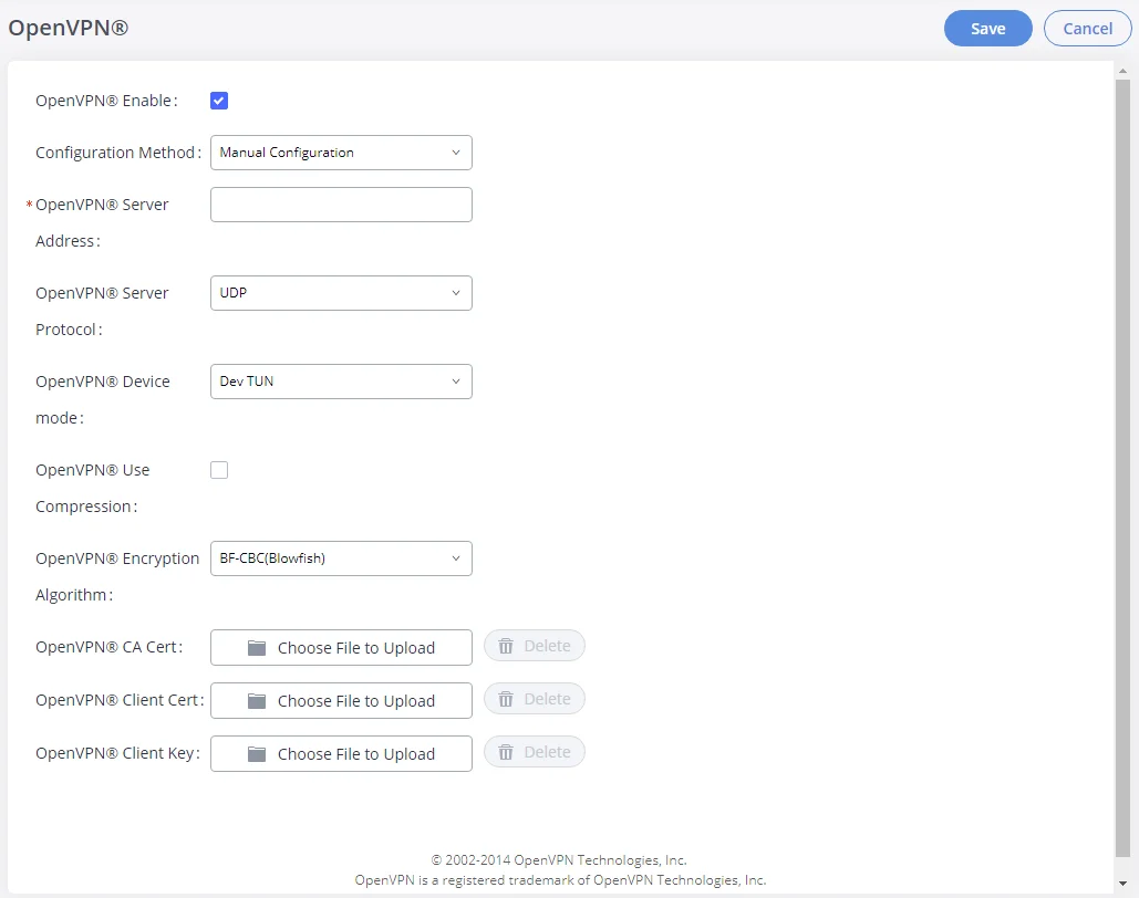
OpenVPN® settings allow the users to configure GXW450X to use VPN features, the following table gives details about the various options in order to configure the GXW450X as OpenVPN Client.
OpenVPN® Enable | Enable / Disable the OpenVPN® feature. The default is “Disabled”. |
Configuration Method | Select the OpenVPN® configuration method.
Manual Configuration. Upload Configuration File. |
If “Configuration Method” is set to “Manual Configuration” | |
OpenVPN® Server Address | Configures the hostname/IP and port of the server. For example, “192.168.1.2:22” or “2001:0DB8:0000:0000:0000:0000:1428:0000”. |
OpenVPN® Server Protocol | Select the same protocol that the OpenVPN® server is using, e.g., select UDP if the OpenVPN® is using UDP. Available options: UDP TCP The default setting is “UDP”. |
OpenVPN® Device Mode | Use the same setting as used on the server. Dev TUN: Create a routed IP tunnel. Dev TAP: Create an Ethernet tunnel.
The default setting is “Dev TUN”. |
OpenVPN® Use Compression | Compress tunnel packets using the LZO algorithm on the VPN link. Don’t enable this unless it is also enabled in the server config file. |
OpenVPN® Encryption Algorithm | Please select a cryptographic cipher from the drop-down list. Use the same setting that you are using on the server. The default setting is “BF-CBC(Blowfish)”. |
OpenVPN® CA Cert | Upload an SSL/TLS root certificate. This file will be renamed as ‘ca.crt’ automatically. |
OpenVPN® Client Cert | Upload a client certificate. This file will be renamed as ‘client.crt’ automatically. |
OpenVPN® Client Key | Upload a client private key. This file will be renamed as ‘client.key’ automatically. |
User Authentication | Enables the authentification by entering the Username and Password credentials , Disabled by Default. |
If “Configuration Method” is set to “Manual Configuration” | |
OpenVPN® Configuration File | Upload Configuration file to with OpenVPN® settings.
Only file with .conf,.ovpn suffix is accepted for OpenVPN® Configuration File. The file size must be under 2MB. |
GXW450X System Settings🡪Network Settings🡪OpenVPN®
DDNS Settings
DDNS setting allows users to access GXW450X via domain name instead of IP address.
The GXW450X supports DDNS service from the following DDNS provider:
- dydns.org
- freedns.afraid.org
- zoneedit.com
- noip.com
- oray.net
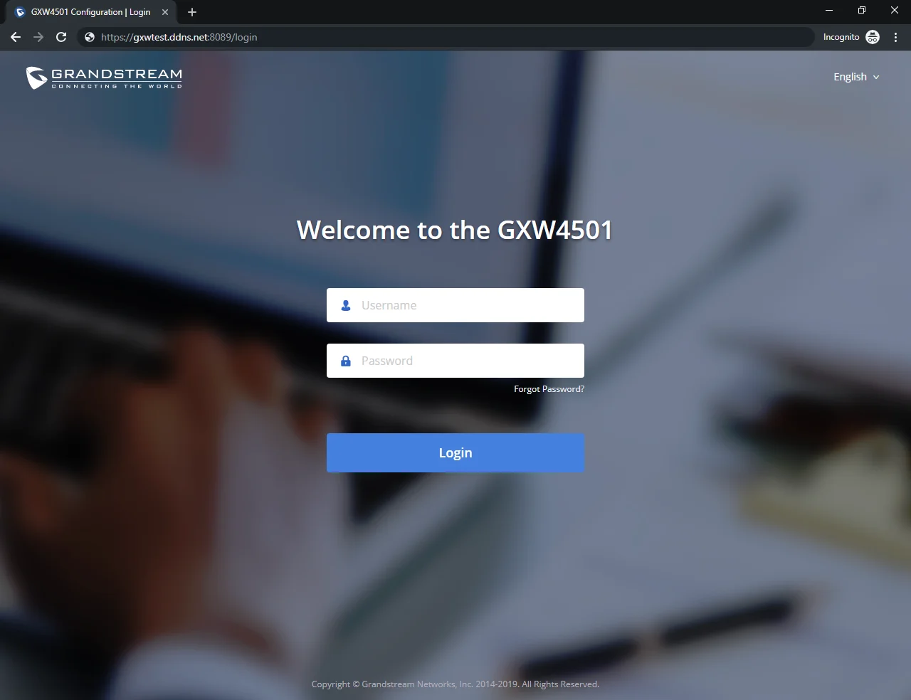
Here is an example of using noip.com for DDNS.
- Register domain in DDNS service provider. Please note the GXW450X needs to have public IP access.
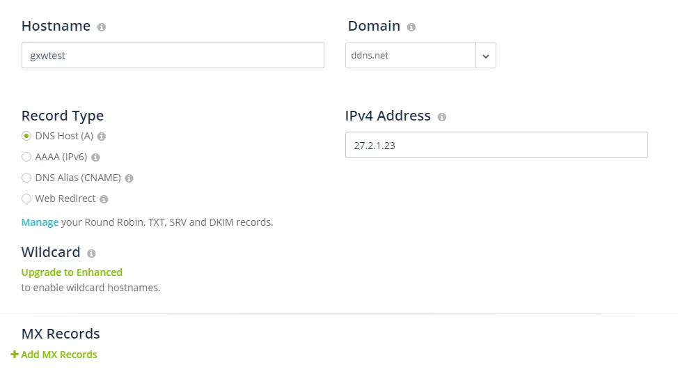
- On Web GUI🡪System Settings🡪Network Settings🡪DDNS Settings, enable DDNS service and configure username, password, and hostname.
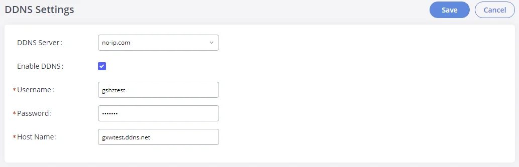
- Now you can use a domain name instead of an IP address to connect to the GXW450X Web GUI.
Security Settings
The GXW450X provides users with firewall security configurations to prevent certain malicious attacks on the GXW450X system. Users could configure to allow, restrict or reject specific traffic through the device for security and bandwidth purpose. The GXW450X also provides the Fail2ban feature for authentication errors in SIP REGISTER, INVITE and SUBSCRIBE. To configure firewall settings in the GXW450X, go to the Web GUI🡪System Settings🡪Security Settings page.
Static Defense
Under the Web GUI🡪System Settings🡪Security Settings🡪Static Defense page, users will see the following information:
- Current service information with port, process, and type.
- Custom firewall settings.
- Typical firewall settings.
The following table shows a sample current service status running on the GXW450X.
Port | Process | Type | Port | Process | Type |
2000 | asterisk | TCP/IPv4 | 67 | dhcpd | UDP/IPv4 |
8088 | asterisk | TCP/IPv4 | 69 | udpsvd | UDP/IPv4 |
8888 | pbxmid | TCP/IPv4 | 37178 | asterisk | UDP/IPv4 |
25 | master | TCP/IPv4 | 80 | lighttpd | TCP/IPv6 |
7777 | asterisk | TCP/IPv4 | master | TCP/IPv6 | |
7681 | pbxmid | TCP/IPv4 | 8089 | lighttpd | TCP/IPv6 |
4520 | asterisk | UDP/IPv4 | 4569 | asterisk | UDP/IPv6 |
4569 | asterisk | UDP/IPv4 | 5060 | asterisk | UDP/IPv6 |
3765 | dhcpd | UDP/IPv4 | 24539 | dhcpd | UDP/IPv6 |
5000 | asterisk | UDP/IPv4 | 54411 | asterisk | UDP/IPv6 |
67 | udhcpd | UDP/IPv4 |
|
GXW450X Static Defense🡪Current Service
Under “Custom Firewall Settings”, users could create new rules to accept, reject or drop certain traffic going through the GXW450X. To create a new rule, click on the “Create New Rule” button and a new window will pop up for users to specify rule options.
Right next to the “Create New Rule” button, there is a checkbox for the option “Reject Rules”. If it’s checked, all the rules will be rejected except the firewall rules listed below. In the firewall rules, only when there is a rule that meets all the following requirements, the option “Reject Rules” will be allowed to check:
- Action: “Accept”
- Type “In”
- The destination port is set to the system login port (e.g., by default 8089)
- The protocol is not UDP
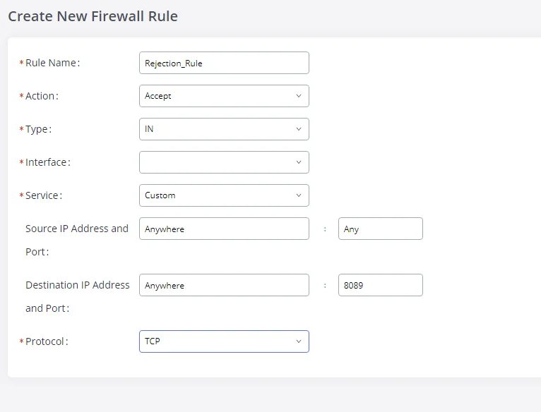
Below is a table listing all the firewall rules settings:
Rule Name | Specify the Firewall rule name to identify the firewall rule. |
Action | Select the action for the Firewall to perform.
|
Type | Select the traffic type.
|
Service | Select the service type.
If “Custom” is selected, users will need to specify Source (IP and port), Destination (IP and port), and Protocol (TCP, UDP, or Both) for the service. Please note if the source or the destination field is left blank, it will be used as “Anywhere”. |
Firewall Rule Settings
Save the change and click on the “Apply” button. Then submit the configuration by clicking on “Apply Changes” on the upper right of the web page. The new rule will be listed at the bottom of the page with sequence number, rule name, action, protocol, type, source, destination, and operation. More operations are below:
-
Click on
to edit the rule.
-
Click on
to delete the rule.
-
Use the arrows up
 ,down
,down
 , to the top
 or to the bottom
 to move the rules up and down.
For typical firewall settings, users could configure the following options on the GXW450X.
Ping Defense Enable | If enabled, ICMP response will not be allowed for Ping requests. The default setting is disabled. To enable or disable it, click on the check box for the LAN or WAN (GXW450X) interface. |
SYN-Flood Defense Enable | Allows the GXW450X to handle excessive amounts of SYN packets from one source and keep the web portal access. There are two options available and only one of these options may be enabled at one time. eth(0)LAN defends against attacks directed to the LAN IP address of the GXW450X. eth(1)WAN defends against attacks directed to the WAN IP address of the GXW450X.
SYN Flood Defense will limit the number of SYN packets accepted by the GXW450X from one source to 10 packets per second. Any excess packets from that source will be discarded. |
Ping-of-Death Defense Enable | Enable to prevent Ping-of-Death attack on the device. The default setting is disabled. To enable or disable it, click on the check box for the LAN or WAN (GXW450X) interface. |
Typical Firewall Settings
Dynamic Defense
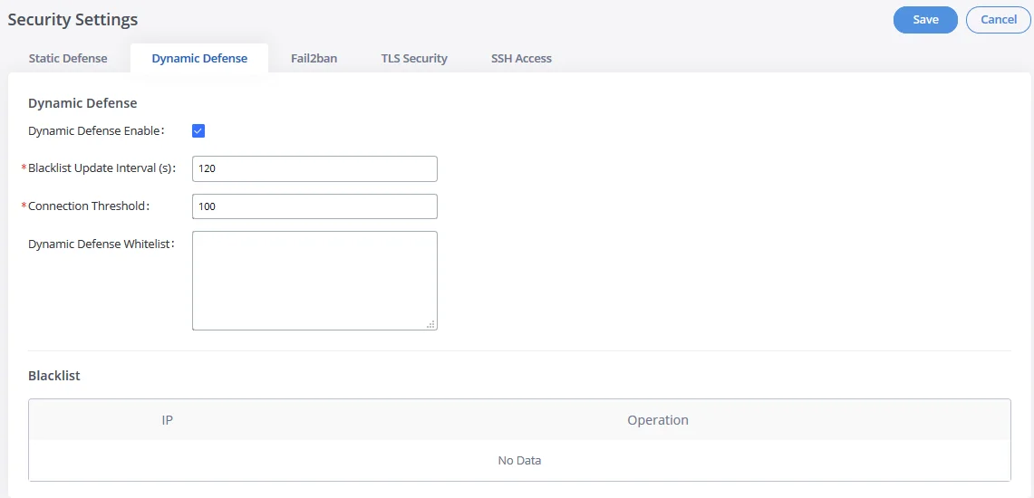
Dynamic defense is supported on the GXW450X series. It can blacklist hosts dynamically when the LAN mode is set to “Route” under the Web GUI🡪System Settings🡪Network Settings🡪Basic Settings page. If enabled, the traffic coming into the GXW450X can be monitored, which helps prevent massive connection attempts or brute force attacks on the device. The blacklist can be created and updated by the GXW450X firewall, which will then be displayed on the web page. Please refer to the following table for dynamic defense options on the GXW450X.
Dynamic Defense Enable | Enable dynamic defense. The default setting is disabled. |
Blacklist Update Interval | Configure the blacklist update time interval (in seconds). The default setting is 120. |
Connection Threshold | Configure the connection threshold. Once the number of connections from the same host reaches the threshold, it will be added to the blacklist. The default setting is 100. |
Dynamic Defense Whitelist | Allowed IPs and ports range, multiple IP addresses, and port range. For example: 192.168.2.10-
192.168.2.20 5060:5061 |
Blacklist | |
Black List | Users will be able to view the IPs that have been blocked by GXW450X. |
GXW450X Firewall Dynamic Defense
The following figure shows a configuration example:
- If a host at IP address 192.168.2.5 initiates more than 100 TCP connections to the GXW450X, it will be added to the GXW450X blacklist. This host 192.168.2.5 will be blocked by the GXW450X for 500 seconds.
- Since IP range 192.168.2.10-192.168.2.20 is in the whitelist, if a host initiates more than 20 TCP connections to the GXW450X within 1 minute, it will not be added to the GXW450X blacklist. It can still establish a TCP connection with the GXW450X.
Fail2Ban
Fail2Ban feature on the GXW450X provides intrusion detection and prevention for authentication errors in SIP INVITE and SUBSCRIBE. Once the entry is detected within “Max Retry Duration”, the GXW450X will act to forbid the host for a certain period as defined in “Banned Duration”. This feature helps prevent SIP brute force attacks on the gateway system.
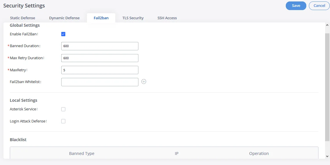
Global Settings | |
Enable Fail2Ban | Enable Fail2Ban. The default setting is disabled. Please make sure both “Enable Fail2Ban” and “Asterisk Service” are turned on to use Fail2Ban for SIP authentication on the GXW450X. |
Banned Duration | Configure the duration (in seconds) for the detected host to be banned. The default setting is 600. If set to 0, the host will be always banned. |
Max Retry Duration | Within this duration (in seconds), if a host exceeds the max times of retry as defined in “MaxRetry”, the host will be banned. The default setting is 600. |
MaxRetry | Configure the number of authentication failures during “Max Retry Duration” before the host is banned. The default setting is 5. |
Fail2Ban Whitelist | Configure IP address, CIDR mask, or DNS host in the whitelist. Fail2Ban will not ban the host with a matching address in this list. Up to 20 addresses can be added to the list. |
Local Settings | |
Asterisk Service | Enable Asterisk service for Fail2Ban. The default setting is disabled. Please make sure both “Enable Fail2Ban” and “Asterisk Service” are turned on to use Fail2Ban for SIP authentication on the GXW450X. |
Listening Port Number | Configure the listening port number for the service. By default, port 5060 will be used for UDP and TCP, and port 5061 will be used for TLS. |
MaxRetry | Configure the number of authentication failures during “Max Retry Duration” before the host is banned. The default setting is 10. Please make sure this option is properly configured as it will override the “MaxRetry” value under “Global Settings”. |
Login Attack Defense | Enables defense against excessive login attacks to the GXW450X’s web GUI. The default setting is disabled. |
Listening Port Number | This is the Web GUI listening port number which is configured under System Settings🡪HTTP Server🡪Port. The default is 8089. |
MaxRetry | When the number of failed login attempts from an IP address exceeds the MaxRetry number, that IP address will be banned from accessing the Web GUI. The default setting is 5 |
Blacklist | |
Black List | Users will be able to view the IPs that have been blocked by GXW450X. |
Fail2Ban Settings
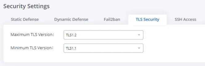
TLS Security
Under the Web GUI🡪System Settings🡪Security Settings🡪TLS security page, users can now select the minimum and maximum versions of TLS for the GXW450x to support.
Maximum TLS Version | Specifies the minimum TLS version on the GXW450x in order to accept TLS connection. |
Minimum TLS Version | Specifies the maximum TLS version on the GXW450x in order to accept TLS connection. |
TLS Security parameters
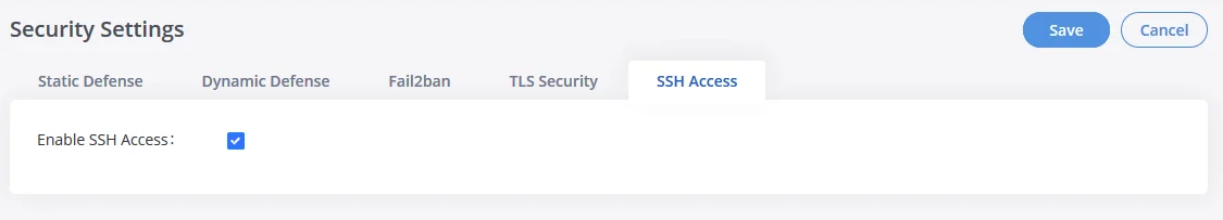
SSH Access
SSH switch is available via Web GUI. Users can enable or disable SSH access directly from the Web GUI or LCD screen. For web SSH access, please log in GXW450X web interface and go to Web GUI🡪System Settings🡪Security Settings🡪SSH Access. By default, SSH access is disabled for security concerns. It is highly recommended to only enable SSH access for debugging purposes
Time Settings
Automatic Date and Time
The current system time on the GXW450X can be found under Web GUI🡪System Status🡪Dashboard🡪PBX Status.
To configure the GXW450X to update the time automatically, go to Web GUI🡪System Settings🡪Time Settings🡪Automatic Date and Time.
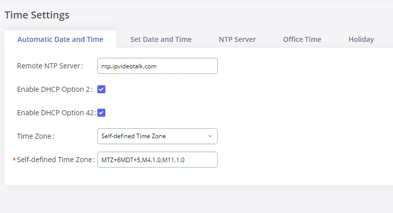
Remote NTP Server | Specify the URL or IP address of the NTP server for the GXW450X to synchronize the date and time. The default NTP server is ntp.ipvideotalk.com. |
Enable DHCP Option 2 | If set to “Yes”, the GXW450X can get provisioned for Time Zone from DHCP Option 2 in the local server automatically. The default setting is “Yes”. |
Enable DHCP Option 42 | If set to “Yes”, the GXW450X can get provisioned for NTP Server from DHCP Option 42 in the local server automatically. This will override the manually configured NTP Server. The default setting is “Yes”. |
Time Zone | Select the proper time zone option so the GXW450X can display the correct time accordingly.
If “Self-Defined Tome Zone” is selected, please specify the time zone parameters in the “Self-Defined Time Zone” field as described in the below option. |
Self-Defined Time Zone | If “Self-Defined Time Zone” is selected in the “Time Zone” option, users will need to define their own time zone following the format below. The syntax is: std offset dst [offset], start [/time], end [/time] Default is set to: MTZ+6MDT+5,M4.1.0,M11.1.0
MTZ+6MDT+5
This indicates a time zone with 6 hours offset and 1 hour ahead for DST, which is U.S central time. If it is positive (+), the local time zone is west of the Prime Meridian (A.K.A: International or Greenwich Meridian); If it is negative (-), the local time zone is east.
M4.1.0,M11.1.0
The 1st number indicates Month: 1,2,3.., 12 (for Jan, Feb, .., Dec). The 2nd number indicates the nth iteration of the weekday: (1st Sunday,
3rd Tuesday…). Normally 1, 2, 3, 4 are used. If 5 is used, it means the last iteration of the weekday.
The 3rd number indicates weekday: 0,1,2,..,6 ( for Sun, Mon, Tues, … ,Sat).
Therefore, this example is the DST which starts on the First Sunday of
April to the 1st Sunday of November. |
Automatic Date and Time Settings
Set Date and Time
To manually set the time on the GXW450X, go to Web GUI🡪System Settings🡪Time Settings🡪Set Date and Time. The format is YYYY-MM-DD HH:MM:SS.
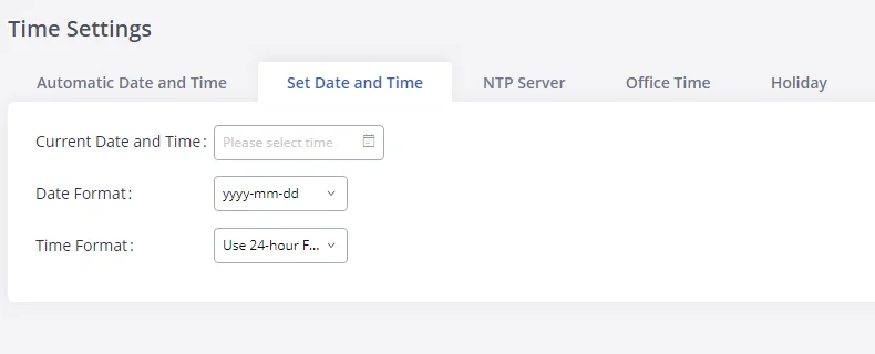
Current Date and Time | Manually set up the system time. If the system time is automatically set up successfully, the manually configured value will not take effect. |
Date Format | Configure the global date format, the default format is yyyy-mm-dd. |
Time Format | Chooses the format that will be used to display the Time, 24-hour format or 12-hour format, the default setting is the 24-hour format |
Date and Time Manual Settings
NTP Server
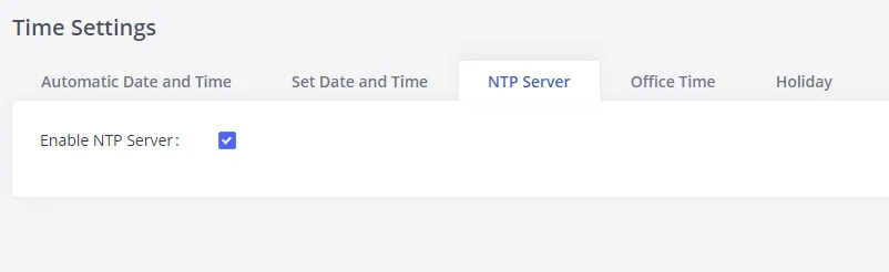
The GXW450X can be used as an NTP server for the NTP clients to synchronize their time. To configure the GXW450X as the NTP server, set “Enable NTP server” to “Yes” under Web GUI🡪System Settings🡪Time Settings🡪NTP Server. On the client side, point the NTP server address to the GXW450X IP address or hostname to use the GXW450X as the NTP server.
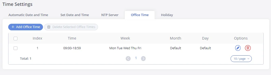
Office Time
On the GXW450X, the system administrator can define “office time”, which can be used to configure time conditions for the inbound rule schedule. To configure office time, go to Web GUI🡪System Settings🡪Time Settings🡪Office Time. Click on “Add Office Time” to create an office time.
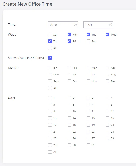
Time | Configure the start time and end time for office hours. |
Week | Select the work days in one week. |
Show Advanced Options | Check this option to show advanced options. Once selected, please specify the “Month” and “Day” options. |
Month | Select the months for office time. |
Day | Select the work days in one month. |
Office Time Settings
Select “Time” and the day for the “Week” for the office time. The system administrator can also define the month and day of the month as advanced options. Once done, click on “Save” and then “Apply Change” for the office time to take effect. The office time will be listed on the web page as the figure shows below.
-
Click on
 to edit the office time.
-
Click on
 to delete the office time.
- Click on “Delete Selected Office Times” to delete multiple selected office times at once.
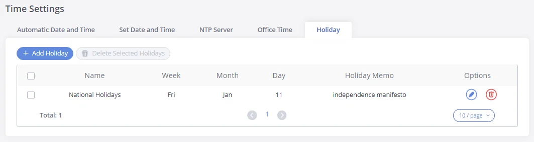
Holiday
On the GXW450X, the system administrator can define “holiday”, which can be used to configure time conditions for the inbound rule schedule. To configure holiday, go to Web GUI🡪System Settings🡪Time Settings🡪Holiday. Click on “Add Holiday” to create holiday time.
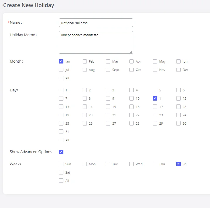
Name | Specify the holiday name to identify this holiday. |
Holiday Memo | Create a note for the holiday. |
Month | Select the month for the holiday. |
Day | Select the day for the holiday. |
Show Advanced Options | Check this option to show advanced options. If selected, please specify the days as holidays in one week below. |
Week | Select the days as holidays in one week. |
Holiday Settings
Enter holiday “Name” and “Holiday Memo” for the new holiday. Then select “Month” and “Day”. The system administrator can also define days in one week as advanced options. Once done, click on “Save” and then “Apply Change” for the holiday to take effect. The holiday will be listed in the web page as the figure shows below.
-
Click on
to edit the holiday.
-
Click on
to delete the holiday.
- Click on “Delete Selected Holidays ” to delete multiple selected holidays at once.
Email Settings
Email Settings Configuration
The Email application on the GXW450X can be used to send out alert event Emails, retrieve admin password, etc. The configuration parameters can be accessed via Web GUI🡪System Settings🡪Email Settings🡪Email Settings.
TLS Enable | Enable or disable TLS during transferring/submitting your Email to another SMTP server. The default setting is “Yes”. |
Type | Select Email type. MTA: Mail Transfer Agent. The Email will be sent from the configured domain. When MTA is selected, there is no need to set up an SMTP server for it, or no user login is required. However, the Emails sent from MTA might be considered spam by the target SMTP server. Client: Submit Emails to the SMTP server. An SMTP server is required, and users need log in with the correct credentials. |
Email Template Sending | Select the email template format to be sent. The “HTML” format is compatible with most mail clients and is recommended. If the mail client does not support the “HTML” format, please select the “Plain Text” format. |
Domain | Specify the domain name to be used in the Email when using the type “MTA”. |
SMTP Server | Specify the SMTP server when using the type “Client”. |
Enable SASL Authentication | Enable SASL Authentication. When disabled, GXW450X will not try to use the user name and password for mail client login authentication. Most of the mail server requires login authentication while some other private mail servers allow anonymous login which requires disabling this option to send Email as normal. For Exchange Server, please disable this option. |
Username | A username is required when using the type “Client”. Normally it’s the Email address. |
Password | Password to login for the above Username (Email address) is required when using the type “Client”. |
POP/POP3 Server Address | Configure the POP/POP3 server address for the configured username Example: pop.gmail.com |
POP/POP3 Server Port | Configure the POP/POP3 server port for the configured username Example: 995 |
Display Name | Specify the display name in the FROM header in the Email. |
Sender | Specify the sender’s Email address.
For example pbx@example.mycompany.com. |
Email Settings
The following figure shows a sample Email setting on the GXW450X, assuming the email is using the default SMTP server of Gmail.
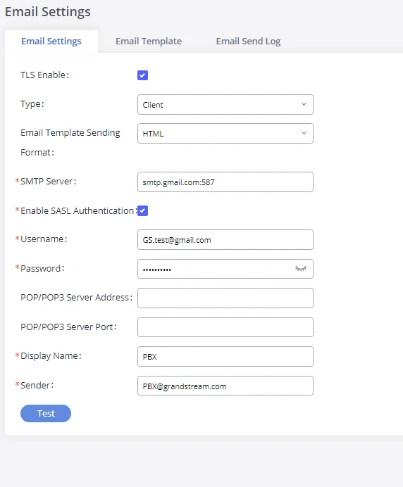
Once the configuration is finished, click on “Test”. In the prompt, fill in a valid Email address to send a test Email to verify the Email settings on the GXW450X.
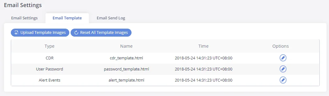
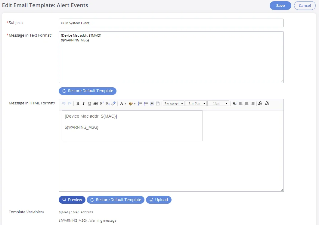
Email Template
The Email templates on the GXW450X can be used for email notification. The configuration parameters can be accessed via Web GUI🡪System Settings🡪Email Settings🡪Email Templates.
-
Press on
 to upload pictures to be used on email templates.
-
Press
 to reset all email templates to default ones.
-
To configure the email template, click the
 button under Options column, and edit the template as desired.
-
Users can preview mail sample by clicking on
 .
.
-
Click on
 in order to restore the default email template.
-
Finally, users can click on
 to upload a custom picture to the email template to display their own logo in the sent mails for example
Email Send Log
Under GXW450X Web GUI🡪System Settings🡪Email Settings🡪Email Send Log, users could search, filter, and check whether the Email is sent out successfully or not. This page will also display the corresponding error message if the Email is not sent out successfully.
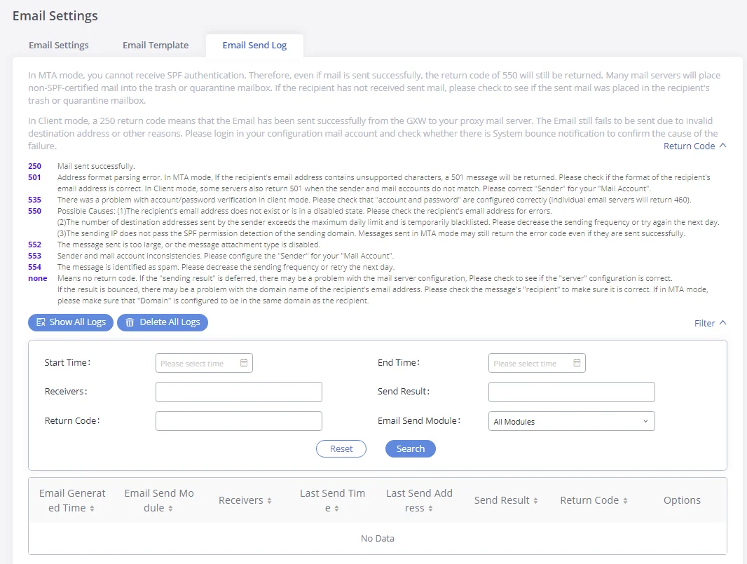
Field | Description |
Start Time | Enter the start time for the filter |
End time | Enter the end time for the filter |
Receivers | Enter the email recipient, while searching for multiple recipients, please separate them with a comma and no spaces. |
Send result | Enter the status of the send result to filter with |
Return code | Enter the email code to filter with |
Email send module | Select the email module to filter from the drop-down list, which contains: All modules; User password; Alert events; CDR; Test. |
Email Send Log
SNMP
GXW450x supports SNMP (Simple Network Management Protocol) which is widely used in network management for network monitoring for collecting information about monitored devices. To configure SNMP settings, go to GXW450x Web GUI→System Settings→SNMP.
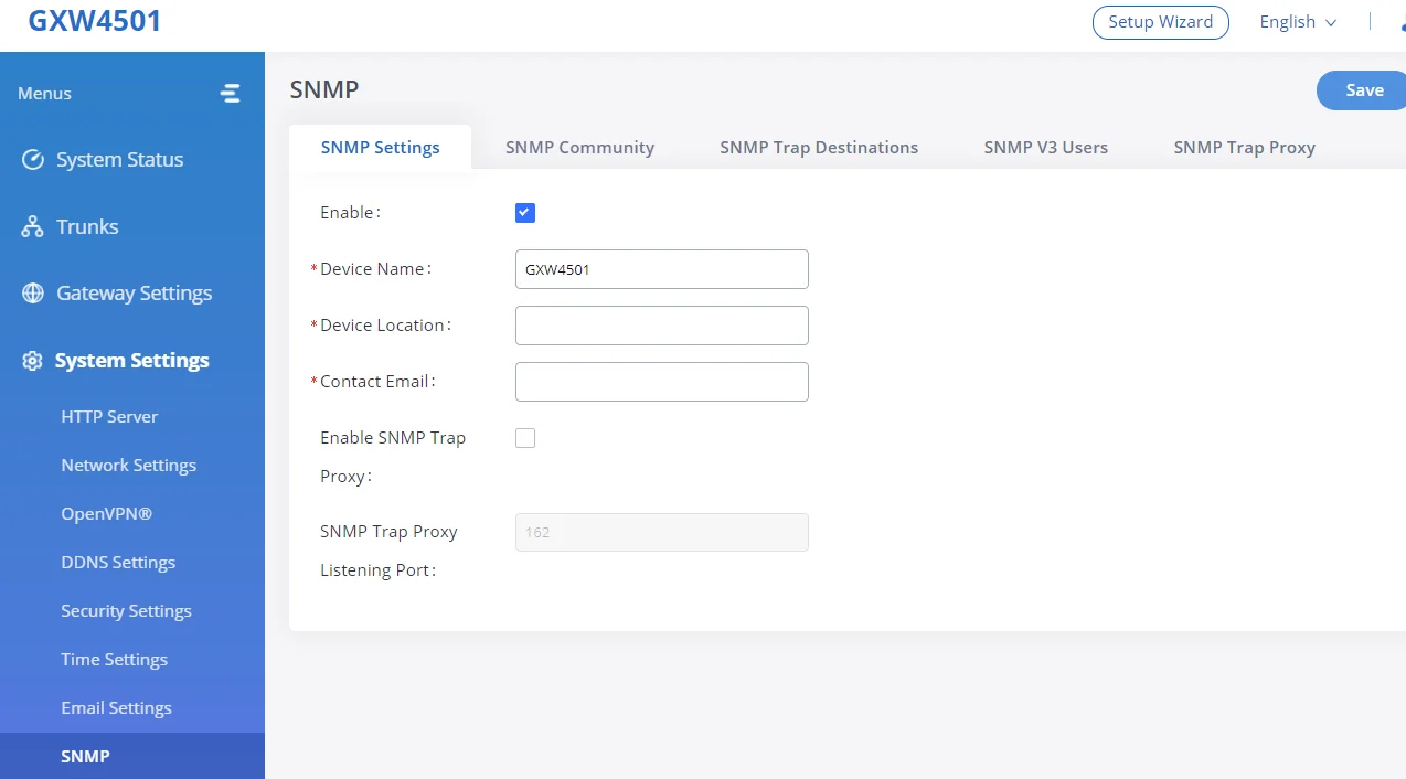
This page has five tabs: SNMP Settings, SNMP Community, SNMP Trap Destination, SNMP V3 Users, and SNMP Trap Proxy. Please refer to the below tables for each tab.
SNMP Settings | |
Enable | Enables SNMP feature. Default is Disabled. |
Device Name | Configures the Device Name. |
Device Location | Configures the Device Location. |
Contact Email | Configures the email address of the administrator on which to receive notifications. |
Enable SNMP Trap Proxy | Enables the SNMP Trap Proxy. Default is Disabled. |
SNMP Trap Proxy Listening Port | Configures the SNMP Trap Proxy Listening Port. The default port is 162. |
SNMP Community | |
Name | Community string associated with the trap. It must match the community string of the trap receiver. |
Access Level | Configure the access level. Two levels are available:
Read only: Can view the device configuration. Read/Write: Can view and change the device configuration. |
SNMP Trap Destinations (GXW450x as managed device) | |
Name | Configure the Name for the SNMP Trap Destination. |
IP Address | The IP address of the SNMP trap receiver. |
Port | Configure the SNMP trap receiver listening port. |
Community | Community is by default set to Public, as community strings for SNMP v1 and v2 aren’t encrypted. |
Type | They are 3 available types: Trapsink: to send SNMP v1 traps
Trap2sink: to send SNMP v2 traps. Informsink: to send inform notification. |
SNMP V3 Users | |
Name | Configure the Name of the SNMP v3 Users. |
Authentication Protocol | Authentication Protocol for SNMPv3. Available protocols are MD5 and SHA. |
Authentication Password | Authentication Password for SNMPv3. |
Privacy Protocol | Privacy protocol for SNMPv3. Available protocols are: DES, AES-128, AES-192, AES-256. |
Privacy Password | Privacy password for SNMPv3. |
Group Level | Configure the group level, two levels are available: Read only: Can view the device configuration. Read/Write: Can view and change the device configuration. |
SNMP Trap Proxy (GXW450x as Trap Proxy) | |
Name | Configures the Name of the SNMP Trap Proxy.
Note: “Enable SNMP Trap Proxy” needs to be toggled on. |
IP Address | Configure the IP address of the SNMP manager. |
Port | Configure the SNMP manager listening port. |
SNMP Parameters
TR-069
The GXW450x series supports TR-069 for remote management of equipment by service providers, reducing on-site visits and downtime.To configure SNMP settings, go to GXW450x Web GUI→System Settings→SNMP.
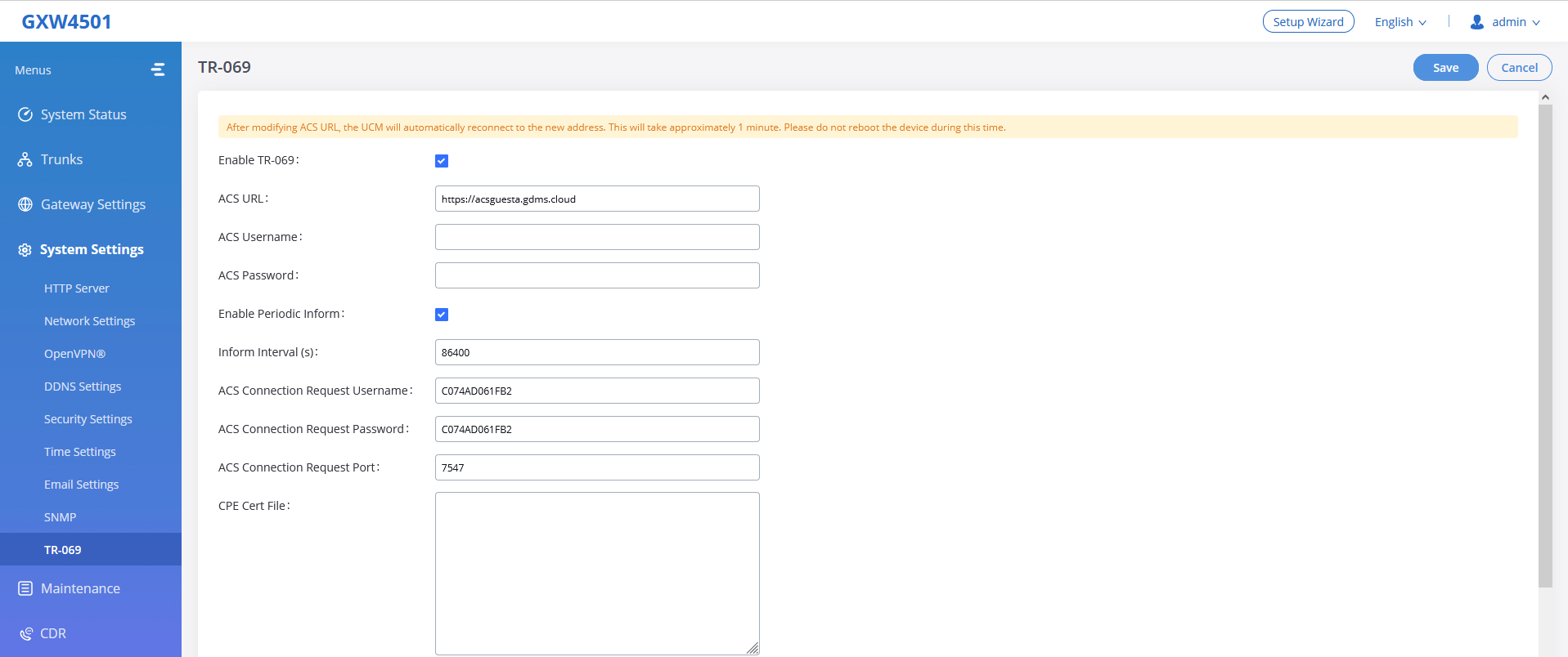
Enable TR-069 | Sets the device to enable the “CPE WAN Management Protocol” (TR-069). The default setting is “No”. Note: Reboot the device to make changes take effect. |
ACS URL | Specifies URL of TR-069 ACS (e.g, https://acsguesta.gdms.cloud), or IP address. |
ACS Username | Enters username to authenticate to ACS. |
ACS Password | Enters password to authenticate to ACS. |
Enable Periodic Inform | Sends periodic inform packets to ACS. The default is “No”. |
Inform Interval (s) | Configures to send
periodic “Inform” packets to ACS based on a
specified intervals. The default setting is 86400. |
ACS Connection Request Username | Enters username for the ACS to connect to the device. |
ACS Connection Request Password | Enters the password for the ACS to connect to the device. |
ACS Connection Request Port | Enters the port for the ACS to connect to the device. |
CPE Cert File | Uploads Cert File for the device to connect to the ACS via SSL. |
CPE Cert Key | Uploads Cert Key for the device to connect to the ACS via SSL. |
TR-069 Settings
GATEWAY TRUNKS
GXW450X is a VoIP Digital Gateway that supports both trunk modes Digital and VoIP to ensure a smooth integration of digital and VoIP communication to connect the legacy telephony infrastructure made up of PRI (E1, T1, J1) to the IP network.
Digital Trunks
The GXW450X supports E1/T1/J1 which are physical connection technologies used in the digital network. T1 is the North American standard, J1 is used in Japan, whereas E1 is the European standard. GXW450X supports four signaling protocols: PRI_NET, PRI_CPE, MFC/R2, and SS7. PRI provides a varying number of channels depending on the standards in the country of implementation (E1, T1, or J1); MFC/R2 is a signaling protocol heavily used over E1 trunks; SS7 uses out-of-band signaling, which travels on a separate, dedicated channel rather than within the same channel as the telephone call, providing more efficiency and higher security level when the telephone calls are set up.
To set up a digital trunk on the GXW450X:
- Go to Web GUI🡪Gateway Settings🡪Interface Settings🡪Digital Hardware to configure port type and channels.
- Go to Web GUI🡪Trunks🡪Digital Trunks to add and edit the digital trunks.
- Go to Web GUI🡪 Trunks🡪Outbound Routes and Inbound Routes to configure outbound and inbound rules for the digital trunk.
Digital Hardware Configuration
Go to Web GUI🡪 Gateway Settings🡪Interface Settings🡪Digital Hardware page and configure the following:
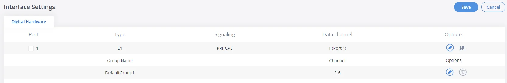
- Click on
 to edit digital ports. Please see configuration parameters in the tables below:
 - Click on to edit group. This assigns channels to be used for the digital port. For E1, 30 B channels can be assigned to the default group; for T1/J1, 23 B channels can be assigned to the default group.
- If fewer than 30 B channels for E1 or 23 B channels for T1/J1 are assigned in the default group, users can click on to add more groups. This is not necessary in most cases and only the default group is needed.
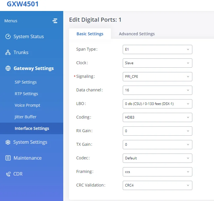
The GXW450X currently supports E1, T1, and J1 digital hardware types. When different signaling is selected for E1, T1, or J1, the settings in basic options and advanced options will be different. The following tables list all the settings to configure digital ports when selecting each signaling.
- Signaling Type: E1 – PRI_NET/PRI_CPE
Basic Settings | |
Clock | All E1/T1/J1 spans generate a clock signal on their transmit side. The parameter determines whether the clock signal from the far end of the E1/T1/J1 is used as the master source of clock timing. If the far end is used as the master, the gateway system clock will synchronize to it. |
Signaling | Chooses the signaling protocol that will be used on the digital port, the available options are : PRI_NET, PRI_CPE, SS7, and MFC/R2 |
Data channel | Chooses the Data Channel for control. |
LBO | The line build-out (LBO) is the distance between the operators and the gateway. Please use the default value of 0dB unless the distance is long. |
Coding | T1: “AMI” or “B8ZS” |
RX Gain | Configure the RX gain for the receiving channel of the digital port. The valid range is from -24dB to +12dB. |
TX Gain | Configure the TX Gain for the transmitting channel of the digital port. The valid range is -24dB to +12dB. |
Codec | Select alaw or ulaw. If set to default, alaw will be used for E1. |
Framing | If the span type is E1, the signaling configured as MFC/R2, then framing must configure as “cas”; If the span type is E1, the signaling configured as PRI or SS7, then framing must configure as “ccs”; If span type is T1, and the signaling configures as PRI or SS7, then framing can configure as “esf” or “d4”; |
CRC Validation | For E1, select whether to use CRC4 or None. |
Advanced Settings | |
Switch Type | Select switch type. |
PRI Dial Plan | This setting is used to specify the type of the callee number. The service provider will usually verify this. The default setting is “unknown”. In some very unusual circumstances, you may need set it to “Dynamic” or “Redundant”. |
PRI Local Dial Plan | This setting is used to specify the type of caller number. The service provider will usually verify this. |
International Prefix | Configure the prefix in PRI Local Dial Plan and PRI Dial Plan for each type. |
PRI T310 | Configure PRI T310 Timer (in seconds). |
PRI Indication | Select the PRI Indication. inband: use in-band tones to play busy or congestion signals to the other side. This is the default setting. |
Reset Interval | The interval that restarts idle channels. |
PRI Exclusive | This setting is used to set up the ChannelD in the SETUP message. If enabled, only the specified B channel can be used. Otherwise, select one of the channels in the B channel. If you need to override the existing channels selection routine and force all PRI channels to be marked as exclusively selected, please enable it. |
Facility Enable | If selected, the transmission of facility-based ISDN supplementary services (such as caller name from CPE over facility) will be enabled. |
SETUP ACK | When receiving a remote “SETUP” SIP message, and the “Sending Complete” field is not included in it, the gateway will send a “SETUP ACK” to request more information. This option should be used if a remote device has “SETUP ACK” support issues. |
Overlap Dial | Configure this option to send overlap digits. If enabled, the SETUP message can include some digits of the callee number, and the rest of the digits can be sent using the INFORMATION message. If disabled, the callee number will be sent via SETUP message when all the digits are ready. |
NSF | Some switches (AT&T especially) require network-specific facilities. Currently the supported values are “none”, “sdn”, “megacom”, “tollfreemegacom”. |
PROGRESS | If enabled, GXW450x can send a signaling message to the calling party indicating that the call is still in progress and that the called party has not yet answered. This can be helpful in situations where the call setup time is longer than expected, or when there may be delays in the network. |
Anonymous call IE | If enabled, the parameter value of the Calling Party Number IE Presentation field in the SETUP message of PRI trunk outgoing anonymous call is Presentation Restricted, or the Calling Party Number IE is not carried in the SETUP message, this effectively means that the caller's number will be hidden, making the call anonymous. |
Play Local MoH | If enabled, the MoH will be played to PRI while holding the SIP trunk call. |
Digital Hardware Configuration Parameters: E1 – PRI_NET/PRI_CPE
- Signaling Type: E1 – SS7
Basic Settings | |
Clock | All E1/T1/J1 spans generate a clock signal on their transmit side. The parameter determines whether the clock signal from the far end of the E1/T1/J1 is used as the master source of clock timing. If the far end is used as the master, the gateway system clock will synchronize to it. Master: The port will never be used as a source of timing. This is appropriate when you know the far end should always be a slave to you. |
Signaling | Chooses the signaling protocol that will be used on the digital port, the available options are : PRI_NET, PRI_CPE, SS7, and MFC/R2 |
Data channel | The Data channel for control. Specifies the channel to use for data connections when PRI_NET or PRI_CPE is chosen as a signaling protocol. While, the first dropdown list specifies the E1/T1 port to use, and the second specifies the channel to use for data connections when SS7 is chosen. |
SS7 Variant | Select ITU, ANSI, or CHINA. |
Originating Point Code | Originating point code is used to identify the node originating the message, always provided by the operator/ISP. |
Destination Point Code | The destination point code is the address to send the message to, always provided by the operator/ISP. |
First CIC | When Span Type is E1, ITU & CHINA Range: [0, 4065], ANSI Range: [0, 16353]. |
Assign CIC To D-channel | If set to yes, D-channel will be assigned a CIC. Else, D-channel will not be assigned. By default, it is set to No. |
Network Indicator | Network Indicator (NI) should match in nodes, otherwise, it might cause issues. Users can select “National”, “National Spare”, “International”, or “International Spare”. Usually, “National” or “International” is used. |
LBO | The line build-out (LBO) is the distance between the operators and the gateway. Please use the default value of 0dB unless the distance is long. |
Coding | T1:”AMI” or “B8ZS” And E1:”AMI” or “HDB3” |
RX Gain | Configure the RX gain for the receiving channel of the digital port. The valid range is from -24dB to +12dB. |
TX Gain | Configure the TX Gain for the transmitting channel of the digital port. The valid range is -24dB to +12dB. |
Codec | Select alaw or ulaw. If set to default, alaw will be used for E1. |
Framing | If the span type is E1, the signaling configured as MFC/R2, then framing must configure as “cas”; If the span type is E1, the signaling configured as PRI or SS7, then framing must configure as “ccs”; If span type is T1, and the signaling configured as PRI or SS7, then framing can configure as “esf” or “d4”; If span type is J1, and the signaling configured as PRI or SS7, then framing can configure as “esf” or “d4”. |
CRC Validation | For E1, select whether to use CRC4 or None. |
Advanced Settings | |
Called Nature of Address Indicator | Indicates the type of the called number. The receiving switch may use this indicator during translations to apply the number’s proper dial plan. Users can select “Unknown”, “Subscriber”, “National”, “International” or “Dynamic”. |
Calling Nature of Address Indicator | Indicates the type of the calling number. The receiving switch may use this indicator during translations to apply the number’s proper dial plan. Users can select “Unknown”, “Subscriber”, “National”, “International” or “Dynamic”. |
Orginal Called | This option decides on SS7 trunk outgoing calls,By controlling the "original called number IE" (Information Element) in SS7 signaling messages, the user can ensure that the correct phone number is displayed to the recipient of a call, even when the call has been rerouted or redirected. Example: if a call is routed through multiple networks or carriers, the "original called number" information can be lost or modified along the way. However, by using this SS7 option, the user can preserve the original called number and ensure that it is displayed correctly to the recipient. |
Early ACM | Early ACM can be used to provide immediate feedback to callers that their call is being connected, as opposed to hearing silence or ringing until the call is actually connected to the intended party. This can help to reduce perceived wait times and improve the overall user experience. If enabled, When an inbound call is received by the gateway, the gateway can signal to the calling party that the call is being connected and that the called party will begin ringing. This early answer supervision signal is sent by the gateway before the called party's phone rings. Disabled by Default. |
Screening Indicator | Sets the screening indicator value for SS7 trunk outgoing calls, indicating passthrough the caller's screening indicator value, This option allows users to modify the screening value, which determines how the network handles the verification of the calling party's number, the available options are:
The default value is set to "Default" |
International Prefix | Configure the prefix in Called Nature of Address Indicator and Calling Nature of Address Indicator for each type. |
Digital Hardware Configuration Parameters: E1 – SS7
- Signaling Type: E1 – MFC/R2
Basic Settings | |
Clock | All E1/T1/J1 spans generate a clock signal on their transmit side. The parameter determines whether the clock signal from the far end of the E1/T1/J1 is used as the master source of clock timing. If the far end is used as the master, the gateway system clock will synchronize to it. Master: The port will never be used as a source of timing. This is appropriate when you know the far end should always be a slave to you. Slave: The equipment at the far end of the E1/T1 link is the preferred source of the master clock. |
Signaling | Chooses the signaling protocol that will be used on the digital port.
PRI: when one end is set to NET, the other end should be set to CPE |
Data channel | Chooses the Data Channel for control. The user can group multiple E1 lines with a single data channel. |
Variant | MFC/R2 multinational adaption. GXW450X supports MFC/R2 standards by ITU and MFC/R2 standards in different countries or regions including Argentina, Brazil, China, Czech Republic, Colombia, Ecuador, Indonesia, Mexico, the Philippines, and Venezuela. |
Category | Defines the Caller Category. Users can choose among the following options: National Subscriber, National Priority Subscriber, International Subscriber, and International Priority Subscriber. |
Get ANI First | If enabled, the callee side will request the caller to send the caller number first and then called number. Note: Options “Get ANI First” and “Skip Category” cannot be enabled at the same time. |
LBO | The line build-out (LBO) is the distance between the operators and the gateway. Please use the default value of 0dB unless the distance is long. |
Coding | T1: “AMI” or “B8ZS” E1: “AMI” or “HDB3” |
RX Gain | Configure the RX gain for the receiving channel of the digital port. The valid range is from -24dB to +12dB. |
TX Gain | Configure the TX Gain for the transmitting channel of the digital port. The valid range is -24dB to +12dB. |
Framing | If the span type is E1, the signaling configured as MFC/R2, then framing must configure as “cas”; If the span type is E1, the signaling configured as PRI or SS7, then framing must configure as “ccs”;
If the span type is T1, and the signaling configured as PRI or SS7, then framing can configure as “esf” or “d4”;
If span type is J1, and the signaling configured as PRI or SS7, then framing can configure as “esf” or “d4”. |
CRC Validation | For E1, select whether to use CRC4 or None. |
Advanced Settings | |
MF Back Timeout (ms) | MFC/R2 value in milliseconds for MF timeout. Values smaller than 500ms are not recommended. -1 represents the default value. |
Metering Pulse Timeout (ms) | MFC/R2 value in milliseconds for the metering pulse timeout. Metering pulse is sent by some telcos for some R2 variants during a call presumably for billing purposes to indicate costs. Should not last more than 500ms, -1 represents the default value, and for Argentina, the default value is 400ms, for others is 0ms. |
Allow Collect Calls | Brazil has a special calling party category for collect calls (llamadas por cobrar) instead of using the operator (as in Mexico). The R2 spec in Brazil says a special GB tone should be used to reject collect calls. By default, this is disabled, which means collect calls will be blocked. |
Double Answer | Some gateways require a double-answer process to block collect calls. If users have a problem blocking collect calls using Group B signals, please try enabling this option. |
Accept On Offer | By default, it’s enabled. In most cases, this option should be enabled. |
Skip Category | If enabled, the callee side will request the caller to send the caller category before sending the caller number. Note: “Get ANI First” and “Skip Category” cannot be enabled at the same time. |
Charge Calls | Whether or not to report to the other end “accept call with charge”. This setting has no effect on most telecoms. The default setting is enabled (recommended). |
Custom Options | Click on the “Custom Options” button (on the left top of the configuration dialog) and then the user can customize desired tone and timer options accordingly. |
Digital Hardware Configuration Parameters: E1 – MFC/R2
- Signaling Type: T1/J1 – PRI_NET/PRI_CPE
Basic Settings | |
Clock | All E1/T1/J1 spans generate a clock signal on their transmit side. The parameter determines whether the clock signal from the far end of the E1/T1/J1 is used as the master source of clock timing. If the far end is used as the master, the gateway system clock will synchronize to it. |
Signaling | Chooses the signaling protocol that will be used on the digital port. |
Data channel | Chooses the Data Channel for control. |
LBO | The line build-out (LBO) is the distance between the operators and the gateway. Please use the default value of 0dB unless the distance is long. |
Coding | T1: “AMI” or “B8ZS” |
RX Gain | Configure the RX gain for the receiving channel of the digital port. The valid range is from -24dB to +12dB. |
TX Gain | Configure the TX Gain for the transmitting channel of the digital port. The valid range is -24dB to +12dB. |
Codec | Select alaw or ulaw. If set to default, ulaw will be used for T1/J1. |
Framing | Select “esf” or “d4”. The default setting is esf. |
Advanced Settings | |
Switch Type | Select switch type. Q.SIG |
PRI Dial Plan | This setting is used to specify the type of the callee number. The service provider will usually verify this. The default setting is “unknown”. In some very unusual circumstances, you may need set it to “Dynamic” or “Redundant”. |
PRI Local Dial Plan | This setting is used to specify the type of caller number. The service provider will usually verify this. |
International Prefix | Configure the prefix in PRI Local Dial Plan and PRI Dial Plan for each type. |
PRI T310 | Configure PRI T310 Timer (in seconds). The default value is 10 seconds. |
PRI Indication | Select the PRI Indication. |
Reset Interval | The interval that restarts idle channels. |
PRI Exclusive | This setting is used to set up the ChannelID in the SETUP message. If enabled, only the specified B channel can be used. Otherwise, select one of the channels in the B channel. If you need to override the existing channels selection routine and force all PRI channels to be marked as exclusively selected, please enable it. |
Facility Enable | If selected, the transmission of facility-based ISDN supplementary services (such as caller name from CPE over facility) will be enabled. |
SETUP ACK | When receiving a remote “SETUP” SIP message, and the “Sending Complete” field is not included in it, the gateway will send a “SETUP ACK” to request more information. This option should be used if a remote device has “SETUP ACK” support issues. |
Overlap Dial | Configure this option to send overlap digits. If enabled, the SETUP message can include some digits of the callee number, and the rest of the digits can be sent using the INFORMATION message. If disabled, the callee number will be sent via SETUP message when all the digits are ready. |
NSF | Some switches (AT&T especially) require network-specific facilities. Currently the supported values are “none”, “sdn”, “megacom”, “tollfreemegacom”, “accunet”. |
PROGRESS | If disabled, the pri incoming calls GXW450X to convert the PROGRESS message into ALERTING message and send it to the PRI trunk. This option is used to determine whether the peer supports the PROGRAMS message. |
Anonymous call IE | If enabled, the parameter value of the Calling Party Number IE Presentation field in the SETUP message of PRI trunk outgoing anonymous call is Presentation Restricted, or the Calling Party Number IE is not carried in the SETUP message, this effectively means that the caller's number will be hidden, making the call anonymous. |
Play Local MoH | If enabled, the MoH will be played to PRI while holding the SIP trunk call. |
Digital Hardware Configuration Parameters: T1/J1 – PRI_NET/PRI_CPE
- Signaling Type: T1/J1 – SS7
Basic Settings | |
Clock | All E1/T1/J1 spans generate a clock signal on their transmit side. The parameter determines whether the clock signal from the far end of the E1/T1/J1 is used as the master source of clock timing. If the far end is used as the master, the gateway system clock will synchronize to it. Master: The port will never be used as a source of timing. This is appropriate when you know the far end should always be a slave to you. Slave: The equipment at the far end of the E1/T1 link is the preferred source of the master clock.
|
Signaling | Chooses the signaling protocol that will be used on the digital port.
PRI: when one end is set to NET, the other end should be set to CPE |
Data channel | Chooses the Data Channel for control.
The user can group multiple E1 lines with a single data channel. |
SS7 Variant | Select ITU, ANSI, or CHINA. |
Originating Point Code | Originating point code is used to identify the node originating the message, always provided by the operator/ISP.
ITU Format: decimal number. ANSI & CHINA Format: decimal number or XXX-XXX-XXX.
|
Destination Point Code | The destination point code is the address to send the message to, always provided by the operator/ISP.
ITU Format: decimal number. ANSI & CHINA Format: decimal number or XXX-XXX-XXX.
|
First CIC | When Span Type is E1, ITU & CHINA Range: [0, 4065], ANSI Range: [0, 16353].
When Span Type is T1/J1, ITU & CHINA Range: [0,4072], ANSI Range: [0, 16360]. |
Assign CIC to D-Channel | If set to yes, D-channel will be assigned with a CIC. Else, D-channel will not be assigned with a CIC. By default, it is set to No. |
Network Indicator | Network Indicator (NI) should match in nodes, otherwise, it might cause issues. Users can select “National”, “National Spare”, “International”, or “International Spare”. Usually, “National” or “International” is used. |
LBO | The line build-out (LBO) is the distance between the operators and the gateway. Please use the default value of 0dB unless the distance is long. |
Coding | T1: “AMI” or “B8ZS”
E1: “AMI” or “HDB3” |
RX Gain | Configure the RX gain for the receiving channel of the digital port. The valid range is from -24dB to +12dB. |
TX Gain | Configure the TX Gain for the transmitting channel of the digital port. The valid range is -24dB to +12dB. |
Codec | Select alaw or ulaw. If set to default, ulaw will be used for T1/J1. |
Framing | Select “esf” or “d4”. The default setting is esf. |
Advanced Settings | |
Called Nature of Address Indicator | Indicates the type of the called number. The receiving switch may use this indicator during translations to apply the number’s proper dial plan. Users can select “Unknown”, “Subscriber”, “National”, “International” or “Dynamic”. |
Calling Nature of Address Indicator | Indicates the type of the calling number. The receiving switch may use this indicator during translations to apply the number’s proper dial plan. Users can select “Unknown”, “Subscriber”, “National”, “International” or “Dynamic”. |
Orignal Called | This option decides on SS7 trunk outgoing calls,By controlling the "original called number IE" (Information Element) in SS7 signaling messages, the user can ensure that the correct phone number is displayed to the recipient of a call, even when the call has been rerouted or redirected. Example: if a call is routed through multiple networks or carriers, the "original called number" information can be lost or modified along the way. However, by using this SS7 option, the user can preserve the original called number and ensure that it is displayed correctly to the recipient. |
Early ACM | Early ACM can be used to provide immediate feedback to callers that their call is being connected, as opposed to hearing silence or ringing until the call is actually connected to the intended party. This can help to reduce perceived wait times and improve the overall user experience. If enabled, When an inbound call is received by the gateway, the gateway can signal to the calling party that the call is being connected and that the called party will begin ringing. This early answer supervision signal is sent by the gateway before the called party's phone rings.
|
Screening Indicator | Sets the screening indicator value for SS7 trunk outgoing calls, indicating passthrough the caller's screening indicator value, This option allows users to modify the screening value, which determines how the network handles the verification of the calling party's number, the available options are: Default: The gateway uses its standard, pre-configured screening settings. |
International Prefix National Prefix Subscriber Prefix Unknown Prefix | Configure the prefix in Called Nature of Address Indicator and Calling Nature of Address Indicator for each type. |
Digital Hardware Configuration Parameters: T1/J1 – SS7
- Signaling Type: T1 – E&M Immediate
Basic Settings | |
Clock | All E1/T1/J1 spans generate a clock signal on their transmit side. The parameter determines whether the clock signal from the far end of the E1/T1/J1 is used as the master source of clock timing. If the far end is used as the master, the gateway system clock will synchronize to it. Master: The port will never be used as a source of timing. This is appropriate when you know the far end should always be a slave to you. Slave: The equipment at the far end of the E1/T1 link is the preferred source of the master clock. |
Signaling | Chooses the signaling protocol that will be used on the digital port. |
Coding | T1: “AMI” or “B8ZS” |
RX Gain | Configure the RX gain for the receiving channel of the digital port. The valid range is from -24dB to +12dB. |
TX Gain | Configure the TX Gain for the transmitting channel of the digital port. The valid range is -24dB to +12dB. |
Codec | Select alaw or ulaw. The default codec is “ulaw” for T1. |
Framing | Select “esf” or “d4”. The default setting is esf. |
Advanced Settings | |
RX Wink | Sets the receive wink timing. Default settings is 300ms. |
Digital Hardware Configuration Parameters: T1 – E&M Immediate
Digital Trunk Configuration
After configuring digital hardware, go to Web GUI🡪 Trunks🡪Digital Trunks.
-
Click on
 to add a new digital trunk.
-
Click on
 to configure detailed parameters for the digital trunk.
-
Click on
 to delete the digital trunk.
The digital trunk parameters are listed in the table below.
Trunk Name | Configure trunk name to identify the digital trunk. |
Port | Configure the digital channel group used by the trunk. |
Hide CallerID | Configure to hide outgoing caller ID. The default setting is “No”. |
Caller ID | Configure the Caller ID. This is the number that the trunk will try to use when making outbound calls. For some providers, it might not be possible to set the CallerID with this option and this option will be ignored. |
CallerID Name | Configure the name of the caller. |
DAHDI Out Line Selection | This is to implement a Digital trunk outbound line selection strategy. Three options are available:
Ascend: When the call goes out from this digital trunk, it will always try to use the first idle digital port. The port order that the call will use to go out would be port 1🡪port 2🡪port 3🡪port 4. Every time it will start with port 1 (if it’s idle). Poll: When the call goes out from this digital trunk, it will use the port that is not used last time. And it will always use the port in the order of port 1🡪2🡪3🡪4🡪1🡪2🡪3🡪4🡪1🡪2🡪3🡪4…, following the last port being used. Descend: When the call goes out from this digital trunk, it will always try to use the last idle digital port. The port order that the call will use to go out would be port 16🡪port 10🡪port 2🡪port 1. Every time it will start with port 4 (if it’s idle).
The default setting is “Ascend” mode. |
Fax Gateway | Enable/disable Fax Gateway on the digital trunk.
If enabled, GXW450X will detect the fax tone on the digital interface in order to initiate T.38 fax, otherwise, it will be sent in audio as pass-through. |
Digital Trunk Configuration Parameters
Digital Trunk Troubleshooting
After configuring the digital trunk on the GXW450X as described above, if it doesn’t work as expected, users can go to capture the signaling trace on the GXW450X Web GUI for troubleshooting purposes.
Depending on the signaling selected for the digital trunk, users can go to the following pages to capture a trace:
PRI Signaling Trace: Web GUI🡪Maintenance🡪Signaling Troubleshooting🡪PRI Signaling Trace
SS7 Signaling Trace: Web GUI🡪Maintenance🡪Signaling Troubleshooting🡪SS7 Signaling Trace
MFC/R2 Signaling Trace: Web GUI🡪Maintenance🡪Signaling Troubleshooting🡪MFC/R2 Signaling Trace
Users can also capture a Digital Record Trace to record the call for other troubleshooting purposes such as audio quality problems and noise.
Below are the steps to capture the trace:
- Click on “Start” to start capturing traces. The output result shows “Capturing…”
- Once the test is done, click on “Stop” to stop the trace.
- Click on “Download” to download the trace.
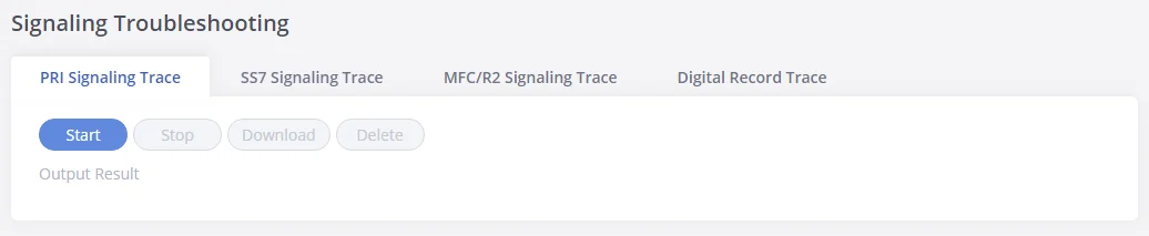
After capturing the trace, users can download it for basic analysis. Or you can contact Grandstream Technical support in the following link for further assistance if the issue is not resolved:
VoIP Trunks
The VoIP trunks allow the GXW450X to be connected over an IP network via SIP protocol to a VoIP provider or to another device that supports the SIP trunks.
VoIP trunks can be configured in GXW450X under Web GUI🡪 Trunks🡪VoIP Trunks. Once created, the VoIP trunks will be listed with Provider Name, Type, Hostname/IP, Username, and Options to edit/detect the trunk.
-
Click on
 to add a new VoIP trunk.
-
Click on
 to configure detailed parameters for the VoIP trunk.
-
Click on
to delete the VoIP trunk.
-
Click on
 to configure DOD.
The VoIP trunk options are listed in the table below.
Type | Select VoIP trunk type to create. Peer SIP Trunk Register SIP Trunk |
Provider Name | Configure a unique label (up to 64 characters) to identify this trunk when listed in outbound rules, inbound rules and etc. |
Host Name | Configure the IP address or URL for the VoIP provider’s server of the trunk. |
NAT | Turn on this setting when the gateway is using public IP and communicating with devices behind NAT. If there is a one-way audio issue, usually it is related to NAT configuration or SIP/RTP port support on the firewall. |
Disable This Trunk | If checked, the trunk will be disabled.
Note: If a current “Register SIP trunk” is disabled, GXW450X will send UNREGISTER message (REGISTER message with expires=0) to the SIP provider. |
TEL URI | If the trunk has an assigned PSTN telephone number, this field should be set to “User=Phone”. Then a “User=Phone” parameter will be attached to the Request-Line and TO header in the SIP request to indicate the E.164 number. If set to “Enable”, “Tel:” will be used instead of “SIP:” in the SIP request. The default setting is disabled. |
From Domain | Configure the actual domain name. This can be used to override the “From” Header. For example, “trunk.GXW450X.provider.com” is the From Domain in From Header: sip: 1234567@trunk.GXW450X.provider.com. |
Transport | Configure the SIP transport protocol to be used in this trunk. UDP; TCP or TLS. The default setting is “UDP” |
If “Type” is set to “Register SIP Trunk” | |
Need Registration | Select whether the trunk needs to register on the external server or not when the “Register SIP Trunk” type is selected. The default setting is “Yes”. |
Allow outgoing calls if registration fails | If enabled outgoing calls even if the registration to this trunk fails will still be able to go through. Note that if we uncheck the “Need Registration” option, this option will be ignored. The default setting is “Yes”. |
Username | Enter the username to register to the trunk from the provider. |
Password | Enter the password to register to the trunk from the provider. |
AuthID | Enter the Authentication ID to register to the trunk from the provider. |
Create New SIP Trunk
After creating the SIP Trunk user can click on
![]() to edit the trunk and have detailed parameters to configure. Below is a table of the Basic and advanced parameters of a SIP trunk.
to edit the trunk and have detailed parameters to configure. Below is a table of the Basic and advanced parameters of a SIP trunk.
Basic Settings | |
Provider Name | Configure a unique label to identify this trunk when listed in outbound rules, inbound rules and etc. |
Host Name | Configure the IP address or URL for the VoIP provider’s server of the trunk. |
Secondary SIP Server | The URL or IP address, and port of the SIP server. This will be used when the primary SIP server fails. |
Keep Original CID | Keep CID from the inbound call when dialing out even if the option “Keep Trunk CID” is enabled. Please make sure the peer GXW at the other end supports matching user entry using the “username” field from the authentication line. |
Keep Trunk CID | Keep trunk CID configured on Basic settings. |
NAT | Turn on this option when the gateway is using public IP and communicating with devices behind NAT. If there is a one-way audio issue, usually it’s related to NAT configuration or SIP/RTP port configuration on the firewall. |
Disable This Trunk | If selected, the trunk will be disabled. |
TEL URI | If the trunk has an assigned PSTN telephone number, this field should be set to “User=Phone”. Then a “User=Phone” parameter will be attached to the Request-Line and TO header in the SIP request to indicate the E.164 number. If set to “Enable”, “Tel:” will be used instead of “SIP:” in the SIP request. The default setting is disabled. |
CallerID Name | Configure the new name of the caller when the extension has no CallerID Name configured. |
From Domain | Configure the actual domain name. This can be used to override the “From” Header. |
Transport | Configure the SIP transport protocol to be used in this trunk.
The default setting is “UDP”. |
Need Registration | Select whether the trunk needs to register on the external server or not when the “Register SIP Trunk” type is selected. The default setting is “Yes”. |
Allow outgoing calls if registration fails | If enabled outgoing calls even if the registration to this trunk fails will still be able to go through. Note that if we uncheck the “Need Registration” option, this option will be ignored. The default setting is “Yes”. |
From User | Configures the actual username of the extension. This can be used to override the “From” Header |
Username | Enter the username to register to the trunk from the provider. |
Password | Enter the password to register to the trunk from the provider. |
AuthID | Enter the Authentication ID to register to the trunk from the provider. |
Advanced Settings | |
Codec Preference | Select the audio codec for the VoIP trunk. The available codecs are: PCMU, PCMA, G.726, G.729, iLBC, G.722, AAL2-G.726-32, G.723, OPUS |
Send PPI Header | If checked, the invite message sent to trunks will contain PPI (P-Preferred-Identity) Header. |
PPI Mode | Configure how to set the PPI number, there are three possible options:
|
Send PAI Header | If checked, the INVITE message sent from the trunk will contain PAI (P-Asserted-Identity) Header. Default is unchecked. |
PAI Header | The user and name of the PAI header. It is formatted as “name |
DOD as From Name | If enabled and “From User” is configured, the INVITE’s From header will contain the DOD number. |
Passthrough PAI Header | If enabled and “Send PAI Header” is disabled, PAI headers will be preserved as calls pass through the GXW450X. |
Outbound Proxy Support | Enable sending an outbound signal to the proxy instead of the devices directly. |
Outbound Proxy | When configured, the outbound signal will be sent to the proxy instead of the devices directly. The outbound proxy can be a domain name or IP address. |
Backup Outbound Proxy | Secondary Outbound Proxy will be used when the primary proxy cannot be connected. |
Remove OBP from Route | If enabled, the Route header will be removed from SIP requests. The default setting is “No”. |
DID Mode | Configure where to get the destination ID of an incoming SIP call, from SIP Request-line or To-header. The default is set to “Request-line”. |
DTMF Mode | Configure the default DTMF mode when sending DTMF on this trunk. |
Enable Heartbeat Detection | If enabled, the GXW450X will regularly send SIP OPTIONS to the device to check if the device is still online. The default setting is “No”. |
Heartbeat Frequency | When the “Enable Heartbeat Detection” option is set to “Yes”, configure the interval (in seconds) of the SIP OPTIONS message sent to the device to check if the device is still online. The default setting is 60 seconds. |
Maximum Number of Call Lines | The maximum number of concurrent calls using the trunk. The default setting 0, which means no limit. |
SRTP | Enable SRTP for the VoIP trunk to use
The default setting is “Disabled”. |
E1/T1/J1 Error Code | Selects the SIP response code to send to the VoIP trunk when the E1/T1/J1 interface is down or unavailable, the avilable values are 480 and 503 , set to 480 by Default
|
VoIP Trunk Configuration Parameters – Register SIP Trunk
Basic Settings | |
Provider Name | Configure a unique label to identify this trunk when listed in outbound rules, inbound rules and etc. |
Host Name | Configure the IP address or URL for the VoIP provider’s server of the trunk. |
Keep Original CID | Keep CID from the inbound call when dialing out even if the option “Keep Trunk CID” is enabled. Please make sure the peer GXW at the other end supports matching user entry using the “username” field from the authentication line. |
Keep Trunk CID | Keep trunk CID configured on Basic settings. |
NAT | Turn on this option when the gateway is using public IP and communicating with devices behind NAT. If there is a one-way audio issue, usually it’s related to NAT configuration or SIP/RTP port configuration on the firewall. |
Disable This Trunk | If selected, the trunk will be disabled. |
TEL URI | If the trunk has an assigned PSTN telephone number, this field should be set to “User=Phone”. Then a “User=Phone” parameter will be attached to the Request-Line and TO header in the SIP request to indicate the E.164 number. If set to “Enable”, “Tel:” will be used instead of “SIP:” in the SIP request. The default setting is disabled. |
Caller ID | Configure the Caller ID. This is the number that the trunk will try to use when making outbound calls. For some providers, it might not be possible to set the CallerID with this option and this option will be ignored. |
CallerID Name | Configure the new name of the caller when the extension has no CallerID Name configured. |
From Domain | Configure the actual domain name. This can be used to override the “From” Header. |
Transport | Configure the SIP transport protocol to be used in this trunk.
The default setting is “UDP”. |
Need Registration | Select whether the trunk needs to register on the external server or not when the “Register SIP Trunk” type is selected. The default setting is “Yes”. |
Allow outgoing calls if registration fails | If enabled outgoing calls even if the registration to this trunk fails will still be able to go through. Note that if we uncheck the “Need Registration” option, this option will be ignored. The default setting is “Yes”. |
From User | Configures the actual username of the extension. This can be used to override the “From” Header |
Username | Enter the username to register to the trunk from the provider. |
Password | Enter the password to register to the trunk from the provider. |
AuthID | Enter the Authentication ID to register to the trunk from the provider. |
Advanced Settings | |
Codec Preference | Select the audio codec for the VoIP trunk. The available codecs are: PCMU, PCMA, G.726, G.729, iLBC, G.722, AAL2-G.726-32, G.723, OPUS |
Send PPI Header | If checked, the invite message sent to trunks will contain PPI (P-Preferred-Identity) Header. |
PPI Mode | Configure how to set the PPI number, there are three possible options:
|
Send PAI Header | If checked, the INVITE message sent from the trunk will contain PAI (P-Asserted-Identity) Header. Default is unchecked. |
PAI Header | The user and name of the PAI header. It is formatted as “name |
DOD as From Name | If enabled and “From User” is configured, the INVITE’s From header will contain the DOD number. |
Passthrough PAI Header | If enabled and “Send PAI Header” is disabled, PAI headers will be preserved as calls pass through the GXW450X. |
Outbound Proxy Support | Enable sending an outbound signal to the proxy instead of the devices directly. |
Outbound Proxy | When configured, the outbound signal will be sent to the proxy instead of the devices directly. The outbound proxy can be a domain name or IP address. |
Backup Outbound Proxy | Secondary Outbound Proxy will be used when the primary proxy cannot be connected. |
Remove OBP from Route | If enabled, the Route header will be removed from SIP requests. The default setting is “No”. |
DID Mode | Configure where to get the destination ID of an incoming SIP call, from SIP Request-line or To-header. The default is set to “Request-line”. |
DTMF Mode | Configure the default DTMF mode when sending DTMF on this trunk. |
Enable Heartbeat Detection | If enabled, the GXW450X will regularly send SIP OPTIONS to the device to check if the device is still online. The default setting is “No”. |
Heartbeat Frequency | When the “Enable Heartbeat Detection” option is set to “Yes”, configure the interval (in seconds) of the SIP OPTIONS message sent to the device to check if the device is still online. The default setting is 60 seconds. |
Maximum Number of Call Lines | The maximum number of concurrent calls using the trunk. The default setting 0, which means no limit. |
SRTP | Enable SRTP for the VoIP trunk to use
The default setting is “Disabled”. |
E1/T1/J1 Error Code | Selects the SIP response code to send to the VoIP trunk when the E1/T1/J1 interface is down or unavailable, the avilable values are 480 and 503 , set to 480 by Default
|
VoIP Trunk Configuration Parameters – Peer SIP Trunk
Direct Outward Dialing (DOD)
The GXW450X provides Direct Outward Dialing (DOD) for both Digital and SIP trunks, which is a service of a local phone company (or local exchange carrier) that allows subscribers to connect to outside lines directly.
Example of how DOD is used:
Company ABC has a SIP trunk. This SIP trunk has 4 DIDs associated with it. The main number of the office is routed to an auto attendant. The other three numbers are direct lines to specific users of the company. Now when a user makes an outbound call their caller ID shows up as the main office number. This poses a problem as the CEO would like his calls to come from their direct line. This can be accomplished by configuring DOD for the CEO’s number/extension.
Steps to configure DOD on the GXW4500:
1. To set up DOD go to GXW450X Web GUI→Trunk→VoIP Trunks/Digital trunk page.
2. Click to access the DOD options for the selected SIP Trunk.
3. Click “Create a new DOD” to begin your DOD setup
4. For “DOD Number” enter one of the numbers (DIDs) from your SIP/Digital trunk provider. In the example above
Company ABC received 4 DIDs from their provider. ABC will enter the number for the CEO’s direct line.
5. Set the DOD name and If the extension number needs to be appended to the DID number click on “Add Extension”.
6. Enter a number in the “Number” field. Users have the option of entering more than one number/extension separating them using “,”. In this case, Company ABC would enter the CEO’s numbers/extensions.
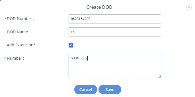
7. Click “Save” at the bottom.
Once completed, the user will return to the EDIT DOD page which shows all the extensions that are associated with a particular DOD.
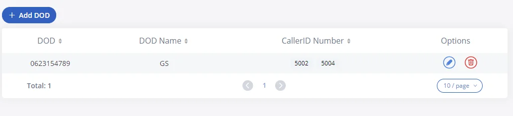
Exporting DODs:
To export the list of DODs created, under Trunks => VoIP Trunks => DOD , click the icon ![]() , this will export all created DODs with their corresponding DOD name and Caller ID number, to a csv file
, this will export all created DODs with their corresponding DOD name and Caller ID number, to a csv file
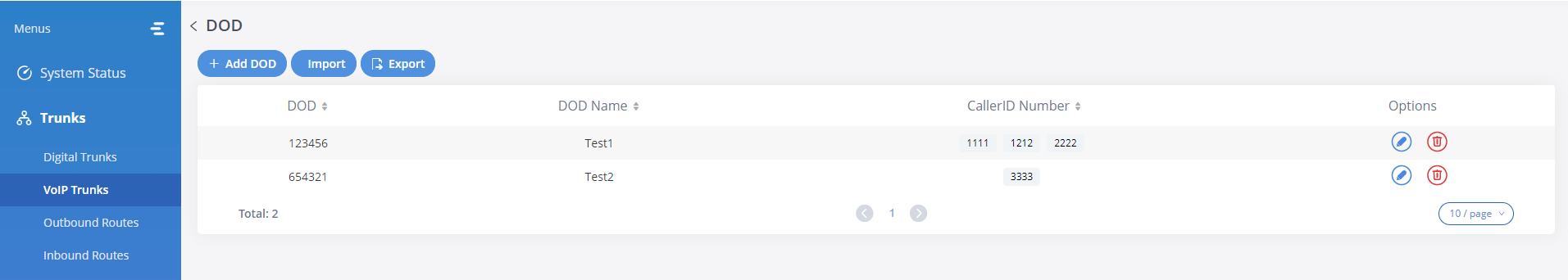
Importing DODs:
You can imprt DOD numbers to the GXW450x gateway, by clicking the icon, ![]()
After this you will be prompted to upload a CSV file, containg the DOD numbers, and other additional information if needed,
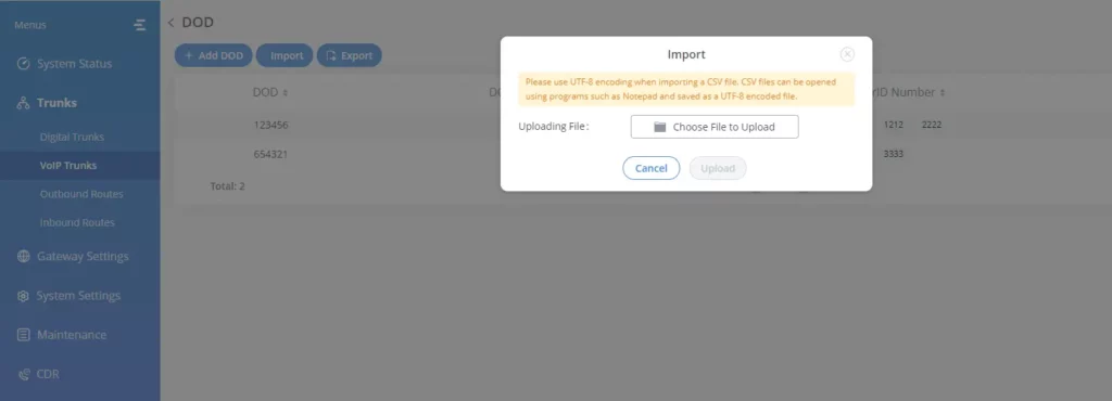
Outbound Routes
An outbound route is a set of rules defined by privileges and patterns that the gateway uses to decide the numbers that can go out through the trunk, and who has the right to use the trunk and trunk to use for an outbound call.
To create an outbound route, Go to Web GUI🡪 Trunks🡪Outbound Routes.
-
Click on
 to add a new outbound route.
-
Click on
to edit the outbound route.
-
Click on
to delete the outbound route.
On the GXW450X, the outbound route priority is based on the “Best matching pattern”. For example, the GXW450X has outbound route A with pattern 1xxx and outbound route B with pattern 10xx configured. When dialing 1000 for an outbound call, outbound route B will always be used first. This is because pattern 10xx is a better match than pattern 1xxx. Only when there are multiple outbound routes with the same pattern configured, the GXW450X will use the first pattern matched.
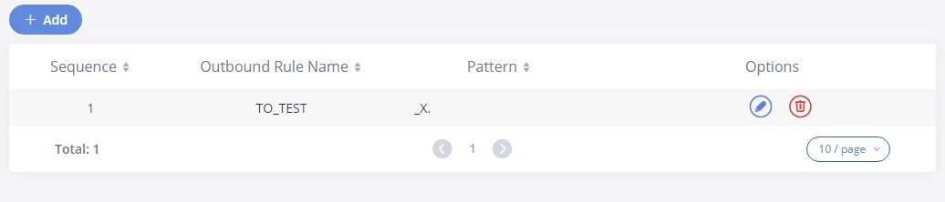
Calling Rule Name | Configure the name of the calling rule (e.g., local, long-distance, etc). Letters, digits, _, and – are allowed. |
Pattern | All patterns are prefixed with the “_”. Special characters: X: Any Digit from 0-9. Z: Any Digit from 1-9.
N: Any Digit from 2-9. “.“: Wildcard. Match one or more characters. “!“: Wildcard. Match zero or more characters immediately. Example: [12345–9] – Any digit from 1 to 9.
Notes:
Multiple patterns can be used. Each pattern should be entered in new line. Example:
_X.
_NNXXNXXXXX
_818X. |
Enable Filter on Source Caller ID | When enabled, users could specify extensions allowed to use this outbound route. “Privilege Level” is automatically disabled if using “Enable Filter on Source Caller ID”.
The following two methods can be used at the same time to define the extensions as the source caller ID. 1. Select available extensions/extension groups from the left to the right. This allows users to specify arbitrary single extensions available in the PBX. 2. Custom Dynamic Route: define the pattern for the source caller ID. This allows users to define extension range instead of selecting them one by one.
|
Main Trunk | |
Trunk | Select the trunk for this outbound rule. |
Strip | Allows the user to specify the number of digits that will be stripped from the beginning of the dialed string before the call is placed via the selected trunk.
Example:
The users will dial 9 as the first digit of long-distance calls. However, 9 should not be sent out via digital lines and the PSTN line. In this case, 1 digit should be stripped before the call is placed. |
Prepend | Specify the digits to be prepended before the call is placed via the trunk. Those digits will be prepended after the dialing number is stripped. |
Failover Trunk | |
Trunk | Failover trunks can be used to make sure that a call goes through an alternate route when the primary trunk is busy or down. If “Use Failover Trunk” is enabled and “Failover trunk” is defined, the calls that cannot be placed via the regular trunk may have a secondary trunk to go through.
GXW450X supports up to 10 failover trunks.
Example: The user’s primary trunk is a VoIP trunk and the user would like to use the PSTN when the VoIP trunk is not available. The PSTN trunk can be configured as the failover trunk of the VoIP trunk. |
Strip | Allows the user to specify the number of digits that will be stripped from the beginning of the dialed string before the call is placed via the selected trunk. Example: The users will dial 9 as the first digit of long-distance calls. However, 9 should not be sent out via digital lines and the PSTN line. In this case, 1 digit should be stripped before the call is placed. |
Prepend | Specify the digits to be prepended before the call is placed via the trunk. Those digits will be prepended after the dialing number is stripped. |
Time Condition | |
Time Condition Mode | Use Main Trunk or Failover Trunk: Use the Main Trunk and its settings during the configured time conditions. If the main trunk is unavailable, the Failover Trunk and its settings will be used instead. Use Specific Trunks: Use specific trunks during the configured time conditions. The Strip and Prepend settings of the Main Trunk will be used. If a trunk is unavailable during its time condition, no failover trunks will be used. |
Time Condition | Users could customize holiday time, office time, or a specified time to allow the outbound route to be used. |
Outbound Route
Inbound Routes
When a call comes into the GXW450X from the outside, it will usually arrive along with information about the telephone number that was dialed (also known as the “DID”) and the Caller ID of the person who called.
The Inbound Routes are used to tell the system what to do with calls that come into the GXW450X on any trunk based on the pattern of the DID and the caller ID of the person who called.
Inbound routes can be configured via Web GUI🡪 Trunks🡪Inbound Routes.
-
Click on
button to add a new inbound route.
-
Click on
 To import inbound routes.
-
Click on
 to export inbound routes.
-
Click on
to edit the inbound route.
-
Click on
to delete the inbound route
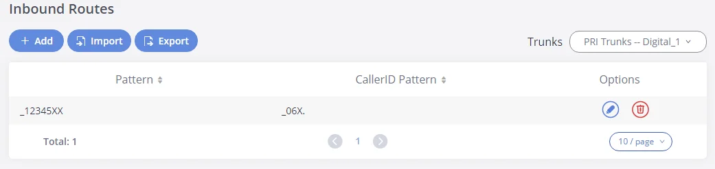
Inbound Route Configuration
Trunks | Select the trunk to configure the inbound rule. |
Pattern | Defines the Call Pattern. |
CallerID Pattern | Defines the CallerID Pattern. All patterns are prefixed by "_" character, but please do not enter more than one "_" at the beginning. All patterns can add comments, such as "_pattern /* comment */". In patterns, some characters have special meanings: |
Set CallerID Info | Manipulate Caller ID (CID) name and/or number within the call flow to help identify who is calling. |
Inbound Rule Configuration Parameters
Inbound Route: Import/Export Inbound Route
Users can import and export inbound routes to quickly set up inbound routing on a GXW450X or to back up an existing configuration. An exported inbound route configuration can be directly imported without needing any manual modifications.

The imported file should be in CSV format and using UTF-8 encoding, the imported file should contain the below columns, and each column should be separated by a comma (It is recommended to use Notepad++ for the imported file creation):
- Pattern: Always prefixed with _
- CallerID Pattern: Always prefixed with _
GATEWAY SETTINGS
This section describes internal options that haven’t been mentioned in previous sections yet. The settings in this section can be applied globally to the GXW450X, including general configurations, jitter buffer, RTP settings, and hardware config. The options can be accessed via Web GUI🡪Gateway Settings🡪General Settings.
SIP Settings
The GXW450X SIP global settings can be accessed via Web GUI🡪 Gateway Settings🡪SIP Settings.
General SIP Settings
On this page, users can define the Binding UDP Port for SIP protocol and Enable 486 to Failover Trunk.
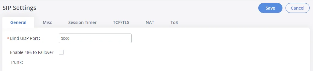
Bind UDP Port | Configure binding UDP port for SIP. The default setting is “5060”. |
Enable 486 to Failover Trunk | Reroutes failed outbound calls that receive a 486 response through the failover trunk to retry the call. If disabled, calls that receive a 486 response will be terminated. The default setting is “unchecked”. |
Enable 600 to Failover Trunk | Reroutes failed outbound calls that receive a 600 response through the failover trunk to retry the call. If disabled, calls that receive a 600 response will be terminated. |
BroadSoft Mode | Enables BroadSoft Mode, to make the gateway comptaible with the broadsoft telephny features. |
Enable Diversion Header | allows users to enable or disable the Diversion header, which is used in SIP calls to indicate call forwarding information. |
SIP Settings – General
Misc
On this Web page, users can define the DNS mode used by the GXW450X and Outbound SIP Registrations.
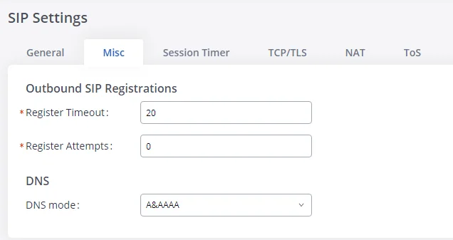
Outbound SIP Registrations | |
Register Timeout | Configures the register retry timeout (in seconds). The default setting is 20. |
Register Attempts | Configure the number of registration attempts before giving up. 0 means continuously trying until the registration request is accepted. The default setting is “0”. |
DNS | |
DNS mode | Selects DNS mode. Available options:
A&AAAA A AAAA
The default setting is “A&AAAA”
Note: This setting only affects the DNS queries that occur when making calls. |
SIP Settings – Misc
Session Timer
Force Timer | If checked, always request and run the session timer. The default is “unchecked”. |
Timer | If checked, run the session timer only when requested by another UA. Default is “checked”. |
Session Expire | Configure the maximum session refresh interval (in seconds). The default setting is 1800. |
Min SE | Configure the minimum session refresh interval (in seconds). The default setting is 90. |
SIP Settings/Session Timer
TCP and TLS
TCP Enable | Configure to allow incoming TCP connections with the GXW450X. The default setting is “No”. |
TCP Bind IPv4 Address | Configure the IP address for the TCP server to bind to. 0.0.0.0 means binding to all interfaces. The port number is optional. If not specified, 5060 will be used. The default setting is “0.0.0.0:5060” |
TCP Bind IPv6 Address | Configure the IPv6 address for the TCP server to bind to. “[::]” means bind to all interfaces. The port number is optional with the default being 5060. For example, [2001:0DB8:0000:0000:0000:0000:1428:0000]:5060. The default setting is “[::]:5060”. |
TLS Enable | Configure to allow incoming TLS connections with the GXW450X. The default setting is “No”. |
TLS Bind IPv4 Address | Configure the IP address for the TLS server to bind to. 0.0.0.0 means binding to all interfaces. The port number is optional. If not specified, 5061 will be used. The default setting is “0.0.0.0:5061”.
Note: The IP address must match the common name (hostname) in the certificate. Please do not bind a TLS socket to multiple IP addresses. For details on how to construct a certificate for SIP, please refer to the following document: http://tools.ietf.org/html/draft-ietf-sip-domain-certs |
TLS Bind IPv6 Address | Configure the IPv6 address for the TLS server to bind to. “[::]” means bind to all interfaces. The port number is optional with the default being 5061. For example, [2001:0DB8:0000:0000:0000:0000:1428:0000]:5061. Note: The IP address must match the common name (hostname) in the certificate so that the TLS socket won’t bind to multiple IP addresses. The default setting is “[::]:5061”. |
TLS Do Not Verify | If enabled, the TLS server’s certificate won’t be verified when acting as a client. The default setting is “Yes”. |
TLS Self-Signed CA | This is the CA certificate if the TLS server being connected to requires a self-signed certificate, including the server’s public key. This file will be renamed as “TLS.ca” automatically. Note: The size of the uploaded “ca” file must be under 2MB. |
TLS Cert | This is the Certificate file (*.pem format only) used for TLS connections. It contains a private key for the client and a signed certificate for the server. This file will be renamed as “TLS.pem” automatically. Note: The size of the uploaded certificate file must be under 2MB. |
TLS Key | The size of a private key must be under 2MB. This is the private key (*.key format only) for TLS connections. This file will be renamed as “TLS.key” automatically. |
TLS CA Cert | This file must be named with the CA subject name hash value. It contains CA’s (Certificate Authority) public key, which is used to verify the accessed servers.
Note:
The size of the uploaded CA certificate file must be under 2MB. |
TLS CA List | Display a list of files under the CA Cert directory. |
SIP Settings/TCP and TLS
NAT
External Host | Configure a static IP address and port (optional) used in outbound SIP messages if the GXW450X is behind NAT. If it is a hostname, it will only be looked up once. |
Use IP address in SDP | If enabled, the SDP connection will use the IP address resolved from the external host. The default setting is “enabled”. |
External UDP Port | Configure the externally mapped UDP port when the GXW450X is behind a static NAT or PAT. The default setting is “5060”. |
External TCP Port | Configure the externally mapped TCP port when the GXW450X is behind a static NAT or PAT. The default setting is “5060”. |
External TLS Port | Configures the externally mapped TLS port when GXW450X is behind a static NAT or PAT. The default setting is “5061”. |
Local Network Address | Adds a list of network addresses that are considered inside of the NAT network. Multiple entries are allowed. If not configured, the external IP address will not be set correctly. A sample configuration could be as follows: 192.168.0.0/16 |
NAT Settings
ToS
ToS For SIP | Configure the Type of Service for SIP packets. The default setting is None. |
ToS For RTP Audio | Configure the Type of Service for RTP audio packets. The default setting is None. |
Send Compact SIP Headers | If enabled, compact SIP headers will be sent. The default setting is “No”. Note: This change requires a system reboot to take effect. |
Enable Relaxed DTMF | Select to enable relaxed DTMF handling. The default setting is “No”. |
DTMF Mode | Configures the default mode for sending DTMF. RFC2833: DTMF is transmitted as audio in the RTP stream but is encoded separately from the audio stream. Inband: DTMF is transmitted as audio and is included in the audio stream. Requires alaw/ulaw codecs. SIP INFO: DTMF is transmitted through a separate network connection from the media streams. Auto: DTMF mode will be negotiated with the remote peer. RFC2833 will be used by default unless the remote peer does not support it.
The default setting is “RFC2833”. |
RTP Timeout | Configure the timeout in seconds. When the call is in talking status, if there is no RTP activity after the timeout, the call will be terminated. The default setting is 90 seconds. |
RTP Hold Timeout | Configure the timeout in seconds. When the call is on hold, if there is no RTP activity after the timeout, the call will be terminated. This value must be larger than “RTP Timeout”. The default setting is 100 seconds. |
RTP Keep-alive | Configure the interval (in seconds) that an RTP Keepalive packet will be sent on an SDP connection. The default setting is 0 (no RTP Keepalive).
|
Default Incoming/Outgoing Registration Time | Configure the default duration (in seconds) of incoming/outgoing registration. The default setting is 120. |
100rel | Configure the 100rel setting on GXW450X.
No: Unsupported. Yes: Supported. Required: Forced to support.
The default setting is “Yes”. |
Trust Remote Party ID | Configure whether the Remote-Party ID should be trusted. The default setting is “No”. |
Send Remote Party ID | Configure whether the Remote-Party ID should be sent or not. The default setting is “No”. |
Generate In-Band Ringing | Configure whether the GXW450X should generate inband ringing or not.
Yes: The GXW450X will send 180 Ringing followed by 183 Session Progress and in-band audio. No: The GXW450X will send 180 Ringing if 183 Session Progress has not been sent yet. If the audio path is established already with 183 then send in-band ringing. Never: Whenever ringing occurs, the GXW450X will send 180 Ringing as long as 200OK has not been set yet.
The default setting is “Never”. |
Server User Agent | Configure the user agent string for the GXW450X. |
Default Incoming/Outgoing Registration Time | Configure the default duration (in seconds) of incoming and outgoing registration. The default setting is 120 seconds. |
ToS Settings
RTP Setting
RTP Settings
RTP Start | Configure the RTP port starting number. The default setting is 10000. |
RTP End | Configure the RTP port ending address. The default setting is 20000. |
Strict RTP | Configure to enable or disable strict RTP protection. If enabled, RTP packets that do not come from the source of the RTP stream will be dropped. The default setting is “Disable”. |
RTP Checksums | Configure to enable or disable RTP Checksums on RTP traffic. The default setting is “Disable”. |
RTP Settings
Payload Type Settings
The GXW450X payload type for audio codecs can be configured here.
AAL2-G.726 | Configure payload type for ADPCM (G.726, 32kbps, AAL2 codeword packing). The valid range is between 96 and 127. The default setting is 112. |
DTMF | Configure payload type for DTMF. The valid range is between 96 and 127. The default setting is 101. |
G.721 Compatible | Configure to enable/disable G.721 compatible. The default setting is Yes. |
G.726 | Configure the payload type for G.726 if “G.721 Compatible” is disabled. The default setting is 111. |
iLBC | Configure the payload type for iLBC. The valid range is between 96 and 127. The default setting is 97. |
OPUS | Configure the payload type for OPUS. The valid range is between 96 and 127. The default setting is 123. |
Payload Type Settings
-
Click on
 to set the values of the payload parameters to the factory default values
-
While configuring the payload values users can Click on
 to reset the values to the last saved values on the gateway.
Voice Prompt
The GXW450X supports multiple languages in Web GUI as well as system voice prompt. The following languages are currently supported in the system voice prompt:
English (United States), British English, Arabic, Chinese, Dutch, French, German, Greek, Hebrew, Italian, Polish, Portuguese, Russian, Spanish, Catalan, Swedish, Czech, and Turkish.
English (United States) and Chinese voice prompts are built-in with the GXW450X already. The other languages provided by Grandstream can be downloaded and installed from the GXW450X Web GUI directly. Additionally, users could customize their own voice prompts, package them and upload them to the GXW450X.
Language settings for voice prompts can be accessed under Web GUI🡪Gateway Settings🡪Voice Prompt🡪Language.
Download and Install Voice Prompt Package
To download and install voice prompt package in different languages from GXW450X Web GUI, click on
![]() button.
button.
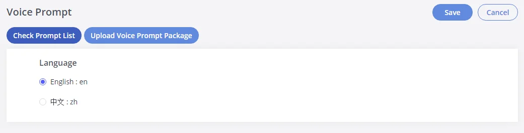
A new dialog window of the voice prompt package list will be displayed. Users can see the version number (latest version available V.S. current installed version), package size, and options to upgrade or download the language
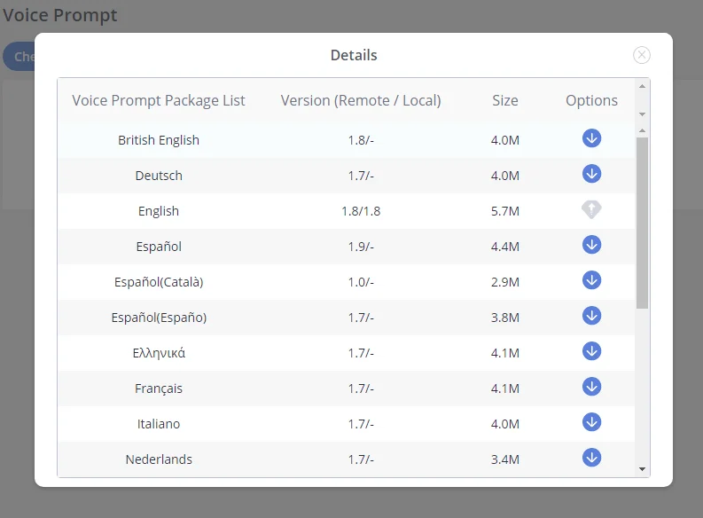
Click on
![]() to download the language to the GXW450X. The installation will be automatically started once the downloading is finished.
to download the language to the GXW450X. The installation will be automatically started once the downloading is finished.
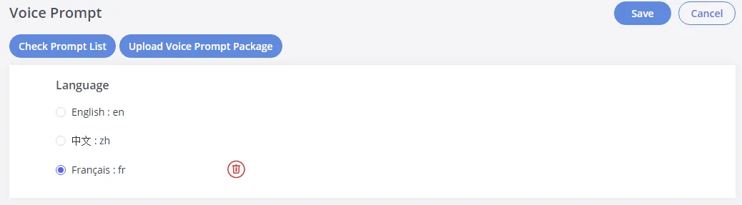
A new language option will be displayed after successfully installed. Users then could select it to apply in the GXW450X system voice prompt or delete it from the GXW450X
Manual Upload of Prompt Package
Users can upload the prompt package manually to the GXW450X. Users can create their own prompt package for different languages and use them as the default voice prompts.
To upload the voice prompt to the GXW450X, press the
![]() button and brows the prompt package.
button and brows the prompt package.

Call Failure Tone Settings
SIP Trunk Prompt Tone
Prompt Tone Settings tab has been added to the GXW to help users choose which prompt will be played by the GXW during call failure, the following voice message responses have been added and can be set to be played for 4XX, 5XX, and 6XX call failures:
- The default for 404 and 604 status codes: “Your call can’t be completed as dialed. Please check the number and dial again.”
- The default for 5xx status codes: “Server error. Please check your device.”
- The default for 403 and 603 status codes: “The call was rejected by the server. Please try again later.”
- The default for all other status codes: “All circuits are busy now. Please try again later.”
Additionally, custom voice messages recorded and uploaded in Gateway Settings🡪Voice Prompt🡪Custom Prompt can be used for these failure responses instead of the default messages.
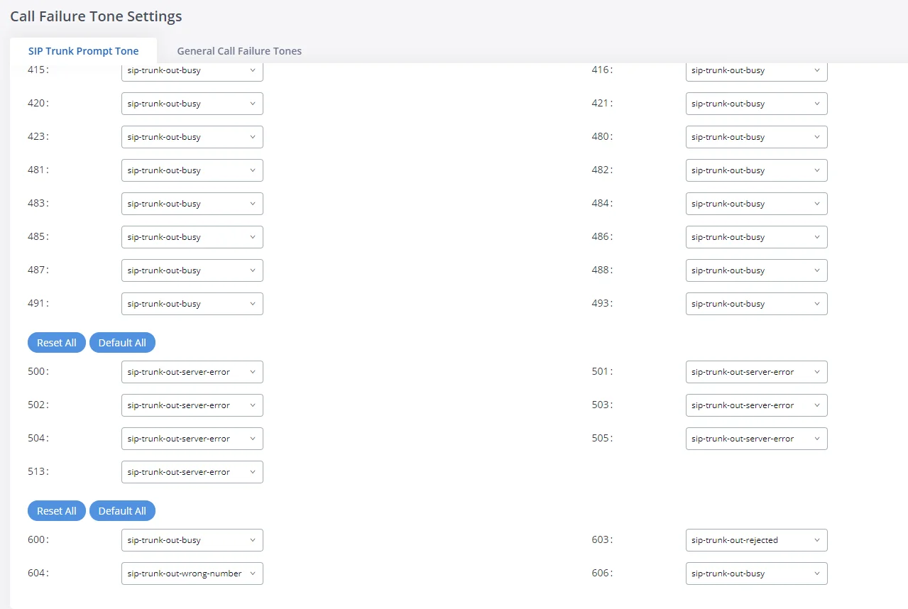
General Call Failure Tone
Moreover, users also have the possibility to customize the prompt for typical call failure reasons like (no permission to allow outbound calls, busy lines, incorrect number dialed …etc.).
To customize these prompts users could record and upload their own files under “Gateway Settings 🡪 Voice Prompt 🡪 Custom Prompts” then select each one for a specific call failure case under the “Gateway Settings🡪 Call Failure Tone Settings 🡪 General Call Failure Tones” page as shown on the following figure:
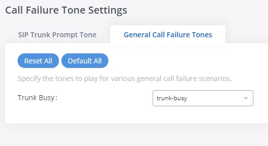
Jitter Buffer
A jitter buffer is used at the receiving equipment to store incoming RTP packets, re-align them in terms of timing and check they are in the correct order. If some arrive slightly out of sequence then, provided it is large enough, the jitter buffer can put them back into the right sequence. However, for this to work the receiving device must delay the audio very slightly while it checks and reassembles the packet stream.
Below are the Jitter buffer Settings to control the size of the buffer and its implementation mode:
Enable Jitter Buffer | Select to enable the jitter buffer on the sending side of the SIP channel. The default setting is “No”. |
Jitter Buffer Size | Configure the time (in ms) to buffer. This is the jitter buffer size used in the “Fixed” jitter buffer or used as the initial time for the “adaptive” jitter buffer. The default setting is 100. |
Implementation | Configure the jitter buffer implementation on the sending side of a SIP channel. The default setting is “Fixed”.
|
Max Jitter Buffer | Configure the maximum time (in ms) to buffer for “Adaptive” jitter buffer implementation or used it as the jitter buffer size for “Fixed” jitter buffer implementation. The default setting is 100. |
Jitter Buffer Settings
Interface Settings
The GXW450X supports E1/T1/J1 which are physical connection technologies used in digital networks. T1 is the North American standard, J1 is used in Japan, whereas E1 is the European standard. GXW450X supports four signaling protocols: PRI_NET, PRI_CPE, MFC/R2, and SS7. PRI provides a varying number of channels depending on the standards in the country of implementation (E1, T1, or J1); MFC/R2 is a signaling protocol heavily used over E1 trunks; SS7 uses out-of-band signaling, which travels on a separate, dedicated channel rather than within the same channel as the telephone call, providing more efficiency and higher security level when the telephone calls are set up.
The interface settings page allows the configuration of digital hardware parameters. For more details, refer to the [Digital Hardware Configuration] section.
GXW450X also allows the users to configure Tone Region by choosing their country to set the default tones for dial tone, busy tone, and ring tone…to be sent. If not specified, the default setting is “The United States”.
MAINTENANCE
The Maintenance section lists different tools to help troubleshoot the issues that might be encountered while using the GXW450X alongside a set of options to manage users, control web GUI access, upgrade the firmware, backup the configuration, take ethernet and Digital traces …etc.
User Management
User management is on the Web GUI🡪 Maintenance🡪User Management page. Users could create multiple accounts for different administrators to log in to the GXW450X Web GUI.
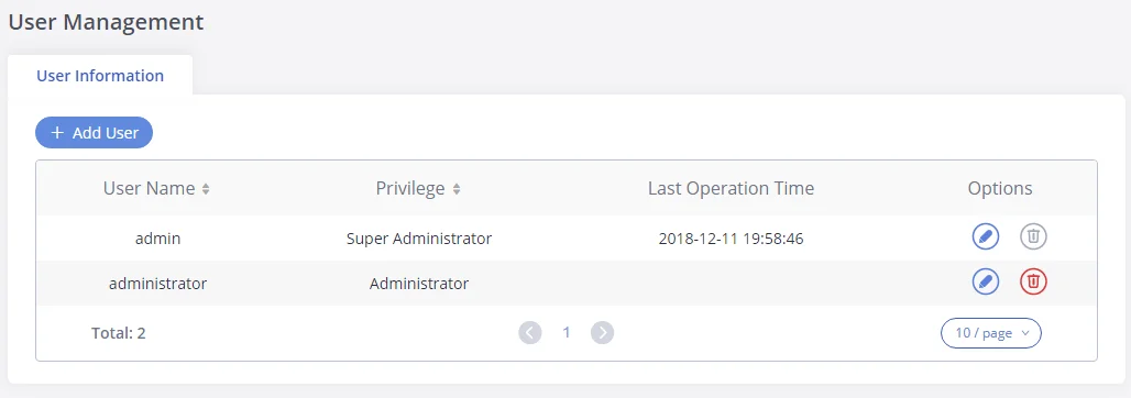
-
Click on
 To add a user
-
Click on
 to edit the user
-
Click on
 to delete the user
When logged in as Super Admin, click on
![]() to create a new account for Web GUI user. The following dialog will prompt. Configure the parameters as shown in below table.
to create a new account for Web GUI user. The following dialog will prompt. Configure the parameters as shown in below table.
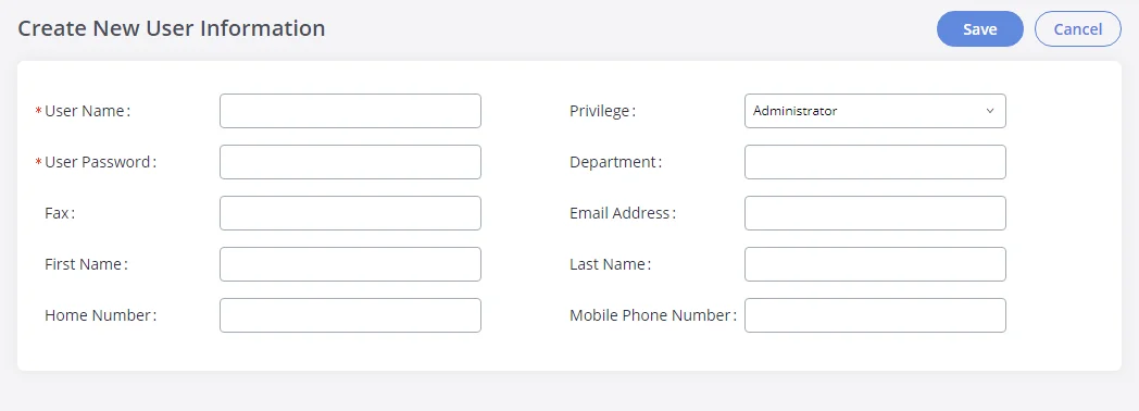
User Name | Configures a username to identify the user which will be required in Web
GUI login. Letters, digits, and underscores are allowed in the user
name. |
Privilege | This is the role of the Web GUI user. Currently, only “Admin” is supported when Super Admin creates a new user. |
User Password | Configures a password for this user which will be required in Web GUI login. Letters, digits, and underscores are allowed. |
Department | Enters the necessary information to keep a record for this user.
|
Fax | Defines the Fax Number |
Email Address | Defines the Email Address |
First Name | Defines the First Name |
Last Name | Defines the Last Name |
Home Number | Defines the Home Number |
Mobile Phone Number | Defines the Phone Number |
Create New User Information
Change Information
Change Password
Follow the steps below to change the Web GUI access password.
- Go to the Web GUI🡪Maintenance🡪Change Information page.
- Enter the old password first.
- Enter the new password and retype the new password to confirm. The new password has to be at least 4 characters. The maximum length of the password is 16 characters.
- Configure the Email Address that is used when login credentials are lost.
- Click on “Save” and the user will be automatically logged out.
- Once the web page comes back to the login page again, enter the username “admin” and the new password to login.
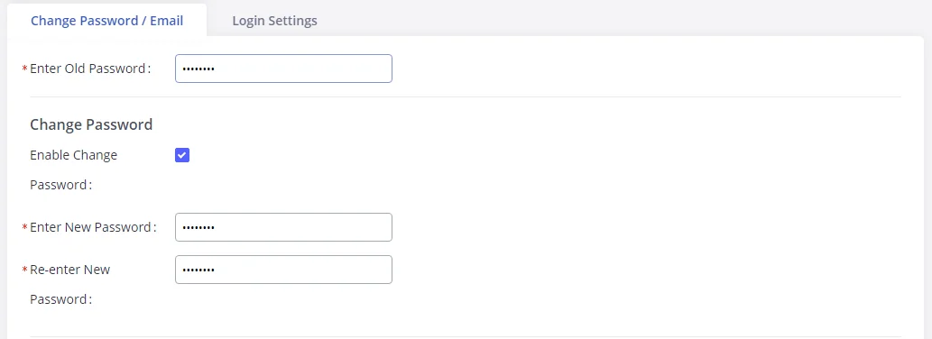
Enter Old Password | Enter the old Password for GXW450X |
Enable Change Password | When enabled, the fields to enter the new password will be displayed |
Enter New Password | Enter the New Password for GXW450X |
Re-enter New Password | Retype the New Password for GXW450X |
Change Password Parameters
Change Binding Email
GXW450X allows users to configure binding email in case log in password is lost. GXW450X login credentials will be sent to the designated email address. The feature can be found under Web GUI🡪Maintenance🡪Change Information🡪Change Binding Email.

Login Settings
After the user logs in to the GXW450X Web GUI, the user will be automatically logged out after a certain timeout, or he/she can be banned for a specific period if the login timeout is exceeded. Those values can be specified under the GXW450X web GUI🡪Maintenance🡪Change Information🡪Login Settings page.
The “User Login Timeout” value is in minutes and the default setting is 10 minutes. If the user doesn’t make any operation on Web GUI within the timeout, the user will be logged out automatically. After that, the Web GUI will be redirected to the login page and the user will need to enter the username and password to log in.
If set to 0, there is no timeout for the Web GUI login session and the user will not be automatically logged out.
The “maximum number of login attempts” can prevent the GXW450X from brute force decryption, if this number is exceeded user IP address will be banned from accessing the GXW for a period based on user configuration, the default value is 5.
“User ban period” specifies the period in minutes an IP will be banned from accessing the GXW if the User max number of try login is exceeded, the default value is 5.
“Login Banned User List” shows the list of IPs banned from the GXW.
“Login White List” Users can add a list of IPs’ to avoid the above restriction, thus, they can exceed the User’s max number of try login.
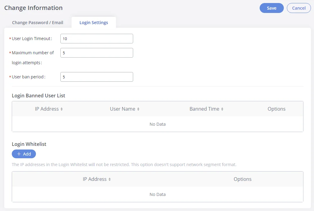
Operation Log
The admin has the authority to view operation logs on the GXW450X Web GUI🡪Maintenance🡪 Operation Log page. Operation logs list the operations done by all the Web GUI users, for example, Web GUI login, creating trunk, creating outbound rule, etc. There are 7 columns to record the operation details “Date”, “User Name”, “IP Address”, “Results”, “Page Operation”, “Specific Operation” and “Remark”.
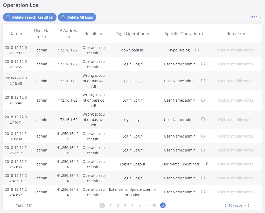
The operation log can be sorted and filtered for easy access. Click on the header of each column to sort. For example, clicking on “Date” will sort the logs according to the operation date and time. Clicking on “Date” again will reverse the order.
Date | The date and time when the operation is executed. |
User Name | The username of the user who performed the operation. |
IP Address | The IP address from which the operation is made. |
Results | The result of the operation. |
Page Operation | The page where the operation is made. For example, login, logout, delete user, create trunk and etc. |
Specific Operation | Click on "info icon" to view the options and values configured by this operation. |
Remark | |
Operation Logs
Users could also filter the operation logs by time condition, IP address and/or username. To use the filter, click on
![]() and configure the conditions then click on
and configure the conditions then click on
![]() .
.
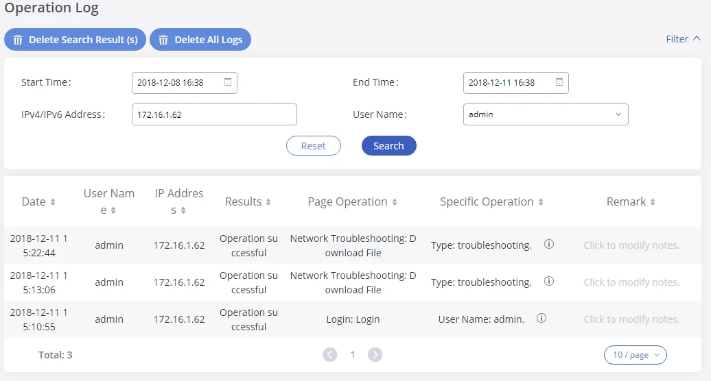
The above figure shows an example that operations made by user “admin” on a device with IP 172.16.1.62 from 2018-12-08 16:38 to 2018-12-11 16:38 are filtered out and displayed.
To delete operation logs, users can perform filtering first and then click on
![]() to delete the filtered result of operation logs. Or users can click on
to delete the filtered result of operation logs. Or users can click on
![]() to delete all operation logs at once.
to delete all operation logs at once.
Syslog
On the GXW450X, users could dump the Syslog information to a remote server under Web GUI🡪Maintenance🡪Syslog. Enter the Syslog server hostname or IP address and select the module/level for the Syslog information.
The default Syslog level for all modules is “error”, which is recommended in your GXW450X settings because it can be helpful to locate the issues when errors happen.
Some typical modules for GXW450X functions are as follows and users can turn on “notice” and “verb” levels besides the “error” level.
- pbx: This module is related to general PBX functions.
- pjsip: This module is related to SIP calls.
- chan_dahdi: This module is related to digital calls (E1/T1/J1).
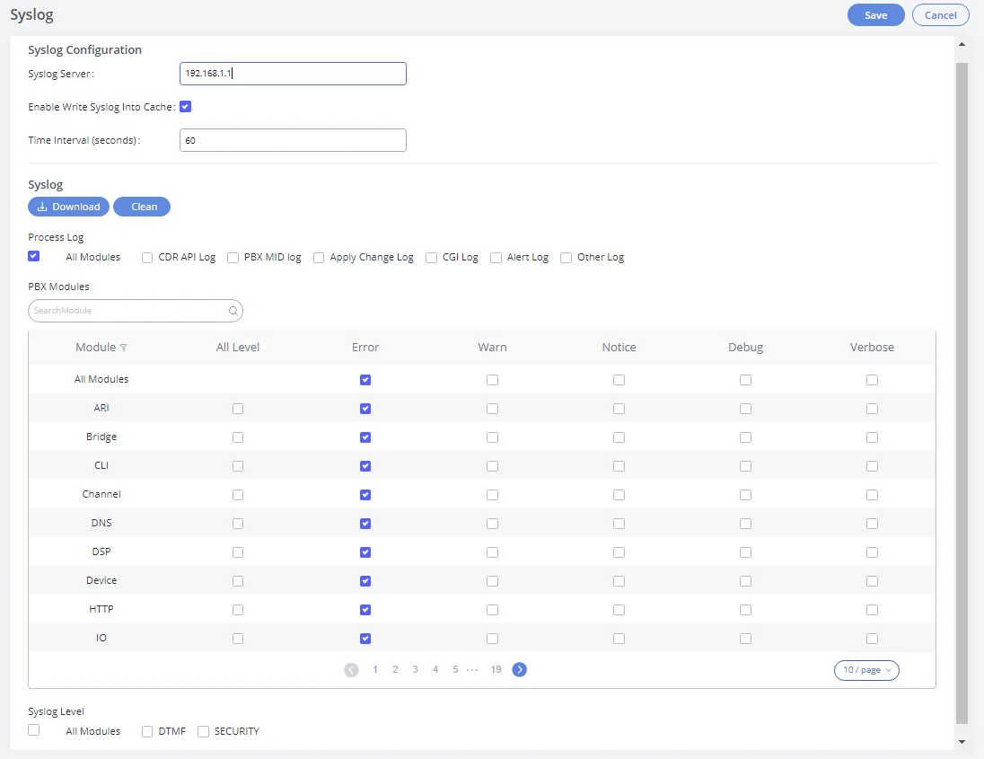
The reserved size for Syslog entries on the cache memory of the GXW is 50M, once this size is reached the GXW will clean up 2M of the oldest Syslog entries to allow to save new logs.
System Events
The GXW450X can monitor important system events, log the alerts and send Email notifications to the system administrator.
Alert Log
Under Web GUI🡪Maintenance🡪System Events🡪Alert Log, system messages are listed when the alert is triggered for the configured system events. The following picture shows the “User Login Successes”, “User Login Failed” and “System Reboot” alert logs.
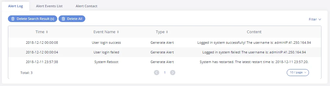
Users could also filter the Alert Logs by time condition, Event Name, and/or Type. To use the filter, click on ![]() and configure the conditions then click on
and configure the conditions then click on ![]() .
.
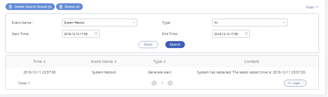
The above figure shows an example of a System reboot Alerts logged on 2018-12-11 at 23:57 displayed using the filter Event name System Reboot.
To delete alert logs, users can perform filtering first and then click on
![]() to delete the filtered result of operation logs. Or users can click on
to delete the filtered result of operation logs. Or users can click on
![]() to delete all alert logs at once.
to delete all alert logs at once.
Alert Events List
The system alert events list can be found under Web GUI🡪Maintenance🡪System Events🡪Alert Events. The following event is currently supported on the GXW450X which will have an alert, and/or an Email generated if occurred:
- Disk Usage
- Modify Super Admin Password
- Memory Usage
- System Reboot
- System Update
- System Crash
- Register SIP trunk failed
- Restore Config
- User Login Success
- User Login Failed
- SIP Outgoing Call through Trunk Failure
- Fail2ban Blocking
- SIP Peer Trunk Status
- User Login Banned
- External Disk Usage
- The CDR database is corrupted
Click on
![]() to configure the parameters for each event
to configure the parameters for each event
- Disk Usage
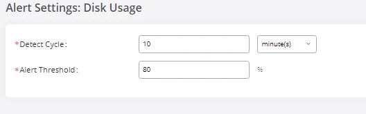
- Detect Cycle: The GXW450X will perform the internal disk usage detection based on this cycle. Users can enter the number and then select second(s)/minute(s)/hour(s)/day(s) to configure the cycle.
- Alert Threshold: If the detected value exceeds the threshold (in percentage), the GXW450X system will send the alert.
- External Disk Usage
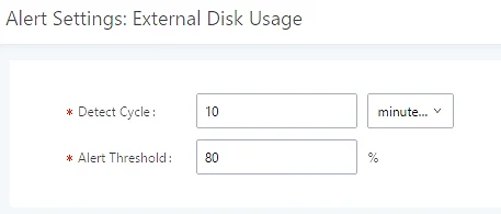
- Detect Cycle: The GXW450X will perform the External disk usage detection based on this cycle. Users can enter the number and then select second(s)/minute(s)/hour(s)/day(s) to configure the cycle.
- Alert Threshold: If the detected value exceeds the threshold (in percentage), the GXW450X system will send the alert.
- Memory Usage
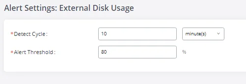
- Detect Cycle: The GXW450X will perform the memory usage detection based on this cycle. Users can enter the number and then select second(s)/minute(s)/hour(s)/day(s) to configure the cycle.
- Alert Threshold: If the detected value exceeds the threshold (in percentage), the GXW450X system will send the alert.
- System Crash
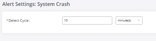
- Detect Cycle: The GXW450X will detect the event at each cycle based on the specified time. Users can enter the number and then select second(s)/minute(s)/hour(s)/day(s) to configure the cycle.
Click on the switch ![]()
![]() to turn on/off the alert and Email notification for the event. Users could also select the checkbox for each event and then click on buttons “Alert On”, “Alert Off”, “Email Notification On”, or “Email Notification Off” to control the alert and Email notification configuration.
to turn on/off the alert and Email notification for the event. Users could also select the checkbox for each event and then click on buttons “Alert On”, “Alert Off”, “Email Notification On”, or “Email Notification Off” to control the alert and Email notification configuration.
Alert Contact
Users could add the administrator’s Email address under Web GUI🡪Maintenance🡪System Events🡪Alert Contact to send the alert notification. Up to 10 Email addresses can be added.
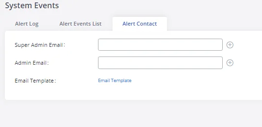
Upgrade
The GXW450X can be upgraded to a new firmware version remotely or locally. This section describes how to upgrade your GXW450X via network or local upload.
Upgrading via Network
The GXW450X can be upgraded via TFTP/HTTP/HTTPS by configuring the URL/IP Address for the TFTP/HTTP/HTTPS server and selecting a download method. Configure a valid URL for TFTP, HTTP, or HTTPS; the server name can be FQDN or IP address.
The upgrading configuration can be accessed via Web GUI🡪Maintenance🡪Upgrade.
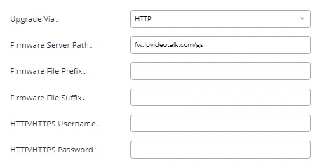
Upgrade Via | Allow users to choose the firmware upgrade method: TFTP, HTTP, or HTTPS. |
Firmware Server Path | Configures firmware server path. For example, firmware.grandstream.com |
Firmware File Prefix | If configured, only the firmware with the matching encrypted prefix will be downloaded. |
Firmware File Suffix | If configured, only the firmware with the matching encrypted postfix will be downloaded. |
HTTP/HTTPS User Name | The user name for the HTTP/HTTPS server. |
HTTP/HTTPS Password | The password for the HTTP/HTTPS server. |
Network Upgrade Configuration
Please follow the steps below to upgrade the firmware remotely.
- Enter the firmware server path under Web GUI🡪Maintenance🡪Upgrade.
- Click on “Save”. Then reboot the device to start the upgrading process.
- Please be patient during the upgrading process. Once done, a reboot message will be displayed in the LCD.
- Manually reboot the GXW450X when it’s appropriate to avoid immediate service interruption. After it boots up, log in to the Web GUI to check the firmware version.
Upgrading via Local Upload
If there is no HTTP/TFTP server, users could also upload the firmware to the GXW450X directly via Web GUI. Please follow the steps below to upload firmware locally.
- Download the latest GXW450X firmware file from the following link and save it on your PC: https://www.grandstream.com/support/firmware
- Log in to the Web GUI as an administrator on the PC.
- Go to Web GUI🡪Maintenance🡪Upgrade, upload the firmware file by clicking on
 and select the firmware file from your PC. The default firmware file name is gxw4500fw.bin
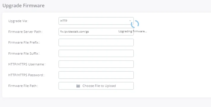
- Wait until the upgrading process is successful and a window will be popped up in the Web GUI requesting to confirm the reboot of the GXW450X for the changes to take effect.
- Click on “OK” to reboot the GXW450X and check the firmware version after it boots up.
Upgrading via a Local Server
Users can download a free TFTP, FTP, or HTTP server and conduct a local firmware upgrade. A free window version TFTP server is available for download from:
http://www.solarwinds.com/products/freetools/free_tftp_server.aspx
Please check our website at https://www.grandstream.com/support/firmware for the latest firmware.
Instructions for local firmware upgrade via TFTP:
- Unzip the firmware files and put all of them in the root directory of the TFTP server;
- Connect the PC running the TFTP server and the GXW450X to the same LAN segment;
- Launch the TFTP server and go to the File menu🡪Configure🡪Security to change the TFTP server’s default setting from “Receive Only” to “Transmit Only” for the firmware upgrade;
- Start the TFTP server and configure the TFTP server in the GXW450X web configuration interface;
- Configure the Firmware Server Path to the IP address of the PC;
- Update the changes and reboot the GXW450X.
End users can also choose to download a free HTTP server from http://httpd.apache.org/ or use
Microsoft IIS web server.
No Local Firmware Server
For users that would like to use remote upgrading without a local TFTP/FTP/HTTP server, Grandstream
offers a NAT-friendly HTTP server. This enables users to download the latest software upgrades for the
gateway via this server. Please refer to the following webpage for the firmware server path to use:
Backup
The GXW450X configuration can be backed up locally or via the network. The backup file will be used to restore the configuration on GXW450X when necessary.
Backup/Restore
Users could back up the GXW450X configurations for restore purposes under Web GUI🡪Maintenance🡪Backup🡪Backup/Restore. Click on ![]() to create a new backup. Then the following dialog will show:
to create a new backup. Then the following dialog will show:
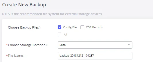
- Choose the files to be included in the backup.
- Choose where to store the backup file: USB Disk, SD Card, or Local.
- Name the backup file.
- Click on “Backup” to start the backup.
Once the backup is done, the list of the backups will be displayed with the date and time on the web page. Users can download ![]() , restore
, restore ![]() , or delete
, or delete ![]() it from the GXW450X internal storage or the external device.
it from the GXW450X internal storage or the external device.
Click on
![]() to upload backup file from the local device to GXW450X. The uploaded backup file will also be displayed in the web page and can be used to restore the GXW450X.
to upload backup file from the local device to GXW450X. The uploaded backup file will also be displayed in the web page and can be used to restore the GXW450X.

The ![]() option allows GXW450X to perform automatic backup at the user-specified time. Scheduled backup files can only be stored on a USB / SD card / SFTP server. Users can set backup time from 0-23 and how frequently the backup will be performed.
option allows GXW450X to perform automatic backup at the user-specified time. Scheduled backup files can only be stored on a USB / SD card / SFTP server. Users can set backup time from 0-23 and how frequently the backup will be performed.
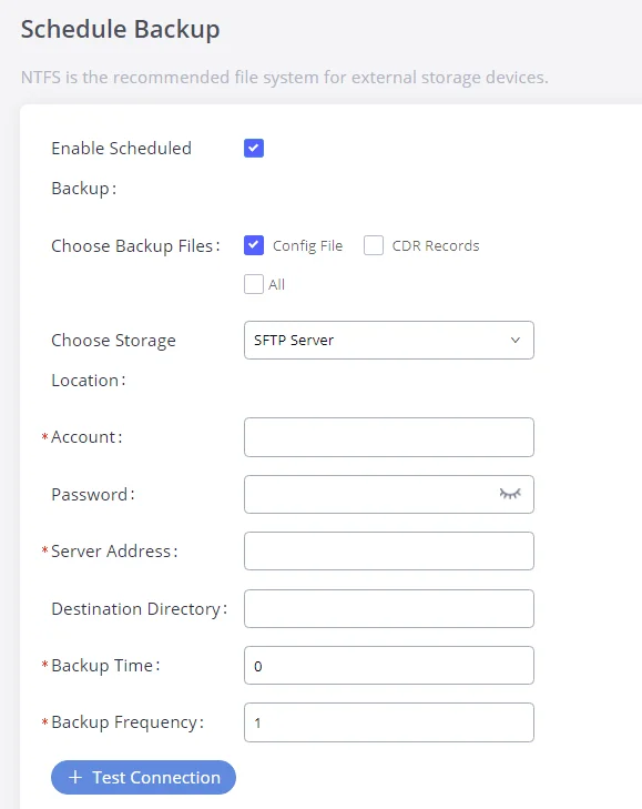
Data Sync
Besides local backup, users could backup the voice records and/or CDR on a daily basis to a remote server via SFTP protocol automatically under Web GUI🡪Maintenance🡪Backup🡪Data Sync.
The client account supports special characters such as @ or “.”. This change allows users to use an email address as SFTP accounts. It allows users as well to specify the destination directory on the SFTP server for the backup files. If the directory doesn’t exist on the destination, GXW450X will create the directory automatically.
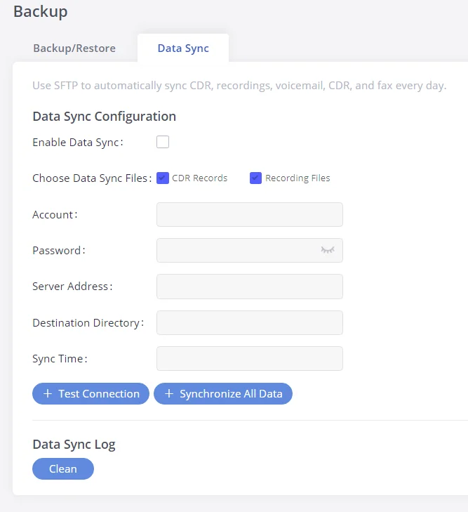
Enable Data Sync | Enable the auto backup function. This option is disabled by default |
Choose Data Sync Files | Choose the files to sync |
Account | Enter the Account name on the SFTP backup server. |
Password | Enter the Password associate with the Account on the SFTP backup server. |
Server Address | Enter the SFTP server address. |
Destination Directory | Specify the directory in the SFTP server to keep the backup file. Format: ‘xxx/xxx/xxx’, If this directory does not exist, GXW will create this directory automatically. |
Sync Time | Enter 0-23 to specify the backup hour of the day. |
Data Sync Configuration
Before saving the configuration, users could click on “Test Connection”. The GXW450X will then try connecting the server to make sure the server is up and accessible for the GXW450X.
Save the changes and all the backup logs will be listed on the web page.
Restore Configuration from Backup File
To restore the configuration on the GXW450X from a backup file, users could go to Web GUI🡪Maintenance🡪Backup🡪Backup/Restore.
- A list of previous configuration backups is displayed on the web page. Users could click on
 of the desired backup file and it will be restored to the GXW450X.
 - If users have other backup files on the PC to restore on the GXW450X, click on “Upload Backup File” first and select it from the local PC to upload on the GXW450X. Once the uploading is done, this backup file will be displayed in the list of previous configuration backups for restoring purposes. Click on to restore from the backup file.
- Users could also restore using the backup file saved on an SD card or USB device plugged into the GXW450X.
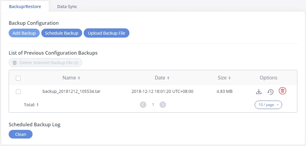
System Cleanup/Reset
Reset & Reboot
Users could perform reset and reboot under Web GUI🡪Maintenance🡪System Cleanup/Reset🡪Reset & Reboot. To factory reset the device, select the mode type first. There are two different types of reset.
- User Data: The data such as CDR Records Operation Logs Core file etc.
- All: Restore the device to factory default settings for both User Data and User Configuration.
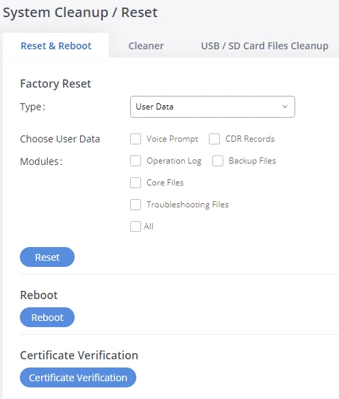
-
Press
 to factory reset the GXW450X.
-
Press
 to reboot the unit.
-
Press
 to validate certificate chain for the server’s certificate.
Cleaner
Users could configure to clean the Call Detail Report/Voice Records/Voice Mails/FAX automatically under Web GUI🡪 Maintenance🡪System Cleanup/Reset 🡪Cleaner.
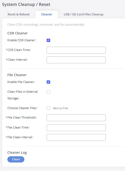
CDR Cleaner | |
Enable CDR Cleaner | Enable the CDR Cleaner function. |
CDR Clean Time | Enter 0-23 to specify the hour of the day to clean up CDR. |
Clean Interval | Enter 1-30 to specify the day of the month to clean up CDR. |
File Cleaner | |
Enable File Cleaner | Enter the Voice Records Cleaner function. |
Clean Files in External Device | If enabled the files in an external device (USB/SD card) will be atomically cleaned up as configured. |
Choose Cleaner File | Select the files for system automatic clean. |
File Clean Threshold | Specify the threshold of local storage usage from 0 to 99 (in percentage). |
File Clean Time | Enter 0-23 to specify the hour of the day to clean up the files. |
File Clean Interval | Enter 1-30 to specify the day of the month to clean up the files. |
Cleaner Log | Press the “Clean” button to clean the cleaner log. |
Cleaner Configuration
USB/SD Card Files Cleanup
Users could manage the content of the external drives, USB and /or SD card, manually from the Web GUI under Maintenance🡪System Cleanup/Reset 🡪USB / SD Card Files Cleanup.
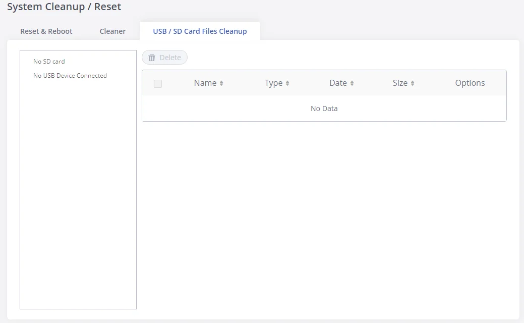
On this Web page, users could navigate through the paths and the directories of the USB and/or the SD card and select the files and folders to clean up.
Network Troubleshooting
On the GXW450X, users could capture traces, ping remote host and traceroute remote host for troubleshooting purposes under Web GUI🡪Maintenance🡪Network Troubleshooting.
Ethernet Capture
An ethernet trace can be captured for troubleshooting purposes related to network issues, the SIP flow, etc.
The captured trace can be downloaded for analysis. Instructions or results will be displayed in the Web GUI output result.
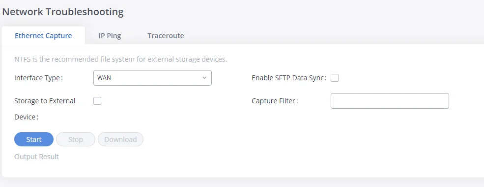
Interface Type | Select the network interface to monitor. 1. WAN 2. LAN 3. Both The default is “WAN”. |
Enable SFTP Data Sync | Check this box to save the capture files in the SFTP server. Please make sure the configuration of data synchronization works in advance. |
Storage to External Device | Check this box to activate storage of the capture either on the USB or SD Card. |
Capture Filter | Enter the filter to obtain the specific types of traffic, such as (host, src, dst, net, proto…). |
Start | Click to start the trace. |
Stop | Click to stop the trace. |
Download | Click to download the trace if the trace is stored locally. |
Ethernet Capture Parameters
The output result is in .pcap format. Therefore, users could specify the capture filter as used in the general network traffic capture tool (host, src, dst, net, protocol, port, port range) before starting to capture the trace.
IP Ping
Enter the Target Host using either a hostname or an IP address. Then press the “Start” button. The output result will dynamically be displayed in the window below.
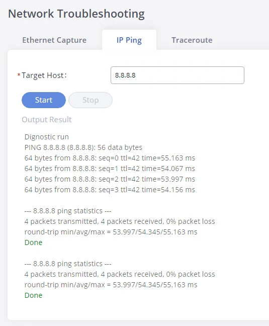
Traceroute
Enter the target host in hostname or IP address. Then press the “Start” button. The output result will dynamically be displayed in the window below.
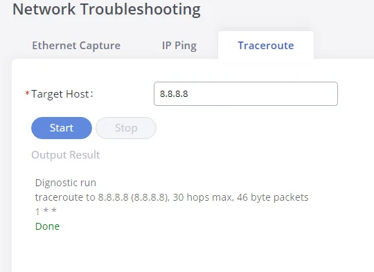
Signaling Troubleshooting
Please refer to the [Digital Trunk Troubleshooting] section.
Service Check
Enable Service Check to periodically check the GXW450X responsiveness. Check Cycle is configurable in seconds and the default setting is 60 sec. Check Times is the maximum number of failed checks before restarting the GXW450X. The default setting is 3. If there is no response from GXW450X after 3 attempts (default) to check, the current status will be stored and GXW450X will be restarted.
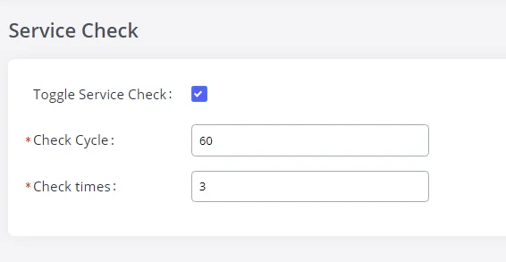
CDR (CALL DETAIL RECORD)
CDR (Call Detail Record) is a data record generated by the PBX that contains attributes specific to a single instance of a phone call handled by the PBX. It has several data fields to provide a detailed description of the call, such as the phone number of the calling party, phone number of the receiving party, start time, call duration, etc.
CDR Filter
On the GXW450X, the CDR can be accessed under Web GUI🡪CDR🡪CDR. Users could filter the call report by clicking on ![]() and specifying the date range and criteria, depending on how the users would like to include the logs in the report. Click on the “Search” button to display the generated report.
and specifying the date range and criteria, depending on how the users would like to include the logs in the report. Click on the “Search” button to display the generated report.
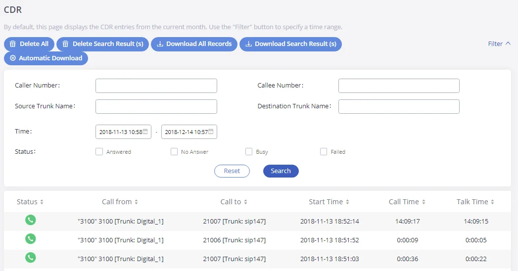
Caller Number | You can specify a caller number or set a caller number with a pattern (. match zero or more characters only appears in the end. X match any digit from 0-9, case-insensitive, repeatable, and only appears in the end. If the pattern string contains “.” in the end, “X” must appear before “.”.). For Example:
X: It will filter out CDR records where a caller number is of ranges from 0 to 9. XXXX: It will filter out CDR records where a caller number has 4 digits. 3XXX: It will filter out CDR records where a caller number has a leading digit of 3 and a length of 4 digits. 3.: It will filter out CDR records where a caller number has a leading digit 3.
|
Callee Number | Enter the caller name to filter the CDR report. CDR with the matching caller name will be filtered out. |
Source Trunk Name | Select source trunk(s) and the CDR of calls going through inbound trunk(s) will be filtered out. |
Destination Trunk Name | Select destination trunk(s) and the CDR of calls going outbound through the trunk(s) will be filtered out. |
Time | Specify the start time and the end time to filter the CDR report. Click on the calendar icon on the right and the calendar will show for users to select the exact date and time. |
Status | Filter with the call status, the available statuses are the following:
Answered No Answer Busy Failed
|
CDR Filter parameters
The call report will display as the following figure shows.
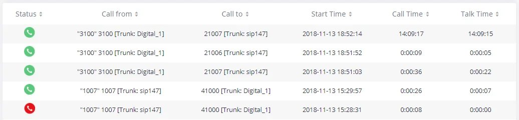
The CDR report has the following data fields:
- Status
Answered, Busy, No answer, or Failed.
- Call From
Example format: “3100” 3100 [Trunk: Digital_1]
- Call To
Example format: 21007 [Trunk: sip147]
- Start Time
Example Format: 2018-11-13 18:52:14
- Call Time
Example Format: 0:00:08
- Talk Time
Example Format: 0:00:07
After applying the filter, Users could perform the following operations on the CDR report:
- Sort by data field
Click on the header of the data field column to sort the report according to an ascending or descending order. Clicking on the same header again to reverse the order.
- Download the search result
Click on
![]() to export the records filtered out to a .csv file.
to export the records filtered out to a .csv file.
- Delete search result
On the bottom of the page, click on
![]() button to remove CDR records that appear on search results.
button to remove CDR records that appear on search results.
- Delete all records
Click on
![]() button to remove all the call report information.
button to remove all the call report information.
- Download all records.
Click on
![]() to export all the records to a .csv file.
to export all the records to a .csv file.
Automatic Download
Users could configure the GXW450X to automatically download the CDR records and send the records to an Email address. Click on “Automatic Download Settings” and configure the parameters in the dialog below.
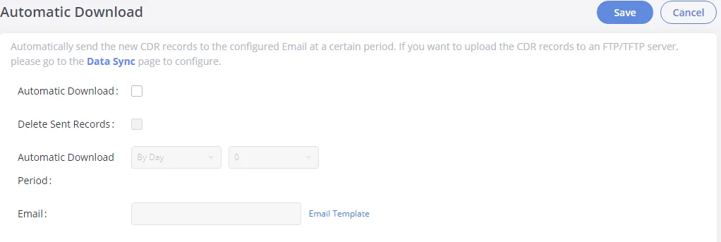
To receive CDR records automatically from Email, check “Enable” and select a time period “By Day” “By Week” or “By Month”, and select Hour of the day as well for the automatic download period. Make sure you have entered an Email or multiple email addresses where to receive the CDR records.
CDR Report Data Fields
The CSV CDR report file downloaded will have the following data fields.
Field | Type | Description | Access |
Account Code | String | An account code associated with the Party A channel. | r/w |
Caller Number | String | The Caller ID number. | r |
Callee Number | String | The destination number. | r |
Context | String | The context of the call. | r |
CallerID | String | The caller ID. | r |
Source Channel | String | The name of the source channel. | r |
Dest Channel | String | The name of the destination channel. | r |
Lastapp | String | The last application the Party A channel executed. | r |
Lastdata | String | The application data for the last application the Party A channel executed. | r |
Start time | Date/time | The time the CDR was created. | r |
Answer Time | Date/time | The time when Party A was answered, or when the bridge between Party A and Party B was created. | r
|
End time | Date/time | The time when the CDR was finished. This occurs when either party hangs up, or when the bridge between the parties is broken. | r |
Call time | Integer | The time in seconds from start time until the end time. | r |
Talk time | Integer | The time in seconds from answer time until the end time. | r |
Disposition | Enum | The final known disposition of the CDR record. The possible values are: “ANSWERED”, “NO ANSWER, CONGESTION, FAILED, and BUSY. | r
|
Amaflags | Enum | A flag is specified on the Party A channel. The possible values are: “OMIT, BILLING, and DOCUMENTATION. | r/w |
Uniqueid | String | A unique identifier for the Party A channel | r |
Userfield | String | A user-defined field set on the channels. If set on both the Party A and Party B channels, the user fields of both are concatenated and separated by a comma. | r/w
|
Dest Channel Extension | String | The destination extension of the call | r |
Caller Name | String | The name of the caller | r |
Answer by | String | The extension to be called | r |
Session | String | A numeric value that, combined with uniqueid and linkedid, can be used to uniquely identify a single CDR record | r |
Action Owner | String | The party that made the call | r |
Action Type | String | The action type of the call | r |
Source Trunk Name | Sting | The inbound route trunk name | r |
Dest Trunk Name | String | The outbound route trunk name | r |
CDR Report Data Fields
Example of a CDR report Data fields:
- Account code: —
- Caller Number: 1008
- Callee number: 1006
- Context: did-out
- Caller ID: “” <1008>
- Source Channel: DAHDI/i1-1-1
- Dest Channel: PJSIP/trunk_5-00000000
- Lastapp: Dial
- Lastdata: PJSIP/1006@trunk_5,,b(callee-handler^s^1)
- Start time: 11/13/2018 3:01:28 PM
- Answer time: 11/13/2018 3:01:31 PM
- End time: 11/13/2018 3:01:50 PM
- Call time: 22 (in seconds)
- Talk Time: 18
- Disposition: ANSWERED
- Amaflags: DOCUMENTATION
- UniqueID: 1542092488
- Userfield: External
- Dest channel extension: trunk_5
- Caller name: –
- Answer by: trunk_5
- Session: 1542092488529109-1008
- Action owner: 1008
- Action type: DIAL.
- Source Trunk name: Digital_1
- Dest Trunk name: sip147
CHANGE LOG
This section documents significant changes from previous versions of GXW450X user manuals. Only major new features or major document updates are listed here. Minor updates for corrections or editing are not documented here.
Firmware version 1.0.1.13
- Added new option Anonymous call IE. [Anonymous call IE]
- Added new option Screening indicator when using SS7 signaling. [Screening indicator]
- Added new option to Enable Diversion Header. [Enable Diversion Header]
- Added ability to import and export DODs. [Exporting DODs] [Importing DODs]
- Added ability to set 1-digit DODs. [Direct Outward Dialing]
Firmware version 1.0.1.11
- Added new option “Original Called” when using SS7 signaling type. [Original Called]
- Added support for “early ACM” in SS7 interface settings. [Early ACM]
- Added new option PROGRESS to the Edit Digital Port. [PROGRESS]
- Added auth-user and auth-pass parameter support in OpenVPN. [User authentification]
- Added ability to provision TR-069 settings. [TR-069]
- Firewall rules will now apply to traffic between LAN and WAN interfaces. [Static Defense]
- Added E1/T1/J1 Error Code option to allow users to send either 480 or 503 response to the VoIP trunk when the E1/T1/J1 interface is down or unavailable. [E1/T1/J1 Error Code]
Firmware version 1.0.1.9
Firmware version 1.0.1.7
- Added the ability to customize call failure tone settings. [Call Failure Tone Settings]
- Added ability to group E1 lines with a single DATA channel. [Data channel]
- Added the ability to assign channel groups. [Digital Hardware Configuration]
- Added T1 E&M signaling support. [Table 30: Digital Hardware Configuration Parameters: T1 – E&M Immediate]
- Added Secondary SIP Server option to Register SIP Trunks. [Secondary SIP Server]
- Added Secondary Outbound Proxy option. [Backup Outbound Proxy]
- The administrator-level users can now view the SNMP page. [SNMP]
- Added GDMS support.
- Added ability to select a different E1/T1 port to use for the line’s data channel when SS7 is selected as the signaling type. [Data channel]
- Added ability to select the minimum and maximum TLS versions to support. [TLS Security]
- Added SNMP support. [SNMP]
- Added options From User, Send PPI Header, PPI Mode, and DOD as From Name. [Table 33: VoIP Trunk Configuration Parameters – Register SIP Trunk][Table 34: VoIP Trunk Configuration Parameters – Peer SIP Trunk]
- Added the ability to configure tone region. [Tone Region]
- Added the ability to configure DODs for VoIP trunks. [Direct Outward Dialing (DOD)]
- Added GAPS provisioning support.
- Added the Set Caller ID option to the Edit Inbound Rule page. [Set Caller ID Info]
- Added the Enable Filter on Source Caller ID option to the Edit Outbound Rule page. This option will allow only callers with the specified CID pattern to use the outbound route. [Enable Filter on Source Caller ID]
- No major changes.
- No major changes.
- No major changes.
- This is the initial version.