
WELCOME
Thank you for purchasing Grandstream DP752 DECT Cordless VoIP Base Station and DP730/DP722 DECT Cordless HD Handsets.
The DP752 is a powerful DECT VoIP base station that pairs with up to 5 of Grandstream’s DP series DECT handsets to offer mobility to business and residential users. It supports a range of up to 400 meters with DP730 and up to 350 meters with DP722/DP720 outdoors and 50 meters indoors to give users the freedom to move around their work or home space, delivering efficient flexibility. This DECT VoIP base station supports up to 10 SIP accounts and 5 concurrent calls while also offering 3-way voice conferencing, full HD audio and integrated PoE. A shared SIP account on all handsets will add seamless unified features that give users the ability to answer all calls regardless of location in real-time. The DP752 supports a variety of auto-provisioning methods and TLS/SRTP/HTTPS encryption security. When paired with Grandstream’s DP720, DP722 or DP730 handsets, the DP752 offers a powerful cordless DECT solution for any business or residential user.
The DP730 is a DECT cordless IP phone that allows users to mobilize their VoIP network throughout any business, warehouse, retail store and residential environment. It is supported by Grandstream’s DP750 and DP752 DECT VoIP base stations and delivers a combination of mobility and top-notch telephony performance. Up to five DP730 handsets are supported on each base station while each DP730 supports a range of up to 400 meters outdoors and 50 meters indoors from the base station. It touts a suite of robust telephony features including support for up to 10 SIP accounts and 2 concurrent calls per handset, full HD audio, a 3.5mm headset jack, push-to-talk, a speakerphone and more. When paired with Grandstream’s DECT Base Stations, the DP730 offers a powerful cordless DECT solution for any business or residential user.
The DP722 is a DECT cordless IP phone that allows users to mobilize their VoIP network throughout any business, warehouse, retail store and residential environment. It is supported by Grandstream’s DP750 and DP752 DECT VoIP base stations and delivers a combination of mobility and top-notch telephony performance. Up to five DP722 handsets are supported on each base station while each DP722 supports a range of up to 350 meters outdoors and 50 meters indoors from the base station. It touts a suite of robust telephony features including support for up to 10 SIP accounts and 2 concurrent calls per handset, full HD audio, a 3.5mm headset jack, push-to-talk, a speakerphone and more. When paired with Grandstream’s DECT Base Stations, the
DP722 offers a powerful cordless DECT solution for any business or residential user.
PRODUCT OVERVIEW
Feature Highlights
The following tables contain the major features of the DP752 / DP730/DP722:
 DP752 |
|
P752 Features at a Glance
 DP722 |
|
DP722 Features at a Glance
 DP730 |
|
DP730 Features at a Glance
DP752 Technical Specifications
The following table resumes all the technical specifications including the protocols / standards supported, voice codecs, telephony features, languages, and upgrade/provisioning settings for the Base station DP752.
Air Interface | Telephony standards: DECT Frequency bands:
Number of channels: 10 (Europe), 5 (US, Brazil or Japan), 3 (Korea), 8 (Taiwan) Range: Up to 400 meters with DP730 and up to 350 meters with DP722/DP720 outdoor / 50m range indoor. |
Peripherals | 3 LED indicators: Power, Network, DECT. Pairing/Paging button. One 10/100 Mbps auto-sensing Ethernet port with integrated PoE |
Protocols/Standards | SIP RFC3261, TCP/IP/UDP, RTP/RTCP, HTTP/HTTPS, ARP/RARP, ICMP, DNS (A record, SRV, NAPTR), DHCP, PPPoE, SSH, TFTP, NTP, STUN, SIMPLE, LLDP-MED, LDAP, TR-069, 802.1x, TLS, SRTP |
Voice Codecs | G.711μ/a-law, G.723.1, G.729A/B, G.726-32, iLBC, G.722, OPUS, G.722.2/AMR-WB (special order), in-band and out-of-band DTMF (in audio, RFC2833, SIP INFO), VAD, CNG, PLC, AJB |
Telephony Features | Hold, transfer, forward, 3-way conference, push to talk, intercom, downloadable phonebook (XML, LDAP, up to 3000 entries), call waiting, call log (up to 300 records), auto answer, flexible dial plan, server redundancy and fail-over |
QoS | Layer 2 QoS (802.1Q, 802.1p) and Layer 3 QoS (ToS, DiffServ, MPLS) |
Security | User and administrator level access control, MD5 and MD5-sess based authentication, 256-bit AES encrypted configuration file, TLS, SRTP, HTTPS, 802.1x media access control, DECT authentication & encryption |
Multi-language | Chinese Simple, Chinese Tradition, Czech, Danish, Dutch, English, Estonian, Finnish, French, German, Hebrew, Hungarian, Japanese, Korean, Norwegian, Portuguese, Romanian, Spanish, Swedish, Turkish. |
Upgrade/ Provisioning | Firmware upgrade via FTP/FTPS or /HTTP/HTTPS, mass provisioning using TR-069 or AES encrypted XML configuration file |
Multiple SIP Accounts | Up to ten (10) distinct SIP accounts per system Each handset may map to any SIP account(s) Each SIP account may map to any handsets(s) |
Ring Group | Flexible options when multiple handsets share the same SIP account
All phones ring sequentially, starting with the phone after the one which rang last.
All phones ring sequentially in the predetermined order, starting with the first phone each time.
All phones ring concurrently; after one phone answers, the remaining available phones can make new calls |
Power & Green Energy Efficiency | Universal Power Supply Input AC 100-240V 50/60Hz; Output 5VDC, 1A; Micro-USB connection; PoE: IEEE802.3af Class 1, 0.44W–3.84W |
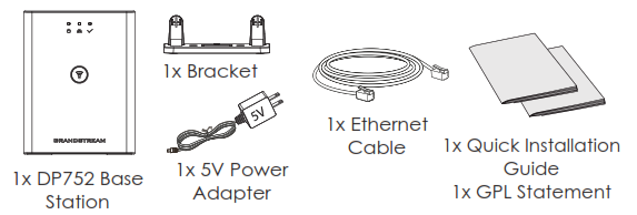
Package Content | Base unit, Universal Power Supply, Ethernet cable, Quick Installation Guide, GPL Statement |
Dimensions (H x W x D) | 140.31 x 64.98 x 105 mm |
Weight | Base unit: 140g; Universal power supply: 50g; Package: 370g |
Temperature and Humidity | Operation: -10º to 50ºC (14 to 122ºF); Storage: -20º to 60ºC (-4 to 140ºF); Humidity: 10% to 90% non-condensing |
Compliance | FCC: FCC Part 15B; FCC Part 15D;MPE; FCC ID CE:EN 55032; EN 55035; EN 61000-3-2; EN 61000-3-3; EN 60950-1; EN 301 489-1/-6; EN 301 406; EN 50385; RED NB Cert RCM:AS/NZS 32; AS/NZS 60950.1. ANATEL, EAC, UL(adapter). |
DP730 Technical Specifications
The following table resumes all the technical specifications including the protocols / standards supported, voice codecs, telephony features, languages and upgrade/provisioning settings for the DP730 handsets.
Air Interface | Telephony standards: DECT Frequency bands:
Number of channels: 10 (Europe), 5 (US, Brazil or Japan), 3 (Korea), 8 (Taiwan) Range: up to 400 meters outdoor and 50 meters indoor |
Peripherals | 2.4 inch (240×320) color TFT LCD 27 keys including 3 soft keys, 5 navigation/ menu keys, 4 dedicated function keys for SEND, POWER/END, SPEAKERPHONE, MUTE, 3 side keys including 2 volume (up and down) and 1 Push-to-Talk key 3-color MWI LED 3.5mm headset jack Proximity and accelerometer sensors Backlit keypad Removable belt clip Micro-USB port for alternative charging and non-battery operation |
Protocols/Standards | Hearing Aid Compatibility (HAC) compliant |
Voice Codecs | G.722 codec for HD audio and G.726 codec for narrow band audio (G.711μ/a-law, G.723.1, G.729A/B, iLBC and OPUS are supported via companion DECT base station), AEC, AGC, Ambient noise reduction on handset mic, advanced noise suppression for incoming audio |
Telephony Features | Hold, transfer, forward, 3-way conference, push-to-talk, intercom, downloadable phonebook, call waiting, call log, auto answer, click-to-dial, flexible dial plan |
HD Audio | Yes, in both Handsets and Speakerphone modes |
Security | DECT authentication & encryption |
Multi-language | English, Czech, German, Spanish, French, Hebrew, Italian, Dutch, Polish, Portuguese, Russian, Turkish, Arabic, Chinese Simple, Chinese Tradition, Japanese, Korean, Slovakian, Serbian, Greek, Swedish. |
Upgrade/ Provisioning | Software Upgrade Over-The-Air (SUOTA), handsets provisioning Over-The-Air |
Multiple Line Access | Each handset may access up to twenty (20) lines |
Power & Green Energy Efficiency | Universal Power Supply Input AC 100-240V 50/60Hz; Output 5VDC 1A; Micro-USB connection; Rechargeable Li-ion battery (500 hours of standby time and 40 hours of talk time) |
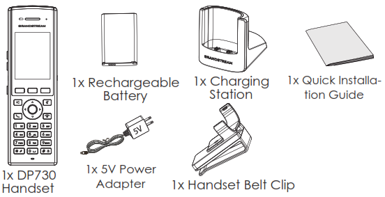
Package Content | Handset unit, universal power supply, charger cradle, belt clip, 1 battery, Quick Installation Guide |
Dimensions (H x W x D) | Handset: 168.5 x 52.5 x 21.8mm; Charger cradle: 76 x 73 x 81mm |
Weight | Handset: 180g; Charger cradle: 78g; Universal power supply: 50g; Package: 465g |
Temperature and Humidity | Operation: -10º to 50ºC (14 to 122ºF); Charging: 0 to 45ºC (32 to 113ºF); Storage: -20º to 60ºC (-4 to 140ºF); Humidity: 10% to 90% non-condensing |
Compliance | FCC, CE, RCM, IC |
Table 5: DP730 Technical Specifications
DP722 Technical Specifications
The following table resumes all the technical specifications including the protocols / standards supported, voice codecs, telephony features, languages and upgrade/provisioning settings for the DP722 handsets.
Air Interface | Telephony standards: DECT Frequency bands:
Number of channels: 10 (Europe), 5 (US, Brazil or Japan), 3 (Korea), 8 (Taiwan) Range: up to 350 meters outdoor and 50 meters indoor |
Peripherals | 1.8 inch (128×160) color TFT LCD 23 keys including 2 softkeys, 5 navigation / menu keys, 4 dedicated function keys for SEND, POWER/END, SPEAKERPHONE, MUTE 3-color MWI LED 3.5mm headset jack Removable belt clip Micro-USB port for alternative charging and non-battery operation |
Protocols/Standards | Hearing Aid Compatibility (HAC) compliant |
Voice Codecs | G.722 codec for HD audio and G.726 codec for narrow band audio (G.711μ/a-law, G.723.1, G.729A/B, iLBC and OPUS are supported via companion DECT base station), AEC, AGC, Ambient noise reduction on handset mic, advanced noise suppression for incoming audio |
Telephony Features | Hold, transfer, forward, 3-way conference, push-to-talk, intercom, downloadable phonebook, call waiting, call log, auto answer, click-to-dial, flexible dial plan |
HD Audio | Yes, in both Handsets and Speakerphone modes |
Security | DECT authentication & encryption |
Multi-language | English, Czech, German, Spanish, French, Hebrew, Italian, Dutch, Polish, Portuguese, Russian, Turkish, Arabic, Chinese Simple, Chinese Tradition, Japanese, Korean, Slovakian, Serbian, Greek, Swedish. |
Upgrade/ Provisioning | Software Upgrade Over-The-Air (SUOTA), handsets provisioning Over-The-Air |
Multiple Line Access | Each handset may access up to twenty (20) lines |
Power & Green Energy Efficiency | Universal Power Supply Input AC 100-240V 50/60Hz; Output 5VDC 1A; Micro-USB connection; Rechargeable 800mAh Ni-MH Low Self-Discharge (LSD) AAA batteries (250 hours of standby time and 20 hours of talk time) |
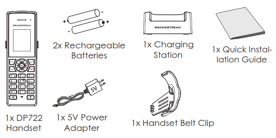
Package Content | Handset unit, universal power supply, charger cradle, belt clip, 2 batteries, Quick Start Guide |
Dimensions (H x W x D) | Handset: 158 x 50 x 28.1mm; Charger cradle: 81.15 x 75.89 x 36.36mm |
Weight | Handset: 110g; Charger cradle: 44g; Universal power supply: 50g; Package: 328g |
Temperature and Humidity | Operation: -10º to 50ºC (14 to 122ºF); Charging: 0 to 45ºC (32 to 113ºF); Storage: -20º to 60ºC (-4 to 140ºF); Humidity: 10% to 90% non-condensing |
Compliance | FCC, CE, RCM, IC |
Table 6: DP722 Technical Specifications
GETTING STARTED
This chapter provides basic installation instructions including the list of the packaging contents and also information for obtaining best performance with the DP730/DP722 DECT Cordless HD Handsets and the DP752 DECT Cordless VoIP Base Station.
Equipment Packaging
DP752 |
|
DP730 |
|
|
Connecting DP752
To setup the DP752 Cordless VoIP Base Station, please follow the steps below:
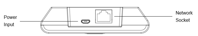
You have two options for power and network connection of the base station: AC power or Power over Ethernet (PoE).
Connecting via AC power
- Connect the micro-USB connector into the related port on the base station and connect the other end of the power adapter into an electrical power outlet.
- Connect the supplied Ethernet cable between the Internet port on the base station and the Internet port in your network or the switch/hub device port.
Connecting via PoE
To connect the base station using PoE, you need to connect the Ethernet cable provided (or 3rd party network cable) between the Network Socket on the base station to Ethernet port of your PoE switch/hub.
Setting up DP730/DP722 Handsets
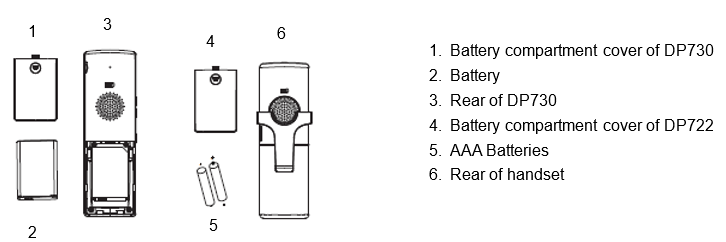
Please follow below steps to insert batteries into the Handsets:
- Open the battery compartment cover.
- For DP730: Inset Li-ion battery with the electrodes in the bottom left corner.
- For DP722: Insert AAA batteries with correct polarity (+ / -).
- Close the battery compartment cover.
Battery Information
DP722 Batteries Specifications | DP730 battery specifications |
|
In order to get the best performance of your DP730/DP722 Handsets, we recommend using original batteries provided in the package or batteries compliant with above specifications.
The specifications may differ depending on the age and capacity of the batteries used.
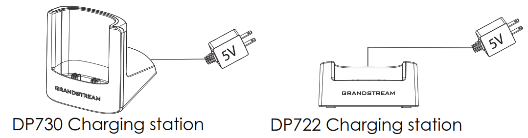
Setting up the Charge Station
Please refer to the following steps for setting up the charge station and charging the Handsets:
- Connect the DC plug on the power adapter to the micro-USB connector on the charge station.
- Connect the other end of the power adapter into an electrical power outlet.
- After setting up the Handsets and the charge station, place the Handsets in the charge station.
DP752 LED Patterns
The DP752 has 5 LED lights on it. Please refer to the following table for the meaning of each light.

| LED Light | Status |
|---|---|
LED Light | Status |

| Indicates Power ON/OFF. |

| Indicates status of SIP account registration and network
|

| Indicates status of the DECT handset registration:
|
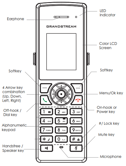
DP730/DP722 Handsets Description
The LCD screen and the Keypad are the main hardware components of the DP730/DP722.
| Key | Description | |
|---|---|---|
1. | Earphone | Delivers audio output. |
2. | LED Indication | Red: Charging. Green: Charge completed. Blinking: Missed call(s) or Voice Mail received. |
3,5 | Left and right softkeys | Correspond to functions displayed on the LCD. These functions change depending on the current context. |
4. | LCD display | Shows call information, handset status icons, prompt messages, etc. |
6. | 4 Arrow key combination | Permits navigation of the cursor through the displayed menu options. |
7. | Men/Ok key | Selects the option chosen by the cursor. (Enters the main menu from the home screen.) |
8. | Off-hook / Dial key | Enters dialing mode, or dials number entered. |
9. | On-hook / Power key | Terminates calls or turns the handset on / off. |
10. | Alphanumeric Keypad | Provides the digits, letters, and special characters in context-sensitive applications. For + sign, press and hold key 0. |
11. | # / Lock key | Locks keypad against unintentional entries when keep pressing #.
Press Unlock softkey and then # to unlock the keys. |
12. | Mute key | Activates or deactivates the mute feature. |
13. | Hands-free / Speaker key | Switches between handset and hands-free / speaker modes. |
14. | Microphone | Picks up audio earpiece and hands-free calls. |
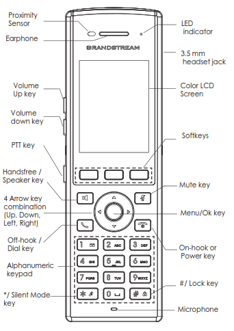
| Key | Description | |
|---|---|---|
1. | Proximity sensor | The proximity senor can detect and measure gravitational acceleration, tilt, vibration, altitude changes, and static position. |
2. | Earphone | Delivers audio output. |
3,4 | Volume up / Down Keys | Configure the handset and ringtone volume. |
5. | PTT Key | PTT (Push-to-Talk) button, to initiate PTT call. |
6. | Hands-free / Speaker key | Switches between Handset and Hands-free / Speaker modes. |
7. | Arrow key combination (Up, Down, Left, Right) | Allows navigation of the cursor through the displayed menu options. |
8. | Off-hook / Dial key | Enters dialing mode, or dials number entered. |
9. | Alphanumeric Keypad | Provides the digits, letters, and special characters in context-sensitive applications. For + sign, press and hold key 0. |
10. | * / Silent Mode key | Activates or deactivates the silent mode (no ringtone heard during incoming call) when keep pressing on * in idle screen. |
11. | LED indicator | 1dual-color LED indicator indicating: power, call, battery, message waiting… |
12. | 3.5 mm headset jack | Phone connector for the headphones/headsets. |
13. | Color LCD Screen | 2.4-inch (240×320) TFT color LCD |
14. | Softkeys | Correspond to functions displayed on the LCD. These functions change depending on the current context. |
15. | Mute | Mute microphone during conversation. |
16. | Menu/OK key | Selects the option chosen by the cursor or enters the main menu from the home screen. |
17. | On-hook or Power key | Terminates calls or turns the handset on / off. |
18. | # / Lock key | Locks keypad against unintentional entries when keep pressing #.
|
19. | Microphone | Picks up audio earpiece and hands-free calls. |
DP730/DP722 Icons Description
The following table contains description of each icon that might be displayed on the LCD screen of the DP730/DP722 Handsets.
Battery status Not equipped with a battery | |
Battery status Battery empty | |
Battery status Battery low | |
Battery status Battery normal | |
Battery status Battery full | |
Battery status Charging | |
Signal status Not subscribed | |
Signal status Not in range | |
Signal status Signal very low | |
Signal status Signal low | |
Signal status Signal normal | |
Signal status Signal good | |
Signal status Signal very good | |
Microphone MUTE Status OFF – Not muted ON – Muted | |
Speaker status OFF – The speaker is inactivated ON – The speaker is activated | |
 | Headset icon |
 | Missed Call icon |
 | Voicemail icon |
Ringtone status OFF – Ringtone off (Silent mode) ON – Ringtone on | |
Keypad Lock status OFF – Keypad unlock ON – Keypad locked | |
DND Status. OFF – Do Not Disturb disabled ON – Do Not Disturb enabled | |
 | Call waiting |
Information | |
Account not registered | |
Account Registered | |
Error message | |
Handset number | |
 | Incoming Call notification |
 | Outgoing Call notification |
Missed Call notification | |
 | Voicemail notification |
 | Contacts |
 | Call History |
 | Registration |
 | Voice Mail |
 | Preferences |
 | Shortcut |
 | Call Features |
 | Status |
 | Settings |
DP730/DP722 Icons Description
DP730/DP722 Handsets Menu
The Handsets has an easy-to-use menu structure. Every menu opens a list of options. To open the main menu, press “Menu” (left softkey) when the Handsets is on and in standby mode. Press Arrow keys to navigate to the menu option you require. Then press “Select” (left softkey) or OK/Selection key to access further options or confirm the setting displayed. To go to the previous menu item, press “Back” (right softkey). You can press Power key at any time to cancel and return to standby mode. If you do not press any key, the Handsets automatically reverts to standby mode after 20 seconds.
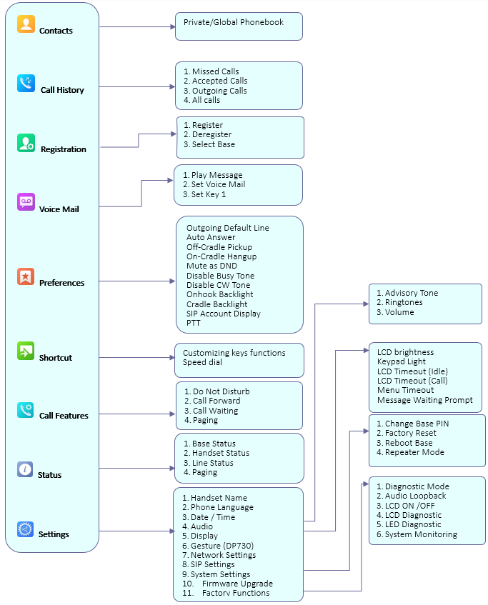
Contacts |
Note: Private/Global Phonebooks will be merged on the handset. |
Call History | Display the call history:
Note: You can add contacts to Shared Contacts directly from call logs. |
Registration |
|
Voice Mail |
|
Preferences |
|
Customizing keys functions | Customizing keys functions:
Select key and press OK button to configure function. Following functions are available for arrow keys: 1. Disabled, 2. Missed Calls, 3: Accepted Calls, 4: Outgoing Calls, 5: History, 6: Contacts, 7: Status, 8: Line, 9: Voice Mail, 10: Ringer Volume Up, 11: Ringer Volume Down, 12: Audio Volume Up, 13: Audio Volume Down, 14: Intercom.
Select a key [2], [3], [4], [5], [6], [7], [8] or [9] and press OK button. Select “Edit” to manually specify the destination number or select “From Contacts” to select a contact as speed dial destination. |
Call Features |
|
Status |
|
Settings |
All LEDs will light up, and the LCD will display a table listing the names of all keys in red. Press any key to diagnose; the key’s name will display in blue. After all keys are diagnosed, a prompt message (“PASS”) will display; press “Back” (right softkey) to exit. Note: User can long press arrow UP key to exit at any time.
|
CONFIGURATION GUIDE
The DP752 can be configured using:
- Web GUI embedded on the DP752 using PC’s web browser.
- LCD Configuration Menu using the paired DP730/DP722 keypad.
Via Web GUI you can configure all the functions supported by the DP752; while via paired DP730/DP722, you can access limited configuration and need the base station PIN code for some options.
Obtain DP752 Base Station IP Address via Paired DP730/DP722
DP752 is by default configured to obtain IP address from DHCP server where the unit is located. In order to know which IP address is assigned to your DP752, please follow below steps using a paired DP730/DP722 Handsets with your DP752 base station. Please see Register DP730/DP722 Handsets to DP752 Base Station .
- Press “Menu” (left softkey) or OK button on DP730/DP722 to view operation menu.
- Press Arrow (Up, Down, Left, Right) keys to move the cursor to Status icon
 , then press
“Select” (left softkey) or OK button, then select Base Status. - Using Arrow keys, navigate down to view the IP address of the DP752.
 , then press
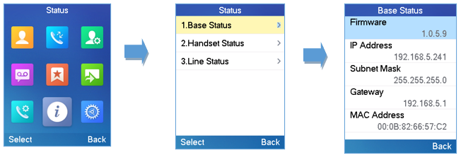
Configuration via Web Browser
The DP752 embedded Web server responds to HTTP/HTTPS GET/POST requests. Embedded HTML pages allow a user to configure the DP752 through a Web browser such as Google Chrome, Mozilla Firefox and Microsoft’s IE.
Accessing the Web UI
- Connect the computer to the same network as DP752.
- Make sure the DP752 is booted up.
- You may check DP752 IP address via a subscribed DP730/DP722 on its LCD menu at Status 🡪 Base Status 🡪 IP Address. Please see Obtain DP752 Base station IP Address via paired DP730/DP722
- Open Web browser on your computer.
- Enter the DP752’s IP address in the address bar of the browser.
- Enter the administrator’s username and password to access the Web Configuration Menu.
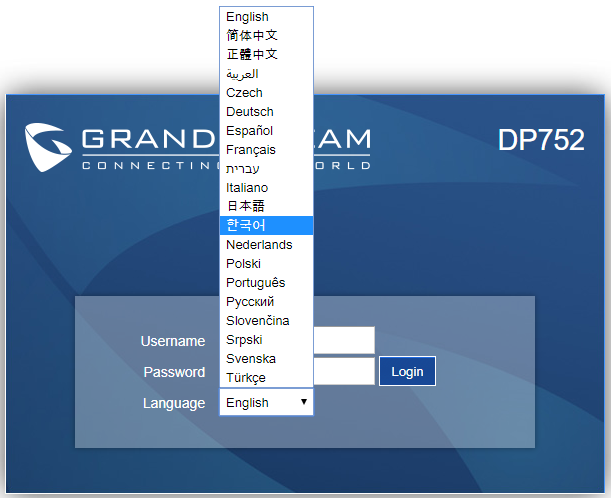
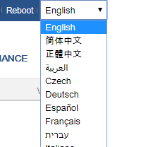
Web GUI Languages
Currently the DP752 series web GUI supports English, Czech, German, Spanish, French, Arabic, Hebrew, Italian, Russian, Netherlands, Japanese, Polish, Chinese Simple, Chinese Tradition, Korean, Portuguese, Slovakian, Serbian, Swedish and Turkish.
Users can select the displayed language in web GUI login page, or at the upper right of the web GUI after logging in
Icons Bar Shortcut
Users can find the icon bar right below the main menu of every page as displayed on following screenshot:
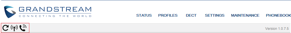
Please refer to following table describing the use of each icon:
| Icon | Description |
|---|---|

| Refresh Button: Allows users to refresh the current page. |

| Subscribe Button: Allows users to open the subscription. |

| Paging Button: Allows users to page all the registered DP730/DP722 Handsets. |
Saving the Configuration Changes
After users makes changes to the configuration, pressing the Save button will save but not apply the changes until the Apply button on the top of web GUI page is pressed. Users can instead directly press the Save and Apply button. We recommend rebooting or powering cycle the phone after applying all the changes.
Web UI Access Level Management
There are two default passwords for the login page:
User Level | Username | Password | Web Pages Allowed |
End User Level | user | Password defined by the administrator | Only Status, Settings and Maintenance |
Administrator Level | admin | Random password available on the sticker at the back of the unit. | All pages |
Changing User Level Password
- Access the Web GUI of your DP752 using the admin’s username and password.
- Press Login to access your settings.
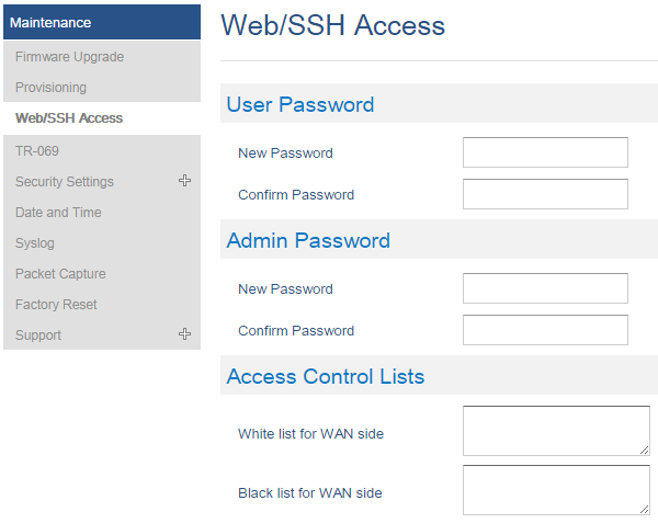
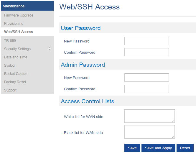
- Go to Maintenance 🡪 Web/SSH Access.
- In Web/SSH Access page, locate User Password section:
- Type in your new user password in New Password field.
- Type in again same entered password in Confirm Password field.
- Press Save and Apply to save your new setting.
Changing Admin Level Password
- Access the Web GUI of your DP752 using the admin’s username and password.
- Press Login to access your settings.
- Go to Maintenance 🡪 Web/SSH Access.
- In Web/SSH Access page, locate Admin Password section:
- Type in your new Admin Password in New Password field.
- Type in again same entered password in Confirm Password field.
- Press Save and Apply to save your new setting.
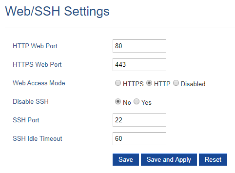
Changing HTTP / HTTPS Web Access Port
- Access the Web GUI of your DP752 using the admin’s username and password.
- Press Login to access your settings.
- Go to Maintenance 🡪 Security Settings 🡪 Web/SSH.
- In Web/SSH Settings page, locate HTTP / HTTPS Web Port field and change it to your desired/new HTTP / HTTPS port.
Note: By default, the HTTP port is 80 and HTTPS is 443. - Select the Web Access Mode depending on desired protocol (HTTP or HTTPS).
- Press Save and Apply to save your new setting.
Web Configuration Definitions
This section describes the options in the DP752 Web UI. As mentioned, you can log in as an administrator or an end user.
- Status: Display system info, network status, base and repeater status, account status, and line options.
- Profiles: Configure the profiles with general settings, network settings, SIP settings, audio settings, call settings and ring tones.
- DECT: Configure DECT general settings, account settings and Handsets line settings.
- Settings: Configure ring tones and system features.
- Maintenance: Configure networks, upgrading and provisioning, web/SSH access, TR-069, security settings, date and time, and syslog.
- Phonebook: Manage phonebooks: global (XML or LDAP) and private (XML).
Status Page Definitions
Account | Displays list of configured accounts’ names, from Account 1 to Account 10. |
SIP User ID | Displays list of SIP user id registered. |
SIP Server | Displays list of SIP Server. |
SIP Registration | Shows the status of SIP registration. If the SIP account is successfully registered, it will display “YES” with green background. If the SIP account is not registered, it will display “NO” with red background. |
HS Mode | Displays the HS mode configured for each account. |
HS status table |
Red: HS is not available.
For example, if accounts 1, 3 and 4 are assigned to HS3 with account 3 in use, the column for HS3 will have cell 3 with red icon, cells 1 and 4 with green icon, and cells 2 and 5 with gray icon. |
Base Station Name | Displays name of base station. Default is DP752_[last 6 digits of MAC address]. |
Base DECT FW Version | Shows firmware version of base DECT. |
Base DECT RF Region | Indicates region of base DECT RF. |
Base DECT RFPI Address | Specifies DECT RFPI (Radio Fixed Part Identity) address which is a unique identity for the base. |
Global Functions | |
Unsubscribe Handsets | Unsubscribes all Handsets from DECT base station. |
Upgrade Handsets | Upgrade all Handsets from DECT base station. |
Handset Status | |
Handset | Displays Handset index. |
Name | Displays Handsets names |
IPEI | Indicates IPEI number of each Handsets; this is the unique identity for the Handsets. If the Handsets is in range, the IPEI will be displayed with a green background, otherwise, it will be displayed with a red background. |

| Illustrates battery status for each handset; it can be either: |
Page | Sends paging request to corresponding Handsets, which will receive incoming ring tone and “Paging” will be displayed on their LCD screens; this function helps you locate the Handsets. |
Unsubscribe | Unsubscribes corresponding handset from DECT base station. |
HS Firmware | Indicates Handsets’ firmware version number. |
Upgrade | Shows Handsets upgrade status or trigger handset upgrade process. |
RAM Dump | Notifies when a debug file is available after recovery. |
Line Options | |
Account | Account index. |
SIP User ID | Displays the configured SIP User ID for the account. |
DND | DND status of the account. Default No. |
Forward | The unconditional forward number. |
Busy Forward | The forward number for Call Forward Busy. |
Delayed Forward | The no answer delayed forward number. |
Network Status | |
MAC Address | Shows Device ID in hexadecimal format. This is needed by network administrators for troubleshooting. The MAC address will be used for provisioning and can be found on the label on original box and on the label located on the bottom panel of the device. |
IP Address Mode | Indicates used IP address mode: DHCP, Static IP or PPPoE. |
IP Address | Displays assigned IP address. Example: 192.168.5.110 |
Subnet Mask | Displays assigned subnet mask. Example: 255.255.255.0 |
Gateway | Displays assigned default gateway. Example: 192.168.5.1 |
PPPoE Link Up | Indicates PPPoE connection status. |
Primary DNS | Shows assigned Primary DNS server address. Example: 8.8.8.8 |
Secondary DNS | Shows assigned Secondary DNS server address. Example: 8.8.4.4 |
NAT Traversal | Indicates type of NAT for each Profile. (Based on STUN protocol.) |
System Info | |
Product Model | Displays product model info. Default is DP752. |
Part Number | Shows product part number. Example: 9610006512A (last 2 digits show HW version, in this example 12A for HW version 1.2A) |
Shows the hardware version of the phone. | |
Software Version |
|
System Up Time | Indicates system uptime since last reboot. |
System Time | Shows actual time and date according to your configuration. |
Service Status | Reveals status of VoIP applications. |
Profiles Page Definitions
General Settings | |
Profile Active | Activates or deactivates SIP profile. |
Profile Name | Determines the name of the profile, this profile name can also be used in Handsets config provisioning for validation. By default, the values are profile 1 – profile 4. |
SIP Server | Configures SIP server IP address or domain name provided by VoIP service provider. This is the primary SIP server used to send/receive SIP messages from/to DP752/DP750. |
Failover SIP Server | Specifies failover SIP server IP address or domain name provided by VoIP service provider. This server will be used if the primary SIP server becomes unavailable. |
Prefer Primary SIP Server | Prefers primary SIP server. The profile will register to primary Server if registration with Failover server expires. Default is No. |
Outbound Proxy | Specifies IP address or domain name of outbound proxy, media gateway or session border controller. Used by DP752 for firewall or NAT penetration in different network environments. If symmetric NAT is detected, STUN will not work, and only outbound proxy can correct the problem. |
Backup Outbound Proxy | IP address or Domain name of the Secondary Outbound Proxy which will be used when the primary proxy cannot be connected. |
Voice Mail Access Number | Defines the voice mail portal access number to allow users accessing their voice messages. Max allow length 30 |
Network Settings | |
Layer 3 QoS Settings | |
SIP Diff-Serv | Defines SIP Diff-Serv value. Default is 24. |
RTP Diff-Serv | Defines RTP Diff-Serv value. Default is 46. |
DNS Settings | |
DNS Mode | Selects DNS mode to use for the client to look up server. Default is A Record. |
DNS SRV Failover mode | This feature is used to configure the preferred IP mode for DNS SRV, the options available are:
The default value is set to "Default" |
Register before DNS SRV failover | When the DNS SRV Failover Mode is enabled, you can also choose to “Register before DNS SRV failover” that can waive the 3 failed tries, or still try 3 times then use the failover DNS. |
Maximum Number of SIP Request Retries | Defines the number of SIP retries before DNS failover. |
Failback Expiration (m) | Defines the expiration time in minutes when using Broadsoft R23 failback mode. The default value is 60. |
Primary IP | Specifies primary IP address where the base sends DNS query to, when “Use Configured IP” is selected for DNS mode. |
Backup IP 1 | Specifies backup IP 1 address where the base sends DNS query to, when “Primary IP” is not responding. |
Backup IP 2 | Specifies backup IP 2 address where the base sends DNS query to, when “Backup IP 1” is not responding. |
NAT Settings | |
NAT Traversal | Enables/disables NAT traversal mechanism. If activated (by choosing “STUN”) and a STUN server is also specified (Maintenance 🡪 Network Settings 🡪 STUN Settings); the base performs according to STUN client specification. |
Use NAT IP | Defines NAT IP address used in SIP/SDP messages. It should only be used if required by ITSP. |
Proxy-Require | Determines a SIP Extension to notify the SIP server that the base is behind a NAT/Firewall. |
Use SBC | Indicate whether or not a SBC server is used, if users want to work under SBC associated with 3CX, they should enable this feature to have better communication with the server. |
SIP Settings | |
Basic Settings | |
SIP Transport | Selects transport protocol for SIP packets; UDP or TCP or TLS. Make sure your SIP server or network environment supports SIP over the selected transport method. Default is UDP. |
SIP URI Scheme When Using TLS | Specifies if “sip” or “sips” will be used when TLS/TCP is selected for SIP Transport. The default setting is “sips”. |
Use Actual Ephemeral Port in Contact TCP/TLS | Defines whether the actual ephemeral port in contact with TCP/TLS will be used when TLS/TCP is selected for SIP Transport. If set to No, these port numbers will use the permanent listening port on the phone. Otherwise, they will use the ephemeral port for the connection. |
SIP Registration | Controls whether to send SIP REGISTER messages to the proxy server. Device may not be able to make/receives calls if disabled. Default is Yes. |
Unregister on Reboot | Controls whether to clear SIP user’s information by sending an un-register request to the proxy server. The un-registration is performed by sending a REGISTER message with the “Contact” header set to * and Expires=0 parameters to the SIP server. This will unregister all SIP accounts under concerned Profile. The default value is "No". |
Add Auth Header on Initial REGISTER | Adds “Authentication” header with blank “nonce” attribute in the initial SIP REGISTER request. Default is No. |
Outgoing Calls Without Registration | Enables the ability to place outgoing calls even when not registered (if allowed by ITSP); the device will not be able to receive incoming calls. Any HS member of a hunting group that is not registered with a SIP account, will be able to place outbound calls using the SIP credentials of the primary hunting group HS. |
Register Expiration | Refreshes registration periodically with specified SIP proxy (in minutes). Maximum interval is 65535 minutes (about 45 days). Default is 60 minutes (or 1 hour). |
SIP Registration Failure Retry Wait Time | Sends re-register request after specific time (in seconds) when registration process fails. Maximum interval is 3600 seconds (1 hour). Default is 20 seconds. |
SIP Registration Failure Retry Wait Time upon 403 Forbidden | Sends re-register request after specific time (in seconds) when registration process fails due to “403 Forbidden”. Valid range is 0 to 3600 in second. 0 second means stop retry registration. Default is 1200 seconds. |
Reregister Before Expiration | Sends re-register request after specific time (in seconds) to renew registration before the previous registration session expires. |
Local SIP Port | Defines local port to use by the base for listening and transmitting SIP packets. Default value for Profile 1 is 5060, 6060 for Profile 2, 7060 for Profile 3 and 8060 for Profile 4. |
Use Random SIP Port | Controls whether to use configured or random SIP ports. This is usually necessary when multiple base stations are behind the same NAT. Default is No. |
Local RTP Port | Defines local RTP port used to listen and transmit RTP packets. Default is 5004. |
Use Random RTP Port | Defines local port to use by the base for listening and transmitting RTP packets. Default value for Profile 1 is 5004, 6004 for Profile 2, 7004 for Profile 3 and 8004 for Profile 4. |
SIP T1 Timeout | Defines T1 timeout value. It is an estimate of the round-trip time between the client and server transactions. For example, the base station will attempt to send a request to a SIP server. The time it takes between sending out the request to the point of getting a response is the SIP T1 timer. If no response is received the timeout is increased to (2*T1) and then (4*T1). Request re-transmit retries would continue until a maximum amount of time defined by T2. Default is 0.5 seconds. |
SIP T2 Timeout | Identifies maximum retransmission interval for non-INVITE requests and INVITE responses. Retransmitting and doubling of T1 continues until it reaches T2 value. Default is 4 seconds. |
SIP Timer D | Configures SIP timer D defined in RFC3261. Range of values 0-64. Default is 0. |
SIP Timer F | Configures SIP timer F defined in RFC3261. Range of values 0-64. The default is 0. |
SIP Timer B | Configures SIP timer B defined in RFC3261. Range of values 0-64. Default is 0. |
Enable OPTIONS Keep Alive | Enables OPTIONS Keep Alive, to check SIP server. |
OPTIONS Keep Alive Interval | Time interval for OPTIONS Keep Alive feature in seconds. Range of values is 1–64800. Default is 30. |
OPTIONS Keep Alive Max Lost | A maximum number of lost packets for the OPTIONS Keep Alive feature before the phone sends a re-registration. Range of values 3-10. |
Remove OBP from Route | Removes outbound proxy information from “Route” header when sending SIP packets. Default is No. |
Support SIP Instance ID | Adds “SIP Instance ID” attribute to “Contact” header in REGISTER request as defined in IETF SIP outbound draft. Default is Yes. |
Hold Target Before Refer | Sends re-INVITE to hold transfer target before sending REFER message to transferee. Default is No. |
Refer-To Use Target Contact | Includes target’s “Contact” header information in “Refer-To” header when using attended transfer. Default is No. |
SUBSCRIBE for MWI | Sends periodic “SUBSCRIBE” requests (depends on “Register Expiration” parameter) for message waiting indication service. Default is No. |
Enable 100rel | Appends “100rel” attribute to the “required” header of the initial signaling messages. Default is No. |
TEL URI | Indicates E.164 number in the “From” header by adding “User=Phone” parameter or using “Tel:” in SIP packets, if the base has an assigned PSTN Number. |
Do Not Escape ‘#’ as %23 in SIP URI | Replaces “#” by “%23” when sending SIP packets. Default is No. |
Disable Multiple m Line in SDP | Sends only one m line in SDP, regardless of how many m fields are in the incoming SDP. Default is No. |
Use Privacy Header | Controls whether the Privacy Header will be present in SIP INVITE message. Default is Default. |
Use P-Preferred-Identity Header | Controls whether PPI Header will be present in SIP INVITE message. Default is Default. |
Ignore Alert-Info Header | This option is used to configure default ringtone. If set to “Yes”, configured default ringtone will be played. The default setting is No. |
Caller ID Display | When set to “Auto”, the phone will look for the caller ID in the order of P-Asserted Identity Header, Remote-Party-ID Header and From Header in the incoming SIP INVITE. When set to “Disabled”, all incoming calls are displayed with “Unavailable”. When set to “From Header”, the phone will display the caller ID based on the From Header in the incoming SIP INVITE. The default setting is “Auto”. |
Allow SIP Reset | Allows to reset the devices directly through SIP Notify. If “Allow SIP Reset” is set to “YES”, then the base receives the NOTIFY from the SIP server with Event: reset, the base should perform a factory reset after the authentication. The authentication in this case can be either with: By default, it is set to "No". |
Session Timer | |
Enable Session Timer | Enables/Disables the Session Timer Support. Default is Yes. |
Session Expiration | Enables periodic refresh of SIP session via a SIP request (UPDATE, or re-INVITE). When the session interval expires and there is no refresh via an UPDATE or re-INVITE message, the session will be terminated. Session Expiration is the time at which the session is considered timed out, if no successful session refresh transaction occurs beforehand. Default is 180 seconds. |
Min-SE | Defines Minimum session expiration (in seconds). |
Caller Request Timer | Uses session timer when making outbound calls if remote party supports it. |
Callee Request Timer | Uses session timer when receiving inbound calls with session timer request. |
Force Timer | It uses a session timer even if the remote party does not support this feature. Selecting “No” will enable session timer only when the remote party supports it. |
UAC Specify Refresher | Specifies which end will act as refresher for outgoing calls: |
UAS Specify Refresher | Specifies which end will act as a refresher for incoming calls: |
Force INVITE | Uses INVITE message to refresh the session timer. Default is No. |
Security Settings | |
Validate Incoming Messages | Defines whether incoming messages will be validated or not. Default is No. |
Check SIP User ID for Incoming INVITE | Checks SIP User ID in the Request URI of incoming INVITE; if it doesn’t match the base SIP User ID, the call will be rejected. Direct IP calling will also be disabled. Default is No. |
Accept Incoming SIP from Proxy Only | Checks SIP address of the Request URI in the incoming SIP message; if it doesn’t match SIP server address of the account, the call will be rejected. Default is No. |
Authenticate Incoming INVITE | Challenges the incoming INVITE for authentication with SIP 401 Unauthorized message. Default is No. |
Authenticate Server Certificate Domain | Checks server TLS certificate to ensure that common name matches the configured SIP server. Default is No. |
Authenticate Server Certificate Chain | Checks server TLS certificate to ensure that it is authorized by a known certificate authority. Default is No. |
Trusted CA Certificate | Treats entered certificate as a valid CA for authenticating the server TLS certificate. The default is No. |
Audio Settings | |
DTMF Settings | |
Send DTMF | Specifies the mechanism to transmit DTMF digits. Default is via RTP (RFC2833) |
Disable DTMF Negotiation | Uses above DTMF order without negotiation. Default is No. |
DTMF Payload Type | Defines payload type for DTMF using RFC2833. |
Vocoder Settings | |
Preferred Vocoder | Configures vocoders in a preference list (up to 8 preferred vocoders) that will be included with same order in SDP message. Vocoder types are G.711 A-/U-law, G.722, G.726-32, G.723, G.729, iLBC and OPUS |
Voice Frames per TX | Transmits a specific number of voice frames per packet. Default is 2; increases to 10/20/32/64 for G711/G726/G723/other codecs respectively. |
G723 Rate | Operates at specified encoding rate for G.723 vocoder. Available encoding rates are 6.3kbps or 5.3kbps. Default is 6.3kbps. |
G726-32 Packing Mode | Defines G726-32 packing mode (“ITU” or “IETF”). Default is ITU. |
iLBC Frame Size | Specifies iLBC packet frame size (20ms or 30ms). Default is 20ms. |
iLBC Payload type | Determines payload type for iLBC. The valid range is between 96 and 127. |
Disable OPUS stereo in SDP | Disables OPUS stereo attribute in SDP header. Default is No. |
OPUS Payload Type | Determines OPUS payload type. The valid range is between 96 and 127. |
Use First Matching Vocoder in 200OK SDP | Includes only the first matching vocoder in its 200OK response, otherwise it will include all matching vocoders in same order received in INVITE. Default is No. |
Callee Codec Negotiation Priority | When callee, whose codecs are given priority in Codecs negotiation, local or remote. Set it Remote will use remote codec priority, or local will use local priority. Default is Remote. |
SRTP Mode | Selects the SRTP mode to use (“Disabled”, “Enabled but not forced”, “Enabled and forced”, "Follow SIP Transport", or "Optional").
The default is Disabled. |
Crypto Life Time | Adds crypto life time header to SRTP packets. Default is Yes. |
Silence Suppression (VAD) | Allows detecting the absence of audio and conserves bandwidth by preventing the transmission of “silent packets” over the network. Default is No. |
Jitter Buffer Type | Selects jitter buffer type (Fixed or Adaptive) based on network conditions. |
Jitter Buffer Length | High (initial 200ms, min 40ms, max 600ms) Note: not all vocoders can meet the high requirement. |
Voice Monitoring | |
Enable RTCP | Enables RTCP statistics and control information. Default settings is RTCP. |
Call Settings | |
Early Dial | Sends an early INVITE each time a key is pressed when a user dials a number. Otherwise, only one INVITE is sent after full number is dialed (the user presses Dial Key or after “no key entry timeout” expires). This option should be used only if there is a SIP proxy configured and supporting “484 Incomplete Address” responses. Otherwise, the call will likely be rejected by the proxy (with a 404 Not Found error). |
Dial Plan Prefix | Adds specified prefix to dialed number. |
Dial Plan | Dial Plan Rules: Accept Digits : +,1,2,3,4,5,6,7,8,9,0, *, #, A,a,B,b,C,c,D,d ; numbers of leading digits 1617 Example 2: {^1900x+ | <=1617>xxxxxxx} – Example 3: {1xxx[2-9]xxxxxx | <2=011>x+} – Default: Outgoing – {x+} { ^1900x. | <=1617>[2-9]xxxxxx | 1[2-9]xx[2-9]xxxxxx | 011[2-9]x. | [3469]11 | +x+ } Explanation of example rule (reading from left to right): ^1900x. – prevents dialing any number started with 1900 Dial Plan Bypass: Users can bypass the dial plan when making a call from call history by enabling the Feature using Pvalues: Profile 1: P2382=6 Profile 2: P2482=6 Profile 3: P2582=6 Profile 4: P2682=6 |
Bypass Dial plan | Enable/Disable the dial plan check while making outgoing calls. |
Use # as Dial Key | Treats “#” as the “Send” (or “Dial”) key. If set to “No”, this “#” key can be included as part of the dialed number. Default is Yes. |
Use # as Redial Key | If set to “Yes”, the “#” key will immediately |
On Hold Reminder Tone | Supports to disable or enable “On Hold Reminder Tone” to play a reminder tone when a call is on hold. |
Match Incoming Caller ID | Specifies matching rules with number, pattern or Alert Info text. When the incoming caller ID or Alert Info matches the rule, the phone will ring with selected distinctive ringtone. Matching rules: • Specific caller ID number. For example, 8321123; • A defined pattern with certain length using x and + to specify, where x could be any digit from 0 to 9. Samples: xx+ : at least 2-digit number; Users could configure the matching rule as certain text (e.g., priority) and select the custom ring tone mapped to it. The custom ring tone will be used if the phone receives SIP INVITE with Alert-Info header in the following format: Alert-Info: <http://127.0.0.1>; info=priority Selects the distinctive ringtone for the matching rule. When the incoming caller ID or Alert Info matches the rule, the phone will ring with the selected ring. |
Allow Auto Answer by Call-info/Alert-Info | If set to “Yes”, the phone will automatically turn on the speaker phone to answer incoming calls, based on the SIP Call-Info/Alert-Info header sent from the server/proxy. The default setting is “No” |
Custom Alert-Info for Auto Answer | Used exclusively to match the contents of the info parameter in the Alert-Info header for auto answer. |
Allow Barging for Auto Answer by Call-Info/Alert-Info. | Allows to auto answer a call by Call-Info/Alert-Info, even the phone is current in middle of a call, it is disabled by default. |
Enable Call Features | Enables do not disturb, call forward and other call features via the local feature codes on the base. Otherwise, ITSP feature codes can be used. Default is Yes. |
Disable Call Waiting Caller ID | Disables displaying caller ID when receiving a second incoming call. |
Enable Call Waiting in Parallel Mode | Enables call waiting for accounts using this profile which are set to Parallel ring mode. Default is No. |
Disable Visual MWI | Disables use of visual message waiting indicator when there is an unread voicemail message. Default is No. |
Transfer on Conference Hangup | Transfers the call to the other party if the conference initiator hangs up. |
Ring Timeout | Stops ringing when incoming call is not answered within a specific period of time. Default is 60 seconds. |
Hunting Group Ring Timeout | Forwards incoming call to the next member of a hunt group if not answered within a specific period of time. Default is 20 seconds. |
Send Anonymous | Sets “From”, “Privacy” and “P_Asserted_Identity” headers in outgoing INVITE message to “anonymous”, blocking caller ID. Default is No. |
Anonymous Call Rejection | Rejects incoming calls with anonymous caller ID with “486 Busy here” message. Default is No. |
Special Feature | Selects Soft switch vendors’ special mode. Example of vendors: Broadsoft, CBCOM, RNK, Huawei, ZTE IME, Phone Power, Metaswitch, Bitrix24, Telstra, and Kandy. Default is Standard. |
Music On Hold URI | Configure the music on hold URI to call when a call is on hold if server support it. |
Allow Unsolicited REFER | Allow unsolicited REFER to accomplish an outgoing call. |
Feature Key Synchronization | When enabled, call features like DND, call forward, call waiting will be synchronized between the server and the phone. It will use NOTIFY to send the status in XML content to server and accept the NOTIFY from the server. This feature following the Broadsoft and MetaSwitch standard. Any server following the same standard will be compatible with this feature. |
Call Log | Configure the level of call logs or disable the call log. |
Table 16: Status Page Definitions
DECT Page Definitions
General Settings | |
Base Station Name | Displays the name of the base station. Default is DP75x[last 6 digits of MAC |
Admin PIN Code | Configures admin PIN code for authentication. Default is 0000 |
Enable Repeater Mode | Enables the base station repeater mode to associate with available repeaters. Once enabled the base station starts searching for nearby repeaters and open |
Enable Repeater | Enables base station network management of discovered and paired repeaters. |
DECT PTT Silence | Sets timeout for PTT call (in minutes) if no handset unmutes. If set to 0, this timer |
Clear Call Logs | Deletes call history logs of all handsets from base station |
Handset Settings |
|
SIP Account Settings | |
Account | Displays list of accounts’ indexes, from account 1 to account 10. |
SIP User ID | Enters SIP user ID provided by VoIP service provider (ITSP). Usually in the form of |
Authenticate ID | Enters account authenticate ID provided by VoIP service provider (ITSP). Can be |
Password | Specifies account password provided by VoIP provider (ITSP) to register to SIP servers |
Name | Chooses a name to be associated to user. Supported length is 256. |
Profile | Selects the profile ID (1/2/3/4). |
HS Mode | Determines HS modes; the base station supports 4 hunting group modes and 1
|
Active | Activates/deactivates the account. |
Handset Line Settings | |
Handset Line Settings | Configures handset line settings; the base station supports up to 10 SIP accounts, Please be aware that the handset line settings will be affected by DID settings |
Handset Settings (1-5) | |
Enable Auto Answer | Enables / disables auto answer of incoming calls to handset. Default setting is No. |
Enable Mute for Auto Answer | Enables/disables auto mute right after the call been answer, this can be configured by either the handset GUI or Web UI. |
Enable Off hook on Cradle Pickup | Enables / disables off hook of handset when picked up from cradle. Default setting is No. |
Enable on hook on | Enables / disables on hook of handset when repositioned on cradle. Default setting |
Disable Conference | Enables / disables the conference option on this handset. Default setting is No. |
Disable Transfer | Enables / disables transfer option on this handset. Default setting is No. |
Disable Busy Tone on Remote Disconnect | Enables / disables the busy tone heard in the handset when call is disconnected |
Disable Call Waiting Tone | Disables playing call waiting tone during active call when receiving a second incoming call. The CWCID will still be displayed. Default is No. |
Play warning tone for Auto Answer | Allows to play a warning tone for auto answer for protect the privacy. This setting can be configured by either the handset GUI or the Web UI. |
No Key Entry Timeout | Initiates the call within this time interval if no additional key entry during dialing stage. Default is 4 seconds. |
Blind transfer wait timeout | Defines the timeout (in seconds) for no key entry during a blind transfer. Default is 30 seconds. |
Custom Ringtone | Assigns custom ringtone to specific handset from the ringtones available on the |
Time Format | Set the displayed Time Format on handsets to 12 hours or 24 hours. Default is 12hr. |
Date Format | Set the displayed Date Format on handsets. |
Table 17: DECT Page Definitions
Settings Page Definitions
Network Settings – Basic Settings | |
IP Address Mode | Selects IP address mode (DHCP, Static IP or PPPoE) for DP752 Base Station. |
Preferred DNS Server | Specifies preferred DNS server to use when DHCP, PPPoE or Static mode is set. |
DHCP Settings | |
Host name (Option 12) | Specifies the name of the client. The name may or may not be qualified with the local domain name. This field is optional but may be required by ISP. |
Vendor Class ID (Option 60) | Exchanges vendor class ID by clients and servers to convey particular configuration or other identification information about a client. Default is DP7XX. |
PPPoE Settings | Configures PPPoE account ID, password and service name. |
Static IP Settings | Sets IP address, subnet mask, gateway, DNS server 1, and DNS server 2. |
Network Settings – Advanced Settings | |
802.1X Mode | Enables/Disables 802.1X mode. To enable this mode, you should select EAP-MD5. Default is Disable. |
802.1X Identity | Configures the identity for 802.1X mode. |
MD5 Password | Determines the MD5 password for 802.1X mode. |
802.1X CA Certificate | Uploads / deletes the 802.1X CA certificates. |
802.1X Client Certificate | Uploads / Deletes the 802.1X Client Certificates. |
Enable LLDP | Activates LLDP (Link Layer Discovery Protocol). Default is No. |
Layer 2 QoS Settings | |
Enable VLAN | Enables / Disables the VLAN mode. Default is Disabled. |
Layer 2 QoS 802.1Q/VLAN Tag | Sets layer 2 QoS 802.1Q/VLAN tag. Default is 0. |
Layer 2 QoS 802.1p Priority Value for SIP signaling | Sets layer 2 QoS 802.1p priority value for SIP signaling. Default is 0. |
Layer 2 QoS 802.1p Priority Value for RTP media | Sets layer 2 QoS 802.1p priority value for RTP media. |
STUN Settings | |
Use STUN | Enables STUN. Default is No. |
STUN server | Configures IP address or domain name of STUN server. Only non-symmetric NAT routers work with STUN. |
Number of STUN Response Misses Allowed | Specifies number of STUN response misses allowed before restarting DHCP service. The minimum is 3 misses. |
Keep-Alive Interval | Sends periodically a blank UDP packet to SIP server to keep “ping hole” on the NAT router open. Default is 20 seconds. |
UPnP Discovery Settings | |
Enable UPnP discovery | Enables/disables UPnP discovery feature. Default is Yes. |
UPnP Discovery Notify Interval | Specifies in seconds the interval to send out SSDP notifies. Default settings is 30. |
Management Virtual IP Address Settings | |
Enable Management Interface | Allows administrator to setup a Virtual Network Interface on top of the physical interface for device management. Default is No. |
Management Access | Chooses whether to access using “Management Interface Only” (Default) Or “Both Service and Management Interfaces” |
Layer 2 QoS 802.1Q/VLAN Tag | Assigns the VLAN Tag of the Layer 2 QoS packets. Default is 0. |
Layer 2 QoS 802.1p Priority Value | Assigns the priority value of the Layer 2 QoS packets. Valid range is 0 – 7. |
IP Address Mode | Set the IP mode to either “DHCP” or “Static”. Default is DHCP. |
Static IP Settings | |
IP Address | Enter the IP address when static IP is used. Default is 192.168.100.100 |
Subnet Mask | Enter the Subnet Mask when static IP is used. Default is 255.255.255.0 |
Gateway | Enter the Default Gateway when static IP is used. Default is 192.168.100.1 |
DNS Server 1 | Enter DNS Server 1 when static IP is used. |
DNS Server 2 | Enter DNS Server 2 when static IP is used. |
Network 🡪 Open VPN® Settings | |
OpenVPN® Enable | Enables/Disables the OpenVPN® feature. Default settings is No. |
OpenVPN® Server Address | Configures the address of the OpenVPN® server. |
OpenVPN® Port | Defines the port of the OpenVPN® server. Default is 1194. |
OpenVPN® Transport | Determines network protocol UDP or TCP used for OpenVPN®. Default is UDP. |
OpenVPN® CA | Uploads the OpenVPN® CA. |
OpenVPN® Certificate | Uploads the OpenVPN® Certificate. |
OpenVPN® Client Key | Uploads the OpenVPN® Client Key. |
OpenVPN® Cipher Method | Must be the same cipher method used by the OpenVPN® server |
OpenVPN® Username | OpenVPN® authentication username (optional) |
OpenVPN® Password | OpenVPN® authentication password (optional) |
OpenVPN® Comp-Izo | Enable OpenVPN® Comp-lzo or Not, Default Value is YES |
Additional Options | Additional options to be appended to the OpenVPN® config file, separated by semicolon. For example: comp-lzo no;auth SHA256 Note: Please use with caution. Make sure that the options are recognizable by OpenVPN® and do not unnecessarily override the other configurations above. |
SNMP Settings | |
Enable SNMP | Enables/Disables the SNMP feature. Default settings is No |
Version | Version SNMP version. |
Port | SNMP port. Default is 161. |
Trap Community | Configures the Name of SNMP trap community. |
SNMP Trap Version | SNMP Trap Version. Default is Trap Version 3. |
SNMP Trap IP | IP address of the SNMP trap receiver. |
SNMP Trap Port | Port of the SNMP trap receiver. Default is 162. |
SNMP Trap Interval | The interval between each trap sent to the trap receiver. Default is 60. |
SNMP Username | Username for SNMP. |
Security Level | noAuthUser: Users with security level noAuthnoPriv and context name as noAuth. authUser: Users with security level authNoPriv and context name as auth. privUser: Users with security level authPriv and context name as priv. Default is NoAuthUser. |
Authentication Protocol | Select the Authentication Protocol: “None” or “MD5” or “SHA”. Default is None. |
Privacy Protocol | Select the Privacy Protocol: “None” or “DES” or “AES”. Default is None. |
Authentication Key | Enter the Authentication Key |
Privacy Key | Enter the Privacy Key. |
SNMP Trap Username | User name for SNMP Trap. |
Trap Security Level | noAuthUser: Users with security level noAuthnoPriv and context name as noAuth. authUser: Users with security level authNoPriv and context name as auth. privUser: Users with security level authPriv and context name as priv. Default is NoAuthUser. |
Trap Authentication Protocol | Select the Authentication Protocol: “None” or “MD5” or “SHA”. Default is None. |
Trap Privacy Protocol | Select the Privacy Protocol: “None” or “DES” or “AES”. Default is None. |
Trap Authentication Key | Enter the Trap Authentication Key. |
Trap Privacy Key | Enter the Trap Privacy Key |
External Service | |
Order | Displays the order of the service. (1 – 10) |
Service Type | Specifies the service’s type. Two options are available: None or GDS. Default setting is None. Note: The DP752 supports up 10 GDS items. For more details, refer to Facility Access Systems |
Account | Specifies the account on which the service will be applied. |
System Identification | Specifies the name to identify the service. |
System Number | Specifies the system number, in case the service type option is set to GDS, the system number is the SIP user ID configured on GDS37xx, or the IP address of the GDS37xx itself if it’s using IP call. |
Access Password 1 | Determines the access password for Door1 defined in the GDS, in case the service type option is set to GDS, the access password 1 is the one configured on “Remote PIN to Open the Door1” field on GDS37xx settings. |
Access Password 2 | Determines the access password for Door2 defined in the GDS, in case the service type option is set to GDS, the access password 2 is the one configured on “Remote PIN to Open the Door2” field on GDS37xx settings. |
Ring Tones | |
System Ring Cadence | Sets ring cadences for all incoming calls. Syntax: c=on1/off1-on2/off2-on3/off3;) Default is set to c=2000/4000; (US standards) on1 is the period of ringing (“On time” in “ms”) while off1 is the period of silence. Up to three cadences are supported. |
Call Progress Tones | Configures tone frequencies according to user preference. By default, the tones are set to North American frequencies. Frequencies should be configured with known values to avoid uncomfortable high pitch sounds. ON is the period of ringing (“On time” in “ms”) while OFF is the period of silence. In order to set a continuous ring, OFF should be zero. Otherwise it will ring ON ms and a pause of OFF ms and then repeats the pattern. • “Dial tone” • “Ring back tone” • “Busy tone” • “Call-Waiting tone” Please refer to the document below to determine your local call progress tones: http://www.itu.int/ITU-T/inr/forms/files/tones-0203.pdf |
System Features | |
Disable Direct IP Call | Deactivates Direct IP-to-IP calling function. Default is No. |
Enable DND Feature | If set to "No", a user cannot turn on Do Not Disturb feature via MUTE key, Softkey, or menu on LCD |
User-Agent Prefix | This option allows to configure a customized User-Agent Prefix. |
Maintenance Page Definitions
Firmware Upgrade | |
Firmware Upgrade and Provisioning | Selects how firmware upgrade request will be sent: “Always Check for New Firmware”, “Check New Firmware only when F/W pre/suffix changes”, or “Always Skip the Firmware Check”. |
HTTP/HTTPS User Name | Enters user name to authenticate with HTTP/HTTPS server. |
HTTP/HTTPS Password | Enters password to authenticate with HTTP/HTTPS server. |
Always send HTTP Basic Authentication | Includes configured user name and password in HTTP request before receiving authentication challenge from the server. Default is No. |
Verify host when using HTTPS | Verifies host name in server certificate when using HTTPS. Default is Yes. |
Upgrade via | Selects firmware upgrade method: FTP/FTPS or HTTP/HTTPS. |
Firmware Server Path | Sets IP address or domain name of firmware server. The URL of the server that hosts the firmware release. Default is fm.grandstream.com/gs. |
Firmware File Prefix | Checks if firmware file is with matching prefix before downloading it. This field enables user to store different versions of firmware files in one directory on the firmware server. |
Firmware File Postfix | Checks if firmware file is with matching postfix before downloading it. This field enables user to store different versions of firmware files in one directory on the firmware server. |
Allow DHCP Option 43 and Option 66 to | Obtains configuration and upgrade server’s information from DHCP server using |
Automatic Upgrade | Specifies when the firmware upgrade process will be initiated; there are 4 options:
Default is No. |
Firmware Key | Decrypts the firmware file using specified key (32-digit in Hexadecimal) when encrypted. |
Handset Firmware |
|
Provisioning | |
XML Config File Password | Decrypts XML configuration file when encrypted. |
HTTP/HTTPS User Name | Enters user name to authenticate with HTTP/HTTPS server. |
HTTP/HTTPS Password | Enters password to authenticate with HTTP/HTTPS server. |
Always send HTTP Basic Authentication | Includes configured user name and password in HTTP request before receiving authentication challenge from the server. Default is No. |
Verify host when using HTTPS | Verifies host name in server certificate when using HTTPS. Default is Yes |
Provisioning via | Choose the method that the base station uses to request handset ipei config file. |
Config Server Path | Sets IP address or domain name of configuration server. The server hosts a copy |
Config File Prefix | Checks if configuration files are with matching prefix before downloading them. This |
Config File Postfix | Checks if configuration files are with matching postfix before downloading them. This field enables user to store different configuration files in one directory on the provisioning server. |
Enable Handset Config Upgrade | Checks to allow handset config upgrade for handset related settings. Default is No. |
Handset Config File Prefix | If configured, only the handset configuration file with the matching encrypted prefix |
Handset Config File Postfix | If configured, only the handset configuration file with the matching encrypted postfix |
Allow DHCP Option 43 and Option 66 to | Obtains configuration and upgrade server’s information from DHCP server using |
Allow DHCP Option 120 to Override SIP | Obtains configuration and update SIP server information from DHCP server using options 120. Note: If DHCP option 120 is enabled, the sip server setting can be changed for profile 1. |
3CX Auto Provision | Sends multicast “SUBSCRIBE” message for provisioning at booting stage, used |
Disable SIP NOTIFY Authentication | Device will not challenge NOTIFY with 401 when set to “Yes”. Default setting is “No”. |
Automatic Provisioning | Specifies when provisioning process will be initiated; there are 4 options:
Default is No. |
Hour of the Day (0-23) | Defines the hour of the day to check the HTTP/TFTP server for configuration file changes. Default is 1 |
Day of the Week (0-6) | Defines the day of the week to check HTTP/TFTP server for configuration file |
Authenticate Conf File | Authenticates configuration file before being accepted. This protects the device configuration from unauthorized modifications. Default is No. |
Upload Device Config | Uploads manually device configuration (XML and TXT formats are supported) to base station. |
Device Config (TXT) | Downloads actual device configuration file in .txt format. |
Device Config (XML) | Downloads default device configuration file in .xml format. |
Backup Configuration | Generates an XML config file storing all current configuration after pressing Backup Maximum of 10 backup files are supported and when it reaches 10 entries, this Note: Click on Download to download the specific backup or Delete to remove all |
Web/SSH Access | |
User Password | Configures user level password. Case sensitive and max. length of 30 characters. |
Confirm Password | Configures the new user password again to confirm the new password. |
Admin Password | Configures admin level password. Case sensitive and max length is 30 characters. |
Confirm Password | Configures the new user password again to confirm the new password. |
Access Control Lists |
|
TR-069 | |
Enable TR-069 | Enables / Disables TR-069 service. The default is No. |
ACS URL | Specifies URL of TR-069 Auto Configuration Server. |
ACS Username | Enters username to authenticate to ACS. |
ACS Password | Enters password to authenticate to ACS. |
Periodic Inform Enable | Sends periodic inform packets to ACS. Default is No. |
Periodic Inform Interval | Configures to sends periodic “Inform” packets to ACS based on specified interval. |
Connection Request Username | Enters username for ACS to connect to the base station. |
Connection Request Password | Enters password for ACS to connect to the base station. |
Security Settings - Web / SSH | |
HTTP Web Port | Customizes HTTP port used to access base station web UI. Default is 80. |
HTTPS Web Port | Customizes HTTPS port used to access base station web UI. Default is 443. |
Web Access Mode | Sets the protocol for the web interface, the options are: HTTPS, HTTP, Both |
Enable User Web Access | The administrator can disable or enable user web access. |
Disable SSH | Disables SSH access. Default is No. |
SSH Port | Customizes SSH access port. Default is 22. |
Security Settings - SIP TLS Settings | |
SIP TLS Certificate | Specifies SSL certificate used for SIP over TLS in X.509 format. Base station has built-in private key and SSL certificate. Max allowed length 8192. |
SIP TLS Private Key Password | Specifies SSL certificate key used for SIP over TLS in X.509 format. Base station has built-in private key and SSL certificate. |
SIP TLS Private Key Password | Specifies SSL certificate key password used for SIP over TLS in X.509 format. |
Security Settings - RADIUS Server Settings | |
Primary RADIUS Server | Defines the primary RADIUS server (Remote Authentication Dial-In User Service) to authenticate dial-in users and authorize their access to requested system or service. |
Primary RADIUS Authentication Port | Uses specified port for authentication with the primary RADIUS server. Default is 1812. |
Primary RADIUS Account Port | Specifies port to be used for the primary RADIUS account. Default is 1813. |
Primary RADIUS Server Secret | Enters secret string to be used to authenticate the RADIUS connection to the primary server. It should match RADIUS configuration. |
Secondary RADIUS Server | Sets IP or FQDN of the secondary RADIUS server. In case primary radius server becomes unusable, the secondary will take role and manage credit resources in the network. |
Secondary RADIUS Authentication Port | Uses specified port for authentication with the secondary RADIUS authentication. Default is 1812. |
Secondary RADIUS Account Port | Specifies port to be used for the secondary RADIUS account. Default is 1813. |
Secondary RADIUS Sever Secret | Enters secret string to be used to authenticate the RADIUS connection to the secondary server. It should match RADIUS configuration. |
RADIUS Timeout | Specifies period of time before request is cancelled if no response. Default is 2. |
RADIUS Retry | Specifies amount of retry attempts if RADIUS communication failure. Default is 3. |
Security Settings – Device Custom Certificate | |
Device Custom Certificate | Configures the certificate used by device during provisioning and web access. |
Device Custom Private Key | Configures the private key used by device during provisioning and web access. |
Enable Device Custom Certificate | When enables the device will use the custom certificate, otherwise it will use the default certificates. Default is No. |
Security Settings - Security | |
Enable/Disable Weak Ciphers | Enable/Disable Weak Ciphers Suites, the available options are:
The default value is set to "Enable Weak TLS Ciphers Suites" |
Validate Server Certificates | Validate server certificates with our trusted list for TLS connections. If set to "No", device will bypass certificate validation (not recommended) |
Trusted CA Certificates | |
CA Certificate | Upload Trusted CA certificate to use for HTTPS/FTPS server. Up to six CA Certificates can be uploaded. |
Load CA Certificates | Configures what certificates to use to authenticate with the server:
|
Date and Time | |
NTP Server | Defines URL or IP address of the NTP (Network Time Protocol) server. |
NTP Update Interval | Contacts NTP server at specified period of time (in minutes) to obtain the date and |
Allow DHCP Option 42 to NTP Server | Obtains NTP server address from a DHCP server using DHCP Option 42; it will override configured NTP Server. If set to “No”, the base will use configured NTP server to synchronize time and date even if a NTP server is provided by DHCP server. Default is No. |
Time Zone | Selects time zone to define date/time on the base. |
Self-Defined Time Zone | Allows users to define their own time zone. |
Allow DHCP Option 2 to override time | Obtains time zone setting (offset) from a DHCP server using DHCP Option 2; it will override selected time zone. If set to “No”, the base station will use selected time zone even if provided by DHCP server. Default is No. |
Custom Time Zone Settings | |
Custom Time Zones | Enable or disable customized time zone. Default is Disabled. |
UTC Offset | Offset is negative for time zone following UTC and positive for time zone leading |
Second Offset | Offset for second time zone. Offset is negative for time zone following UTC and positive for time zone leading UTC (-12 to +14). Default is 0. |
DST Type | Set Daylight Savings Time by day or by week. Default is by week. |
Start & End Times | Starting and ending times for the time zone. |
Time zone settings by week |
Default Start is Sunday, Week 1 ; Default End is Sunday, Week1. |
Time zone settings by day |
Default Start is 1 ; Default End is 1. |
Manual Time Settings | |
Manual Time | Disables/Enables manual time settings. Default is Disabled. |
Year / Month / Day | Set the Year (2016-2037), Month (1-12) and Day (1-31) manually. |
Hour : Minute | Enter hour (0-23), Minute (0-59) manually |
Syslog | |
Syslog Protocol | Allow sending syslog through secured TLS protocol to syslog server. Default is UDP. |
Syslog Server | Sets IP address or URL of system log server. The server collects system log information from the base station. |
Syslog Level | Selects log level; the level is one of DEBUG, INFO, WARNING, ERROR, EXTRA DEBUG (default is NONE). Syslog messages are sent based on the following events:
The Syslog uses USER facility. In addition to standard Syslog payload, it contains GS_LOG: [device MAC address] [error code] error message. Example: May 19 02:40:38 192.168.1.14 GS_LOG: [00:0b:82:00:a1:be][000] |
Print SIP in Syslog | Includes full SIP messages in syslog. |
Packet Capture | |
Status | Displays packet capture status. When user starts to capture trace file, it will show “RUNNING” status, otherwise, it will show “STOPPED”. |
With RTP Packets | Defines whether packet capture file contains RTP or not. Default setting is No. |
With Secret key information | If set to “Yes, the packet capture will include secret key to decrypt the capture TLS packets. By default, it is enabled. |
Factory Reset | |
Force Reboot | Kills active processes and forces the reboot of DP75x base station. |
Configue Web UI Button | Specifies the type of reset to perform via the Web UI reset button:
Press Reset button to reset settings based on the reset type selected. |
Configure Hardware Button | Specifies the type of reset to perform via hardware button:
|
Automatic Reboot | |
Automatic Reboot | No: if selected the automatic reboot will not be configured |
Support - Support Documentation | |
Online Support | Redirects users to tools page and DP7xx product pages available on Grandstream official website. |
Offline Support | Allows users to download the drilling templates. |
Support - Configuration Tools | |
Download Default Device Configuration | Downloads the default device configuration file in .txt and .XML formats. |
Download UCM Zero Config Template | Download the zero config templates files for UCM firmware version before and after |
Support - Debug Tools | |
Remote Log Submission - Terms |
|
Debug Log Files | Kills phone control process on base station and generates core file and other debug information and also it allows users to delete the generated log files. Reboot |
Handset Notification | Notifies handset when a debug file is available after recovery. Default is No. |
Outbound Notifications - Action URL | |
Setup Completed | Configures the Action URL to send when phone finishes setup process. |
Registered | Configures the Action URL to send when phone successfully registers a SIP account. |
Unregistered | Configures the Action URL to send when phone unregisters a SIP account. |
Off-hook | Configures the Action URL to send when phone is in off-hook state. |
On-hook | Configures the Action URL to send when phone is in on-hook state. |
Incoming Call | Configures the Action URL to send when phone receives an incoming call. |
Outgoing Call | Configures the Action URL to send when phone places a call. |
Missed Call | Configures the Action URL to send when phone has a missed call. |
Established Call | Configures the Action URL to send when phone establishes a call. |
Terminated Call | Configures the Action URL to send when phone terminates a call. |
Enable DND | Configures the Action URL to send when phone enables DND. |
Disable DND | Configures the Action URL to send when phone disables DND. |
Enable Call Forward | Configures the Action URL to send when phone enables call forward function. |
Disable Call Forward | Configures the Action URL to send when phone disables call forward function. |
Blind Transfer | Configures the Action URL to send when phone performs blind transfer. |
Attended Transfer | Configures the Action URL to send when phone performs attended transfer. |
Hold Call | Configures the Action URL to send when phone places a call on hold. |
Unhold Call | Configures the Action URL to send when phone resumes the call on hold. |
Table 19: Maintenance Page Definitions
Phonebook Page Definitions
Global Phonebook XML Settings | |
Global Phonebook Type | Selects type of global phonebook to use.
|
Automatic XML Phonebook Download | |
Enable Automatic XML Phonebook Download | Sends periodic requests to download XML Phonebook via HTTP, HTTPS, or TFTP. |
HTTP/HTTPS User Name | Enters user name to authenticate with HTTP/HTTPS server. |
HTTP/HTTPS Password | Enters password to authenticate with HTTP/HTTPS server. |
Phonebook XML Server Path | Indicates server path to download XML phonebook file. This field could be IP address or URL, with up to 256 characters. |
Phonebook Download Interval | Sets interval to send XML phonebook download requests (in minutes). If set to 0, automatic download is disabled. Valid range is 5 to 720. Default is 5 minutes. |
Manual XML Phonebook Management | |
Import XML Phonebook | Upload: Uploads manually global XML phonebook file to the base station. Delete: Clears global XML phonebook file in the base station. |
Export XML Phonebook | Downloads global XML phonebook from the base station in .xml format. |
XSI | |
Server | Configure the BroadWorks Xsi server URI. If the server uses HTTPS, please add the header “HTTPS” ahead of the Server URI. For instance, “https://SERVER_URI”. |
Port | Configure the BroadWorks Xsi server port. The default port is 80. If the server uses HTTPS, please configure 443. |
XSI Authentication Type | This feature allows users to configure the deployment path for Broadsoft XSI Actions. If it is empty, the path “com.broadsoft.xsiactions” will be used |
Login Credentials | |
Login Username | Configure the Username for the BroadWorks XSI server. |
Login Password | Configure the password for the BroadWorks XSI server. |
SIP Credentials | |
SIP UserName | Configure SIP Username for the BroadWorks XSI server. |
SIP User ID | Configure SIP User ID for the BroadWorks XSI server. |
SIP Password | Configure SIP Password for the BroadWorks XSI server. |
Network Directories | |
Enable/Disable and choose the name of the following types: Group Directory; Enterprise Directory; Group Common; Enterprise Common; Personal Directory. | |
Global Phonebook LDAP Settings | |
Global Phonebook Type | Selects type of global phonebook to use. If set to XML, DP752 will use the configuration in Global Phonebook XML Settings page. If set to LDAP, DP752 will use configuration in Global Phonebook LDAP Settings page. |
LDAP Phonebook Settings | |
LDAP protocol | Chooses LDAP or LDAPS (LDAP over TLS) protocol. Default is LDAP. |
Server Address | Configures IP address or domain name of the LDAP server. |
Port | Determines LDAP server port. Default is 389. |
Base | Indicates the location in the directory where the search is requested to begin. Example: dc=grandstream, dc=com ou=Boston, dc=grandstream, dc=com |
User Name | Binds “Username” for querying LDAP servers. Some LDAP servers allow anonymous binds in which case the setting can be left blank. |
Password | Binds “Password” for querying LDAP servers. The field can be left blank if the LDAP server allows anonymous binds. |
LDAP Filter | LDAP filter to limit which contacts are fetched from the server. LDAP statement to limit which contacts are fetched from the server. Statement must be in parenthesis. |
LDAP Version | Selects LDAP protocol version to send bind requests. Default is Version 3. |
First Name Attribute | Defines first name attributes of each record to be returned in the LDAP search result. This field allows users to configure multiple space separated name attributes. Example: gn cn sn description |
Last Name Attribute | Defines last name attributes of each record to be returned in the LDAP search result. This field allows users to configure multiple space separated name attributes. Example: gn cn sn description |
Work Number Attribute | Specifies which LDAP attribute represent the contact’s work number. Must be in number attributes on LDAP server. |
Home Number Attribute | Specifies which LDAP attribute represent the contact’s home number. Must be in number attributes on LDAP server. |
Mobile Number Attribute | Specifies which LDAP attribute represent the contact’s mobile number. Must be in number attributes on LDAP server. |
Max. Hits | Specifies maximum number of results to be returned by LDAP server. If set to 0, server will return all search results. Valid range is 1 to 3000. Default is 500. |
Search Timeout | Sets interval (in seconds) for the server to process the request and return search results to the client. Default is 30 seconds. |
Private Phonebook Settings | |
Phonebook Name | Defines private phonebook name. |
Import XML Phonebook | Upload: Uploads manually private XML phonebook file to the base station. Delete: Clears private XML phonebook file in the base station |
Export XML Phonebook | Downloads private XML phonebook from the base station in .xml format. |
Change Base Station Admin PIN code
For security reasons, advanced settings in DP752 base station cannot be accessed from DP730/DP722 Handsets except if Admin PIN code is provided. By default, Admin PIN code is 0000.
We strongly recommend changing your Admin PIN code following below steps:
- Access the Web GUI of your DP752 using the admin’s username and password.
- Press Login to access your settings.
- Go to DECT 🡪 General Settings tab.
- Enter your new Admin PIN Code (only digits accepted) in appropriate field.
- Press Save and Apply to save your settings.
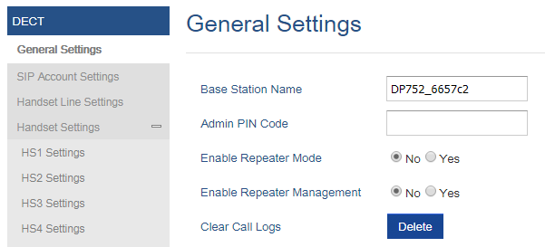
Register DP730/DP722 Handsets to DP752 Base Station
- On DP752 Base station, press and hold the Radio/Page
 button for 4 seconds until the Radio icon starts blinking to start subscription process. Or Access web UI, and press Subscribe icon
  to Open Subscription.
 - On DP730/DP722, press “Subscribe” softkey if available on the main screen or access Menu 🡪 Registration 🡪 Register while the DP752 Radio icon is blinking.
Note: “Subscribe” softkey appears only if DP730/DP722 is not registered to any DP752 base station. - Select BaseX (X=1-4) corresponding to the desired base station DP752, then press Subscribe.
- The DP730/DP722 will search for nearby base stations and will display the RFPI code and Base station name of the discovered DP752.
- Press Subscribe to pair with the displayed DP752.
- The DP730/DP722 will display Easy Pairing on the LCD and play an audible buzz when successful. Then it will return to the home screen, displaying the Handsets name and number assigned by the registered base station.
 button for 4 seconds until the Radio icon starts blinking to start subscription process. Or Access web UI, and press Subscribe icon
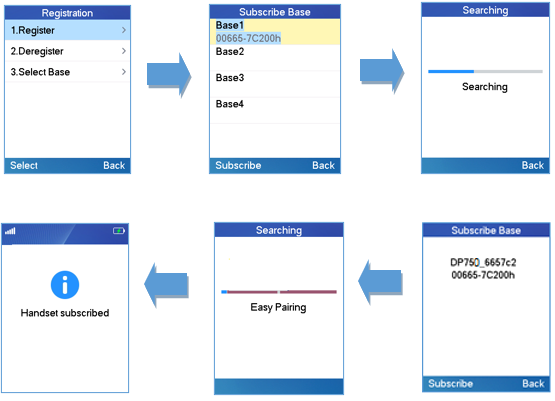
Using DP730/DP722 with Multiple DP752 Base Stations
DP730/DP722 is able to be registered to up four different DP752 base stations.
Registering DP730/DP722 to an additional DP752 base station
Considering DP730/DP722 is previously registered to an initial base station, please follow below steps to register a Handsets to an additional base station:
- Press Menu (left softkey or the selection key) to bring up operation menu.
- Use arrow keys to reach Registration.
- Select Register.
- Navigate to an unsubscribed base using arrow keys, and click on Subscribe.
- Make sure that the subscription is opened on the new base station.
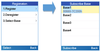
Switching Between Different Base Stations
- Press “Menu” (left softkey or the selection key) to bring up operation menu.
- Use arrow keys to reach Registration.
- Navigate to Select Base using arrow keys.
- Select the desired base station and press Select.
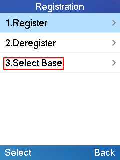
Unregister the DP730/DP722
- Using DP730/DP722 Handsets:
- On DP730/DP722, press “Menu” (left softkey or the selection key) to bring up operation menu.
- Press arrow keys to move the cursor to Registration, then press “Select” (left softkey).
- Navigate to Deregister.
- Select the Handsets to be unregistered and press “Deregister” (left softkey).
- Enter the system PIN code (default: 0000).
- Press “Done” (left softkey) to confirm or “Back” (right softkey) to cancel.
- Using DP752 Base Station UI:
- Access DP752 Web Interface.
- Go to Status 🡪 DECT Base Status.
- Locate the Handsets to unregister and press “Unsubscribe” button.
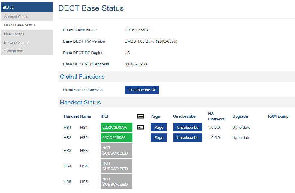
Locating DP730/DP722 Handsets from DP752 Base station
In some situations, you may have a DP730/DP722 Handsets incorrectly positioned and you don’t know its current location. You can locate a DP730/DP722 Handsets from his registered DP752 base station using below steps:
Locate via DP752 Web UI
- Access the Web GUI of your DP752 using the admin’s username and password.
- Press Login to access your settings and navigate to Status 🡪 DECT Base Status tab.
- Choose which Handsets to locate and press its corresponding Page button.
- A paging call will be received on the selected DP730/DP722 Handsets.
Note: If you press Page All icon , all registered DP730/DP722 Handsets will be receiving paging call.
 - Once located, you can press End Softkey to end paging call.
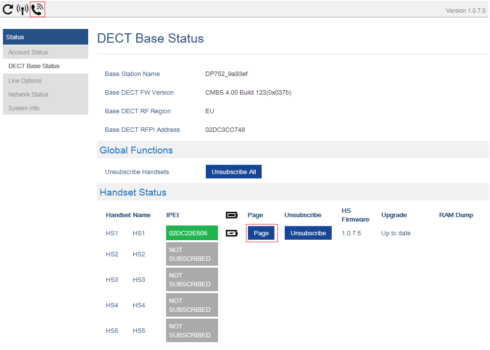
Locate via DP752 Base station
-
On DP752 Base station front side, press Radio/Page
button.
- All registered Handsets will receive Paging call.
-
Once located, you can end the paging calling by pressing any key on the Handsets or by pressing again Radio/Page
button.
 button.
 button.
Register a SIP Account
DP752 supports up to 10 SIP accounts, 5 Handsets. Each Handsets can be configured up to 10 accounts. Please be aware that line settings will be affected by DID settings (hunting group settings) in “DECT 🡪 SIP Account Settings”.
Register Account via Web User Interface
- Access the Web GUI of your DP752 using the admin’s username and password.
- Press Login to access your settings and navigate to Profiles tab and select a profile to use.
DP752 supports up to 4 profiles. A profile is a set of settings including general settings, network settings, SIP setting, audio setting, call settings and ring tones, etc.
A profile can be used with different SIP accounts. - In General Settings, set the following:
- Profile Active to Yes.
- SIP Server field with your SIP server IP address or FQDN.
- Failover SIP Server with your Failover SIP Server IP address or FQDN. Leave empty if not available.
- Prefer Primary SIP Server to No or Yes depending on your configuration. Set to No if no Failover SIP Server is defined. If “Yes”, account will register to Primary SIP Server when failover registration expires.
- Outbound Proxy with your Outbound Proxy IP Address or FQDN. Leave empty if not available.
For more information, related to above options please refer to [Profiles Page Definitions].
- Press Save and Apply to save your configuration.
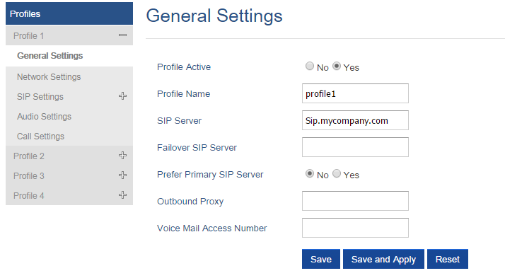
- Go to DECT 🡪SIP Account Settings
- Configure your SIP details in desired account:
- Account: Select Account row to configure (Account 1 – Account 10).
- SIP User ID: User account information, provided by VoIP service provider (ITSP). Usually in the form of digit similar to phone number or actually a phone number.
- Authenticate ID: SIP service subscriber’s Authenticate ID used for authentication. Can be identical to or different from SIP User ID.
- Password: SIP service subscriber’s account password to register to SIP server of ITSP. For security reasons, the password will field will be shown as empty.
- Name: Any name to identify this specific user.
- Profile: Select the corresponding Profile ID (1/2/3/4).
- HS Mode: Assign the account to specific Handsets (HS1, HS2…) or hunting group mode.
- Active: Set to Yes. If set to No, account is disabled and will not register.
- Press Save and Apply to save your configuration.
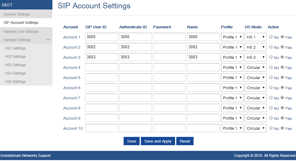
After applying your configuration, your phone will register to your SIP Server.
You can verify if your DECT phone has registered with your SIP server from your DP752 web interface under Status 🡪 Account Status (a green background with Yes under SIP Registration column for corresponding account indicates the account(s) has been successfully registered).
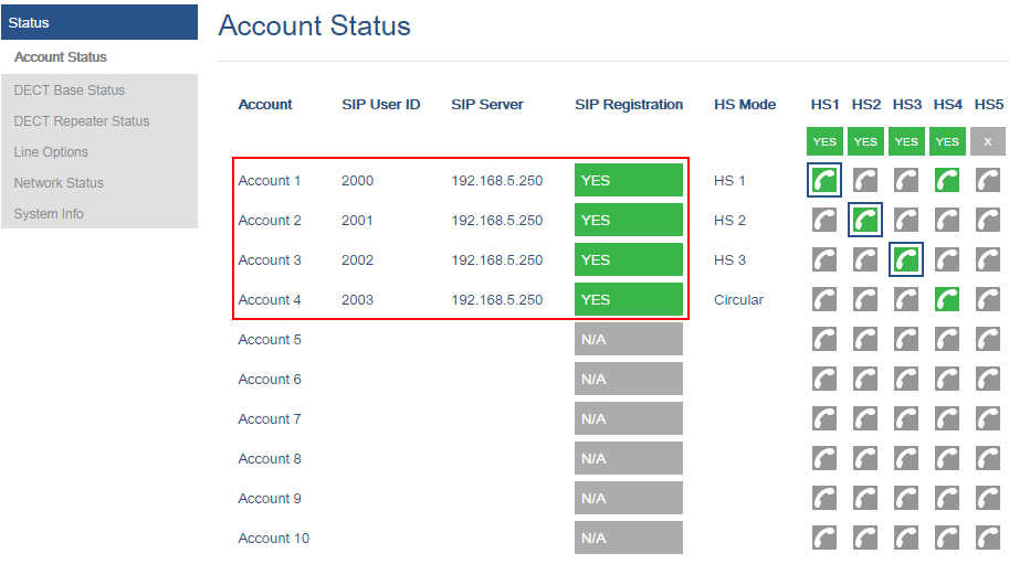
Multiple Lines and Hunting Groups
The DP752 Base Station has the ability to assign 10 lines to each registered DP730/DP722 Handsets (Up to 5 Handsets) to receive/make calls.
When a Handsets has many lines configured, users can select specific line for outgoing calls using Outgoing Default Line feature.
For incoming calls, users can choose either to redirect them to a specific Handsets or to many using Hunting Group feature so to have the same phone number and incoming calls will be distributed in a Linear, Circular or Parallel manner among the Handsets active in that Hunting Group. The number of hunting groups is limited by the number of SIP accounts registered to the base station (up to 10 accounts).
Hunting group feature is mainly used in office, warehouse and call center environments to distribute incoming calls in the best way depending on the type of hunt group.
In order to configure hunting groups for DP730/DP722 Handsets registered to the Base, users need first to register SIP accounts on DP752 Base Station SIP Account Settings and then assign accounts accordingly as lines for DP730/DP722 Handset Line Settings.
Handsets Line Settings
This section will describe how to assign lines for each DP730/DP722 Handsets for making calls.
- Access the Web GUI of your DP752 using the admin’s username and password.
- Press Login to access your settings.
- Go to DECT 🡪 Handsets Line Settings and assign to Handsets the SIP accounts already configured. Each Handsets can be configured to use up to 10 SIP accounts.
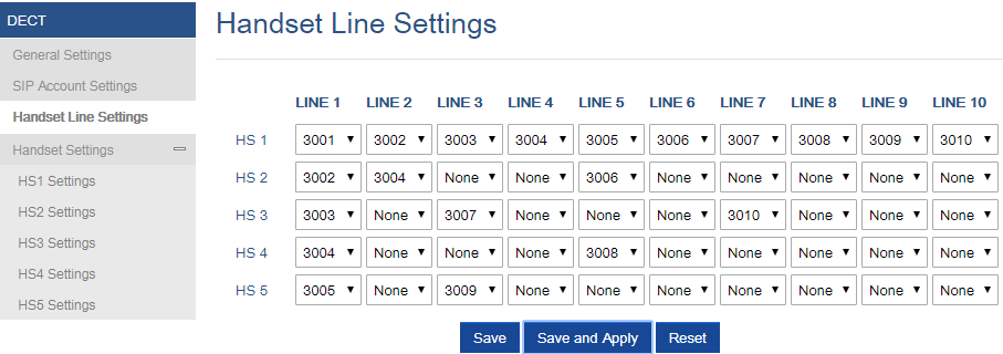
After applying your configuration, Account Status page will display the status of Handsets along with accounts status. Each column shows one HS; each row shows if the account is assigned to a HS.
For example: If the account 2, 4 and 6 are assigned to the HS2, the column of HS2 will have cells 2, 4 and 6 in green background, and account 1, 3, 5, 7, 8, 9 and 10 are in gray background. If a line is being used it will be blinking in a green / white background.
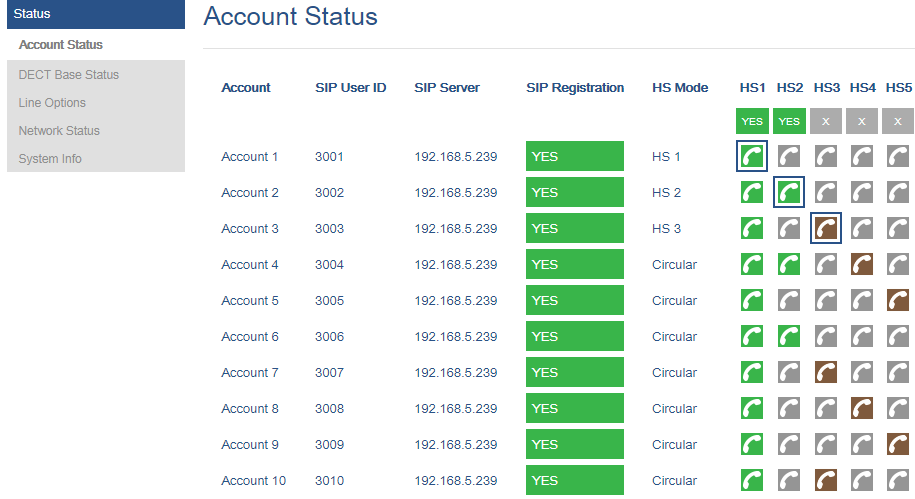
Outgoing Default Line
When a Handsets is configured with more than one line, users can change the default outgoing line on DP730/DP722 Handsets using keypad Menu 🡪 Preferences 🡪 Outgoing Default Line.
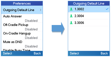
Hunting Groups
DP752 supports 3 types of hunting groups as described below:
In the examples below, we consider that all Handsets are in same hunting group and only the type of hunting group differs.
- Circular: The base station will note which Handsets answered the last call, and forward the call to the next available Handsets in round-robin fashion.
In the example below; the 1st incoming call was sent to HS1 since all Handsets were available; 2nd incoming call will be sent to HS2 since previous call was answered by HS1 and HS2 is the next available Handsets in the list; 3rd will be sent to HS4 since HS2 was the last one answering the call and HS3 is busy making an outgoing call (if HS3 was available, the call will be sent to HS3).
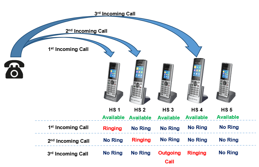
- Linear: The base station will distribute calls in predefined order from the lowest-numbered available Handsets, if no answer within ring timeout, the call will be sent to next available Handsets in sequence. This mode is also called “serial hunting”.
In the example below; all Handsets are available, the incoming call will be sent to HS1 since it’s the lowest-numbered available Handsets, if no answer within ring timeout, the call will be sent to HS2 since it’s the next available lowest-numbered Handsets, and same applies for HS3 and etc.
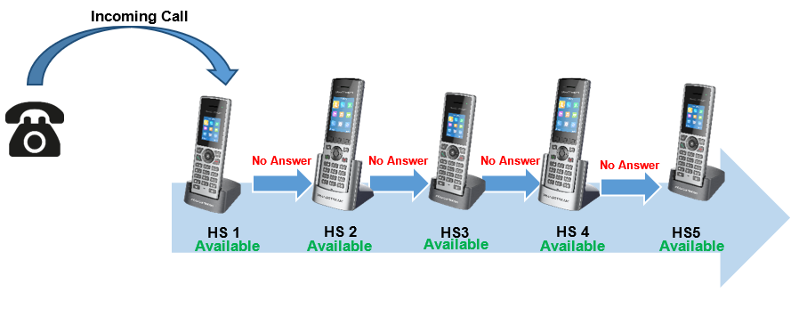
- Parallel: In this mode, all phones ring concurrently. If one phone answers, the remaining available phones can make new outgoing calls.
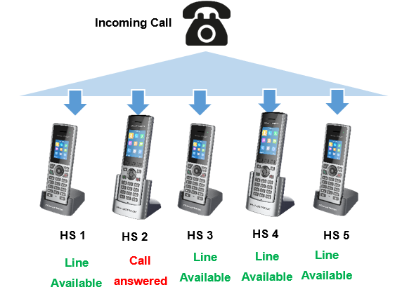
This section will describe how to configure hunting groups for incoming calls:
Below steps are considering that SIP accounts were previously registered.
- Access the Web GUI of your DP752 using the admin’s username and password.
- Press Login to access your settings.
- Go to DECT 🡪 SIP Account Settings.
- Set HS Mode depending on your needs to configure your hunting groups.
- Press Save and Apply to save your settings.
Example:
In the example below Account 2 (3003) is assigned to HS1 and HS2, and the hunting group (HS Mode) is set to Linear, so incoming calls to that account will make HS1 ringing first then if no answer within ring timeout the HS2 will start ringing.
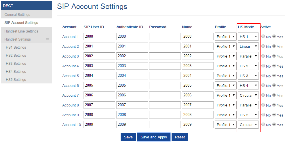
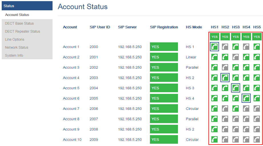
Configuration via Keypad
To configure the LCD menu using DP730/DP722’s keypad, follow the instructions below:
- Register the DP730/DP722 to DP752. Please see Register DP730/DP722 Handsets to DP752 Base Station;
- Enter/Confirm/ selection: Press the left softkey, right softkey, on-hook key or OK/Select key to enter the selected option, back to last layer or exit;
- Exit: Press “right softkey” to exit to the previous menu;
- Return to Home page: Press “On-hook” key to exit to the main menu.
- The DP730/DP722 automatically exits to main mode with an incoming call, when the phone is off hook or left idle for more than 20 seconds.
- When the phone is in idle, pressing the DOWN navigation key can enter the Outgoing call log.
Please refer to DP730/DP722 Handsets Menu Structure for more details.
Call Features
The DP752/DP730/DP722 supports traditional and advanced telephony features including caller ID, caller ID with caller Name, call forward and etc.
*30 | Block Caller ID (for all subsequent calls)
|
*31 | Send Caller ID (for all subsequent calls)
|
*67 | Call with Caller ID Blocked (per call)
|
*82 | Call with Caller ID Enabled (per call)
|
*72 | Unconditional Call Forward. To set up unconditional call forward:
|
*73 | Cancel Unconditional Call Forward. To cancel the unconditional call forward:
|
*90 | Busy Call Forward. To set up busy call forward:
|
*91 | Cancel Busy Call Forward. To cancel the busy call forward:
|
*92 | Delayed Call Forward. To set up delayed call forward:
|
*93 | Cancel Delayed Call Forward. To cancel the delayed call forward:
|
DP752 Phonebook Management
DP752/DP730/DP722 support Private and Global Phonebooks; both phonebook types can be used at same time:
Private Phonebook
Private phonebook allows you to manage your contacts on each registered Handsets; each Handsets can have his own private phonebook with his own contacts. DP752 supports up to 5 private phonebooks.
A private phonebook can be assigned to one or more Handsets registered to the base.
The following steps explain how upload your private phonebook and assign it to a specific Handsets:
- Access the Web GUI of your DP752 using the admin’s username and password.
- Press Login to access your settings and go to Phonebook 🡪 Private Phonebook Settings.
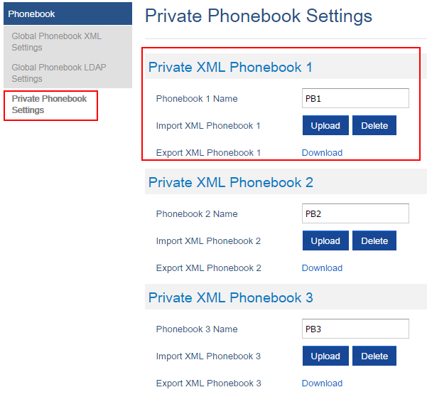
-
In Private XML Phonebook X section (X from 1 to 5):
- Enter Phonebook X Name (default value is PB1 for first Handset, PB2 for second Handset, etc.).
- Press Upload button to Import XML Phonebook X.
- Browse your computer files and select your desired phonebook.xml file.
- Press Save and Apply to save your settings.
- Go to DECT 🡪 General Settings tab.
- In Handsets Settings section, select your Handsets Phonebook to assign it to a specific Handsets as shown below where PB1 is assigned to HS1, PB2 is assigned to HS2…
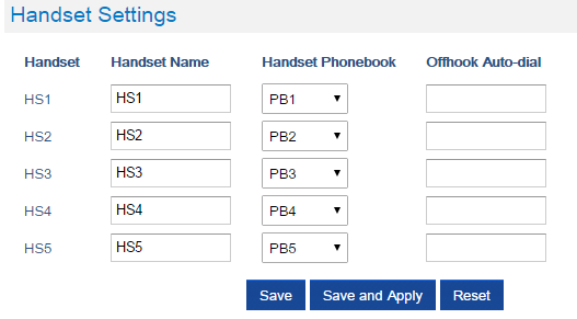
You can assign same Private Phonebook to more than one Handsets.
For example, we can assign Handsets Phonebook named PB1 to HS1 and HS2.
Any change in PB1 contacts will be applied to both HS1 and HS2 private phonebooks.
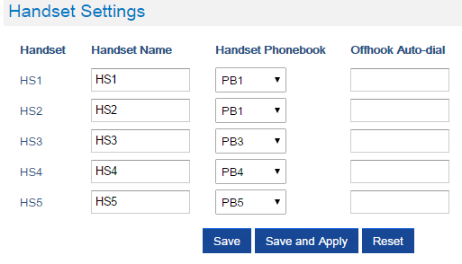
- Press Save and Apply to save your configuration.
After applying your configuration, your DP730/DP722 Handsets will display uploaded phonebook contacts. You can access your private phonebook by pressing Contacts on your DP730/DP722 Handsets. You can press Option Softkey in order to view, Create New Contact or Edit Dial if adding changes on a contact number is required before dialing.
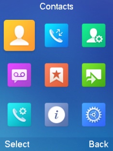
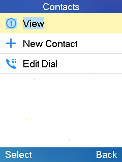
Global Phonebook
Global phonebook allows to manage contacts and use them in all registered Handsets. The contacts can be imported either via XML or via LDAP. Follow steps below to upload your shared phonebook:
Global Phonebook via XML
- Access the Web GUI of your DP752 using the admin’s username and password.
- Press Login to access your settings.
- Go to Phonebook 🡪 Global Phonebook XML Settings tab.
- Set Global Phonebook Type to XML (in this case, LDAP phonebook will not be available).

5. There are two methods to import/download your XML Phonebook:
- Automatic XML Phonebook Download
For this method, you need to use a TFTP or HTTP or HTTPS server and make your phonebook.xml file is available in your preferred server.- Set Enable Automatic XML Phonebook Download to Enabled, use TFTP/HTTP or HTTPS depending on your server.
- If using HTTP or HTTPS server and User Name and Password are required to connect to the server, set HTTP/HTTPS User Name and HTTP/HTTPS Password fields with appropriate values.
- Configure Phonebook XML Server Path field. This field could be IP address or URL, with up to 256 characters. The phone will request file named phonebook.xml from provided directory. Example: server_URL/directory
- Configure the Phonebook Download Interval (in minutes) to periodically contact your server to download new phonebook file version if available. If set to 0, automatic download will be disabled. Valid range is 5 to 720.
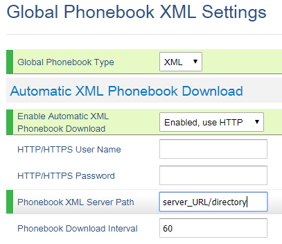
- Manual XML Phonebook Management
- Press Upload in Import XML Phonebook.
- Browse your files and select your phonebook.xml file.
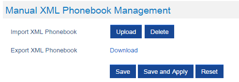
XML Phonebook file format
<?xml version="1.0" encoding="UTF-8"?>
<AddressBook>
    <Contact>
        <FirstName>First name</FirstName>
        <LastName>Last name</LastName>
        <Ringtone>Ringtone ID (default 0)</Ringtone>
        <Phone type="Home">
            <phonenumber>Home phone number</phonenumber>
        </Phone>
        <Phone type="Work">
            <phonenumber>Work phone number</phonenumber>
        </Phone>
        <Phone type="Mobile">
            <phonenumber>Mobile phone number</phonenumber>
        </Phone>
    </Contact>
</AddressBook>
| Object | Position | Type | Values | Comments |
|---|---|---|---|---|
AddressBook | Root element | Mandatory | – | Root element of the XML document |
Contact | Child element | Mandatory | – | Each contact is an entry |
LastName | Child element | At least one of them present | String | Last name of the contact |
FirstName | Child element | String | First name of the contact | |
Phone | Child element | Mandatory | – | Phone number |
PhoneNumber | Child element | At least one present | Int | Type=”Home” or Type=”Work” or Type=”Mobile” |
XML Phonebook Example:
<?xml version="1.0" encoding="UTF-8"?>
<AddressBook>
    <Contact>
        <FirstName>John</FirstName>
        <LastName>Doe</LastName>
        <Ringtone>0</Ringtone>
        <Phone type="Home">
            <phonenumber>1000</phonenumber>
        </Phone>
        <Phone type="Work">
            <phonenumber>1001</phonenumber>
        </Phone>
        <Phone type="Mobile">
            <phonenumber>1002</phonenumber>
        </Phone>
    </Contact>
    <Contact>
        <FirstName>Alice</FirstName>
        <LastName>Beck</LastName>
        <Ringtone>0</Ringtone>
        <Phone type="Home">
            <phonenumber>2000</phonenumber>
        </Phone>
        <Phone type="Work">
            <phonenumber>2001</phonenumber>
        </Phone>
        <Phone type="Mobile">
            <phonenumber>2002</phonenumber>
        </Phone>
    </Contact>
 </AddressBook>
Global Phonebook via LDAP
- Access the Web GUI of your DP752 using the admin’s username and password.
- Press Login to access your settings.
- Go to Phonebook 🡪 Global Phonebook LDAP Settings tab.
- Set Global Phonebook Type to LDAP (in this case, XML phonebook will not be available).
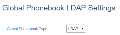
5. Under LDAP Phonebook Settings, set your LDAP parameters to connect to your LDAP server.
Refer to [Phonebook Page Definitions] for parameters explanation.
6. Press Save and Apply to save your configuration.
- Example of configuration:
LDAP protocol: LDAP
Server Address:  192.168.1.100
Port: 389
Base: dc=pbx,dc=com
User Name:
Password:
LDAP Filter: (mobile=%)(sn=%)
LDAP Version: Version 3
First Name Attribute: sn
Last Name Attribute: cn
Work Name Attribute:
Home Name Attribute:
Mobile Number Attribute: mobile
Max. Hits: 500
Search Timeout: 30
After applying your configuration, your global phonebook will be synchronized with all registered Handsets and contacts will be displayed on your DP730/DP722 Handsets screens.
DP752 ASSOCIATION WITH DP760 DECT REPEATER
Enabling Repeater Mode on DP752
Before associating the DP760 DECT Repeater to your DP752 Base Station, you should firstly enable the repeater mode on your base station. Please refer following steps to enable the repeater mode on the DP752 base station:
- Access the Web GUI of your DP752 using the admin’s username and password.
- Navigate to DECT 🡪 General Settings and set Enable Repeater Mode to Yes.
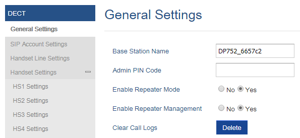
3. Press Save and Apply, then Reboot the base to apply the new settings.
DP760 DECT Repeater Association
After enabling the repeater mode on DP752 Base Station, you can easily associate it with your DP760 DECT Repeater using one of the following methods:
- Auto Association
- Manual Association
- Use DP752 Repeater Management to associate DP760
Auto Association
To auto associate your DP760 DECT Repeater with DP752 Base Station:
- Power on the DP760 DECT Repeater.
- After the DP760 finish booting, the association LED will be blinking to indicate that the repeater is searching for nearby base stations.
Note: If all the LEDs remain on, it indicates that the DP760 Repeater has successfully associated with a DP752 Base and ready for use. You may need to dissociate it before continuing (Please refer to [DP760 DECT REPEATER DISSOCIATION]). - Open subscription on your DP752 Base Station using one of following methods:
- Rebooting the Base station.
- Long press on page/subscribe button on DP752 for 4 seconds.
- Access DP752 Web GUI and press subscribe button
 .
.
- The DP760 DECT Repeater will automatically pair to DP752. Upon successful association with the DP752 Base station all LEDs will turn ON and the repeater status will be updated as following.
 button on DP752 for 4 seconds.
Manual Association
To manually associate your DP760 DECT Repeater to your DP752 Base Station:
- Access the Web GUI of your DP760 using the admin’s username and password.
- Navigate to DECT 🡪 General Settings and set Use Manually Configured RFPI to Yes.
- On Manually Configured Base RFPI field, configure your DP752 Base Station RFPI address.
Note: The RFPI Address of your DP752 Base Station is available under the Web GUI 🡪 Status 🡪 DECT Status 🡪 Base DECT RFPI Address. - Click Save and Apply to confirm the new settings.
- Open subscription on your DP752 Base Station using one of following methods:
- Rebooting the Base station
- Long press on page/subscribe button of DP752 for 7 seconds
- Access DP752 Web GUI and press subscribe button .
- The DP760 DECT Repeater will automatically pair to DP752. If the association is correctly associated, all the LEDs will remain solid on and the repeater status will be updated as following.
 button of DP752 for 7 seconds
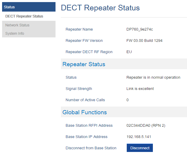
Use DP752 Repeater Management to Associate DP760
- Enabling Repeater Management Mode
The following steps illustrate how to enable and use the Repeater Management mode on DP752:
- Access the Web GUI of your DP752 using the admin’s username and password.
- Navigate to DECT 🡪 General Settings and set Enable Repeater Management to Yes.
- Press Save and Apply, then reboot the unit to apply the new settings.
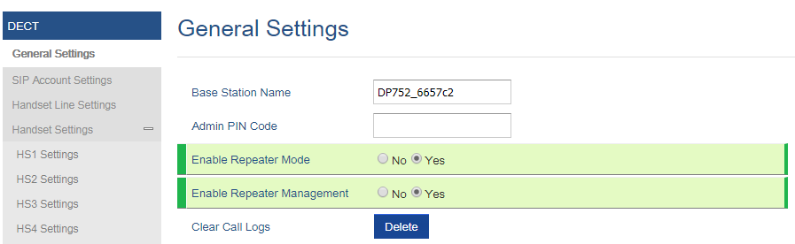
- Associating DP760 using Repeater Management Mode on DP752
The repeater management mode displays discovered and paired devices using their name, IP and Mac addresses and also gives the possibility of associating the DP752 Base Station with DP760 DECT Repeater.
Please refer to following steps in order to associate DP760 with DP752 using repeater management mode:
- Access the Web GUI of your DP752 using the admin’s username and password.
- Navigate to Status 🡪 DECT Repeater Status and select the repeater station from Discovered Devices.
- Clink Link button to associate the base and repeater stations.
Note: The DP760 Repeater stations associated with DP752 Base Station are displayed and available under Status 🡪 DECT Repeater Status 🡪 Paired Devices with their status, signal strength, number of active calls and possibility to disconnect them from the paired base station.
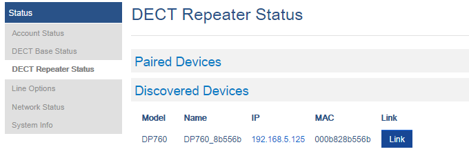
DP760 DECT REPEATER DISSOCIATION FROM DP752
To disconnect DP760 DECT Repeater from the Base Station DP752, please refer to following options:
Using DP760 Web GUI
To disconnect your DP760 DECT Repeater via Web GUI, please refer to following steps:
- Access the Web GUI of your DP760 using the admin’s username and password.
- Enter the administrator’s username and password to access the Web Configuration Menu.
- Navigate to Status 🡪 DECT Status 🡪 Global Functions and press Disconnect.
- The DP760 DECT Repeater will be automatically disconnected from the DP752 and it will start again scanning for available RFPs.
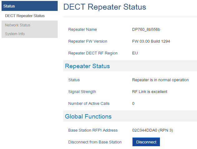
Using Page Button
Long press on page button on the back panel of DP760 for 7 seconds, it will remove the association values of the previous base station.
Using Repeater Management Mode on DP752
To disconnect your DP760 DECT Repeater using the repeater management mode on DP752:
- Access the Web GUI of your DP752 using the admin’s username and password.
- Navigate to Status 🡪 DECT Repeater Status.
- Select the repeater station from Discovered Devices.
- Clink Unlink button to dissociate the repeater from the base station.
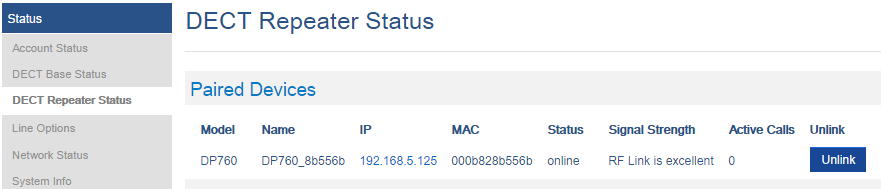
UPGRADING AND PROVISIONING
The DP752 can be upgraded via FTP/FTPS/HTTP/HTTPS by configuring the URL/IP Address for the FTP/FTPS/HTTP/HTTPS server and selecting a download method. Configure a valid URL for FTP/FTPS or HTTP/HTTPS; the server name can be FQDN or IP address.
Examples of valid URLs:
firmware.grandstream.com
fw.ipvideotalk.com/gs
DP752 Firmware Upgrade Procedure
Please follow below steps in order to upgrade the firmware version of your DP752 base station:
- Access DP752 Web GUI.
- Press Login to access your settings.
- Go to Maintenance 🡪 Firmware Upgrade page, enter the IP address or the FQDN for the upgrade server in “Firmware Server Path” field and choose to upgrade via FTP/FTPS or HTTP/HTTPS.
- Make sure to configure Firmware Upgrade and Provisioning to Always Check for New Firmware.
- Update the change by clicking the “Save and Apply” button. Then “Reboot” or power cycle the base station to update the new firmware.
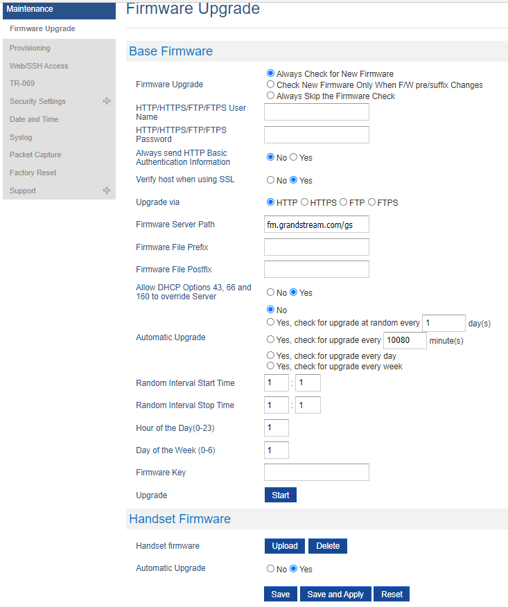
Upgrading via Local FTP/HTTP Servers
For users that would like to use remote upgrading without a local FTP/HTTP server, Grandstream offers a NAT-friendly HTTP server. This enables users to download the latest software upgrades for their devices via this server. Please refer to the webpage: http://www.grandstream.com/support/firmware
Alternatively, users can download a free FTP or HTTP server and conduct a local firmware upgrade. A free windows version FTP server is available for download from:
https://filezilla-project.org/download.php?type=server
Instructions for local firmware upgrade via FTP:
- Unzip the firmware files and put all of them in the root directory of the FTP server.
- Connect the PC running the FTP server and the phone to the same LAN segment.
- Start the FTP server and configure the FTP server in the phone’s web configuration interface.
- Configure the Firmware Server Path to the IP address of the PC.
- Configure the Admin and password authentication Credentials set on your FTP server.
- Save and apply the changes and reboot the base station.
End users can also choose to download a free HTTP server from http://httpd.apache.org/ or use Microsoft IIS web server.
Upgrading DP730/DP722 Handsets
User could upgrade their Handsets either using the LCD menu or via the Web GUI
Using the LCD menu
- On DP730/DP722, press “Menu” (left softkey or the selection key) to bring up operation menu.
- Press arrow keys to move the cursor to Settings and then press “Select”.
- Navigate to Firmware Upgrade and press “Select” (left softkey), the Handsets will upgrade the firmware available on the base station.
Using the Web GUI
- Access DP752 Web GUI.
- Press Login to access your settings.
- Go to Maintenance 🡪 Firmware Upgrade page, and enable the Automatic Upgrade option so the Handsets will upgrade the firmware automatically once it detects the new firmware.
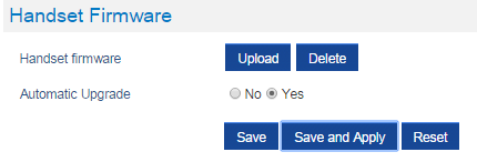
4. Update the change by clicking the “Save and Apply” button.
DP752/DP730/DP722 Provisioning
Configuration File Download
Grandstream SIP Devices can be configured via the Web Interface as well as via a Configuration File (binary or XML) through TFTP/FTP/FTPS or HTTP/HTTPS. The Config Server Path is the TFTP/FTP/FTPS or HTTP/HTTPS server path for the configuration file. It needs to be set to a valid URL, either in FQDN or IP address format. The Config Server Path can be the same or different from the Firmware Server Path.
A configuration parameter is associated with each particular field in the web configuration page. A parameter consists of a Capital letter P and 2 to 3 (Could be extended to 4 in the future) digit numeric numbers. i.e., P2 is associated with the “New Password” in the Web GUI🡪Maintenance🡪Web/SSH Access page🡪Admin Password. For a detailed parameter list, please refer to the corresponding firmware release configuration template.
The downloaded config file now will display the P value in new format, that has more meaningful name of the parameter being configured. Below is an example of how new P values looks like, please note that the old numeric P values will still be working, for example, in a single config file, the user can choose to use P values in the format of P9 or Pnetworks.static.address.ip.octet.1, or mixed format for different settings, the device will takes all of them. We are still improving the downloaded config file by adding the help text and re-ordering the settings to match the web.
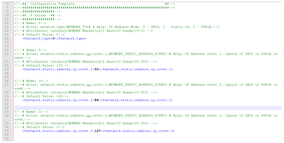
When the DP752 boots up or reboots, it will send a request to download a file named “cfgxxxxxxxxxxxx” followed by a configuration XML file named “cfgxxxxxxxxxxxx.xml”, where “xxxxxxxxxxxx” is the MAC address of the phone, i.e., “cfg000b820102ab” and “cfg000b820102ab.xml”. If the download of “cfgxxxxxxxxxxxx.xml” file is not successful, the provision program will download a generic cfg.xml file. The configuration file name should be in lower case letters.
For more details on XML provisioning, please refer to:
https://documentation.grandstream.com/knowledge-base/sip-device-provisioning-guide/
Handsets Provisioning
To configure the Handsets provisioning, please browse the base station Web GUI at Maintenance 🡪 Provisioning. This is the same page used for base station provisioning. Handsets shares the settings of base station provisioning in the field in the red rectangle, and has its own settings in the blue rectangle. After enabled Handsets Config Upgrade, need reboot the DP752 to take effect.
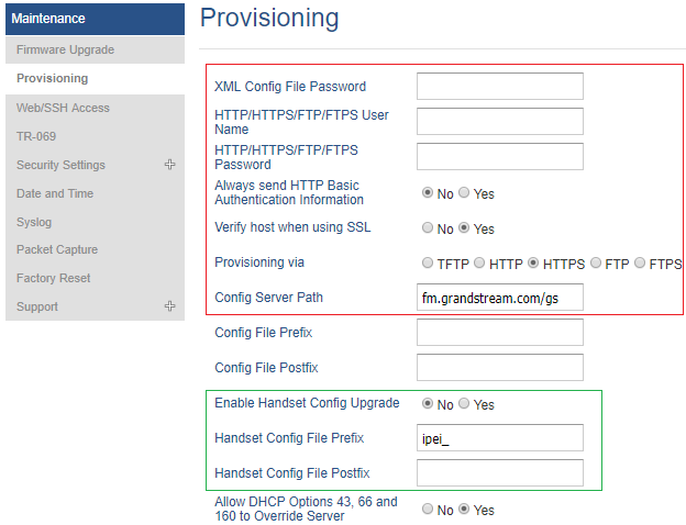
- Provisioning via: Choose the method that the base station uses to request Handsets ipei config file. Can use TFTP, FTP, FTPS, HTTP or HTTPS.
- Config Server Path: Defines the server path for provisioning. Do not prepend address with “http://” or any other protocol.
- Handset Config File Prefix: If configured, only the Handsets configuration file with the matching encrypted prefix will be downloaded and flashed into the device.
- Handset Config File Postfix: If configured, only the Handsets configuration file with the matching encrypted postfix will be downloaded and flashed into the device
When a DP730/DP722 registers to a DP752 for the first time or an already registered Handsets boots up, the DP752 will send a provisioning request for a file on the configured provisioning server, with location “Config_Server_Path/[Prefix][HS IPEI].xml[Postfix]”. For example, if Handsets’s IPEI number is 02c332b510, prefix is “ipei_”, postfix is null, and config server path is “fw.grandstream.com/gs”, the request URL is “fw.grandstream.com/gs/ipei_02c332b510.xml.
For more detailed information, please refer to Handset provisioning Guide.
RESTORE FACTORY DEFAULT SETTINGS
Resetting the DP752 Base Station
Using Hardware Button
Long press the page button
 on the device about 30 seconds, until the device reboot.
From Web Interface
- Access DP752 Web GUI.
- Navigate to Maintenance 🡪 Factory Reset.
- Select the Reset Type from the reset drop down list.
- Press Reset button and the unit will prompt a confirmation message, press OK to reset, then the unit restart automatically with parameters restored to default values or press Cancel to annul the reset.
Resetting the DP730/DP722 Handsets
Please follow the instructions below to reset the DP730/DP722 Handsets:
- Press “Menu” (left softkey or the selection key) to bring up operation menu.
- Press arrow keys to move the cursor to Settings and then press “Select”.
- Navigate to System Settings 🡪 Factory Reset, a warning window will pop out to make sure a reset is requested and confirmed;
- Press “Yes” (left softkey) to confirm and the phone will reboot.
To cancel the Reset, press “No” (right softkey) instead.
Users also can perform factory reset using combo keys on DP730/DP722 during booting up prior it’s fully booted, to give DP730/DP722 the ability to recover from some extreme cases like self-reboot or stuck right after booted up.
Please refer to following procedure for DP730/DP722 factory reset using combo key:
- Connect the USB cable and power off DP730/DP722.
- Power on DP730/DP722 and wait for Green LED.
- Press 3 times Central Key (OK/Selection Key) quickly after Green LED on.
-
Press Speaker Key
 first and then Mute Key
 after Red LED on.
- DP730/DP722 LED will start blinking in 3 colors: Green/Red if factory reset successful triggered.
- Wait for about 1-3 minutes, the DP730/DP722 will boot up with setup wizard for initial language and date format settings.
CHANGE LOG
This section documents significant changes from previous firmware versions. Only major new features or major document updates are listed here. Minor updates for corrections or editing are not documented here.
Firmware Version 1.0.21.12
- No Major changes
Firmware Version 1.0.21.10
- Added prompt to change the default password upon first login. [Web UI Access Level Management]
- Disabled non-admin account by default. [Enable User Web Access]
Firmware Version 1.0.21.6
- Added support for Action URL. [Action URL]
Firmware Version 1.0.21.4
- No Major changes
Firmware Version 1.0.21.2
- Added support to unregister SIP Instance ID only. [Instance ID]
- Added Pin for GDS to open 2nd Door [Access Password 2]
Firmware Version 1.0.19.8
- Added “Enable DND Feature” [Enable DND feature]
- Added ability to use “_” (underscore)in the SIP Server. [SIP Server]
- Enhanced security with SSL Medium Strength Cipher Suites Supported.[Enable/Disable Weak Ciphers]
- Added not failover/failback if current SBC has same priority as top choice on same SRV result. [Failback follows failback expiration timer]
- Added allow failback timer setting of 0 to disable failback mode (only necessary when using Telstra Special Feature) [Failback Expiration (m)]
Firmware Version 1.0.19.6
- Add SRTP mode “Optional” under SRTP options. [SRTP Mode]
- Added “Kandy” Special Feature mode for ITSP. [Special Feature]
Firmware Version 1.0.19.5
- Added support for “Allow SIP Reset”. [ALLOW SIP RESET]
Firmware Version 1.0.19.4
- Added ability to handle all SRV responses when using NAPTR/SRV as DNS mode for Telstra ITSP. [Special Feature]
Firmware Version 1.0.19.3
- Added support for SSL Key Log File. [WITH SECRET KEY INFORMATION]
- Added support for Alert-info in string format. [Alert Info]
Firmware Version 1.0.19.2
- Added support for XMPP connection on TR-069. [XMPP]
- Added option to use # as Redial key. [Redial key]
- Added preferred primary outbound proxy feature. [Outbound Proxy]
- Integrated new DigiCert certificates in firmware. [DigiCert certificates]
- Added new option “Follow SIP Transport to SRTP mode” to auto-switch between RTP and SRTP according to the resolved SIP transport. [Follow SIP Transport]
- Added the ability to configure F-timer and B-timer. [F-Timer] [B-Timer]
- Added support DP75x for new Cisco/BW Failover/Failback Requests. [Maximum Number of SIP Request Retries] [Failback Expiration]
- Updated the default value of “Unregister on Reboot” to “No”. [Unregister on Reboot]
- Added support for the Greek language.
Firmware Version 1.0.17.8
- No major changes.
Firmware Version 1.0.17.4
- No major changes.
Firmware Version 1.0.17.3
- Added support for Off-Hook Auto-Dial Delay. [DECT Page Definitions]
Firmware Version 1.0.17.1
- Add support to automatically reboot. [Automatic Reboot]
- Added support to allow call barging by Call-Info/Alert-Info. [Allow Barging for Auto Answer by Call-Info/Alert-Info]
- Added HW version display on device web GUI status page. [Hardware Version]
- Adjust Opus to be configured with default value 123 as the same as GRP. [OPUS Payload Type]
- No major changes.
- Added support to have a web UI option of bypass dial plan. [Bypass Dial plan]
- Add support to input provisioning server username and password on handset UI when base station is trying to download a config file from a password protected server. [User Name] [Password].
- Added support to configure Call Log settings. [Call Log]
- Added DNS SRV Failover modes. [DNS SRV Failover mode]
- Added warning tone when auto answer a call or intercom. [Play warning tone for Auto Answer Intercom]
- Added option to automatically mute after auto answer a call or intercom. [Enable Mute for Auto Answer]
- Added support to disable SIP NOTIFY authentication. [Disable SIP NOTIFY Authentication]
- Added support for Auto Timer Zone feature. [Time Zone]
- Added support to delete a paired base station from the handset.
- Added support to enable or disable “On Hold Reminder Tone” in Web UI. [On Hold Reminder Tone]
- Added support for handsets to internally page other handsets without accounts registered. [Paging]
- Added ability to configure Caller ID Display. [Caller ID Display]
- Updated the CPE to 1.0.1.141 to better support GDMS.
- No major changes.
- Added support for SNMP. [SNMP Settings]
- Added support for management interface settings that uses a virtual network interface. [Management Interface Settings]
- Added support for Broadsoft XSI phonebook. [Broadsoft XSI]
- Added support for Feature Key Synchronization that support both Broadsoft and MetaSwitch, or any server that following the same feature key synchronize standard. [Feature Key Synchronization]
- Added support for option “Backup Outbound Proxy” in all Profiles. [Backup Outbound Proxy]
- Added support for option “Use SBC” in all Profiles. [Use SBC]
- Added option to use sip or sips for SIP URI scheme when using TLS. [SIP URI Scheme When Using TLS]
- Added OpenVPN® Comp-lzo option under OpenVPN® Settings page.[OpenVPN® Comp-Izo]
- Added support to disable web UI access by adding the “Disable” option for Web Access Mode setting. [Web Access* Mode]
- Updated the CPE to better support GDMS.
- No major changes.
- Added DP75X Callee Codec Negotiation Priority option. [Callee Codec Negotiation Priority]
- Added Chile time zone. [Time Zone]
- Added support to bypass the dial plan check when redial / call back phone number via call history.[Dial Plan Bypass]
- Changed SIP account name length from 14 characters to 256. [Name]
- Added DP75X Trusted CA Certificate option for HTTPS/FTPS. [Trusted CA Certificates]
- Added support to configure customized time zone and daylight-saving time (DST) on the web UI. [Custom Time Zone Settings]
- Added support to configure Voice Mail access number on DP75X web UI. [Voice Mail Access Number]
- Increased DP75X web UI voice mail user ID character length to 30. [Voice Mail Access Number]
- Increased SIP Certificate length limitation from 2048 characters to 8192. [SIP TLS]
- Added support for FTP/FTPS User Name/Password for firmware upgrade and provisioning. [Firmware Upgrade via]
- Added support to show warning messages on handset GUI after clicking “Open” button for GDS doorbell, now it will display success or failed to indicate the result.
- Added option to enable or disable Session Timer for DP75x. [Enable Session Timer]
- Added option to enable or disable DP730 keypad backlight. [Display]
- Added support of EXTRA DEBUG level Syslog for DP75X. [Syslog Level]
- Add ability to manually configure date and time on the base Web GUI. [Manual Time Settings]
- Added support to enable or disable “Allow Unsolicited REFER” option for DP750/DP752. [Allow Unsolicited REFER]
- Change DP730 Preferences option “Mute as DND” default to “Enabled” from “Disabled” to make enabling DND more convenient. [Mute as DND]
- Added support for Intercom feature. [Shortcut]
- This is the initial version for DP752/DP730/DP722.