


Introduction to VRRP
The Virtual Router Redundancy Protocol (VRRP) is a powerful tool for ensuring network reliability and minimizing downtime. Typically deployed on egress gateway devices within a Local Area Network (LAN), VRRP creates a seamless failover mechanism by grouping multiple gateway devices into a virtual router. This virtual router serves as the default gateway for devices in the LAN, enabling uninterrupted connectivity even if one gateway device fails.
VRRP is particularly well-suited for small networks or scenarios with limited budgets, providing a cost-effective and simple solution for network redundancy.
Key Features of VRRP:
- Flexible Configuration Options: Configure VRRP protocol message parameters to suit your network’s needs.
- Load Balancing: Distribute traffic across multiple routers for improved performance and resource utilization.
- Interface Support: Configure VRRP on both WAN and VLAN interfaces to ensure comprehensive redundancy.
- Synchronization Groups: Switch the roles of a group (e.g., VLAN ↔ WAN) as a single unit for consistent failover.
- VPN Compatibility: WAN port VRRP supports synchronous switching of VPN services, ensuring secure and reliable connections.
- Multi-Vendor Support: Group VRRP-enabled devices from different manufacturers for enhanced flexibility.
- Comprehensive Logs: View detailed VRRP log information to monitor and troubleshoot your setup.
- Protocol Support: Compatible with both VRRPv2 and VRRPv3 protocols. (Note: IPv6 is not supported).
Configuring a VRRP Group
Network Topology Overview
These two network topologies illustrate two VRRP implementation scenarios: one involving a single ISP and the other utilizing dual ISPs.
VRRP with a Single ISP:
In a single ISP environment, deploying two routers configured with VRRP enhances network reliability and ensures continuous service. The primary Router 1, acting as the master VRRP router, handles all network traffic during normal operations. The secondary Router 2 remains on standby, ready to assume control automatically in the event of a hardware failure, scheduled maintenance, or unexpected outages.
This setup significantly boosts network availability by reducing potential downtime. Seamless role switching between the master and backup devices ensures uninterrupted connectivity, maintaining critical services without manual intervention. Additionally, this redundancy improves fault tolerance and adds a layer of resilience to the overall network infrastructure.

VRRP with dual ISP:
In a dual ISP setup, two routers configured with VRRP not only provide redundancy at the device level but also enhance network resilience by leveraging multiple ISP connections. Each router connects to a separate ISP, ensuring that even if one ISP experiences an outage, the network can seamlessly failover to the secondary connection.
Unlike the single ISP configuration, this setup improves both availability and performance by enabling load balancing across ISPs. The master VRRP router manages traffic distribution, while the backup router remains in standby, ready to take over in case of device failure or network disruptions. This dual-path redundancy minimizes downtime, increases fault tolerance, and ensures high availability, offering uninterrupted connectivity even during ISP-level issues.

VRRP group
To properly configure and activate a VRRP group, follow these steps:
- Navigate to GCC WebUI → VRRP page then create the VRRP group.
- Configure the following key settings:
- VRID: Set the unique Virtual Router ID for the group.
- Priority: Assign the priority level to determine the primary device.
- Deployment Interface: Select the interface where VRRP will operate.
- Virtual IP Address: Specify the shared floating IP for the group.
- Enable the VRRP group to ensure it functions as intended.
Please refer to the figures and table below for more details:


Field | Description |
VRID | Specifies the Virtual Router ID for the VRRP group. Each VRRP group must have a unique VRID, and devices within the same group must use the same VRID. A single device cannot have duplicate VRIDs. |
Enable | Enables or disables the VRRP group. Toggle this option to activate VRRP for the specified configuration. |
VRRP Name | Assigns a descriptive name to the VRRP group. If left blank, the system uses a default format: VRRP+VRID (e.g., VRRP10). |
Priority | Determines the router’s priority within the VRRP group. The router with the highest priority becomes the primary device. In case of a tie, the router with the larger interface IP address takes precedence. |
Interface | Selects the network interface where VRRP will operate. Options include Default (VLAN) for LAN redundancy and WAN for egress redundancy. Each interface can only belong to one VRRP group. |
Virtual IP | The Virtual IP (VIP) must be in the same subnet as the deployment interface but cannot match the interface’s assigned IP. For VLAN interfaces, the VIP should be the default gateway for devices in the VLAN, ensuring seamless failover. |
Track Interface | Monitors the status of uplink interfaces (e.g., WAN). If all tracked interfaces are down, the router relinquishes its primary role. |
Advanced Settings | |
Preemption Mode | Allows a backup router with a higher priority to preempt the current primary router. |
Preemption Delay (seconds) | Specifies the time (default: 1 second) to wait before initiating preemption. This minimizes disruptions caused by transient network issues. |
Notification Interval (seconds) | Sets the frequency at which the primary router sends VRRP advertisements. All routers in the VRRP group must use the same interval to ensure proper synchronization. |
VRRP Versions | Configures the VRRP version: VRRPv2 supports IPv4 networks, while VRRPv3 supports both IPv4 and IPv6. Note: IPv6 is currently not supported. |
Plaintext Authentication | Enables authentication to secure VRRP communication and prevent unauthorized devices from joining the group. Both primary and backup devices must use the same authentication string. Only supported in VRRPv2. |
Add/Edit VRRP Group
GCC 1: Primary: create two VRRP Groups, one for LAN and another one for WAN with high priority.

GCC 2: Secondary: create two VRRP Groups, one for LAN and another one for WAN with lower priority.

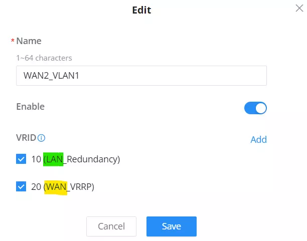
VRRP Synchronization Group
A VRRP synchronization group ensures that all VRRP instances within the group maintain synchronized states. If one instance changes its role, the other instances in the group automatically transition to the same role.
When VLAN and WAN interfaces are part of a synchronization group, policy routing must be implemented in conjunction to ensure proper functionality.
To add Sync Group, Navigate to VRRP → Sync Group then click on the “Add” button as shown below:

Select the VRRP Groups (WAN/LAN) combination.
VRRP Logs
VRRP logs capture events and status changes during the operation of VRRP instances. They provide critical insights for monitoring instance behavior, diagnosing issues, and troubleshooting effectively.

Examples Using Two GCC Devices (Same Vendor)
Below are scenarios demonstrating the effective use of two Grandstream GCC devices, showcasing their combined capabilities and benefits.
Single ISP Usage Scenario
In a single ISP environment, two GCC devices can be deployed using VRRP to ensure network reliability. One device functions as the master VRRP router, managing traffic under normal conditions, while the second serves as a backup, ready to take over in case of failure or maintenance.
This configuration provides high availability and minimizes downtime, ensuring uninterrupted connectivity through seamless role-switching between the devices.
Network Topology (Single ISP)

In the topology shown, GCC1 is initially configured as the Primary router, while GCC2 serves as the Secondary. The ISP has allocated a public network segment of 45.78.56.0/29. After enabling VRRP on the WAN interface, intranet services can be accessed via the virtual IP address 45.78.56.4. On the internal LAN, the gateway IP is configured as 192.168.80.254.
Initial State
GCC1, as the Primary node, handles both intranet access and internet connectivity. If GCC1 experiences a failure (such as a system freeze, power outage, or LAN port disconnection), GCC2 automatically assumes the Primary role. This ensures continued access to both the intranet and the Internet without interruption.
Virtual IP Address Management
- Intranet Gateway: The gateway IP (192.168.80.254) is only active on the Primary router. This IP is exclusive to either GCC1 or GCC2, depending on the active Primary role.
- External Network Access: Similarly, the virtual WAN IP (45.78.56.4) is assigned only to the active Primary router.
Failover Process
When GCC1 fails, VRRP seamlessly transfers the virtual WAN IP and virtual VLAN gateway IP to GCC2. A gratuitous ARP is broadcast to refresh the ARP table on the connected switch, enabling the switch to forward traffic to GCC2. This transition from Secondary to Primary is virtually transparent, ensuring clients and the ISP experience no service disruptions due to unchanged IP addresses.
Notes:
- WAN VRRP Considerations: If the ISP provides fewer than three IP addresses, enabling VRRP on the WAN interface is not recommended.
- Switch Configuration:
- Both routers’ WAN interfaces must be connected to the same switch, and their VLAN interfaces should also be connected to the same switch for proper communication. Please refer to the topology above.
- If the switch has Spanning Tree Protocol (STP) enabled to prevent loops, the ports may not immediately enter the forwarding state. This delay can influence the VRRP role election process, potentially affecting failover performance.
GCC1 Configuration (Single ISP)
- Add WAN VRRP Group
To configure WAN VRRP, create a VRRP group and select WAN1 as the deployment interface. Ensure the following parameters match the settings on the WAN_VRRP interface of the GCC2 router: VRID, Virtual IP, Preemption Mode, VRRP Version, and plaintext authentication. Set the WAN_VRRP priority for GCC1 to 100 and for GCC2 to 80. With this configuration, GCC1 will assume the Primary role for WAN_VRRP.
To begin the configuration, navigate to Networking → VRRP → Add VRRP Group.

- Add VLAN VRRP Group
To configure VLAN VRRP, create a VRRP group and select any VLAN as the deployment interface. Ensure that the following parameters match the VLAN_VRRP configuration on the GCC2 router: VRID, Virtual IP, Preemption Mode, VRRP Version, and plaintext authentication. Set the VLAN_VRRP priority of GCC1 to 100 and GCC2 to 80, making GCC1 the Primary for VLAN VRRP.
Additionally, configure the Track Interface to WAN1 to enable automatic role switching between Primary and Secondary in the event of a failure on the uplink interface of the Primary device, preventing service disruption.
To begin the configuration, navigate to Networking → VRRP → VRRP Group.

- Configuring a VRRP Synchronization Group
To ensure seamless failover, the WAN and LAN interfaces should be synchronized. Add both the WAN and VLAN interfaces on the router to the same synchronization group. When one interface switches roles, the other will automatically follow, ensuring consistent performance.
To configure the synchronization group, navigate to Networking → VRRP → Sync Group.

To configure VLAN port settings, navigate to Networking → Network Settings → LAN.

- Modify VLAN gateway address
If the DHCP service is enabled for the corresponding VLAN, users can change the gateway address to a virtual IP address, such as 192.168.80.254.
For clients with static IP configurations, users can manually set the gateway to the specified virtual IP address.
To configure the VLAN gateway, navigate to Networking → Network Settings → LAN.

- Configuring Policy Routing
The load balancing policy pool is a configuration used to implement load balancing and failover across multiple WAN ports, which will be referenced in policy routing. Users can select the appropriate policy mode based on their requirements: Load Balancing or Backup Mode.
- Load Balancing: Traffic is distributed across interfaces in proportion to the set load balancing weights. Ensure weights are allocated based on actual bandwidth to optimize performance.
- Backup Mode: In this mode, when the preferred interface fails, traffic will automatically switch to the backup interface. Both interfaces can share traffic based on the load balancing weights to ensure uninterrupted network connectivity.
In this configuration, Backup Mode is selected. By default, VLAN traffic will route through the WAN1 VRRP interface. If the WAN1 VRRP interface fails, traffic will be directed to the WAN1 interface.
To view or configure policy routes, navigate to Networking → Routing → Policy Routes.


- Configure VPN
After setting up WAN VRRP, users can select the WAN VRRP interface for VPN configuration.
For example, when configuring an OpenVPN® server, select the interface as WAN1 (WAN VRRP). In this case, the WAN1 VRRP interface on the GCC1 device will be active, and the OpenVPN® server service will be supported by the GCC1 device.
To configure the OpenVPN® server, navigate to Networking → VPN → OpenVPN®:


- Configure port forwarding
External network users can access internal web services via the virtual IP 45.78.56.4 on the GCC device.
Configure the port forwarding function on both GCC1 and GCC2. External users will be able to access the web page of the PC (192.168.80.213) in VLAN 80 by using the URL: http://45.78.56.4:10000.
To configure port forwarding, navigate to Networking → External Access → Port Forwarding:

- Configuring Firewall Rules
Users can configure firewall rules for the WAN_VRRP interface based on specific requirements.
For example, when configuring forwarding rules, both GCC1 and GCC2 devices should define forwarding rules where the Source Group is set to the WAN VRRP interface, the Destination Group is set to the VLAN where the PC is located, and the Destination IP Address is the accessible IP (e.g., 192.168.80.213). This configuration allows external users to access the web page hosted on the PC in the internal subnet.
To configure forwarding rules, navigate to Firewall → Firewall Policy → Traffic Rules.

GCC2 Configuration (Single ISP)
- Add WAN VRRP Group
Set the WAN_VRRP priority of GCC1 to 100 and the WAN_VRRP priority of GCC2 to 80. GCC2 WAN_VRRP will become Secondary.
To configure WAN VRRP, please navigate to Networking → VRRP → VRRP Group:

- Add VLAN VRRP Group
Set the VLAN_VRRP priority of GCC1 to 100 and the VLAN_VRRP priority of GCC2 to 80. GCC2 VLAN_VRRP will become Secondary.
To configure VLAN VRRP, please navigate to Networking → VRRP → VRRP Group:

The rest of the steps are similar to the GCC 1 configuration.
Dual ISP usage scenario
Network Topology (Dual ISP)
In this topology, we have now two ISPs with different IP segments as shown below:

GCC1 is initially configured as the Primary router, and GCC2 is the Secondary. Two ISPs provide separate network segments: 45.78.56.0/29 and 104.245.96.0/29, both of which can independently access the Internet. The internal LAN uses 192.168.80.254 as the gateway IP.
Failover and Role Switching
- Initial State: GCC1, as the Primary, handles all network services.
- ISP Failover: If one of GCC1’s ISP services fails, the WAN port failover feature automatically switches to the other WAN port for continued Internet access.
- Device Failover: If both ISP connections on GCC1 fail, or if GCC1 encounters hardware issues (e.g., freeze, power outage, or LAN port failure), VRRP triggers a role switch, promoting GCC2 to the Primary role to continue providing network services.
Notes:
- WAN VRRP Considerations: When using dual WAN, it is recommended to rely on the WAN failover feature for network switching rather than enabling the WAN VRRP feature.
- Independent ISP Access: Both ISP-provided IP ranges can access the Internet independently.
- Switch Configuration:
- VLANs of both routers must connect to the same switch.
- WAN ports on both routers should be configured to match the settings required by each ISP, including VPN, policy routing, and port forwarding.
- STP Impact: If the switch uses the Spanning Tree Protocol (STP) to prevent loops, its ports may take time to enter the forwarding state, potentially delaying VRRP role elections.
GCC1 Configuration (Dual ISP)
- Add VLAN VRRP Group
- Add a VRRP group and select a VLAN as the deployment interface.
- Ensure that the following settings match those configured on the VLAN_VRRP interface of GCC2:
- VRID
- Virtual IP
- Preemption Mode
- VRRP Version
- Plaintext Authentication
- Set the VLAN_VRRP priority for GCC1 to 100 (Primary) and for GCC2 to 80 (Secondary).
- Configure the Track Interface to monitor WAN1 and WAN2 to ensure seamless role switching. If both uplink interfaces on the Primary fail, the VLAN VRRP role will switch to the Secondary, avoiding any service disruption.
To configure VLAN VRRP, navigate to Networking → VRRP → VRRP Group:

- Modify VLAN gateway address: Please refer to the steps mentioned above.
- Configuring Policy Routing
In this scenario, select Backup Mode. Default VLAN traffic will initially pass through the WAN1 interface. If the WAN1 interface becomes unavailable, the traffic will automatically switch to the WAN2 interface, maintaining uninterrupted connectivity.
To configure policy routes, navigate to Networking → Routing → Policy Routes.


GCC2 Configuration (Dual ISP)
- Add VLAN VRRP Group
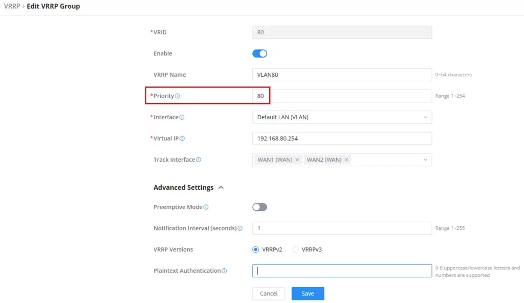
The VLAN_VRRP priority is configured with GCC1 set to 100 (Primary) and GCC2 set to 80 (Secondary). This setup ensures that GCC2 operates as the Secondary. Additionally, the Track Interface can be configured to monitor WAN1 and WAN2. This allows for seamless role switching of the VLAN VRRP in the event of a complete failure of the uplink interfaces on the Primary device, effectively preventing service interruptions.
To configure VLAN VRRP, go to Networking → VRRP → VRRP Group:
- Modify VLAN gateway address: Please refer to the steps mentioned above.
- Configuring Policy Routing: same steps as GCC1.
Examples with Different Vendors
Single ISP Scenario
Network Topology – Different Vendor (Single ISP)

As shown in the topology above, GCC is initially configured as the Primary router, and the Other Router as the Secondary. The ISP allocates the network segment 45.78.56.0/29, with IPs 45.78.56.2 and 45.78.56.3 assigned to the WAN ports of each router, respectively. The internal LAN gateway IP is set to 192.168.80.254.
In the event of a failure on GCC, such as a device freeze, power outage, or LAN port unavailability, the Other Router will automatically take over as the Primary and continue to provide network services.
GCC Configuration – Single ISP
- Add VLAN VRRP Group
Any VLAN interface can be used as the deployment interface. Ensure that the VRID, Virtual IP, Preemption Mode, VRRP Version, and Plaintext Authentication settings match those of the other routers. The device with the higher priority will automatically assume the primary role. Additionally, users can configure the Track Interface to WAN1 to enable automatic switching of the VLAN VRRP primary-slave role if the primary device’s uplink interface fails, preventing service disruption.
To configure VLAN VRRP, navigate to Networking → VRRP → VRRP Group.

- Modify VLAN Gateway Address
If the DHCP service is enabled for the corresponding VLAN, users can change the gateway address to a virtual IP address, such as 192.168.80.254.
For clients with static IP configurations, users can manually set the gateway to the specified virtual IP address.
To configure the VLAN gateway, navigate to Networking → Network Settings → LAN.

Dual ISP Scenario
Network Topology – Different Vendor (Dual ISP)

As shown in the topology above, GCC is initially set as the Primary router, while the Other Router serves as the Secondary. Two ISPs are assigned separate network segments: 45.78.56.0/29 and 104.245.96.0/29, with each segment having independent Internet access. The gateway IP for the internal LAN is 192.168.80.254.
Initially, GCC handles network services as the Primary router. If one of GCC’s ISP services fails, the WAN port failover feature will activate, switching to the backup WAN port to maintain Internet access. If both ISP services of GCC fail, a role switch occurs, making the Other Router the Primary, ensuring continued network services. Similarly, if GCC experiences a device freeze, power outage, or LAN port failure, the Other Router will automatically assume the Primary role and continue providing services.
GCC Configuration – Dual ISP
- Add VLAN VRRP Group
To configure VLAN VRRP, select any VLAN as the deployment interface and ensure the VRID, Virtual IP, Preemption Mode, VRRP Version, and Plaintext Authentication settings match those of the other routers. The device with the highest priority will assume the primary role. Additionally, set the Track Interface to WAN1 and WAN2 to ensure that the VLAN VRRP primary and secondary roles switch if the uplink interface of the primary device fails completely, preventing service interruptions.
To configure VLAN VRRP, please navigate to Networking → VRRP → VRRP Group:

- Modify VLAN Gateway Address
If the DHCP service is enabled for the corresponding VLAN, users can change the gateway address to a virtual IP address, such as 192.168.80.254.
For clients with static IP configurations, users can manually set the gateway to the specified virtual IP address.
To configure the VLAN gateway, navigate to Networking → Network Settings → LAN.

- Configure Policy Routing
In this scenario, select Backup Mode. Default VLAN traffic will initially pass through the WAN1 interface. If the WAN1 interface becomes unavailable, the traffic will automatically switch to the WAN2 interface, maintaining uninterrupted connectivity.
To configure policy routes, navigate to Networking → Routing → Policy Routes.

Then, apply the created Load Balance rule to the Source Group, in our case, it’s the Default VLAN.

Example Using Three GCCs and a Single ISP (Direct Connection)
This section covers configuring a three-GCC setup consisting of two GCC devices running VRRP and one additional GCC acting as a dual-WAN CPE positioned behind them. All three GCC units are directly connected to each other with no switch in between, ensuring that VRRP heartbeats, failover communication, and upstream routing occur smoothly in this direct-link topology.
Please refer to the set up below that will be configured:

GCC1 Configuration
Add WAN VRRP – GCC1
Add a VRRP group, select WAN (the connected interface) as the deployment interface, and ensure that the VRID, Virtual IP, Preemption Mode, VRRP Version, and Simple Text Authentication parameters are the same as those configured on the WAN_VRRP interface of the GCC2 router. Also, set the priority of GCC1’s WAN_VRRP to be higher than that of GCC2’s WAN_VRRP, and GCC1’s WAN_VRRP will become the Primary. You can also enable preemption mode.
To configure WAN VRRP, please navigate to Networking → VRRP → VRRP Group:
- Set the VRID to 50, this identifies the VRRP group. All routers in the same group must use the same VRID.
- Enable the VRRP group by toggling the Enable switch on, to activate VRRP on this interface so it can participate in Master/Backup selection.
- Enter WAN_pri as the VRRP Name.
- Set the Priority to 45, this determines the likelihood of becoming the VRRP Master. Higher numbers = higher priority.
- Select WAN2 (WAN) as the Interface for VRRP.
- Enter 192.168.88.164 as the Virtual IP. The shared gateway IP used by devices on the network. The Master router will respond to this IP.
- Leave Track Interface unselected (no tracking interface configured).

Some additional advanced settings:
- Enable Preemptive Mode: Allows this router to reclaim the Master role if it has a higher priority.
- Set Preemption Delay to 1 second: Waits 1 second before taking over as Master when preemption occurs.
- Set Notification Interval to 1 second: Sends VRRP advertisements every 1 second to maintain group status.
- Select VRRPv2 as the VRRP Version: Chooses the VRRP protocol version compatible with the deployment.
- Leave Plaintext Authentication blank: No authentication password is used for VRRP messages.
Add VLAN VRRP – GCC1
Add a VRRP group, select the VLAN where the downstream router is located for the deployment interface, and ensure that the VRID, Virtual IP, Preemption Mode, VRRP Version, and Simple Text Authentication parameters are the same as those of GCC2. Also, set the priority of GCC1 to be higher than that of GCC2, making GCC1 the master device; at the same time, you can enable the preemption mode.
To configure VLAN VRRP, please navigate to Networking → VRRP → VRRP Group:
- Set the VRID to 20: This is the Virtual Router ID for the LAN-side VRRP group. All routers participating in this LAN VRRP must use the same VRID.
- Enable the VRRP group: Activates VRRP on the LAN interface so the device can function as Master or Backup.
- Enter “LAN_pri” as the VRRP Name: A friendly label used to identify this VRRP instance for the LAN side.
- Set the Priority to 35: Determines which router becomes the LAN-side VRRP Master. Higher number = higher priority.
- Select “Default (VLAN)” as the Interface: This defines the interface VRRP will operate on, in this case the default LAN/VLAN interface.
- Enter “192.168.80.145” as the Virtual IP
- This is the shared LAN gateway IP used by downstream devices.
- The router acting as Master will respond to this IP.
- Leave Track Interface unselected: No specific interface tracking is applied for VRRP failover logic.

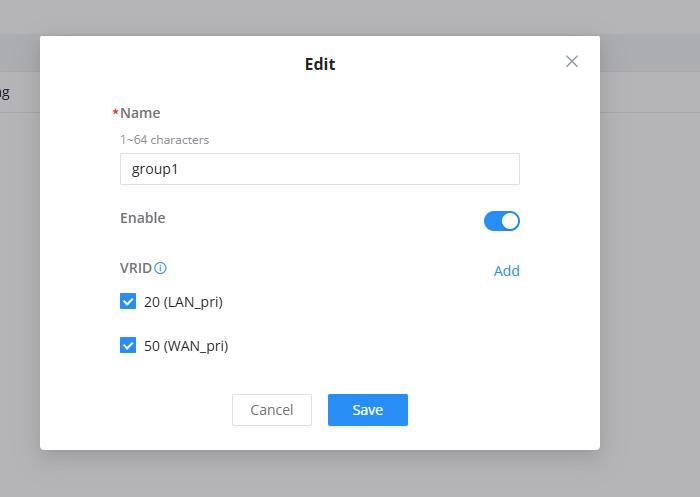
Configure VRRP synchronization group
Switching between WAN and LAN requires synchronization. By putting the WAN and VLAN on the router into the same group, when one switches roles, the other will also switch synchronously.
To configure VLAN VRRP, please navigate to Networking → VRRP → Synchronization Group:
- Enter “group1” as the Name: This is the label for the synchronization group. It helps you identify which VRRP instances are tied together.
- Enable the Synchronization Group: Activates the sync feature so the selected VRRP groups will switch roles together.
- Select VRID 20 (LAN_pri)
- Adds the LAN-side VRRP group to the synchronization group.
- This ensures the LAN VRRP instance will follow role changes applied to the WAN VRRP.
- Select VRID 50 (WAN_pri)
- Adds the WAN-side VRRP group to the same synchronization group.
- When the WAN VRRP instance switches between Master/Backup, the LAN VRRP will switch in sync.
- Click Save to apply the settings: Finalizes the synchronization group configuration, linking both VRRP instances for coordinated failover.
Modify VLAN Gateway Address
You need to change the gateway address to the virtual IP address, for example: 192.168.80.145;
To configure VLAN, please navigate to Networking → Network Settings → LAN:
- Set VLAN ID to 1: identifies the VLAN. VLAN 1 is typically the default LAN network.
- Enter “Default” as the VLAN Name: Provides a clear label for this VLAN configuration.
- Set Forwarding Destination Group to “All”: Allows VLAN traffic to be forwarded to all destination groups configured on the device.
- Keep Captive Portal Disabled: No client authentication or redirection is applied to this VLAN.
- Turn off VLAN Port IPv4 Address: The VLAN interface will not use separate per-port IP addressing.
- Set the IPv4 Address to 192.168.80.146: This is the LAN-side IP address of the router inside this VLAN.
- Set Subnet Mask to 255.255.255.240: Defines a /28 network, supporting IPs from 192.168.80.144 to 192.168.80.159.
- Enable DHCP Service: Allows the router to hand out IP addresses automatically to LAN clients.
- Set the Gateway Address to 192.168.80.145: This is the VRRP Virtual IP and must be used as the default gateway by all devices.
- Configure the DHCP Address Range: 192.168.80.148 – 192.168.80.158: Defines the pool of IP addresses that will be assigned to clients.
- Set DHCP Lease Time to 120 minutes: Specifies the duration clients keep their assigned IP before renewal.
- Leave DHCP Option fields empty: No additional DHCP options (DNS, NTP, custom values) are being configured.

GCC2 Configuration
Add WAN VRRP – GCC2
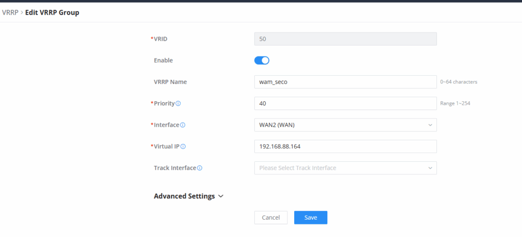
Add a VRRP group, select WAN (the connected interface) as the deployment interface, and ensure that the VRID, Virtual IP, Preemption Mode, VRRP Version, and Simple Text Authentication parameters are the same as those configured on the WAN_VRRP interface of the GCC1 router. Also, set the priority of WAN_VRRP of GCC2 to be lower than that of WAN_VRRP of GCC1, and GCC2 WAN_VRRP will become Secondary.
To configure WAN VRRP, please navigate to Networking → VRRP → VRRP Group:
- Set the VRID to 50: This VRRP group uses the same VRID as the Primary WAN on the other GCC, meaning both devices belong to the same failover group.
- Enable the VRRP group: Activates VRRP on this interface so the router can operate as Master or Backup.
- Enter “wan_seco” as the VRRP Name: Identifies this VRRP instance as the Secondary WAN role.
- Set the Priority to 40: Lower than the Primary device’s priority (45), ensuring this router becomes the Backup in the VRRP group.
- Select “WAN2 (WAN)” as the Interface: Specifies the WAN interface where this VRRP instance operates.
- Set the Virtual IP to 192.168.88.164:
- This is the shared VRRP Virtual IP for the WAN side.
- Only the active Master router responds to this IP.
- Leave Track Interface unconfigured: No track interface is selected for conditional failover logic.
Add LAN VRRP – GCC2
Add a VRRP group, select the VLAN where the downstream router is located for the deployment interface, and ensure that the VRID, Virtual IP, Preemption Mode, VRRP Version and Simple Text Authentication parameters are the same as those of GCC1. Also, set the priority of GCC2 to be lower than that of GCC1, and GCC2 VLAN_VRRP will become Secondary.
To configure VLAN VRRP, please navigate to Networking → VRRP → VRRP Group:
- Set the VRID to 20: This VRRP LAN group uses the same VRID as the Primary’s LAN VRRP, ensuring both devices participate in the same LAN failover group.
- Enable the VRRP group: Activates VRRP on the LAN interface so this device can serve as a Backup router.
- Enter “lan_seco” as the VRRP Name: Identifies this LAN VRRP instance as the Secondary role.
- Set the Priority to 30: Lower than the Primary router’s LAN priority (35), ensuring this router becomes the Backup on the LAN side.
- Select “Default (VLAN)” as the Interface: Indicates that VRRP will operate on the default LAN/VLAN interface.
- Set the Virtual IP to 192.168.80.145
- This shared VRRP Virtual IP is used by all LAN clients as their default gateway.
- Only the VRRP Master responds to this IP.
- Leave Track Interface unconfigured: No interface tracking is being used for dynamic failover triggers.

Configure VRRP Synchronization Group – GCC2
Switching between WAN and LAN requires synchronization. By putting the WAN and VLAN on the router into the same group, when one switches roles, the other will also switch synchronously.
To configure VLAN VRRP, please navigate to Networking → VRRP → Synchronization Group:
- Enter “gg2” as the Sync Group Name: This label identifies the synchronization group used on the secondary GCC device.
- Enable the Sync Group: Activates synchronization so that both WAN and LAN VRRP instances switch roles together.
- Select VRID 20 (lan_seco)
- Adds the LAN VRRP group of the secondary device to the sync group.
- Ensures LAN failover always matches the WAN failover state.
- Select VRID 50 (wam_seco)
- Adds the WAN VRRP group of the secondary device to the same sync group.
- Links both VRRP instances so their Master/Backup states remain synchronized.
- Click Save to apply the configuration: Finalizes the sync group setup and enables coordinated failover between WAN and LAN VRRP groups.

Modify VLAN gateway address – GCC2
You would need to change the gateway address to the virtual IP address , for example: 192.168.80.145 ;
To configure VLAN, please navigate to Networking → Network Settings → LAN :
- Set VLAN ID to 1: Identifies this VLAN; VLAN 1 is typically the default LAN network.
- Enter “Default” as the VLAN Name: A simple label describing the main LAN VLAN.
- Set Forwarding Destination Group to “All”: Allows this VLAN to forward traffic to all configured destination groups.
- Keep Captive Portal Disabled: No authentication or redirection portal is applied to devices on this VLAN.
- Disable VLAN Port IPv4 Address
- Set the IPv4 Address to 192.168.80.147
- This is the LAN IP address for this GCC on VLAN 1.
- It must be within the same subnet as the VRRP Virtual IP.
- Set Subnet Mask to 255.255.255.240: Creates a /28 subnet covering the range 192.168.80.144 to 192.168.80.159.
- Enable DHCP Service: Allows the GCC to automatically assign IP addresses to connected LAN clients.
- Set the Gateway Address to 192.168.80.145: This is the VRRP Virtual IP used by all devices on the LAN as their default gateway.
- Set the DHCP Allocation Range to 192.168.80.148 – 192.168.80.158: Defines the pool of IP addresses available for DHCP clients.
- Set DHCP Lease Time to 120 minutes: Specifies how long clients retain their assigned IP before renewal.
- Leave DHCP Option fields empty: No custom DHCP options (DNS, NTP, vendor configurations) are applied.

GCC3 Configuration
Configure dual WAN
GCC3 operates as a dual-WAN downstream router and is not part of the VRRP group. Its two WAN ports are connected to the LAN ports of GCC1 and GCC2, respectively. Traffic originating from GCC3’s LAN network will be balanced across both WAN interfaces and will ultimately exit through the upstream GCC that is currently the VRRP master, this ensures redundancy and continuous connectivity.

© Copyright 2024 OpenVPN | OpenVPN is a registered trademark of OpenVPN, Inc.