HA INTRODUCTION
The High Availability feature on the Grandstream GCC series provides enterprises with a reliable solution for PBX redundancy and failover support. In the HA setup, there are two GCC PBXs with one PBX in the “active” role and the other in the “standby” role. The two GCCs must have the same model and the same firmware version. The data on the active GCC PBX will be synchronized to the standby GCC PBX in a real-time manner and the standby GCC PBX monitors the active GCC PBX’s running status regularly. When the active GCC PBX runs into hardware or critical software issues, the standby GCC PBX will take over immediately and become the active server. HA feature supports automatic call recovery for UDP point-to-point calls and conference calls, allowing enterprises to communicate and collaborate without the hassle of service interruption.
TOPOLOGY
Take the following topology as an example (for more scenarios and configurations, please refer to the GCC6000 Series VRRP User Guide):
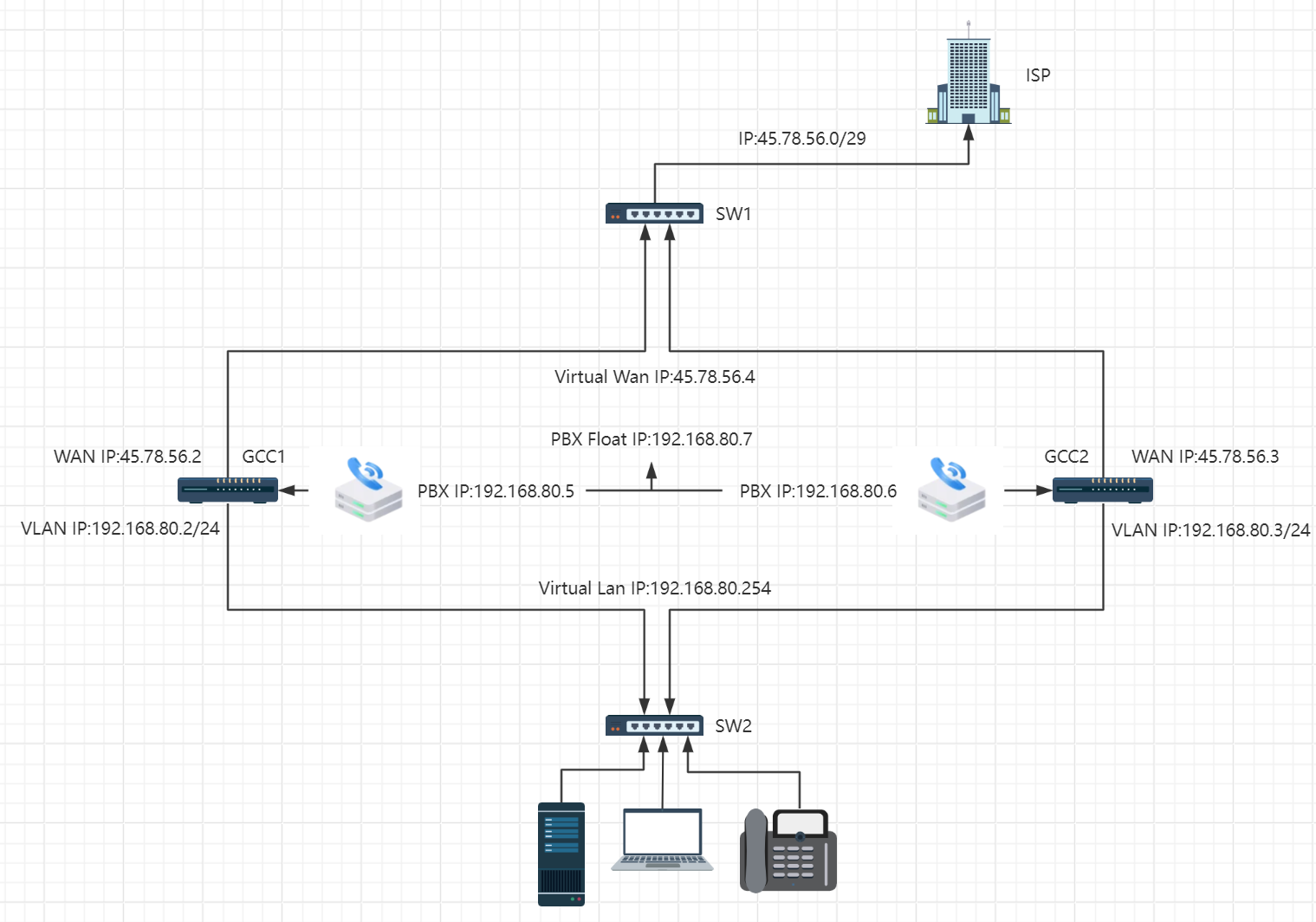
Configuration instructions:
- If two new GCCs form HA, users can select any one device as GCC1 in the example of this configuration manual.
- If one is an old GCC and the other is a new GCC to form HA, and the existing user data needs to be retained, the old GCC needs to be selected as GCC1. It is also recommended to back up the old GCC data before setting up HA.
HOT STANDBY CONFIGURATION PROCESS
Configuring VRRP
PBX HA follows the VRRP role, and the IP of PBX is in the same network segment as the default VLAN, so the VRRP of the default VLAN interface must be configured.
GCC1 VRRP environment configuration
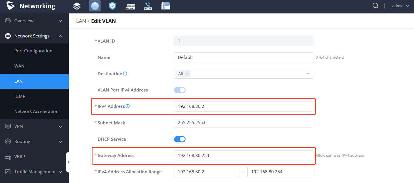
Configure the default VLAN interface
Enter the Networking module → Network Settings → LAN, and configure the Default VLAN.
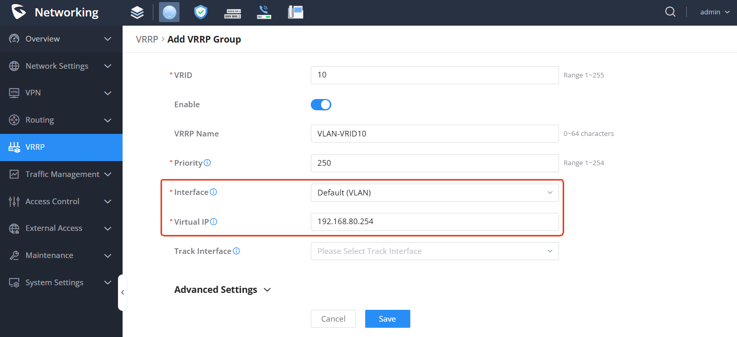
Configure VRRP for the default VLAN interface
Enter the Networking module → VRRP page and add a VRRP group.
After configuration, check the VRRP group role/status and wait for it to become Primary/Working:
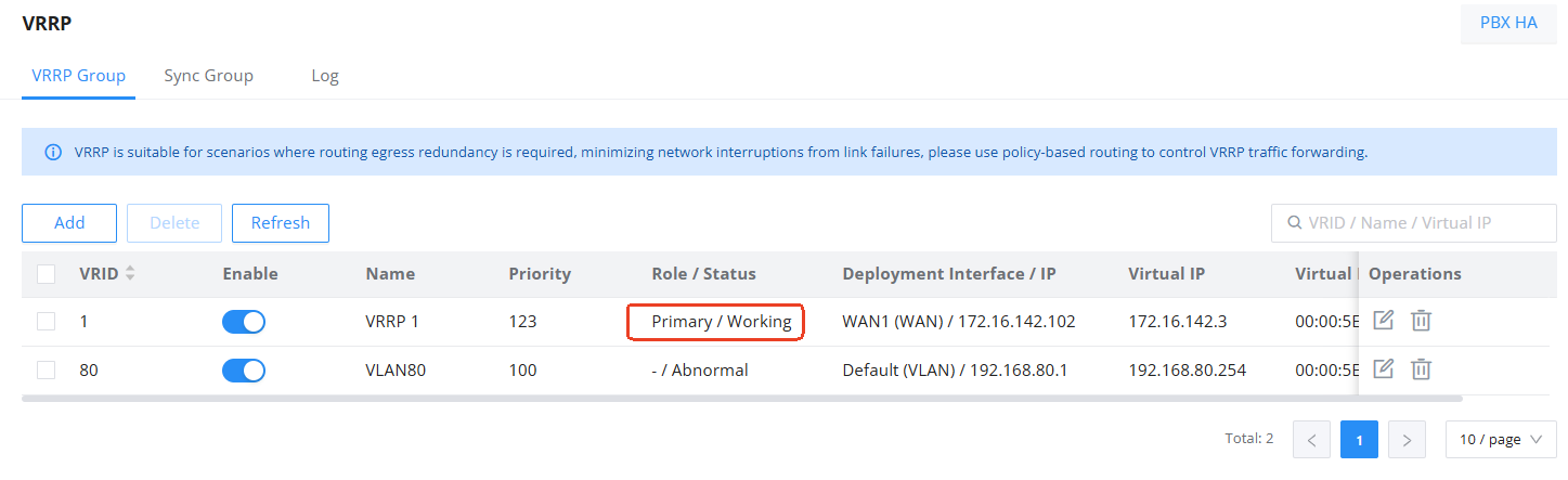
GCC2 VRRP environment configuration
Configure the default VLAN interface
Enter the Networking module → Network Settings → LAN, and configure the Default VLAN:
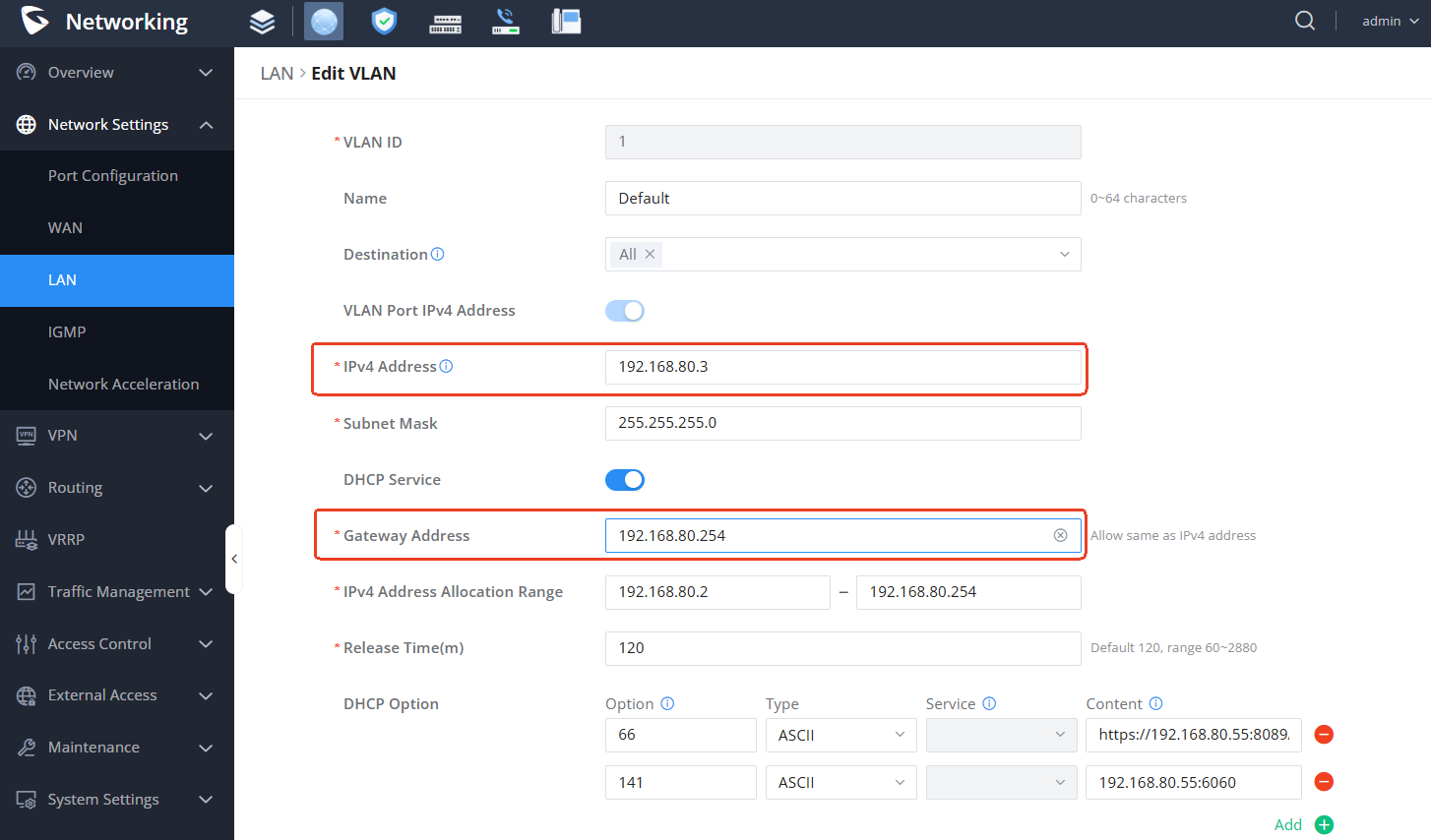
Configure VRRP for the default VLAN interface
Enter the Networking module → VRRP page, add a VRRP group, and note that the configuration priority should be lower than GCC1:
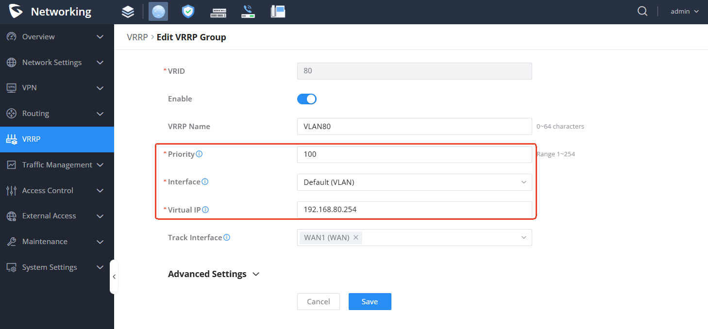
After configuration, check the VRRP group role/status and wait for it to become standby/working:

Enable HA
Before Enabling HA, you need to ensure that:
- The PBX version of GCC1 and GCC2 is the same. Users can check the version information on the Home Component Overview page.
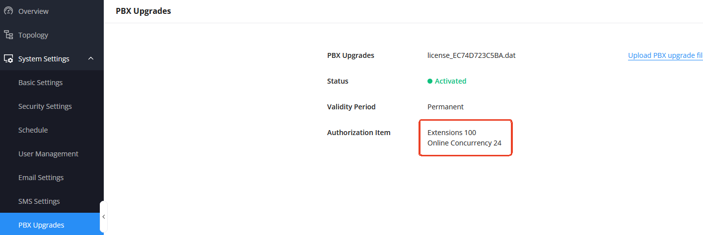
- The PBX License specifications of GCC1 and GCC2 are the same. On the Upgrades page, check the number of extensions and concurrent users.
- If you need to connect and use external storage devices, you need to ensure that the storage devices are consistent before setting up HA (including device type, device storage size, and quantity).
To view the PBX version information, go to the Home component and click the Overview page:
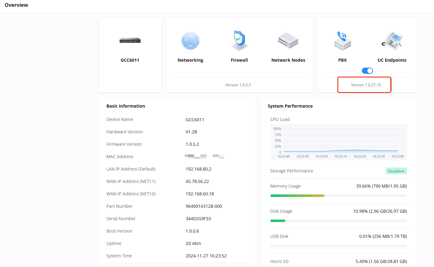
PBX License specifications, enter the Home component, System Settings → PBX Upgrades page to view:
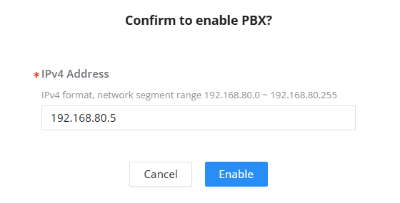
- First, configure GCC1, turn on PBX on GCC1, and configure the PBX IP address:
Enter Home and enable the PBX component:
- After the PBX is started successfully, enable HA.
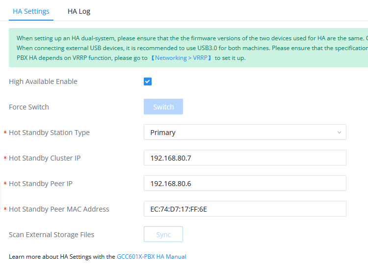
Go to Networking → VRRP, confirm that the VRRP role is active/working; then go to the PBX component, System Settings → HA page, and enable HA:
After enabling and restarting successfully, enter the PBX component and check the HA status on the System Settings → HA → HA Status page:
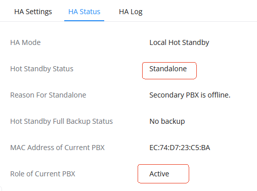
Ensure that the HA status is currently displayed as Single-node Active.
- Then configure GCC2, GCC2 starts PBX and configures the PBX IP address:
Enter Home and enable the PBX component:
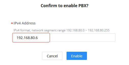
- After the PBX is started successfully, enable the HA.
After entering the Networking module and confirming that VRRP is in the backup role, enter the PBX component, System Settings → HA page, and enable HA:
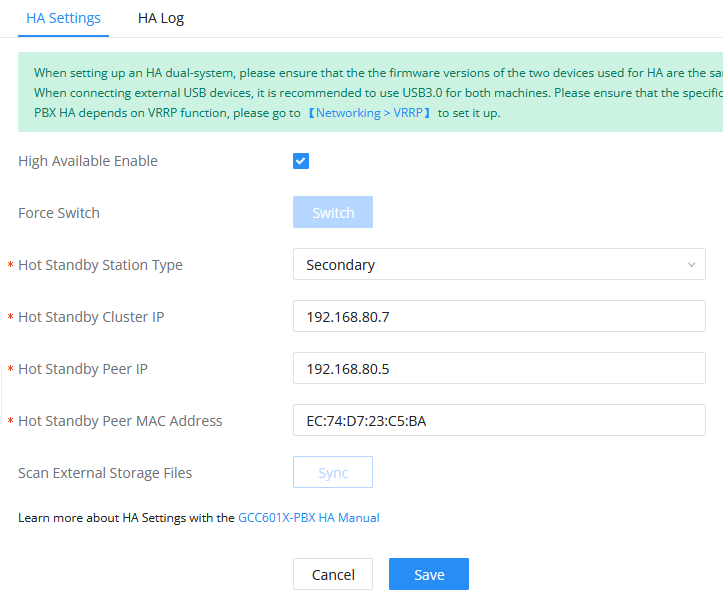
- After enabling and restarting successfully, verify the dual-machine status.
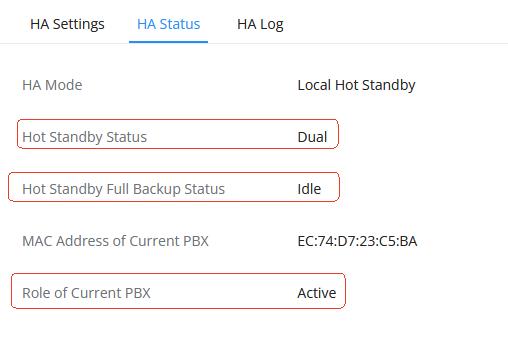
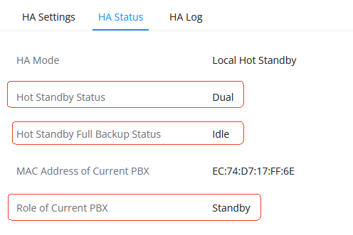
Enter the PBX component, System Settings → HA → HA Status page to check the HA status:
GCC1 is the active node of the dual-machine system:
GCC2 is a dual-machine standby:
HA configuration parameter description:
Parameter | Parameter Description | Value Range | Default Value | Remark |
HA function switch | Whether to enable the HA function | Enable/disable | Not enabled | |
HA Site Type | HA site role type | Primary/Secondary | none | One end must be configured as Primary and the other end as Secondary. The primary and standby identities are absolute and do not change with Active/Standby switching. |
Dual-machine Hot Standby Cluster IP | PBX service uses IP addresses | NA | none | HA . Only the Active device occupies this IP address. It cannot conflict with the local IP address. |
Hot Standby Peer IP | The real IP address of the peer PBX. This IP is not visible to the outside world under HA. | NA | none | IP address of the peer PBX management port |
External Storage Data Synchronization | If some file storage paths of this device are configured as SD card, USB, NAS or M.2 SSD , users can use this button to synchronize the existing files and data in the current storage path. (The storage path can be viewed in file storage management). | NA | NA | configure external storage data synchronization when forming HA for the first time. The files generated after forming HA can be automatically realized through the HA mechanism No manual configuration is required. Please ensure that both devices are connected Storage device type and quantity to prevent synchronization failure. Since backup usually takes time The time is long, it is recommended to In idle state, to avoid The system causes continuous resource consumption |
UCMRC PACKAGE RELATED CONFIGURATION
For two new GCC601X devices A and B, if the devices require UCMRC, in addition to completing the basic configuration process, the following package-related configuration is required:
- If Cloud IM service is needed, please enable Cloud IM on device A (if it is enabled before HA is established, make sure Cloud IM is disabled on device B). When using the Cloud IM server issued by GDMS, make sure that both devices use the UCMRC package with Cloud IM permission.
- Purchase the same UCMRC package with HA permissions for both devices. The order does not matter. (If A has already used the UCMRC package, you only need to purchase the package for B)
- Configure a custom server address or domain name for device A with a primary site type and use it. For specific operations, refer to the following custom server address/domain name configuration. (If device A has already been configured with a custom server address or domain name, this step can be omitted)
UCMRC Permission Package
If you want to ensure the normal use of the UCMRC package in the HA situation, you need to purchase two UCMRC packages of the same specifications with HA service rights for the GCC device through GDMS and issue them to ensure the normal operation of the HA device on GDMS. If you only purchase a single package, GDMS operation may fail due to HA backup. If you only purchase a single UCMRC package with HA service rights, HA-related functions will not work properly.
Specific steps: After logging in to the GDMS WEB page, in the GDMS Unified Communications → UCMRC → PBX Device List interface, click “Add Device” and enter the device information.

Custom Server/Domain Name Configuration
For two GCC devices that have purchased the UCMRC package with HA service, you need to configure a custom server address or domain name for the A device of the Primary site type.
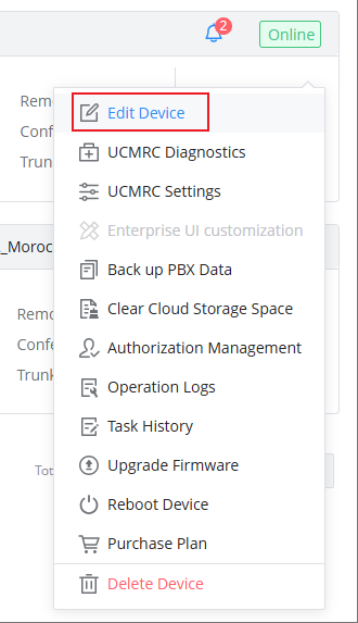
The custom server address or domain name needs to be set through GDMS, which can be configured through UCMRC → On-Premise PBX, then click on  .
.

Click on “Edit Device”
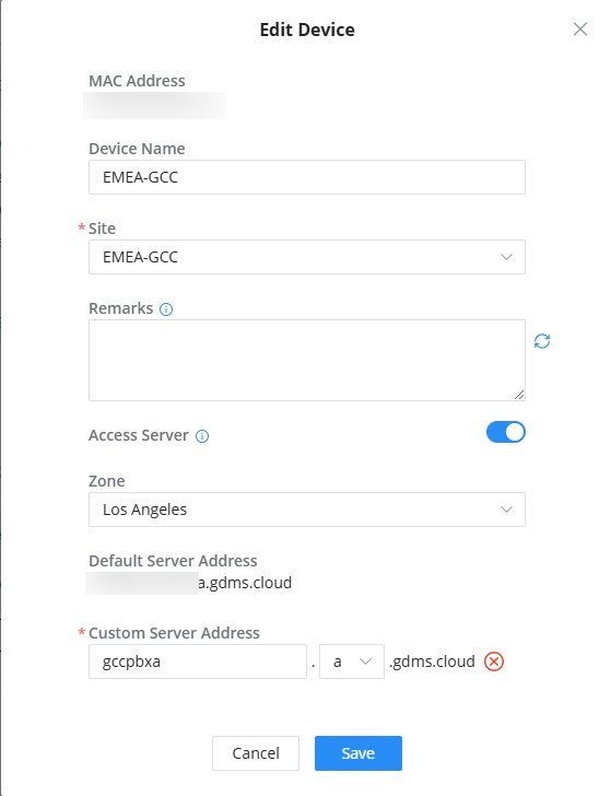
Users can configure the server address on this page. After saving, the custom domain name will be used.
After modifying the custom server address or domain name, please inform the user PBX of the new public network address.
For detailed configuration methods and questions about the custom server address or domain name, please refer to the GDMS UC User Guide.
REGISTRATION / CALL RELATED CONFIGURATION
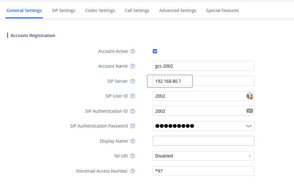
Terminals in LAN Registration via HA Cluster IP
- Taking the GXV3370 phone as an example, the phone registration configuration is:
- Wave login:
Intranet PCs can log in to Wave via https://cluster IP/gswave/#/.
For example, https://192.168.80.7:8089/gswave/#/ (where 192.168.80.7 is the cluster IP of the HA dual-machine).
Terminal Registration Through the GDMS Domain Name
After obtaining the UCMRC package, both WAN-side devices and LAN-side devices can be registered directly through the GDMS domain name.
Regardless of how the roles are switched, the domain name is based on the one issued by GDMS, and GDMS issues it based on the device initially set as Primary.
The GDMS domain name can be checked in the PBX component, System Settings → HTTP Server page:
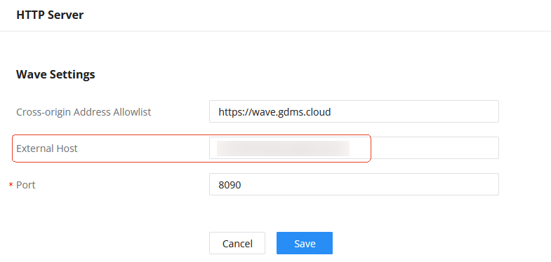
Or it can be checked on the RemoteConnect page:
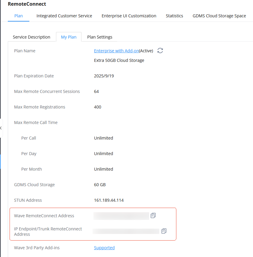
After obtaining the domain name, users can:
1. Directly access it through the browser (using Wave Web) to log in and register:
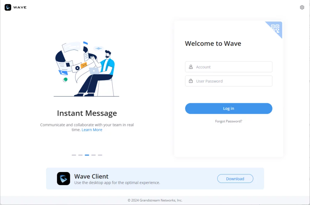
The same goes for Wave Desktop and Wave Mobile APP. Users can directly use the domain name to log in and register.
- Register the phone through the domain name:
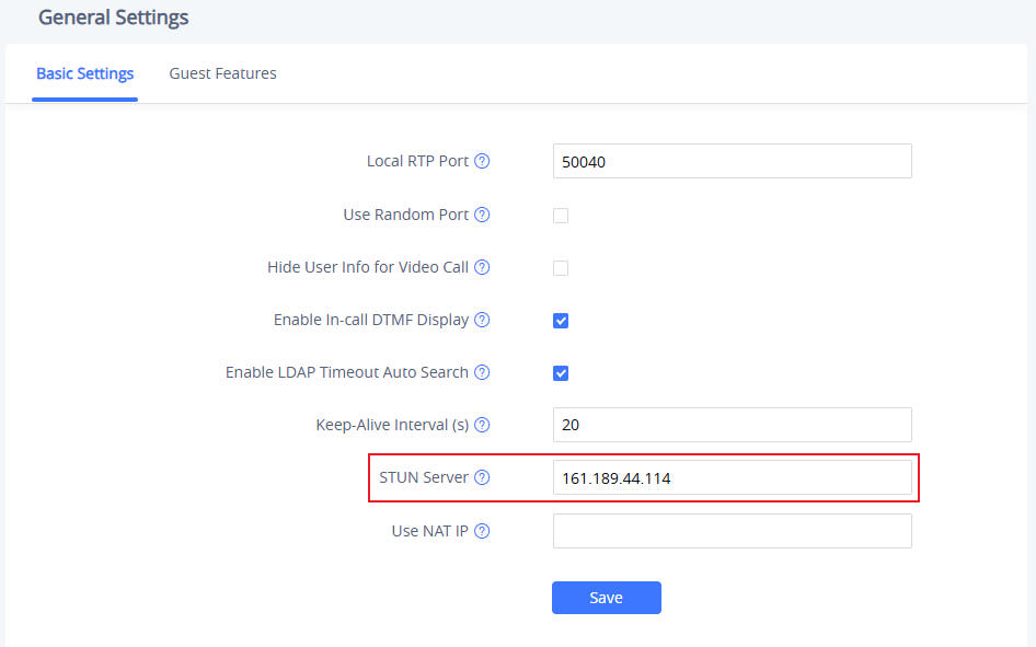
Take GXV3370 as an example. Log in to the phone web, go to Phone Settings → General Settings → Basic Settings page, and configure the STUN server (the address can be obtained on the RemoteConnect page):
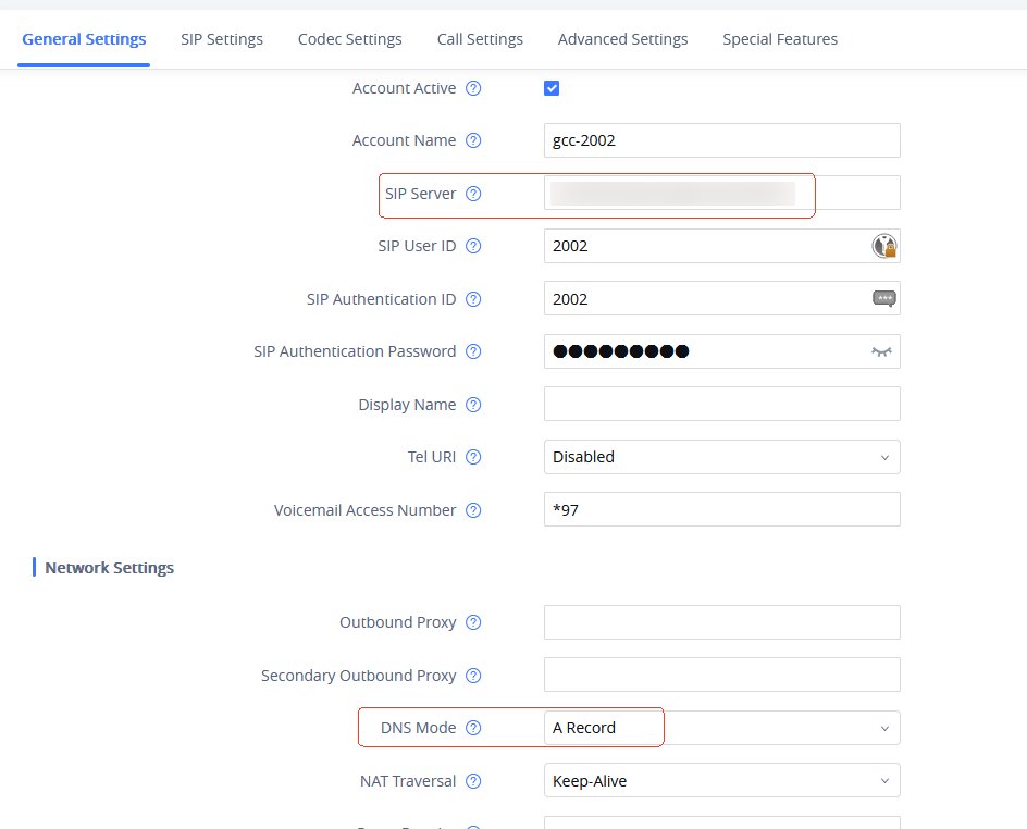
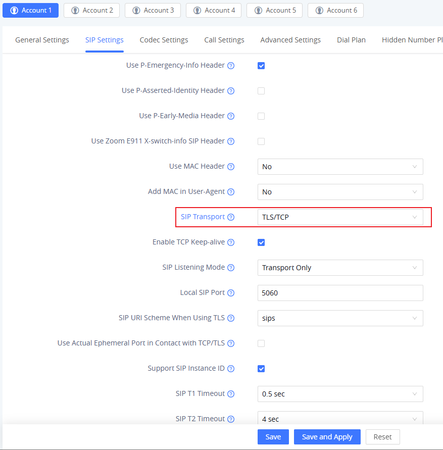
Enter the phone account page, configure the registration information, and use TLS to register. The configuration is as follows:
WAN Side Terminal Registration via WAN IP
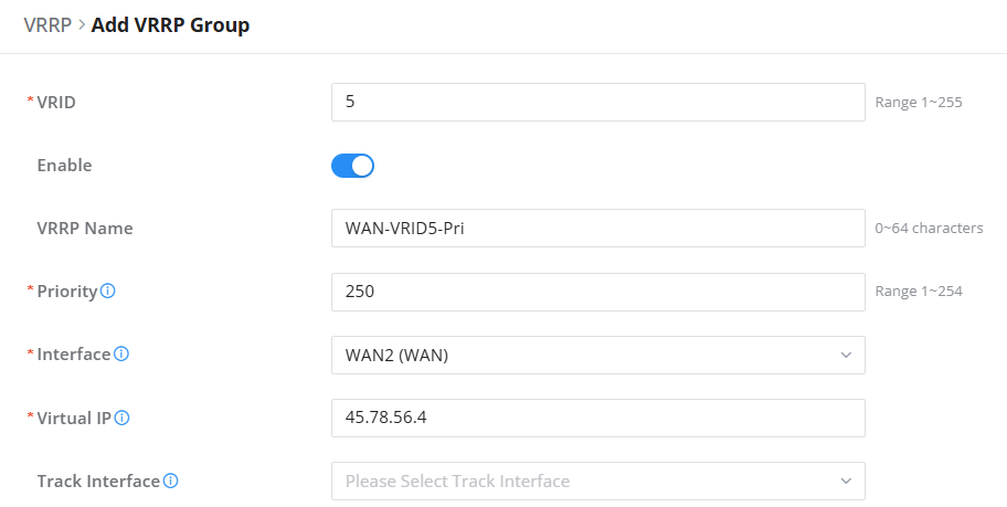
- First, configure WAN VRRP and add the WAN VRRP group to GCC1:
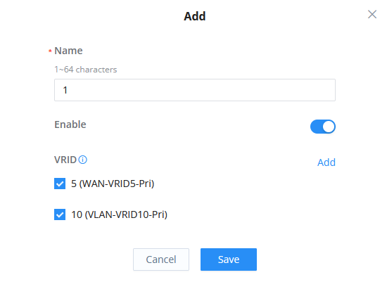
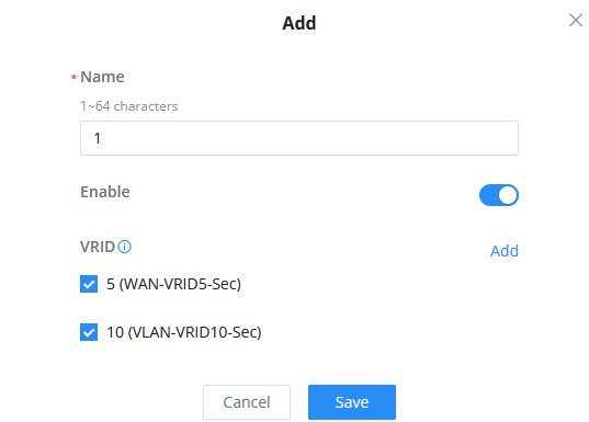
After WAN VRRP becomes the master, add WAN VRRP and LAN VRRP to the same synchronization group:
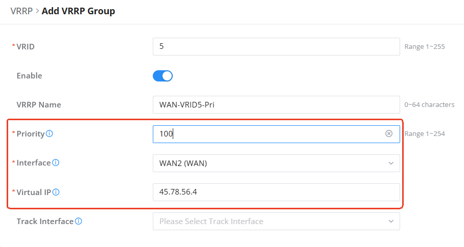
GCC2 adds WAN VRRP group:
After WAN VRRP becomes the standby role, add WAN VRRP and LAN VRRP to the same synchronization group:
2. Then configure the port forwarding rules:
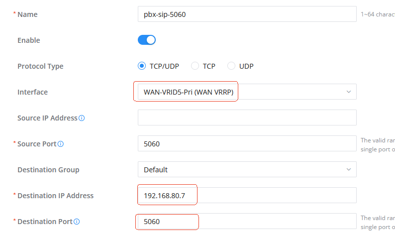
- GCC1 configures port forwarding rules:
Go to the Networking module → External Access → Port Forwarding page, and add a forwarding rule from the WAN VRRP interface source port 5060 to the PBX cluster IP address destination port 5060:
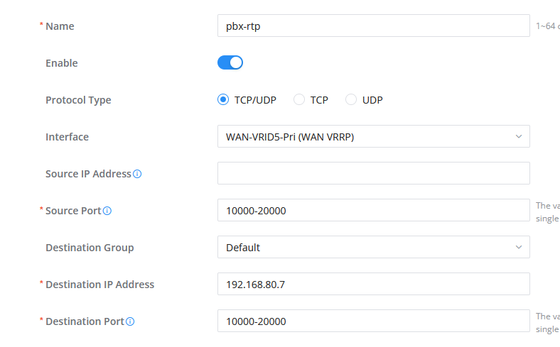
2. Add port forwarding rules for RTP:
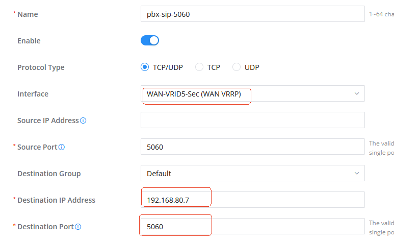
3. GCC2 configures port forwarding rules, similar to GCC1 configuration:
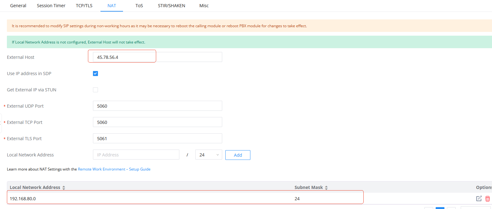
Enter the GCC1 (VRRP master, HA role Active) PBX component, PBX Settings → SIP Settings → NAT page, and configure the external address and local network address:
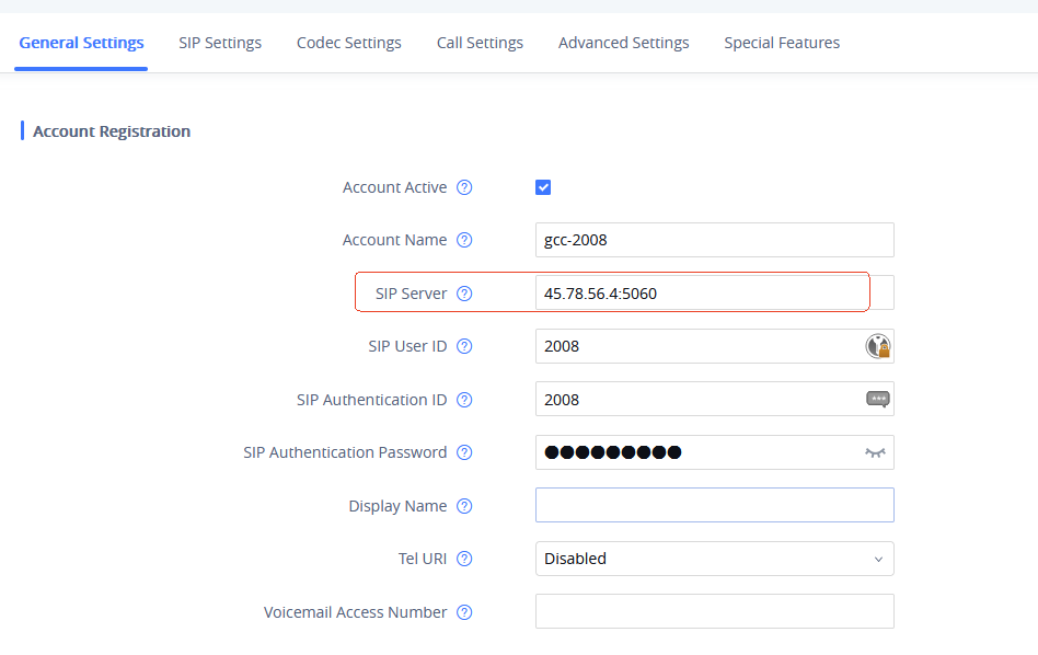
The phones on the same network segment as the WAN port can register and call through the GCC WAN VRRP virtual IP address. The following is the configuration of registration information using the GXV3370 phone as an example:
After registration is complete, users can make calls.
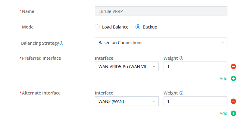
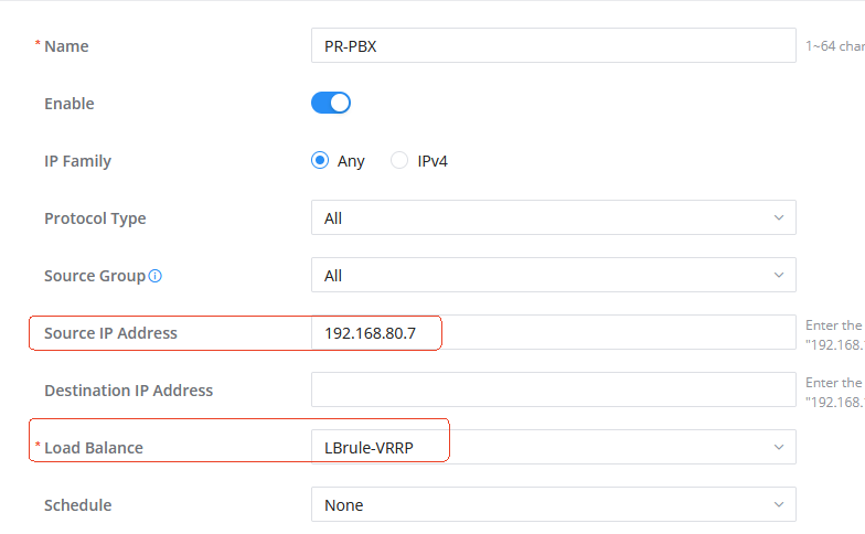
If the cross-segment terminal registers/calls through the WAN VRRP virtual IP address, policy routing configuration is also required.
GCC1 configures policy routing, and all packets sent by PBX go out from WAN VRRP:
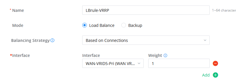
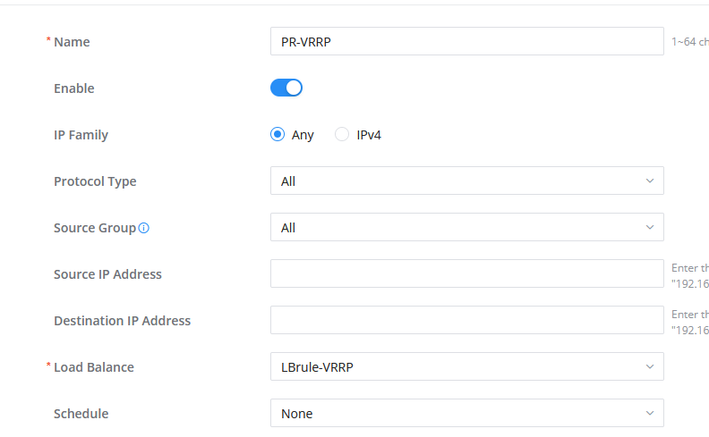
Configuration example:
HA ROLE SWITCHING
Depends on the VRRP role of the deployed interface in the same network segment as the PBX. When the VRRP role switches, the HA role switches accordingly.
HA DEVICE FAILURE, NEW DEVICE REPLACEMENT PROCESS
After a single machine has been used for a period of time, users can set up a dual machine. To avoid PBX data loss caused by the active machine being snatched away, you need to increase the priority of the currently working device before setting up the dual machine.
Here below are the steps to follow to replace a failed device in HA Dual-Node scenario, with or without UCMRC package:
HA Dual-Node without UCMRC Package Scenario
When two GCC devices that do not use UCMRC form HA dual machines, if a device fails and needs to be replaced, the example steps are as follows:
A and B have formed a HA dual-machine environment. When B fails (such as hardware failure), C needs to replace B. Before the replacement, it is ensured that the PBX version and license of C are consistent with those of A.
Device A is in Active state, and device B is in Standby state, regardless of the site types of the two:
- Disconnect the power supply of device B.
- Modify the VRRP priority of device A and set it to the highest priority.
- Modify the HA parameters of device A, change the peer MAC address from B to the MAC address of device C, save the settings, and restart.
- After A restarts, confirm that A is in an Active state and connect the physical lines to device C, including the WAN port cable and LAN port cable.
- After C is powered on, perform basic network settings. The parameters of the network settings are the same as those of B, including the WAN port IP and VLAN port IP/gateway address/DHCP service configuration; configure VRRP, and note that its priority should be lower than that of device A. After the configuration is completed, confirm that the VRRP of device A is the active role and device C is the standby role.
- Check the storage devices connected to device C to ensure that the type and number of storage devices connected to the two devices are consistent.
- Check whether Cloud IM is turned on on C’s device. If it is turned on, turn off Cloud IM on C to ensure that C replaces B without the Cloud IM service.
- Enable C and configure HA parameters. The configuration is the same as B. After the configuration is completed, save and restart. Note that C must be configured with the same site type as B.
- After C restarts, check the HA status. The display shows that both devices are in HA dual-machine status, with A as the Active role and C as the Standby role.
HA Dual-Node with UCMRC Package Scenario
When two devices purchase the UCMRC package with HA service on GDMS and form HA dual machines, if a device fails and needs to be replaced, the sample steps are as follows:
A and B have formed a HA dual-machine environment. When B fails (such as hardware failure), C needs to replace B:
Scenario 1: Site A is Primary and in Active state. Site B is Secondary and in Standby state.
- Add device C to GDMS and purchase a UCMRC package with HA permissions for device C that has the same specifications as those of devices A and B.
- Disconnect the power supply of device B.
- Modify the VRRP priority of device A and set it to the highest priority.
- Modify the HA parameters of device A, change the peer MAC address from B to the MAC address of device C, save the settings, and restart.
- After A restarts, confirm that A is in an Active state and connect physical lines to device C, including the WAN port cable and LAN port cable.
- After C is powered on, perform basic network settings. The parameters of the network settings are the same as those of B, including the WAN port IP and VLAN port IP/gateway address/DHCP service configuration; configure VRRP, and note that its priority should be lower than that of device A. After the configuration is completed, confirm that the VRRP of device A is the active role and device C is the standby role.
- Check the storage devices connected to device C to ensure that the type and number of storage devices connected to the two devices are consistent.
- Check whether Cloud IM is turned on on C’s device. If it is turned on, turn off Cloud IM on C to ensure that C replaces B without the Cloud IM service.
- Enable and configure HA parameters on C. The configuration parameters are the same as those on B. After configuration is complete, save and restart. Note that C must be configured with the same site type as B.
- After C restarts, check the HA status. The display shows that both devices are in HA dual-machine status, A is the Active role and C is the Standby role.
Scenario 2: Site A type is Secondary and in Active state. Site B type is Primary and in Standby state.
- Delete the custom server address or domain name of device B through GDMS.
- Add device C in GDMS and purchase a UCMRC package with HA permissions for device C with the same specifications as A and B. Configure C’s custom server address or domain name through GDMS. It must be the same as B’s previous custom server address or domain name and must be used by C.
- Disconnect the power supply of device B.
- Modify the VRRP priority of device A and set it to the highest priority.
- Modify the HA parameters of device A, change the peer MAC address from B to the MAC address of device C, save the settings, and restart.
- After A restarts, confirm that A is in an Active state and connect physical lines to device C, including the WAN port network cable and LAN port network cable.
- After C is powered on, perform basic network settings. The parameters of the network settings are the same as those of B, including the WAN port IP and VLAN port IP/gateway address/DHCP service configuration; configure VRRP, and note that its priority should be lower than that of device A. After the configuration is completed, confirm that the VRRP of device A is the active role and device B is the standby role.
- Check the storage devices connected to device C to ensure that the type and number of storage devices connected to the two devices are consistent.
- Check whether Cloud IM is turned on on C’s device. If it is turned on, turn off Cloud IM on C to ensure that C replaces B without the Cloud IM service.
- C Enable and configure HA parameters. The configuration is the same as B. The site type device is Primary. After the configuration is completed, save and restart.
- After C restarts, check the HA status. The display shows that both devices are in HA dual-machine status, A is the Active role and C is the Standby role.
REMOVING HA DUAL MACHINES
When the devices that make up the HA dual-machine need to release HA, directly log in to the HA Active device IP or PBX cluster IP, in System Settings → HA → HA Settings, uncheck the ” HA Function Enable” button, turn off the HA function, save the configuration, restart the device, and verify the HA status after restarting to confirm that both PBX devices have turned off HA.
DUAL-MACHINE CLOUD IM SCENARIO
Please ensure that only one Cloud IM service is enabled on the two GCCs (PBXs) that form the HA dual-machine. When using the server address or domain name issued by GDMS, please ensure that both use the package with Cloud IM permissions.
When Cloud IM is enabled on the Active device A that forms the HA dual machine, the Standby device B will obtain the Cloud IM service along with the HA data backup. Cloud IM will provide services along with the Active device, and the MAC address of the bound device will change with the role switch, so when the active-standby switchover occurs, Cloud IM will not be affected.
When device B fails, when device C without Cloud IM enabled replaces device B to form a dual-machine system with A, Cloud IM will still provide HA services for B and C, and no other configuration is required. If device C has Cloud IM enabled, you need to disable the original Cloud IM first to ensure that C replaces B without Cloud IM service. For more details about device replacement, refer to [HA DEVICE FAILURE, NEW DEVICE REPLACEMENT PROCESS].
DUAL-MACHINE UCMRC REMOTE ACCESS SCENARIO
Purchase a UCMRC package with HA permissions. After the HA package binding is successful, the GDMS page will display Primary (Host) type devices and Secondary (Spare) type devices:


UCMRC Role Switching Process
Prerequisites:
- HA permissions on GDMS.
- The primary and backup packages are successfully sent and bound.
Business implementation:
- The call service is completed by the interaction between GDMS and Active working state devices.
- When the Active working state device A fails and causes a master-slave switchover, the Standby working state device B takes over the service and enters the Active working state. Device B sends a master-slave switch command to GDMS, informing it that subsequent service interactions will be completed by device B and GDMS.
UCMRC Role Status
It should be noted that when the two machines purchase the UCMRC package with HA permissions, the role status will be actively reported to GDMS by GCC (PBX), and there is no need to manually specify it on GDMS.
At the same time, for GDMS, different remote operations can still be performed on the two PBXs, but some operations on the standby machine will fail and be reset due to HA backup. The service is provided by the Active role PBX, but GDMS always sends the Wave login domain name according to the Primary device.
SERVICE STATUS
Active/Standby Working Status
The GCC (PBX) device completes the HA configuration, the IP for providing services to the outside world is the cluster IP. Full backup data synchronization will be performed during the initial system startup phase, that is, the Standby role PBX requests full data from the current Active role PBX. The Standby role PBX is ready to take over the Active role PBX business at any time, and changes to the Standby role PBX business data will also be restricted. Daily data on the Active role PBX will be synchronized to the Standby role PBX in real-time. When the Active role device fails, including hardware failure and network failure, the standby VRRP is promoted to the master, and the PBX Standby role is upgraded to the Active role. The new Active device immediately takes over the business to ensure that the business is not interrupted, and the original Active role PBX will restart and become the Standby role. At the same time, some calls will be automatically restored.
PBX Administrator Login Method
- Access the PBX component by logging into the GCC page.
It is relatively simple to access the PBX component by logging in to GCC. This is the recommended way to access the PBX.
- Log in using the PBX independent page
The cluster IP becomes a floating IP for providing external services. To perform regular service configuration on the PBX page, you only need to log in and access it according to the cluster IP address format. Regardless of how the roles are switched, the floating IP remains unchanged and is always bound to the PBX with the Active role that currently provides services.
Intranet PCs can log in to the current Active PBX via https://cluster IP:8089 or https://current Active PBX IP:8089. In particular, after logging in to the Standby PBX via https://current Standby PBX IP:8089, the business data configuration will also be restricted.
It should be noted that after forming HA, the administrator identity of the Active device will also be synchronized to the Standby device and overwrite the administrator information of the Standby device. Therefore, whether logging in through the floating IP or logging in to the IP addresses of the two PBX devices, use the administrator identity and account of the Active role to log in.
Since the top-level configuration of GCC is not synchronized between the master and the slave, it is recommended that the same user and password be configured on the master and slave GCCs before setting up HA.
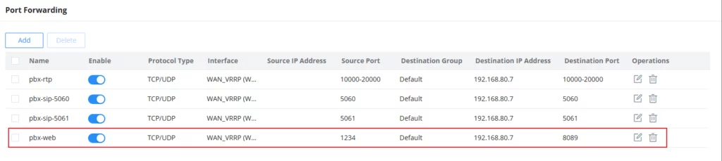
The external PC can log in by configuring port forwarding rules:
For example, configure port forwarding rules for the WAN VRRP interface on both the active and standby devices to enable the WAN-side PC to log in to the Active PBX by accessing the WAN VRRP IP+port regardless of how the VRRP & HA roles are switched:
CALL HOT STANDBY
When a device in the Active role fails (the VRRP role switches and the HA role switches accordingly), if there is an ongoing call in the system, the call voice will only be briefly paused during the Standby and Active role switching process, and the call can be restored within a few seconds.
DATA SYNCHRONIZATION
The HA dual-node scenario provides a complete data synchronization mechanism, including the following points:
- Full backup data synchronization at the initial startup of the system, that is, the full data requested by the Standby PBX to the current Active PBX. The Active PBX will also synchronize the configuration actions to the Standby PBX in real-time during each service configuration to achieve consistency between the two sides. The data that is triggered to be synchronized to the Standby PBX in real time is not limited to configuration data but also includes adding extensions, voice messages, CDRs, local recording files, etc.
- Perform full backup synchronization at 3:00 a.m. to ensure that the data between the two machines is always consistent. During full backup, the HA full backup status will display “backup in progress” in real-time, and “idle” will be displayed at other times.
BACKUP PACKAGE EXPORT AND RESTORATION
The backup package of PBX components can be backed up to GDMS or restored from GDMS cloud storage on the PBX component Maintenance → Backup page. Backup and restoration can also be performed on the top-level Maintenance → Backup&Restore page.
The running HA dual machine:
- If you want to restore the backup package of a device with HA enabled, you only need to restore the backup package on the Active device. After the restoration, both PBXs will automatically restart. After the Active restart is complete, the configuration and data will be fully backed up and synchronized to the Standby device.
- If you restore the backup package of a device that does not have HA enabled, you need to first disable HA on the Active and then perform the restore. After the restore is complete, re-establish the HA dual machine.
MAINTENANCE INTERFACE
HA dual-machine applications, we can check whether there are any HA-related alarm events from System Management → System Events, to directly know whether there are any system abnormalities:
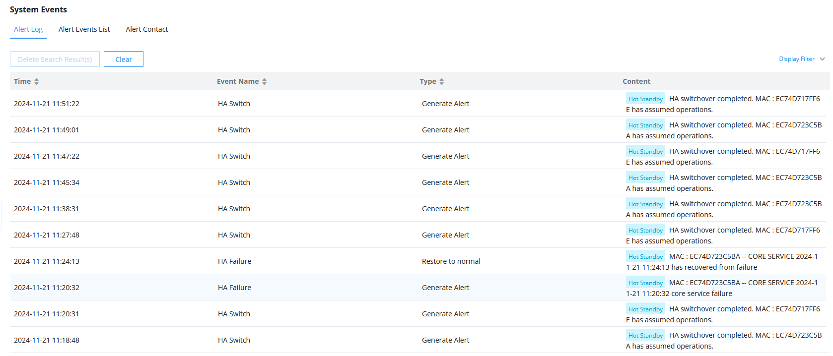
View the relevant backup logs and switchover logs through System Settings → HA → HA Log. The HA log effectively records the execution results of the past full backup actions and the historical records of triggering the active/standby switchover:


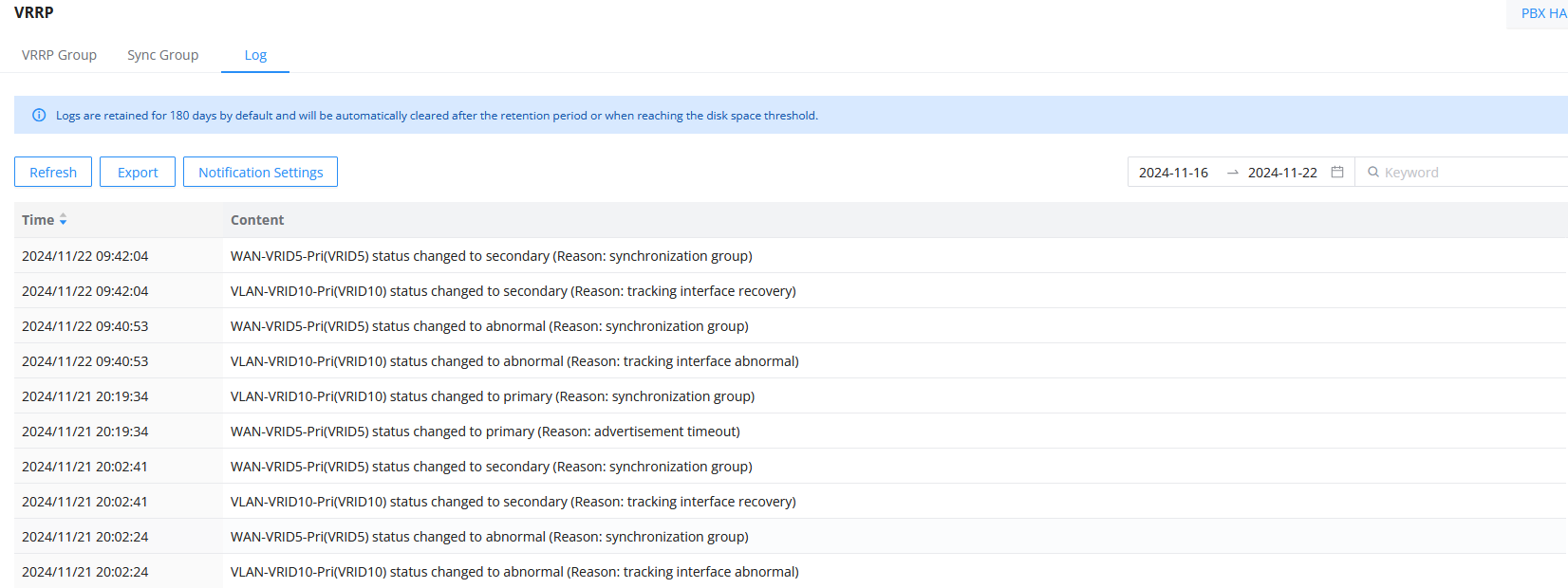
Since the PBX HA master/slave roles are consistent with the VRRP master/slave roles, when the VRRP master/slave switches, the HA switches accordingly. In the HA switchover log, only the switchover record can be seen, but the specific switchover reason needs to be checked on the network component, VRRP → Log page: