
One-way interlocking doors mode on GDS3710 allow to control two doors for access control in one-way mode. Once the card or PIN is fully validated by the GDS3710, it will check the status of both doors (using 3rd party window/door sensors – not provided by Grandstream – to verify if they are opened or closed), if both doors are closed the Door 1 will open allowing the person to pass through hallway, once the Door 1 is closed it will start counting and when the timeout is reached, the Door 2 will open granting access to the person in the facility.

This feature can be used in application scene like: College Dorm, Bank Branches, Government Offices, Medical Clinics, Private Clubs, etc., where there are two doors in place, high security and flow control is required (only one entry per time) but security guard may not be on site always.
FUNCTIONALITY
One-way interlocking doors mode will allow GDS3710 to control two doors in one direction, with additional 3rd party window/door sensor installed accordingly (not provided by Grandstream).
When configured and wired correctly, the two doors will operate under a controlling logic as below:
- Only legal PIN or RFID card can open door when BOTH doors are detected closed.
- When 1st door opened by valid user, the 2nd door is and will remain closed; the 2nd door will automatically open once detected the 1st door closed and programmed timer reached.
- When 2nd door opening, the 1st door will NOT open even if a valid PIN/RFID is used.
- If entering 1st door and after 1st door closed and 2nd door opened, the person failed to enter 2nd door promptly (after 2nd door opening time out) will be locked in between two doors until next transaction happens or ask help (e.g.: call posted number or press button if there is one) from security staff to open door remotely (via SIP call into GDS3710 or GDSManager, for example) .
This open-door logic will make sure two doors are open in “One-Way” direction, at any given time only one door can be opened, and only one legal open-door request is allowed to execute. The hallway or scene between two doors could be monitored by installing Grandstream IP cameras.
WIRING DIAGRAM
The example below shows how to use wiring on the back cover of the GDS3710 to connect with 2 external Lock strike “Fail Secure Model” and 2 Door Sensors:
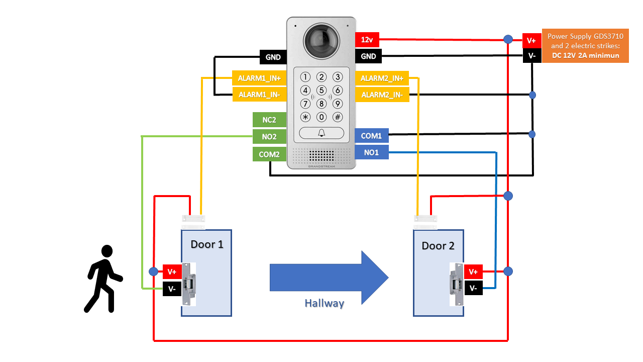
Under this diagram the GDS3710 will be placed in Door 1 in order to control the two doors allowing one-way (entrance from Door 1 to Door 2) to the facility
GDS3710 WEB CONFIGURATION
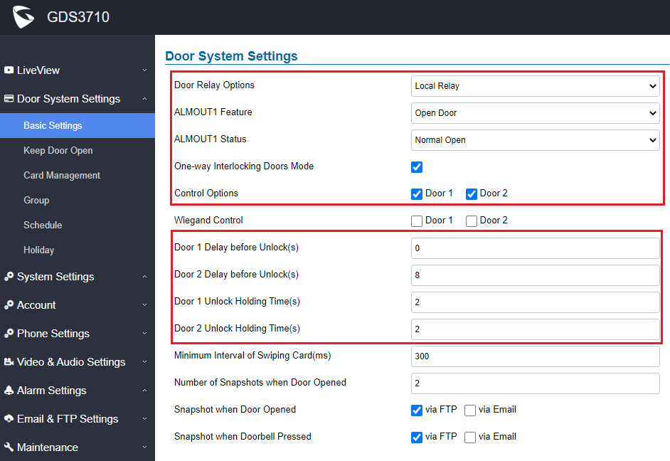
For example, the GDS3710 can be installed to control 2 doors using one-way interlocking door mode when enable this feature please do the following:
- ALMOUT1 Feature: Open Door
- ALMOUT1 Status: Normal Open
- Control Options: Door1 & Door 2 Checked
Digital Input to Check Door Status (Door 1 & Door 2)
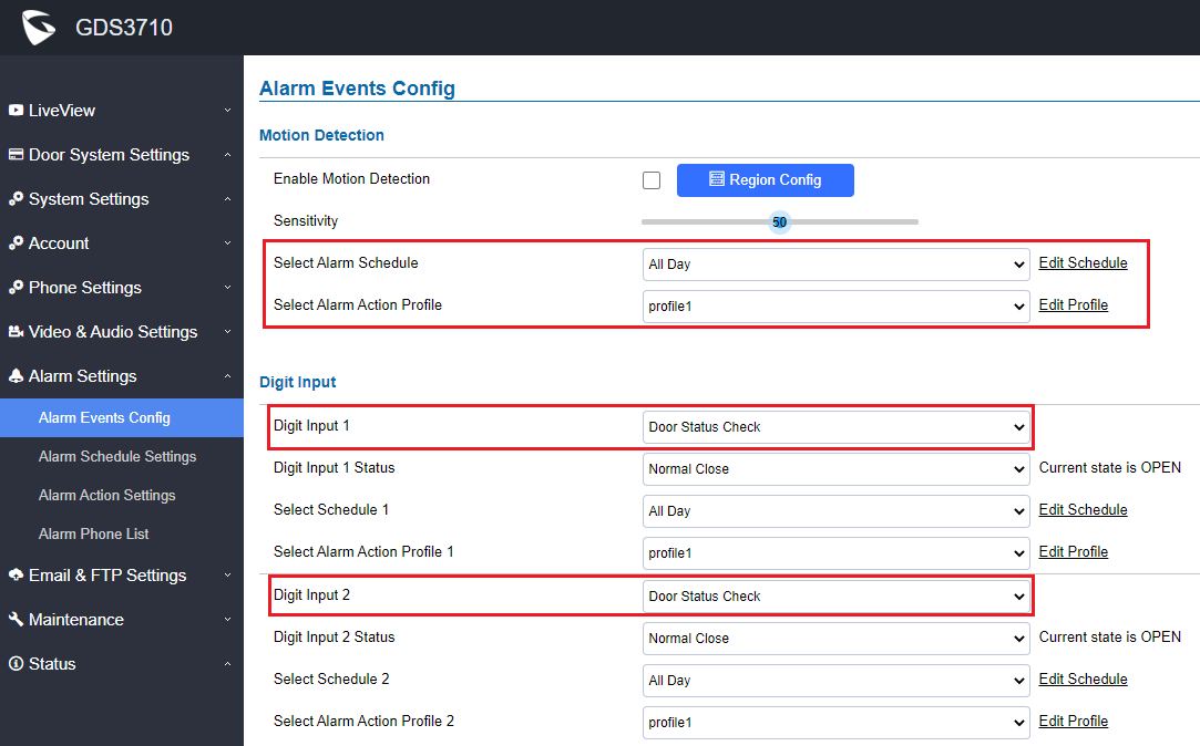
Go to Alarm Settings 🡪 Alarm Events Config 🡪 Digit Input 1 & 2, configured as follow:
Digit Input 1: Door Status Check. The DI will validate the current status of the Door, whether it is close or open, based on the sensor signal sending to the “Digit input 1”
Digit Input 1 Status: If set to Normal Open: Configured door status check will be triggered when Digital Input Status switch from Close to Open, If set to Normal Close: Configured door status check will be triggered when Digital Input Status switch from Open to Close. By default, Input Digit 1 Status is “Disabled”.
Digit Input 2: Door Status Check. The DI will validate the current status of the Door, whether it is close or open, based on the sensor signal sending to the “Digit input 2”
Digit Input 2 Status: If set to Normal Open: Configured door status check will be triggered when Digital Input Status switch from Close to Open, if set to Normal Close: Configured door status check will be triggered when Digital Input Status switch from Open to Close. By default, Input Digit 2 Status is “Disabled”.
Private PIN or Card & Private PIN
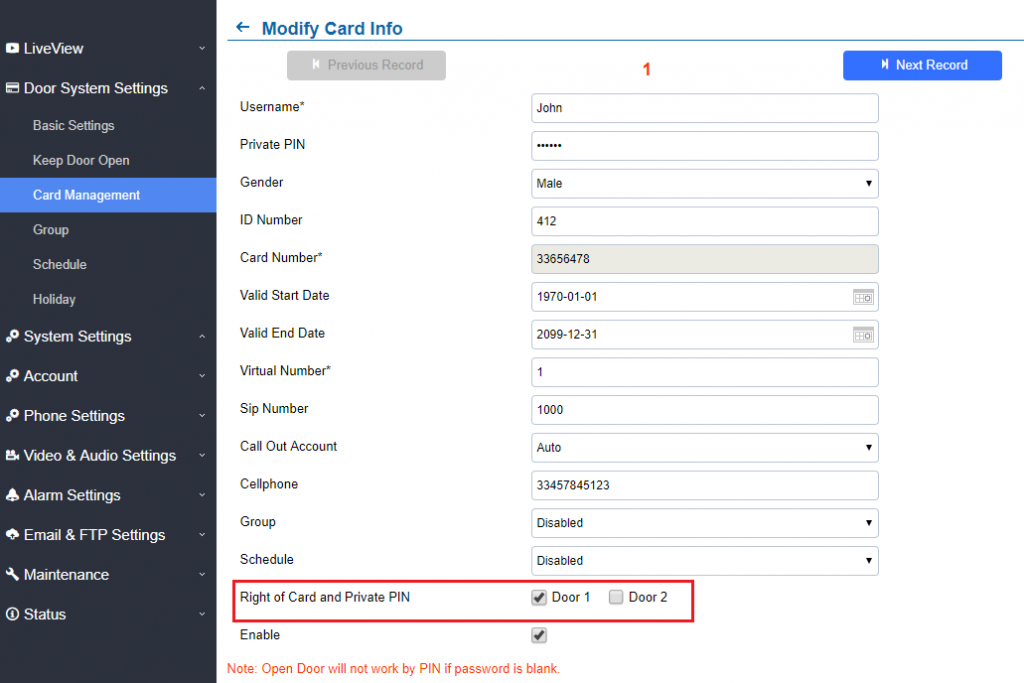
If using RFID card or Private PIN to open door, then which door can be opened by the RFID card or Private PIN is configured via “Card Management”, see above screenshot.
SUPPPORTED DEVICES
Following table shows the supported products and the minimum firmware to use:
Product | Firmware |
GDS3710 | 1.0.7.23 |