
GDS3710 HD IP Video Door System is a hemispheric IP video door phone and a high-definition IP surveillance. GDS3710 is ideal for monitoring from wall to wall without blind spots. Powered by an advanced Image Sensor Processor (ISP) and state of the art image algorithms, it delivers exceptional performance in all lighting conditions. The GDS3710 IP video door system features industry-leading SIP/VoIP for 2-way audio and video streaming to smart phones and SIP phones. It contains integrated PoE, LEDs, HD loudspeaker, RFID card reader, motion detector, lighting control switch, Alarm input/output and more.
This How-To Guide will describe the wiring and steps to follow to control two door from the GDS3710.
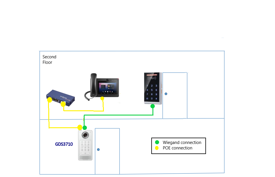
GDS3710 WIRING CONNECTION FOR TWO DOORS
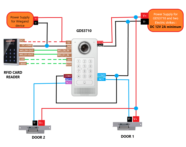
Wiring example
Below example, show how to use wiring on the back cover of the GDS3710 to connect with 2 external lock strike
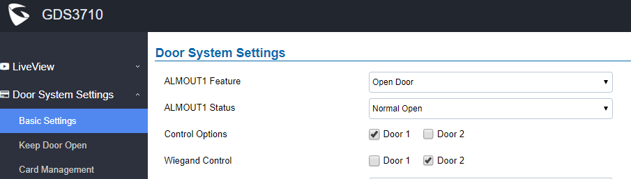
GDS3710 Web Configuration to control two doors
Configuration example
For example, a 3rd party Wiegand Input device or GDS3710 can be installed to control Door2. We have selected Door 1 on “Control Option” to be controlled by local PIN and the build in RFID reader, and we enabled wiegand control for Door 2 only.
Notes:
In case of a power loss then the DOOR STATUS when power is off will be depending on the following situations:
- COM2 has three wiring PINs, corresponding to NO or NC accordingly. Therefor when connecting NC2 and COM2 (Fail Safe) then strike will open when power is lost and when using a NO2 strike (connecting COM2 and NO2) then door is “locked” when power is lost (Fail Secure).
- COM1 (ALMOUT1) has only two PIN, and NO ONLY. If the connected strike/lock is a NO strike, this means ALMOUT1 Status should be set to “Normal Open” then door will be closed when power is lost, while if the strike connected is NC strike, and ALMOUT1 Status is set to “Normal Close” then door will be open when power is lost.
Universal PIN for Operation of Doors
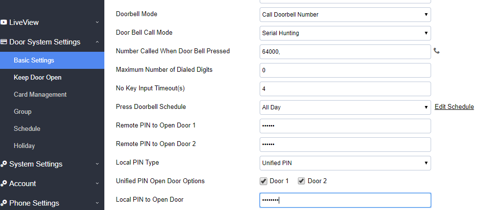
If Unified PIN (Universal PIN) is configured to open door, then which door can be controlled by the PIN is configured in the UI once “Unified PIN” selected.
For example, like above screenshot, if this universal PIN is set to open both Door1 and Door2, but due to previous “Control Option” set to open Door1, and “Wiegand Control” set to open Door2, therefore the final result will be the INTERSECT result of both sets with condition qualified.
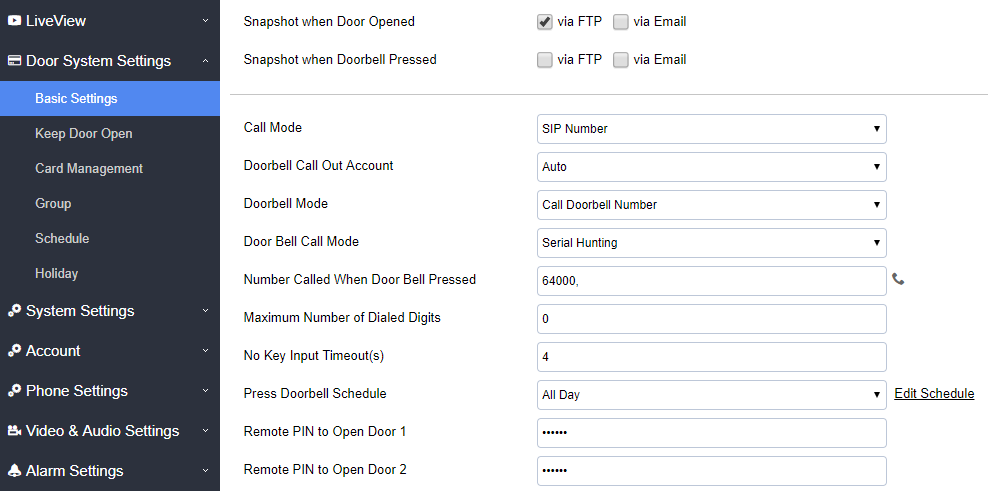
Remote PIN to Operation of Doors
For remote PIN to open door, the PIN can be configured in example down below.
The PIN can be different for Door1 and Door2 and has to be configured correctly in related IP Phone which will be used to operate “One Key Open Door”.
If BOTH doors need to be opened at the same time, then both Door1 and Doo2 has to be configured with exactly SAME password or PIN as DTMF open door.
On the Basic settings page set the following fields:
Private PIN or Card & Private PIN
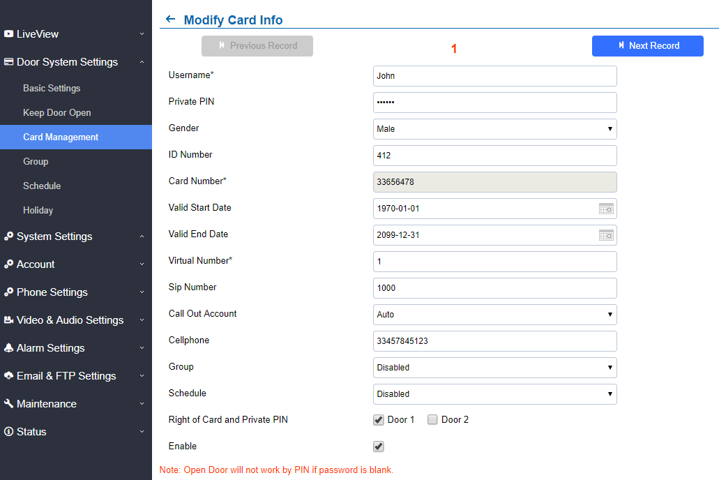
If using RFID card or Private PIN to open door, then which door can be opened by the RFID card or Private PIN is configured via “Card Management”, see above screenshot.