OVERVIEW
The GSC3506 V2 is a 1-way public address SIP speaker that allows offices, schools, hospitals, apartments and more to build powerful publicaddress announcement solutions that expand security and communication. This robust SIP speaker offers crystal clear HD audio functionality with a high-fidelity 30-Watt HD speaker. The GSC3506 V2 support builtin whitelists ,blacklists and greylists to easily block unwanted calls, SIP and multicast paging, group paging and PTT. users can easily sculpt a state-of-the-art security and PA announcement solution. Thanks to its modern industrial design and rich features, the GSC3506 V2 is the ideal SIP speaker for any setting
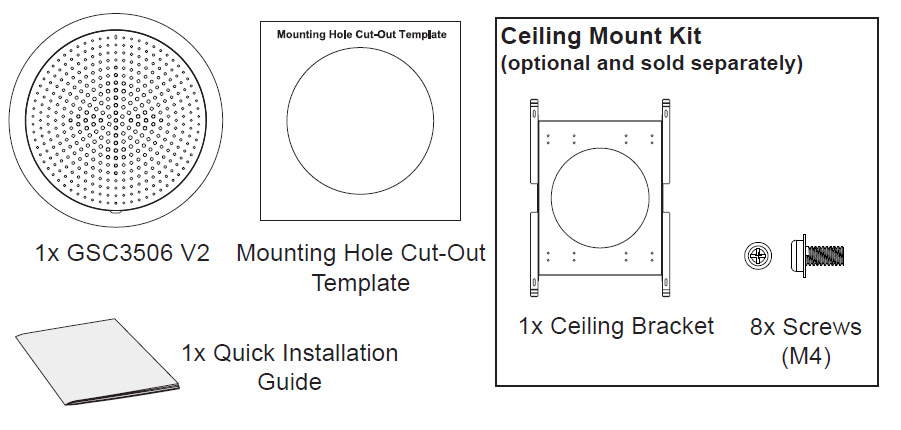
PACKAGE CONTENTS
GSC3506 PORTS AND BUTTONS
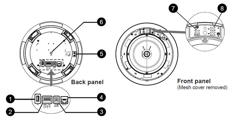
NO. | Port | Label | Description |
1 |  | USB Port | USB2.0, External USB Storage |
2 |  | Auxiliary | 2-pin Switch-in input port /2-pin Alarm-in input port /2-pin differential line out port /1-pin GND port |
3 |  | DC24V port | One DC24V port |
4 |  | NET/PoE | Ethernet RJ45 port (10/100Mbps) supporting PoE/PoE+/PoE++. |
5 |  | Security | Security Eyebolt (Must Attach) |
6 |  | Ceiling | Ceiling hole position |
7 |  | Reset | Factory reset button. Press for 10 seconds to reset factory default settings |
8 |  | Volume | Sound Volume buttons |
HARDWARE INSTALLATION
GSC3506 V2 can be mounted on the ceiling, boom or using ceiling bracket. Please refer to the following steps for the appropriate installation.
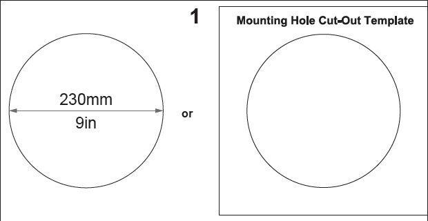
Ceiling Mount
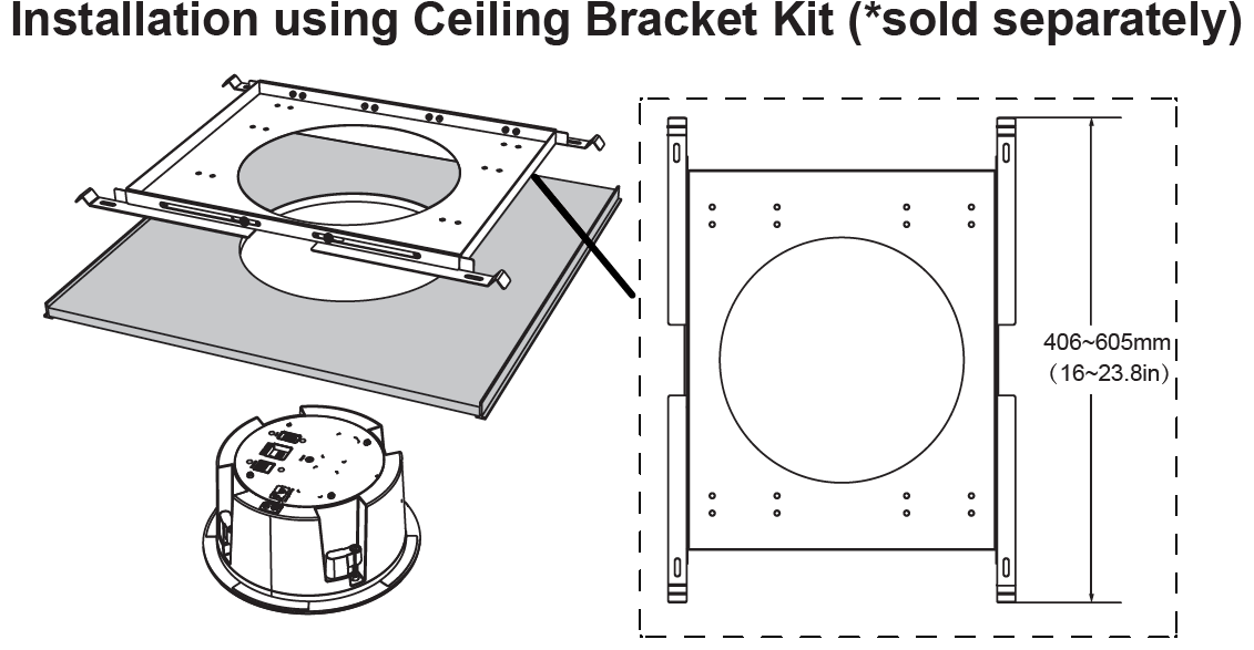
- Drill a round hole with a diameter of 230mm or use the Mounting Hole Cut-Out Template.
Then Fix the Ceiling Bracket using the screws from the kit as shown in the illustration (optional)
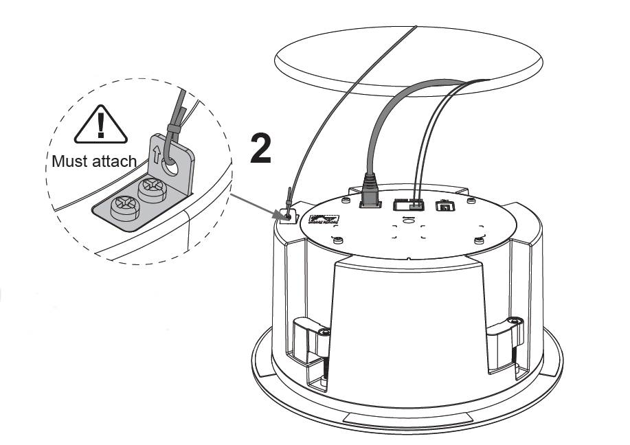
2. To ensure safety, install first the anti-fall ropes, then plug in the Ethernet and 2-pin cables.
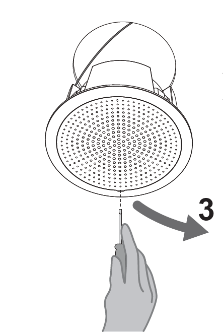
3. Open the front cover with a flat-head screwdriver.
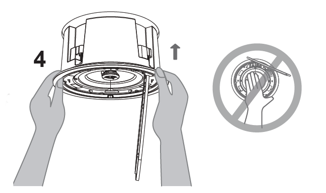
4. Align the device with the hole and push it up slowly with two hands.
5. Use a screwdriver and gently rotate clockwise the screws marked as (1), (2), (3), and (4) in the step 5 illustration.
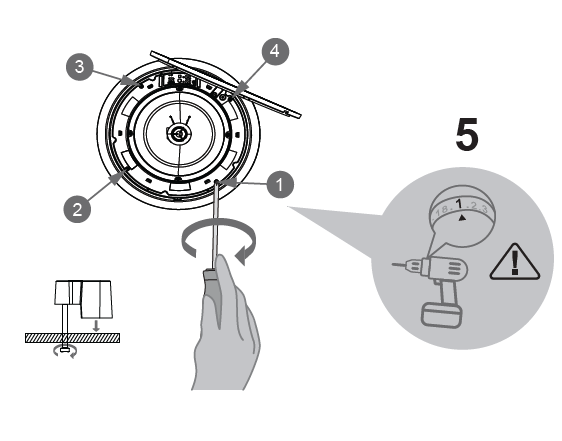
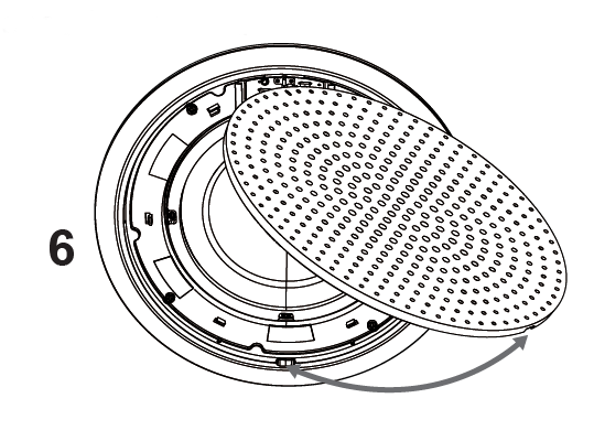
6. Align the notch on the front cover with the notch on the device, and press the whole front cover to ensure that each buckle is fastened.
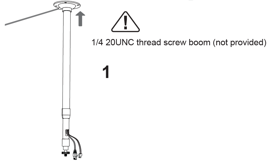
Boom Mount
- Fix the Boom in the ceiling.
2. To ensure safety, install first the anti-fall ropes.
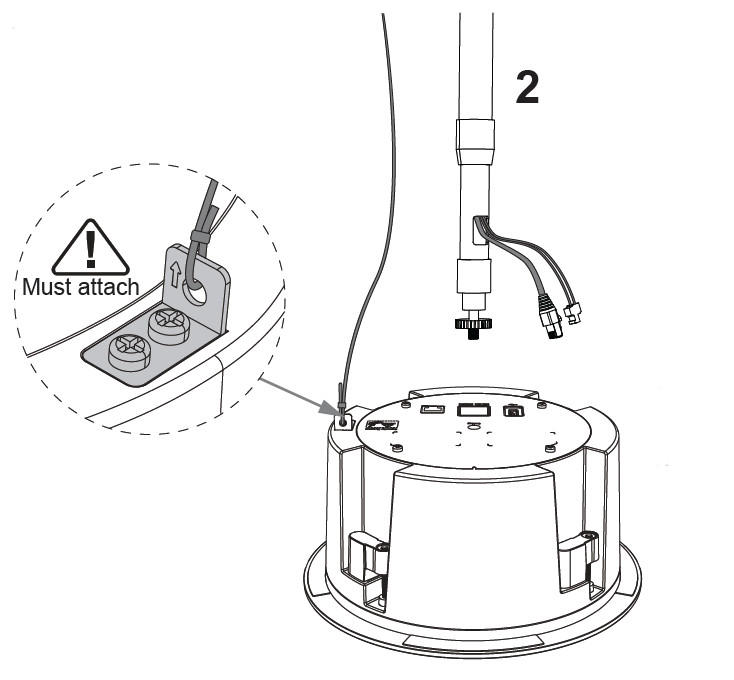
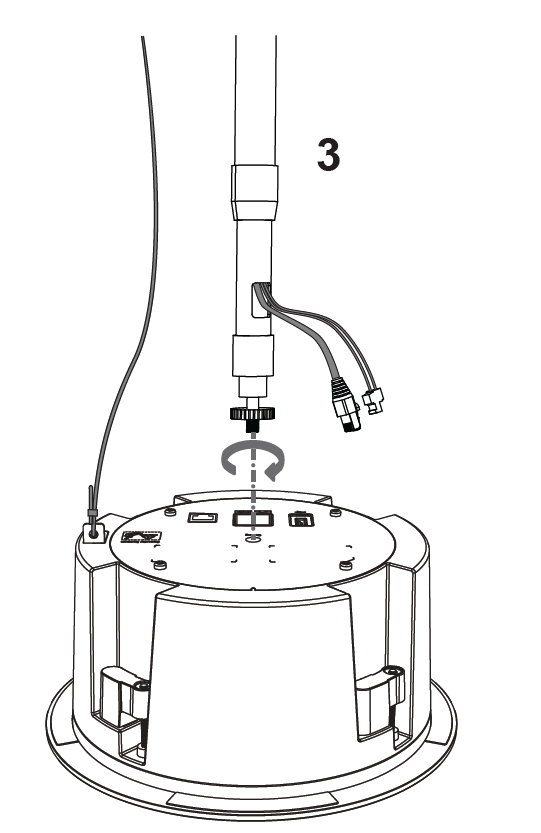
3. Attach the Boom with the GSC3506 V2 ceiling hole and rotate to fix it in place.
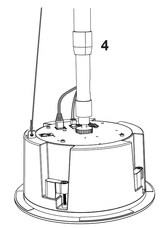
4. Plug in the Ethernet and 2-Pin 24V Power supply cable.
POWERING AND CONNECTING GSC3506 V2
GSC3506 V2 can be powered on using PoE/PoE+/PoE++ switch or connecting the 2-Pin 24V Power supply cable.
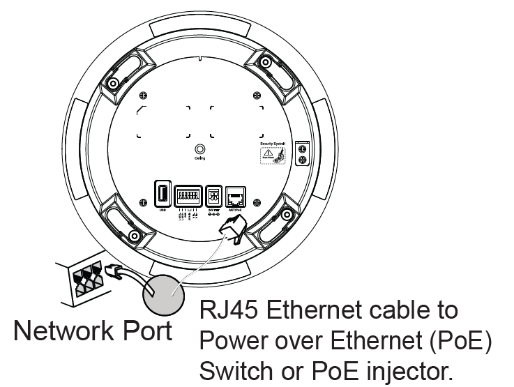
Using PoE Switch
Step 1: Plug a RJ45 Ethernet cable into the network port of the GSC3506 V2.
Step 2: Plug the other end into the power over Ethernet (PoE++) switch or PoE injector.
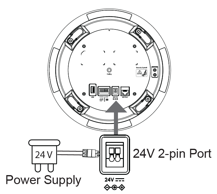
Using 2-Pin 24V Power Supply cable
Step 1: Connect a 24V Power Supply.
Step 2: Connect the 24V Power Supply cable with the 24V 2-pin Port (as shown in the illustration)
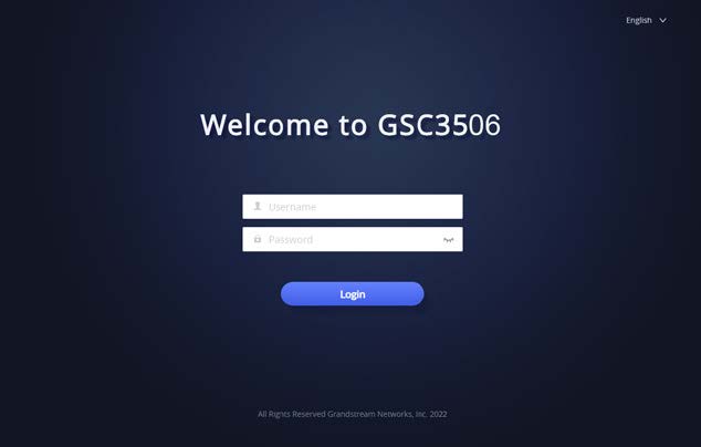
ACCESSING THE CONFIGURATION INTERFACE
A computer connected to the same network as the GSC3506 V2 can discover and access its configuration interface using its MAC address :
- Locate the MAC address on the MAC tag of the unit, which is on the underside of the device, or on the package.
- From a computer connected to same network as the GSC3506 V2, type in the following address using the GSC3506 V2’s MAC address on your browser: http://gsc_.local
Example: if a GSC3506 V2 has the MAC address C0:74:AD:11:22:33, this unit can be accessed by typing http://gsc_c074ad112233.local on the browser.
For more information, please refer to GSC3506 V2
User Manual at: https://www.grandstream.com/support