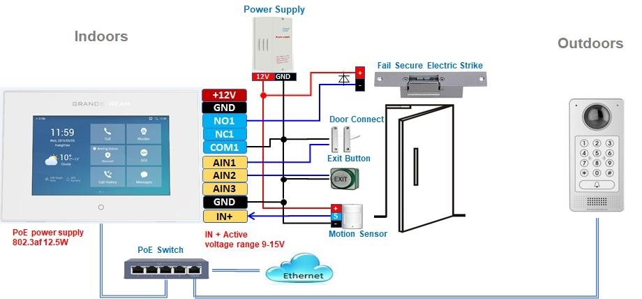
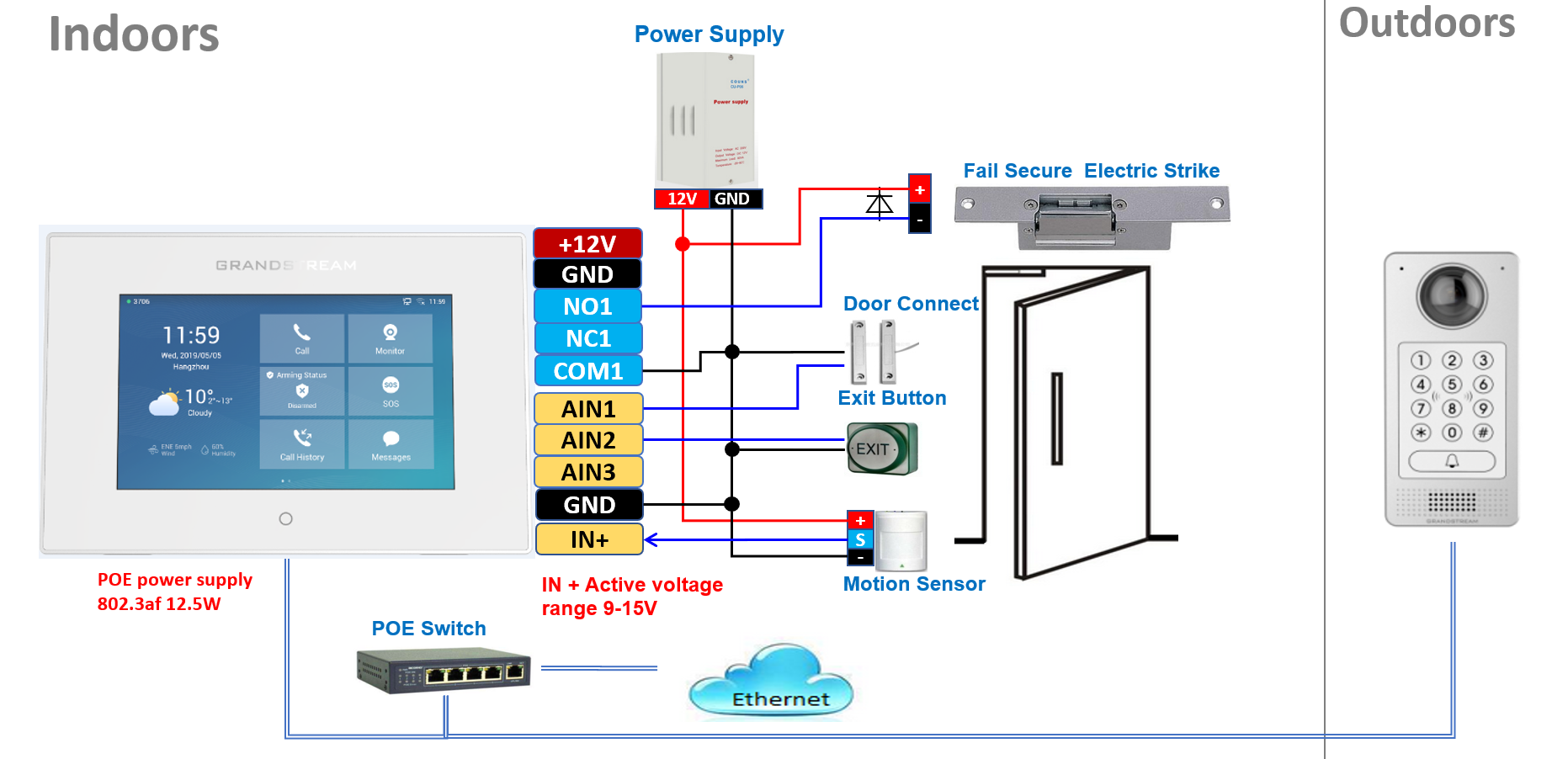
Wiring Diagram – “Fail Secure” Electric Strike, PoE Power Supply
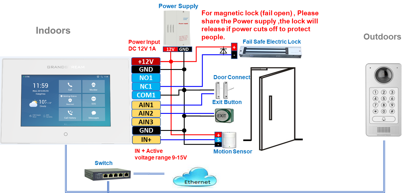
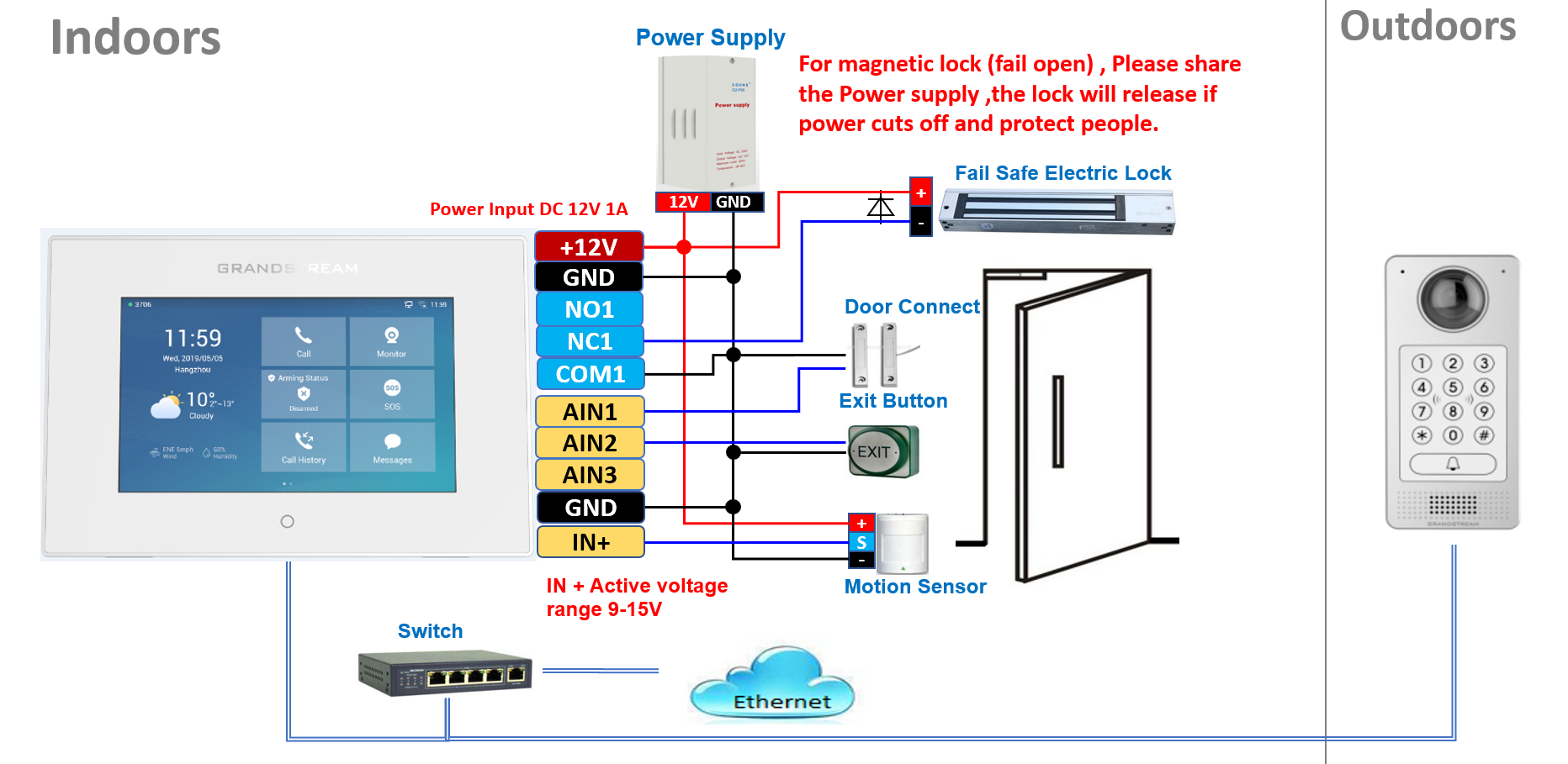
Wiring Diagram – “Fail Secure” Electric Lock, 3rd Party Power Supply
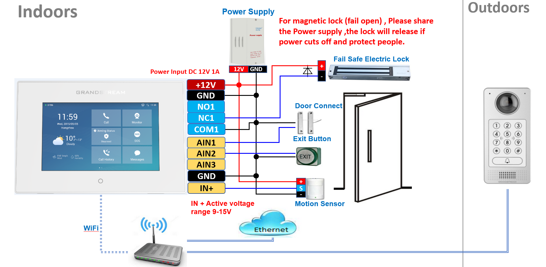
 Wiring Diagram – “Fail Secure” Electric Strike, PoE Power Supply, Wi-Fi
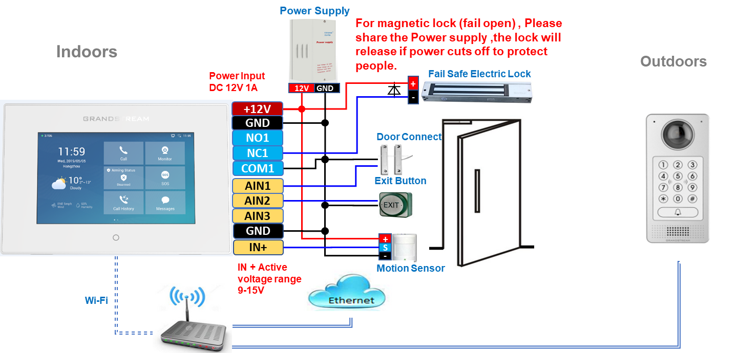 Wiring Diagram – “Fail Secure” Electric Strike, PoE Power Supply, Wi-Fi
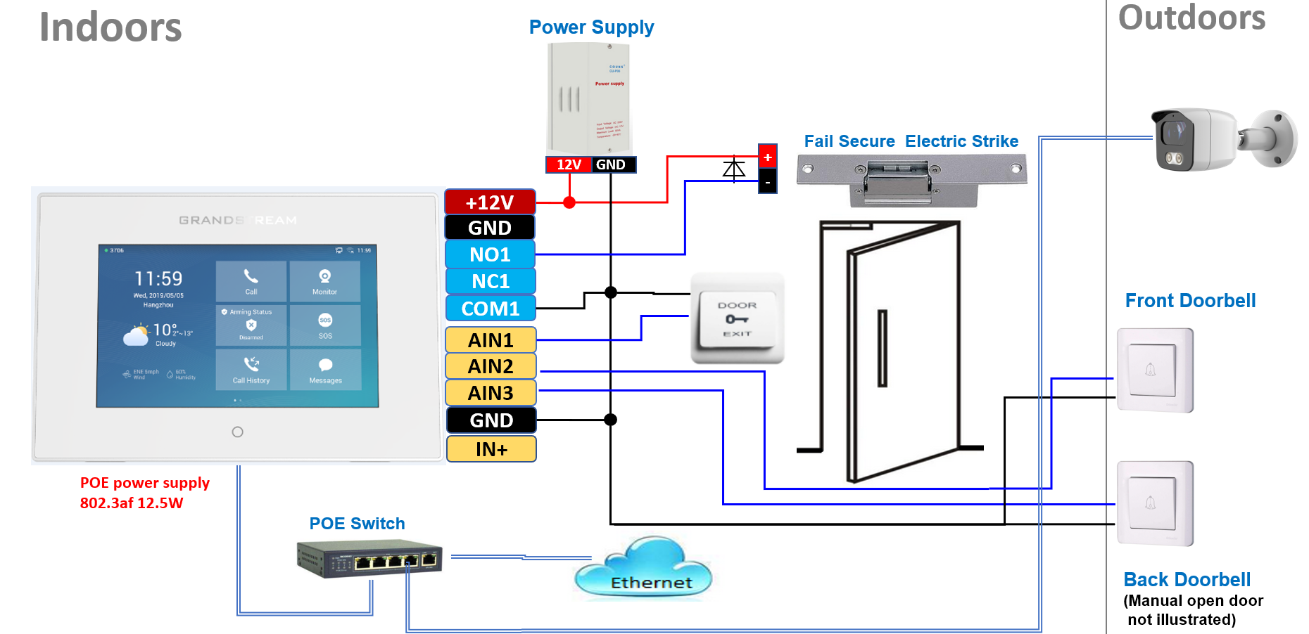
Secure Open Door Wiring
• GSC3570 Inside
• GDS37xx Outside
• Other accessories/sensors
GSC3570 Connection & Wiring Diagrams – “Fail Secure” Electric Strike, POE Power Supply
GSC3570 Connection & Wiring Diagrams – “Fail Safe” Electric lock, 3rd Party Power Supply
GSC3570 Connection & Wiring Diagrams – “Fail Safe” Electric lock, 3rd Party Power Supply, WiFi
GSC3570 Connection & Wiring Diagrams – “Fail Secure” Electric Strike, POE Power Supply
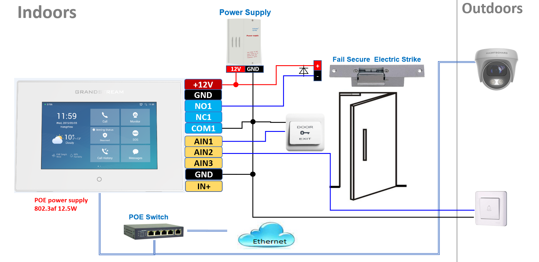
GSC3570 as Upgraded Doorbell and Door Opener
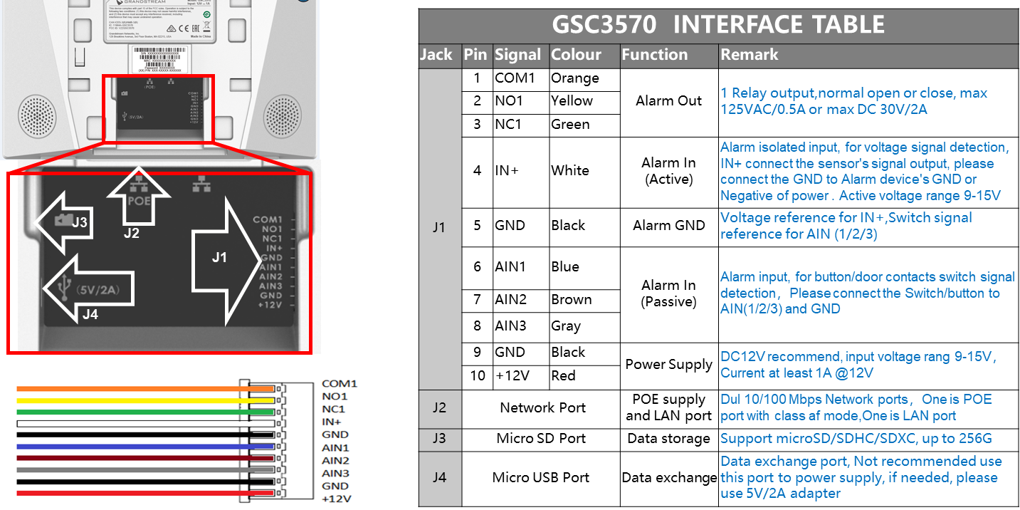
GSC3570 Interface table
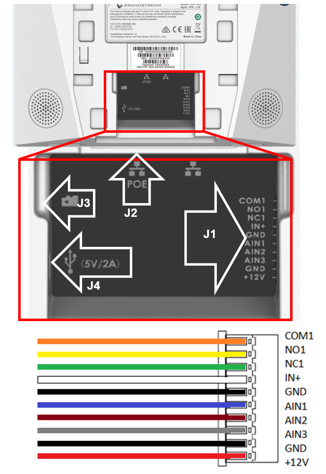
GSC3570 INTERFACE TABLE | |||||
Jack | Pin | Signal | Colour | Function | Remark |
J1 | 1 | COM1 | Orange | Alarm Out | 1 Relay output,normal open or close, max 125VAC/0.5A or max DC 30V/2A |
2 | NO1 | Yellow | |||
3 | NC1 | Green | |||
4 | IN+ | White | Alarm In (Active) | Alarm isolated input, for voltage signal detection,IN+ connect the sensor's signal output, please connect the GND to Alarm device's GND or Negative of power . Active voltage range 9-15V | |
5 | GND | Black | Alarm GND | Voltage reference for IN+,Switch signal reference for AIN (1/2/3) | |
6 | AIN1 | Blue | Alarm In (Passive) | Alarm input, for button/door contacts switch signal detection,Please connect the Switch/button to AIN(1/2/3) and GND | |
7 | AIN2 | Brown | |||
8 | AIN3 | Gray | |||
9 | GND | Black | Power Supply | DC12V recommend, input voltage rang 9-15V,Current at least 1A @12V | |
10 | +12V | Red | |||
J2 | Network Port | POE supply and LAN port | Dual 10/100 Mbps Network ports,One is POE port with class af mode,One is LAN port | ||
J3 | Micro SD Port | Data storage | Support microSD/SDHC/SDXC,up to 256G | ||
J4 | Micro USB Port | Data exchange | Data exchange port, Not recommended use this port to power supply, if needed, please use 5V/2A adapter | ||