


OVERVIEW
The GSC3574/3575 is a powerful intercom and facility control station designed to provide businesses with a dedicated device to manage facility communications, door access, physical security and more. This device can be wall-mounted as a solution for easy door control, intercom and paging communication, security camera management and facility-wide UC integration.
The GSC3574/3575 features a 7-inch touch screen LCD and full duplex 2-way HD audio. lt offers a flexible network connectivity through 100Mbps network port with PoE or integrated dual-band Wi-Fi 6 support. This SIP intercom and facility control station is designed to seamlessly integrate with Grandstream’s entire range of products, including the GDS series of door access devices, GSC series intercom and paging devices, security cameras and more.
The GSC3574/3575 is ideal for any deployment scenario where facility access, communications and security need to be centrally monitored and controlled.
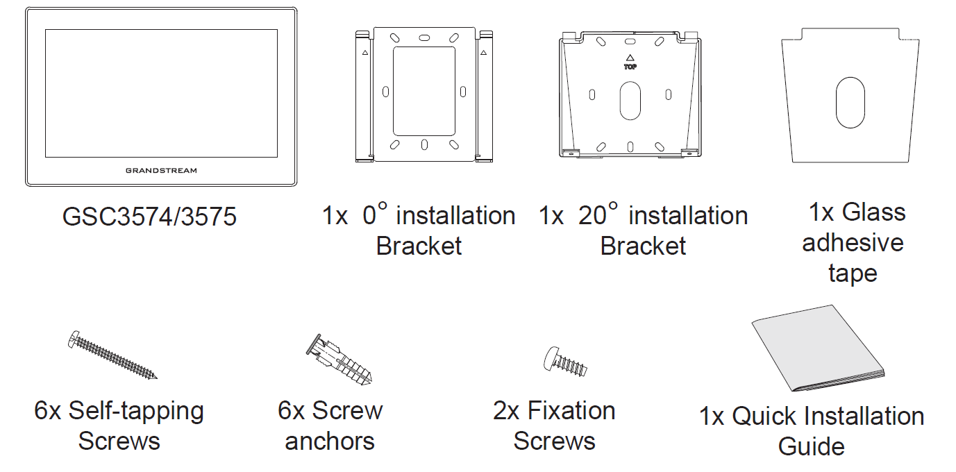
PACKAGE CONTENTS
GSC3574/3575 SETUP
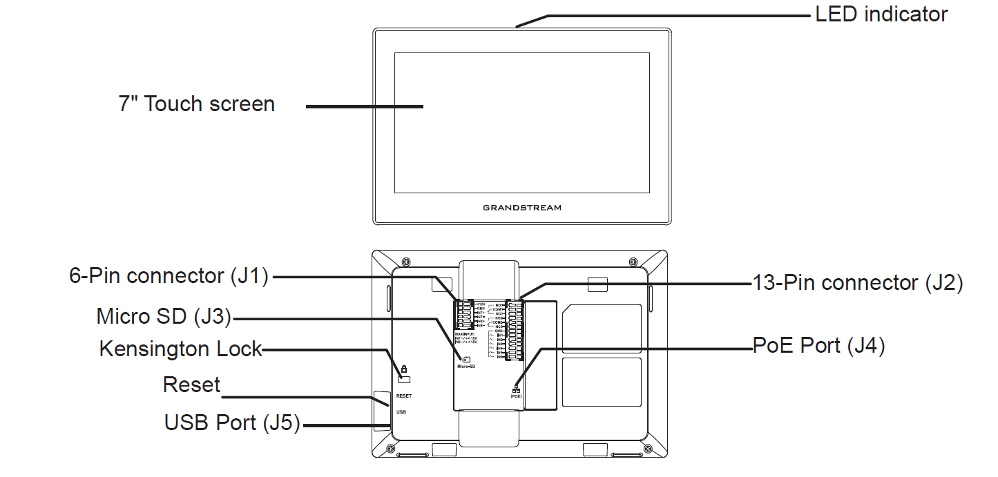
DEVICE INSTALLATION
The GSC3574/3575 can be mounted on the wall, the glass, or on the desktop using a 20 ° bracket . Please refer to the following steps for installation:
On-Wall 0° Mount
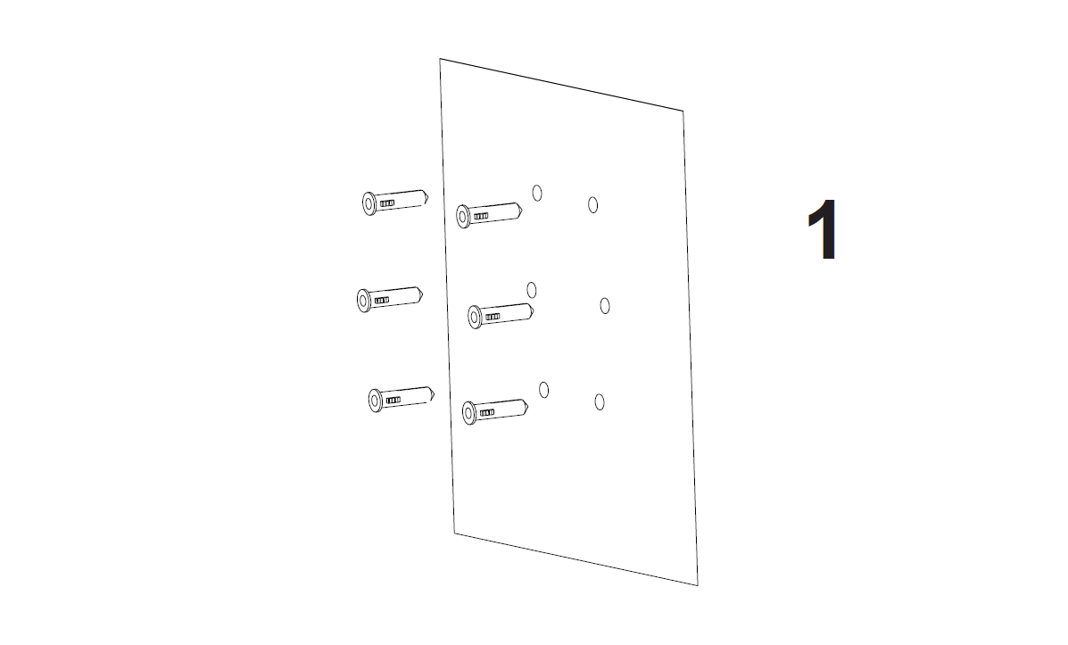
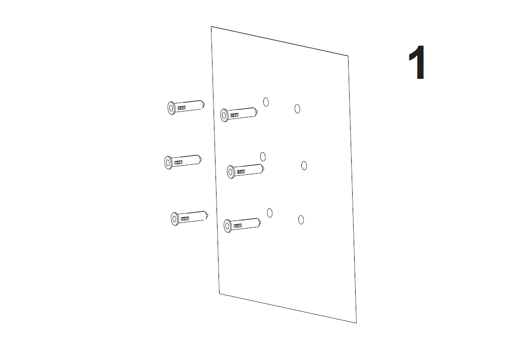
- Drill six holes on the wall referring to the positions of the ones on the 0° installation bracket, then put the screw anchors on the position of the holes.
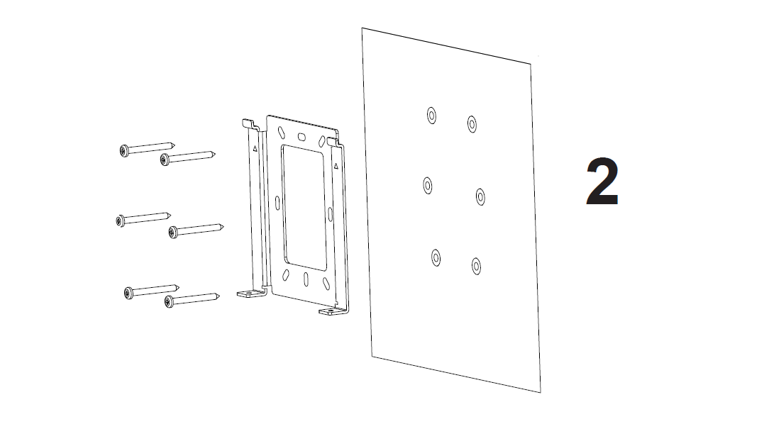
- Fix the 0° installation bracket on the wall by the self-tapping screws on the positions defined.
- Make sure the 0° installation bracket is installed properly as shown in the illustration.
- Plug in the cables to the proper GSC3574/3575 ports on the back, and fix the 0° installation bracket with the GSC3575/74 device using the two fixation screws from the bottom of the device.
- Align the position slots on device’s back with their correct placement on the metal bracket, then fix it by pushing down.
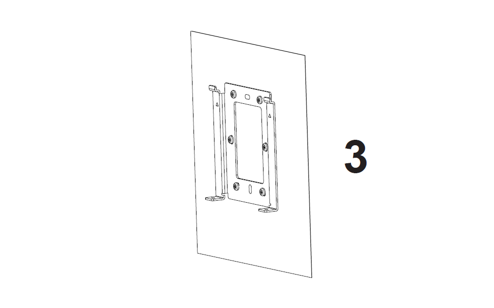
On-Wall 20° Mount
- Drill six holes on the wall referring to the positions of the ones on the 20° installation bracket, then put the screw anchors on the position of the holes.
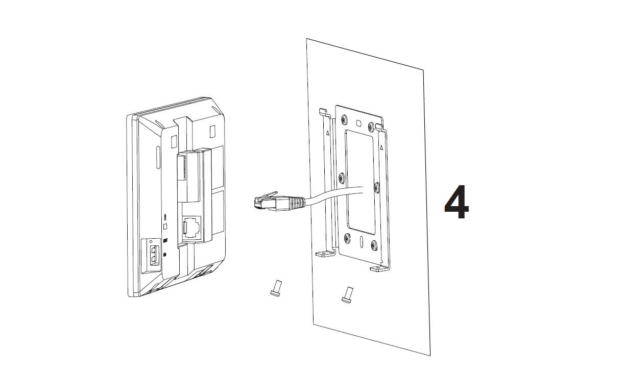
- Fix the 20° installation bracket on the wall by the self-tapping screws on the positions defined.
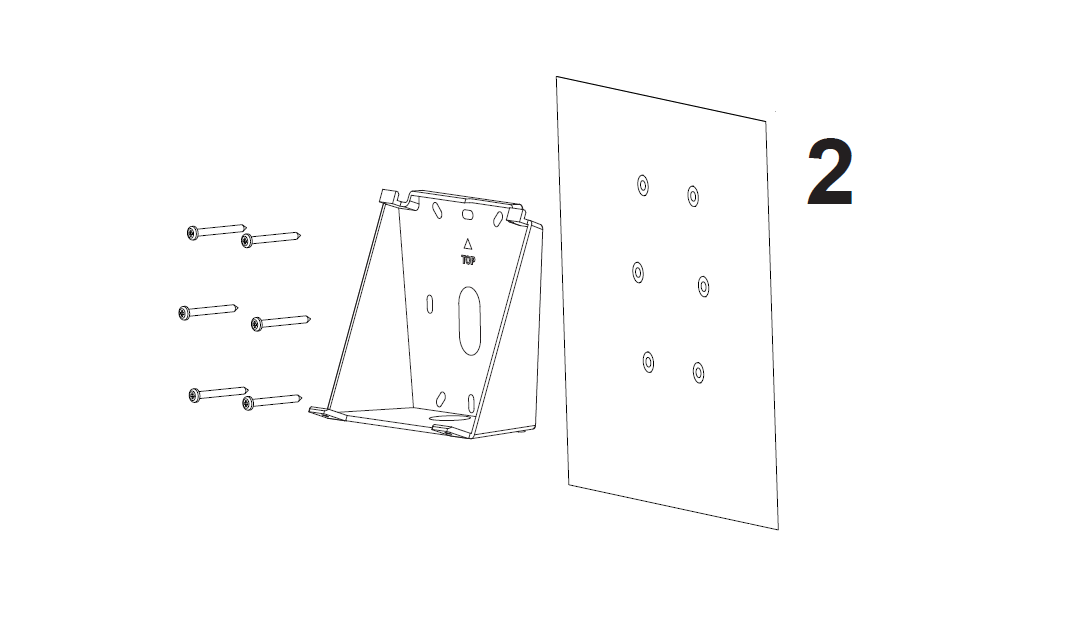
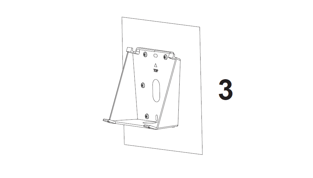
- Make sure the 20° installation bracket is installed properly as shown in the illustration.
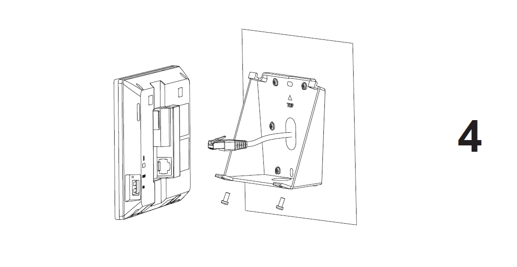
- Plug in the cables to the proper GSC3574/75 ports on the back, and fix the 20° installation bracket with the GSC3575/74 device using the two fixation screws from the bottom of the device.
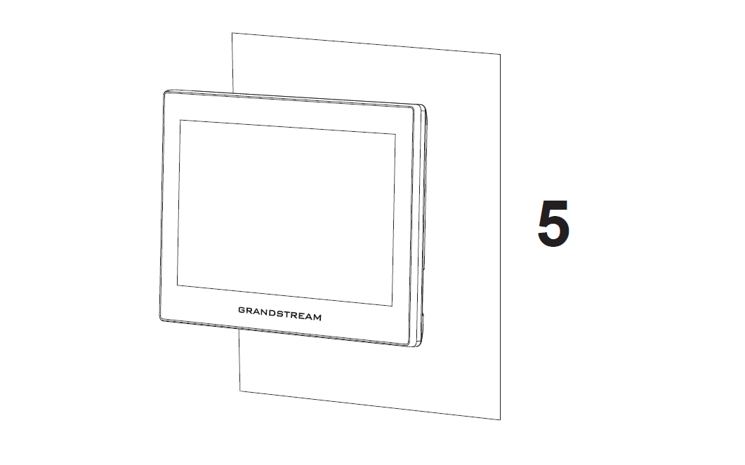
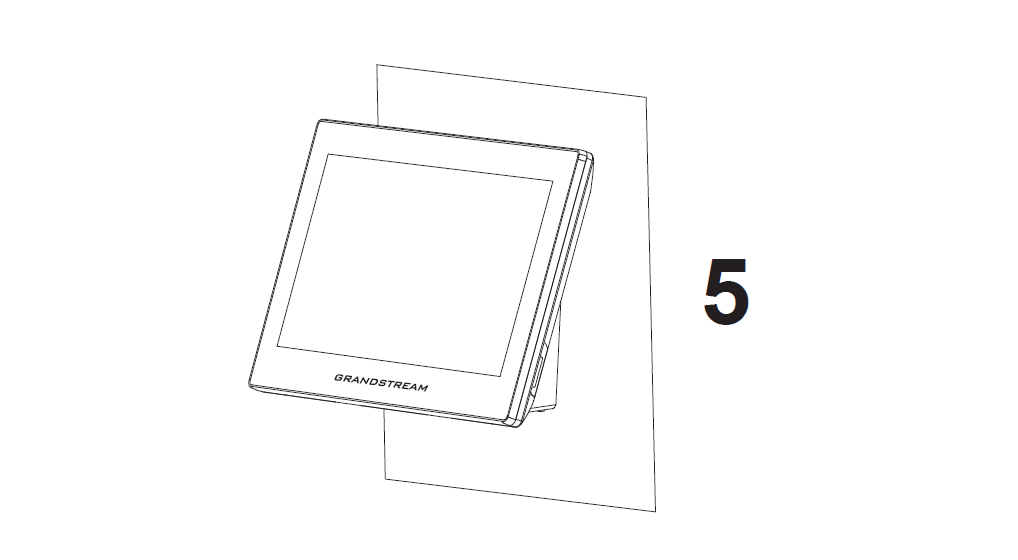
- Align the position slots on device’s back with their correct placement on the 20° installation bracket, then fix it by pushing down.
On-Wall Glass Adhesive Mount
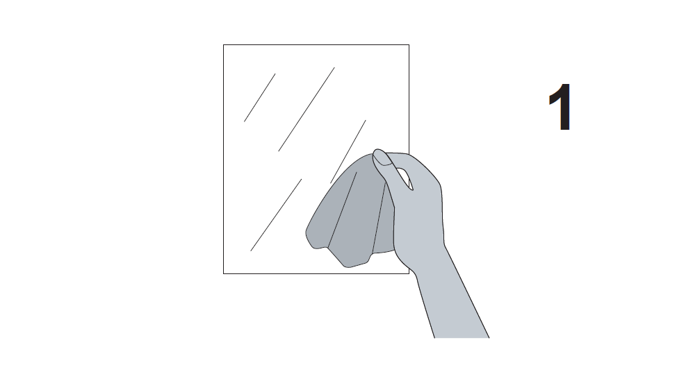
- Clean the glass before installation.
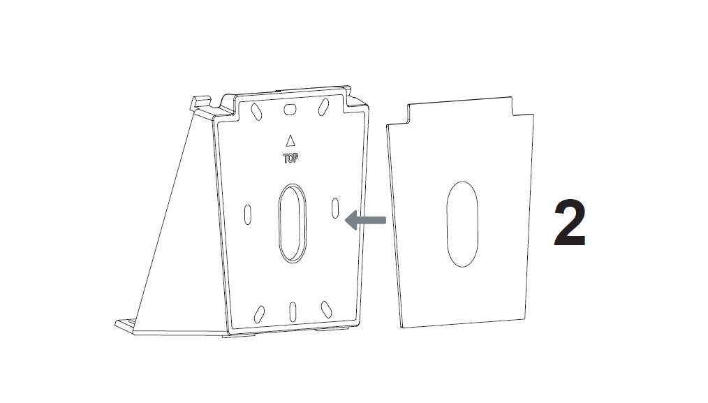
- Stick the Glass Adhesive tape to the 20° installation bracket.
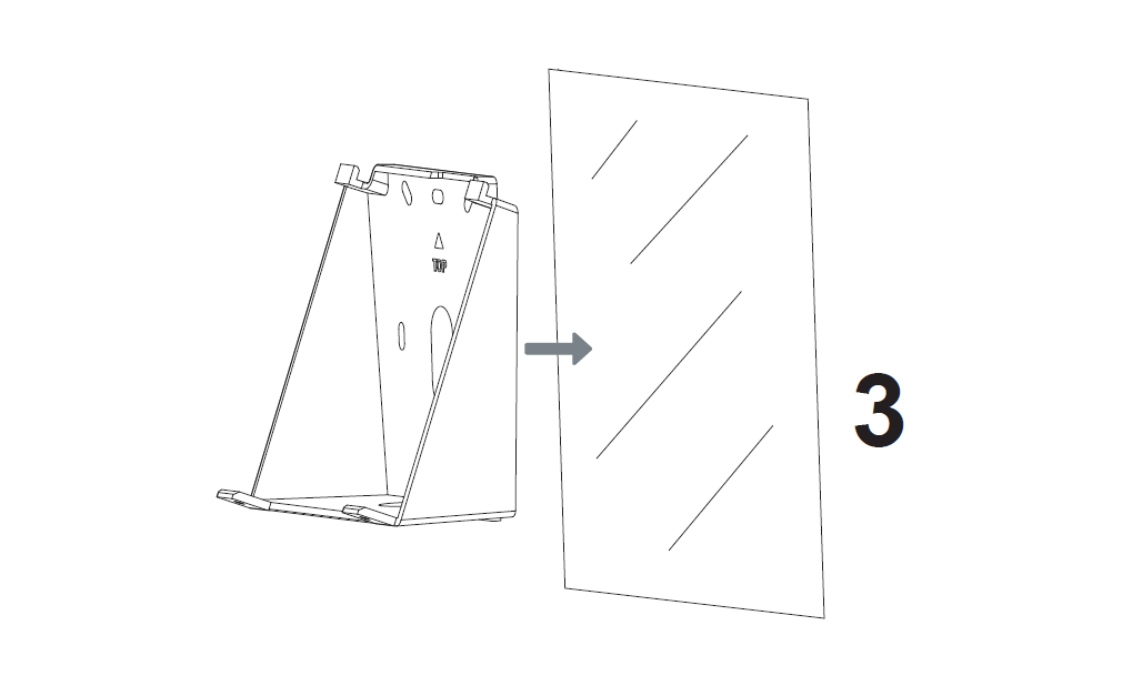
- Install the 20° installation bracket with its glass adhesive tape on the glass.
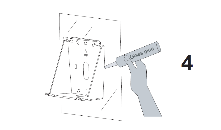
- After installing with double-sided adhesive, please use additional adhesive to fix the equipment.
- Plug in the cables to the proper GSC3574/75 ports, and fix the 20° installation bracket with the GSC3575/74 device using the two fixation screws.
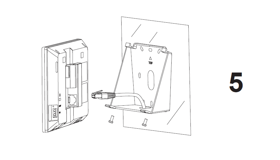
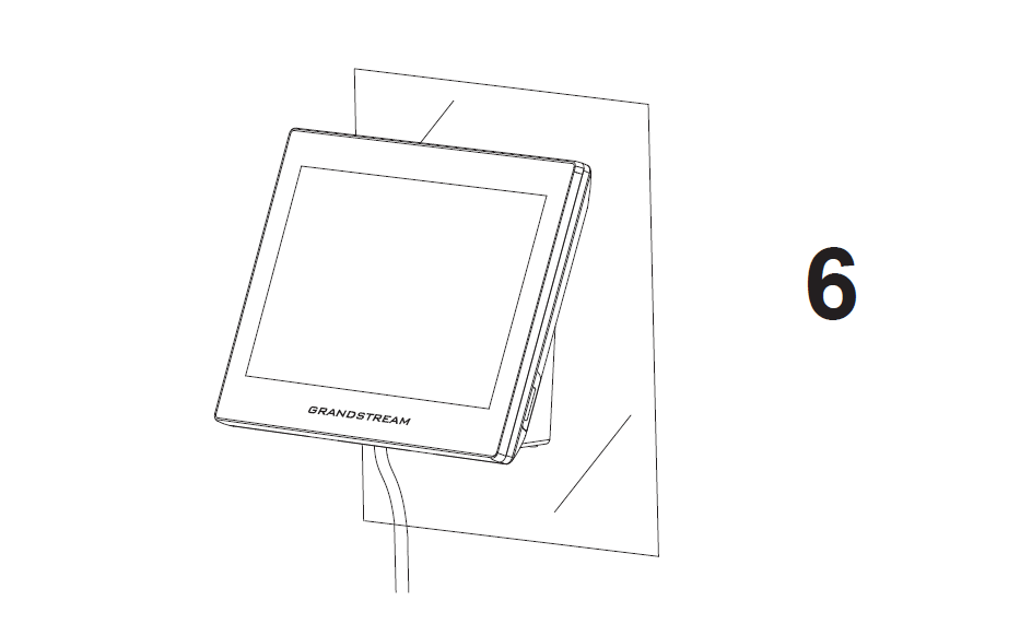
- Align the position slots on device’s back with their correct placement on the 20° installation bracket, then fix it by pushing down.
GSC3574/3575 PORTS
Jack | Port | Function | Remark | |
Pin | Signal | |||
J1 | 1 | IN8- | Alarm IN8(Active) | Isolation type alarm input, used for voltage signal detection, IN+ connected to positive signal output of sensor, IN- connected to negative signal output of sensor or GND of sensor. The active voltage range is 9-15V. |
2 | IN8+ | |||
3 | IN7- | Alarm IN7 (Active) | ||
4 | IN7+ | |||
5 | GND | Power Supply | DC12V recommend, input voltage rang 11-13V, current at least 1.5A@12V. | |
6 | +12V | |||
J2 | 1 | NO1 | Alarm OUT1 | Relay output, normal open or close, max 125VAC/0.5A or max 30VDC/2A. |
2 | COM1 | |||
3 | NC1 | |||
4 | NO2 | Alarm OUT2 | ||
5 | COM2 | |||
6 | NC2 | |||
7 | GND | Alarm IN GND | Voltage reference for IN (1/2/3/4/5/6). | |
8 | IN1 | Alarm IN1(Passive) | Alarm input, used to connect devices such as buttons/ switches/ alarm sensors. | |
9 | IN2 | Alarm IN2(Passive) | ||
10 | IN3 | Alarm IN3(Passive) | ||
11 | IN4 | Alarm IN4(Passive) | ||
12 | IN5 | Alarm IN5(Passive) | ||
13 | IN6 | Alarm IN6(Passive) | ||
J3 | Micro-SD Port | Data Storage | Support microSD/SDHC/SDXC, up to 512G. | |
J4 | Network Port (PoE) | Ethernet & PoE Supply | Single 10/100 Mbps Network port, support 802.3 af POE power supply. | |
J5 | USB Port | Data Exchange (USB 2.0) | The USB port can be connected to USB disk (up to 2TB) / mouse/ keyboard. The default current limit is 460mA, and user can configure it to 1000mA through the web. | |
GSC3574/3575 CONFIGURATION
Configure the GSC3574/3575 Using a Web Browser
- Ensure your device is powered up and connected to the Internet.
- Press “Settings” on Home Page.
- Select “Network Status” to check the IP address.
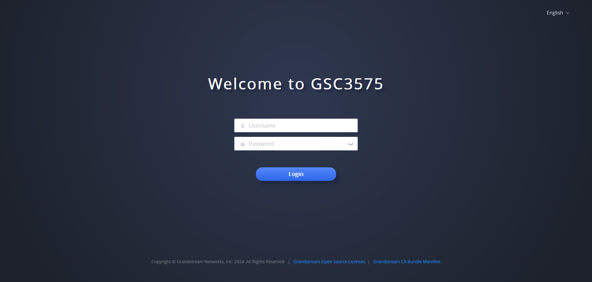
- Type the unit’s IP address in your PC browser. (See figure below).
- Enter admin’s username and password to access the configuration menu. (The factory default username is “admin” while the default random password can be found on the sticker at the back of the unit).

For Certification, Warranty and RMA information, please
visit www.grandstream.com