The GWN7000 is a powerful enterprise-grade router and manager for wireless access points. Ideal for enterprises, office buildings, retail stores, shopping centers, hotels, hospitals, convention centers and more, the GWN7000 allows businesses to build comprehensive Wi-Fi or VPN Networks via many wireless access points that can be shared across many different physical locations.
The GWN7000 can act as controller and manage 300+ GWN76XX Wireless Access Points offering simultaneous dual-band Wi-Fi (2.4GHz and 5GHz) using the latest MIMO 802.11ac technology to maximize bandwidth, increase signal strength and expand Wi-Fi coverage.
This guide contains necessary steps to connect and configure GWN7000 as controller for GWN76XX including discovery, pairing, and managing Wi-Fi network groups and SSIDs.
CONNECTING AND ACCESSING GWN7XXX
Connecting to GWN7000 and GWN76XX
To set up the GWN7000 and the GWN76XX, follow the steps below:
- Connect one end of an RJ-45 Ethernet cable into the WAN1 or/and WAN2 port(s) of the GWN7000.
- Connect the other end of the Ethernet cable(s) into a DSL modem or router(s).
- Connect the 12V DC power adapter into the power jack on the back of the GWN7000. Insert the main plug of the power adapter into a surge-protected power outlet.
- Wait for the GWN7000 to boot up and connect to internet/network. In the front of the GWN7000 the Power LED will be in solid green, and the WAN LED will flash in green.
- Connect one of the LAN ports to your computer, the associated LED ports will flash in green.
- Connect LAN ports to your GWN76XX access points or/and other devices, the associated LED ports will flash in green as displayed on the following diagram.
Access WEB GUI
The GWN7000 embedded Web server responds to HTTPS GET/POST requests. Embedded HTML pages allow users to configure the device through a Web browser such as Microsoft IE, Mozilla Firefox, Google Chrome and etc.
To access the GWN7000 Web GUI, please refer following steps:
- Connect a computer to a LAN Port of the GWN7000.
- Ensure the device is properly powered up, and the Power, LAN port LEDs light up in green.
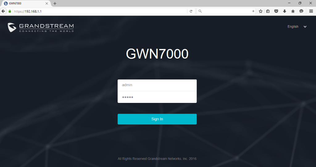
- Open a Web browser on the computer and enter the web GUI URL in the following format:
https://192.168.1.1 - Enter the administrator’s login and password to access the Web Configuration Menu. The default administrator’s username and password are “admin” and “admin”.
Note:
MANAGING WI-FI NETWORK USING GWN76XX
The GWN7000 Enterprise Router provides users capability to create a wireless network by adding multiple GWN7600 series access points using the most common wireless standards (802.11b/g/n) operating in both 2.4GHz and 5GHz range. GWN7000 can manage up to 300 GWN76XX Access Points.
On this chapter, we will describe in depth how to discover and add the GWN76XX Access Point to GWN7000 Router and how create / manage Wi-Fi zones.
Power and Connect GWN76XX Access Point
- Connect one end of a RJ-45 Ethernet cable into the NET or PoE/NET port of the GWN76XX.
- Connect the other end of the Ethernet cable(s) into a LAN port of the GWN7000 Router (or to a switch connected into LAN port of the GWN7000 router so that the access point becomes the LAN client of the GWN7000 router).
- Connect the 24V DC power adapter into the power jack on the back of the GWN76XX and insert the main plug of the power adapter into a surge-protected power outlet.
Notes:
Discover and Pair GWN76XX Access Point
The GWN76XX is a powerful access point which is fully compatible with the GWN7000 and can be added, provisioned and managed in an easy and intuitive way using the web GUI of the GWN7000 router. Once the GWN76XX is successfully connected and has an IP from the GWN7000 router, users can then pair it to the GWN7000 and associate it with a Wireless Zone.
To pair the GWN76XX access point, please refer to following steps:
- Access the GWN7000 Web GUI using the administrator username and password. (Default username / password are: admin/admin)
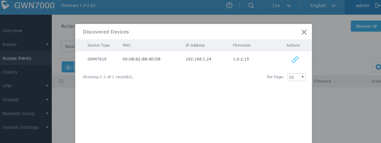
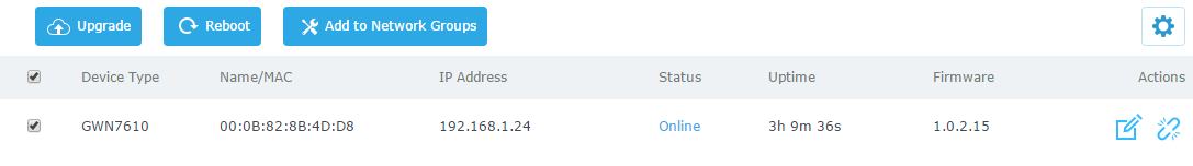
- Navigate to Access Points page which list and display available GWN76XX access points.
- Clicks on Discover AP button
 to display discovered access points within GWN7000’s Network as displayed on following screenshot.
Note:

- Click
 for the selected device to pair it with GWN7000 Router.
Notes:


Note:
GWN76XX Access Point Configuration
The GWN76XX access point can be easily managed and configured from the GWN7000 Web GUI. The GWN7000 acts as controller for all paired GWN76XX access points.
To configure the paired GWN76XX access point, please refer to following steps:
- Access the GWN7000 Web GUI using the administrator username and password. (Default username / password are: admin/admin)
- Navigate to Access Points page which list and display available / paired GWN76XX access points.
- Select the desired access point and click on Edit
 button under Actions to access GWN76XX Device Configuration which combine the status, users and configuration settings of the GWN76XX access point.

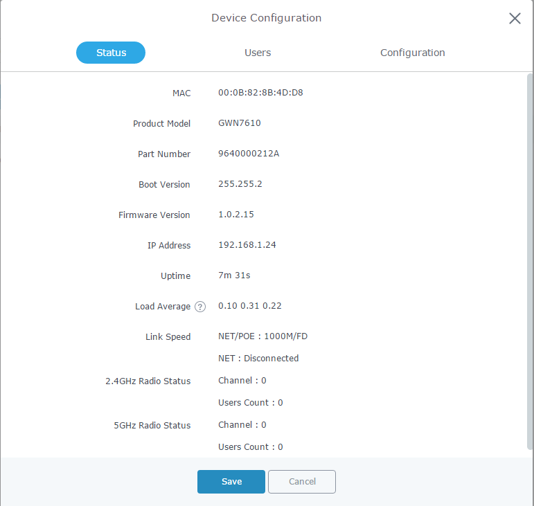
The following table describes GWN76XX Access Point configuration settings:
Status | Shows the device’s status information such as Firmware version, IP Address, Link Speed, Uptime, and Users count via different Radio channels. |
Users | Shows the users connected to the GWN76XX access point. |
Configuration |
Set GWN76XX’s name to identify it along with its MAC address.
Used to set a static IP for the GWN76XX, if checked users will need to set the following: 1. IPv4 AddressEnter the IPv4 address to be set as static for the device. 2. IPv4 Subnet MaskEnter the Subnet Mask. 3. IPv4 Gateway Enter the Network Gateway’s IPv4 Address. 4. Preferred IPv4 DNSEnter the Primary IPv4 DNS. 5. Alternate IPv4 DNSEnter the Alternate IPv4 DNS.
Set the GWN76XX’s frequency, it can be either 2.4GHz, 5GHz or Dual band.
When Frequency is set to Dual-Band, users can check this option to enable Band Steering on the Access Point. This will help redirecting clients to a radio band accordingly for efficient use and to benefit from the maximum throughput supported by the client.
Choose the mode for the frequency band, 802.11n/g/b for 2.4Ghz and 802.11ac for 5Ghz.
Choose the Channel Width, note that wide channel will give better speed/throughput, and narrow channel will have less interference. 20Mhz is suggested in very high-density environment.
Configure the 40MHz channel location when using 20MHz/40MHz in Channel Width, users can set it to be “Secondary Below Primary”, “Primary Below Secondary” or “Auto”.
Select “Auto” or a specific channel. Default is “Auto”. Note that the proposed channels depend on Country Settings under System Settings–>Maintenance.
Check to activate this option to increase throughput.
Choose active spatial stream. Available options: “Auto”, “1 stream”, “2 streams” and “3 streams” (For GWN7610).
Set the Radio Power depending on desired cell size to be broadcasted, three options are available: “Low”, “Medium” or “High”. Default is “High”. |
MANAGING GROUPS AND SSIDs
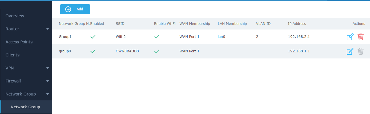
Network Groups
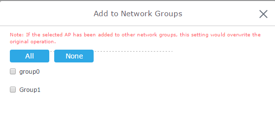
Users can create different Network groups separated by VLANs and adding paired GWN76XX Access Points.
Following steps describe in depth how to add / manage existing network groups:
- Access the GWN7000 Web GUI using the administrator username and password. (Default username / password are: admin/admin)
- Access to Network Group-> Network Group.
Note:
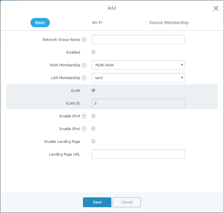
When editing or adding a new network group, users will have three tabs for configuration:
- Basic: Used to name the network group, and set a VLAN ID if adding a new network group, and addressing plans, refer to below table for each field:
Network Group Name | Specifies the name for the network group. |
WAN Membership | Select the WAN port membership. Users can benefit from multi-WAN option if enabled under Router->Port->Global Settings. |
LAN Membership | Select the LAN port membership. |
VLAN | Check to enable VLAN. This field is appearing only when having more than a network group. |
VLAN ID | Set a VLAN ID. Valid range is between 2 and 4093. |
Enable IPv4 | Check to enable IPv4 addressing for this network group. |
IPv4 Static Address | Set a static IPv4 address for the network group when enabling IPv4. |
IPv4 Subnet Mask | Set the Subnet Mask. |
DHCP Enabled for IPv4 | Check to enable DHCP using IPv4. This will allow clients connected to this network group to get IPv4 addresses automatically from GWN7000 acting as DHCP server. |
DHCP Start Address | Set the starting IPv4 address for this network group’s clients. |
DHCP End Address | Set the ending IPv4 address for this network group’s clients. |
DHCP Lease Time | Set the lease time for DHCP clients users can set the value in hours, minutes, or as “infinite”. Default lease time is “12h”. |
DHCPv4 Options | Set the DHCP options. Click on Example: 44,192.168.2.50 for DHCP option 44 and 192.168.2.50 is the WINS server’s address. Please refer to the following link for DHCP options syntax: https://wiki.openwrt.org/doc/howto/dhcp.dnsmasq |
DHCPv4 Relay Enabled | Enable this option, if you want the GWN7000 relays the DHCP requests from clients to another DHCP server(s). Once checked Click on |
Enable IPv4 | Check to enable IPv6 addressing for this network group. |
IPv6 Relay from WAN | Check to allow GWN7000 to relay IPv6 DHCP request from network group’s clients to WAN port. |
DHCP Enabled for IPv6 | Check to enable IPv6 DHCP server for this network group. |
IPv6 Prefix for Assignment | Set the prefix value to be assigned to the network group. Valid range is between 1 to 64. Example: 64 will assign /64 prefixes. |
IPv6 Subnet Hint | Set the subnet mask value. |
IPv6 Uplink | Select the WAN port. |
Enable Landing Page | Check to enable landing page when connecting to this network group’s Wi-Fi. |
Landing Page URL | Set the landing page URL to which clients will be redirected once connected to the network group’s Wi-Fi. |
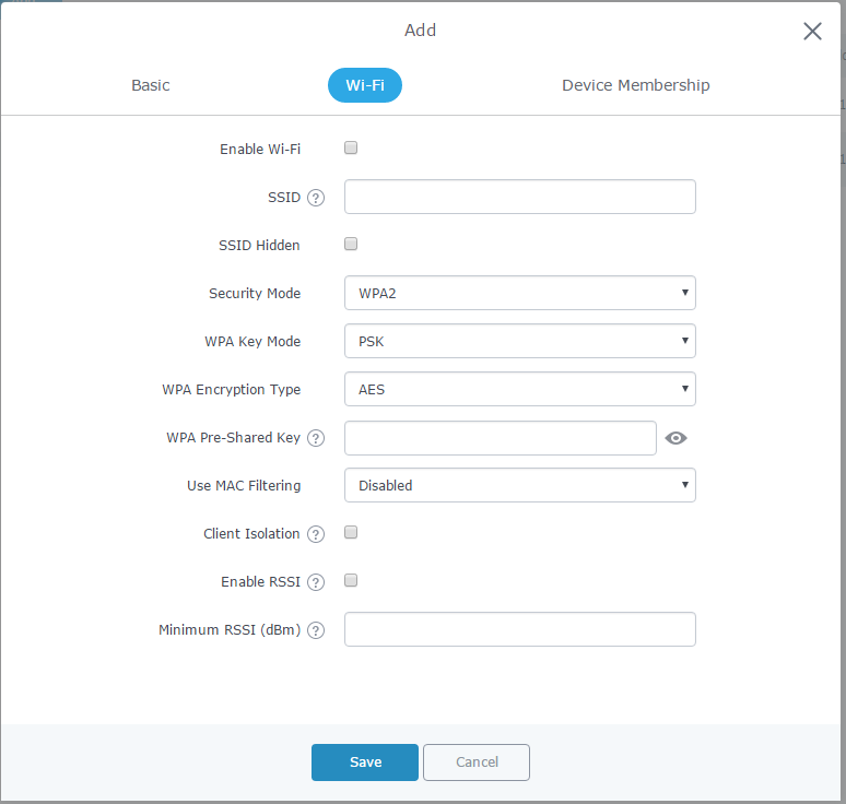
- Wi-Fi: Please refer to the below table for Wi-Fi tab options:

Enable Wi-Fi | Check to enable Wi-Fi for the network group. |
SSID | Set or modify the SSID name. |
SSID Hidden | Select to hide SSID. SSID will not be visible when scanning for Wi-Fi, to connect a device to hidden SSID, users need to specify SSID name and authentication password manually. |
Security Mode | Set the security mode for encryption, 5 options are available:
|
Use MAC Filtering | Choose Blacklist/Whitelist to specify MAC addresses to be excluded/included from connecting to the zone’s Wi-Fi. Default is Disabled. |
Client Isolation | Choose if client isolation will be enabled in order to forbid wireless clients connected to the zone’s Wi-Fi from seeing each other. If enabled users will need to specify the Gateway’s MAC address so users, will not lose access to the Network. |
Gateway MAC Address | Type in the Gateway’s MAC address if using Client Isolation. |
RSSI Enabled | Check to enable RSSI function, this will lead the AP to disconnect users below the configured threshold in Minimum RSSI (dBm). |
Minimum RSSI (dBm) | Enter the minimum RSSI value in dBm. If the signal value is lower than the configured minimum value, the client will be disconnected. The input range is from “-94” or “-1”. |
- Device Membership: Used to add or remove paired access points to the network group.
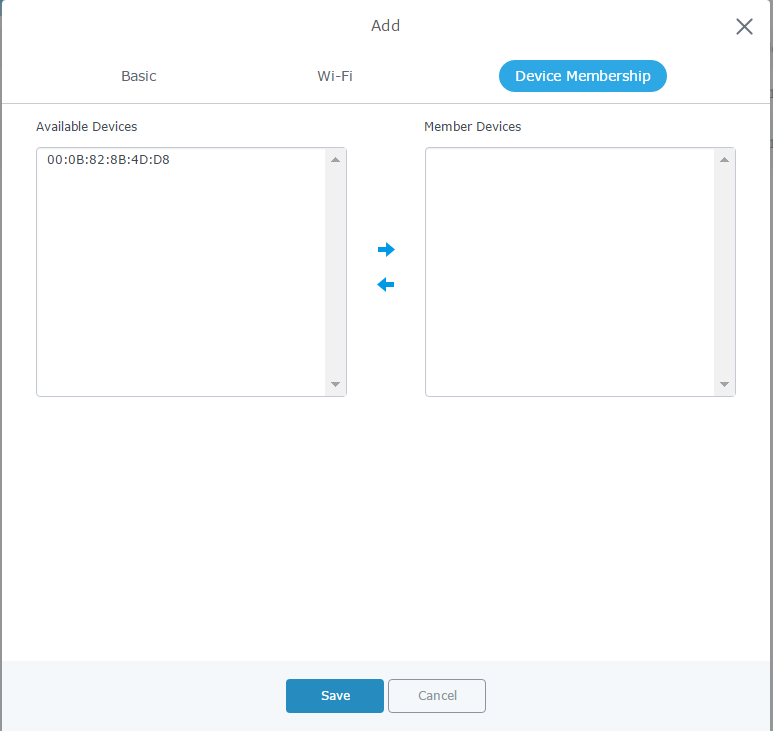
Click on ![]() to add the GWN76XX to the network group, or click on
to add the GWN76XX to the network group, or click on ![]() to remove it.
to remove it.
Note:
SSIDs
Create SSID under Network Group
To create an SSID under a network group, please refer to following steps:
- Under Network Group Page, click to edit a network group or create a new network group.
- Navigate to Wi–Fi tab.
(Please refer to Table 3: Network Group -> Wi-Fi for more details about the Wi-Fi configuration settings.)
Additional SSID under Same Network Group
Users can also create an additional SSID under the same group. To create an additional SSID:
- Access to Network Group->Additional SSID.
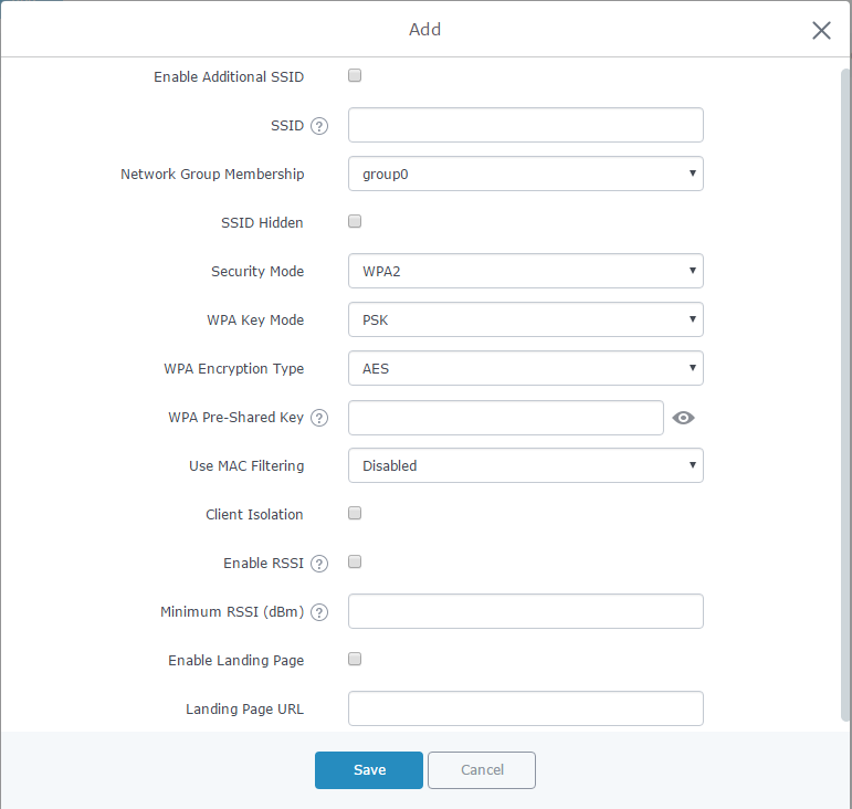
- Select one of the available network groups from Network Group Membership dropdown menu, this will create an additional SSID with the same Device Membership configured when creating the main network group.
Note:

CLIENTS MANAGEMENT
Connected clients to different network groups can be shown and managed from a single interface.
Users can access clients list from GWN7000’s Web GUI -> Clients to perform different actions to wired and wireless clients.
GWN7000 Enterprise Router with its DHCP server enabled on LAN ports level, will assign automatically an IP address to the devices connected to its LAN ports like a computer or GWN76XX access points and to wireless clients connected to paired GWN76XX access points.
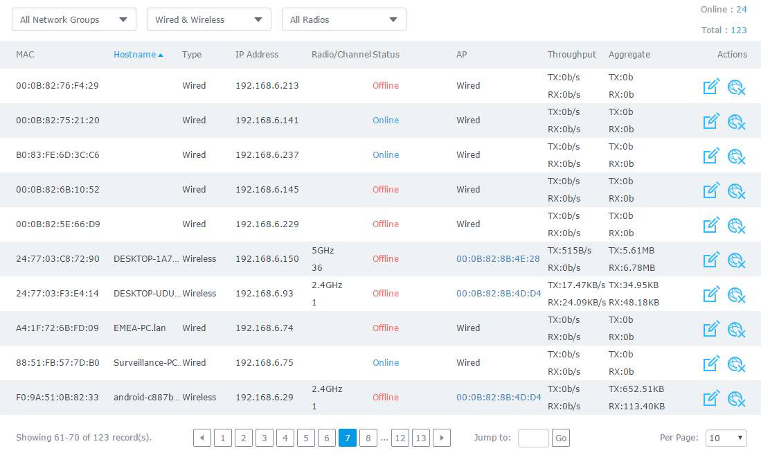
Click on ![]() under Actions to check the client’s status and modify its configuration.
under Actions to check the client’s status and modify its configuration.
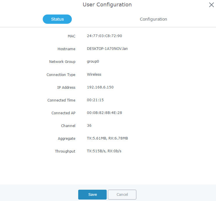
Status
This page allows to check user’s basic information such as MAC address, IP address, which Network group does it belong to, and to which access point if it’s a wireless client, as well as Throughput and Aggregate usage.
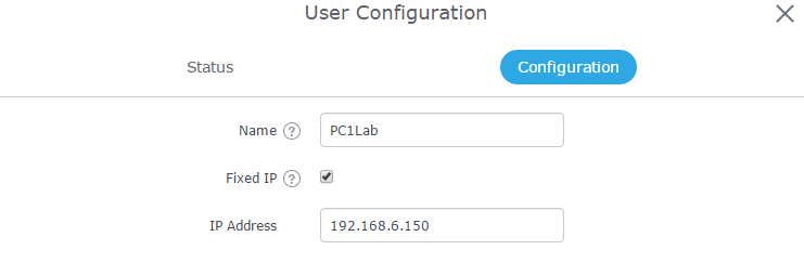
Edit IP and Name
Users can set name for a client and set a static IP.
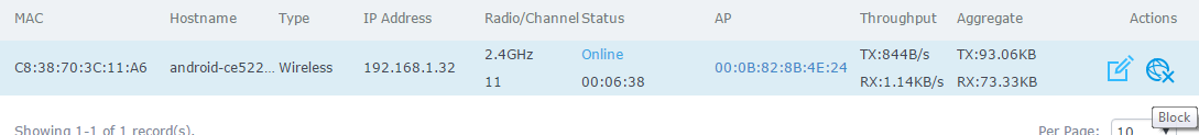
Block Client
To block a client, click on ![]() under actions.
under actions.
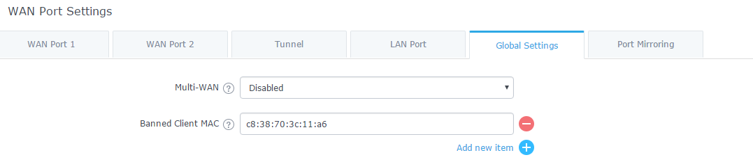
To unban a client, go to Router -> Port -> Global Settings. Click on ![]() to remove it from the banned list.
to remove it from the banned list.
DEPLOYMENT EXAMPLES
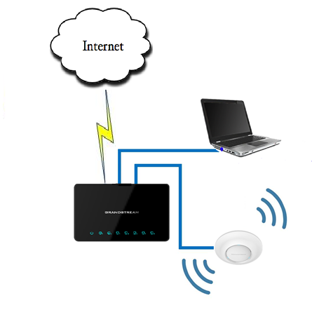
Deployment with Single GWN76XX Access Point
In this scenario, only one GWN76XX Access point is connected to GWN7000 network providing Wi-Fi connection to users. GWN7000 is connected to Internet via its WAN port.
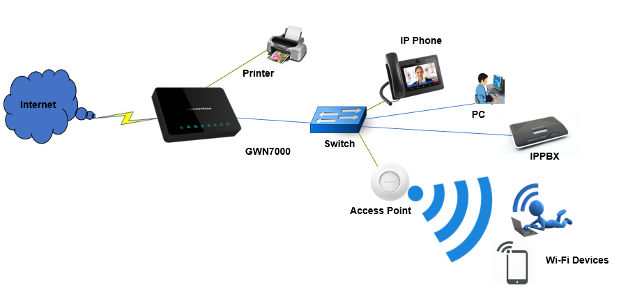
Figure 24: Deployment with Single GWN76XX Access Point
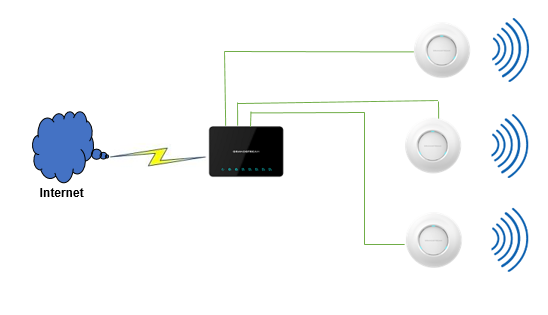
Deployment with Multiple GWN76XX Access Points
In this scenario, multiple GWN76XX Access points are connected to GWN7000 network (either directly or via a switch) providing Wi-Fi connection to users. GWN7000 is connected to Internet via its WAN port.
GWN7000 can manage up to 300 GWN76XX Access Points.