
QoS (Quality of Service) allows prioritizing data, slowing down less important data to allow more important or sensitive data to be prioritized first.
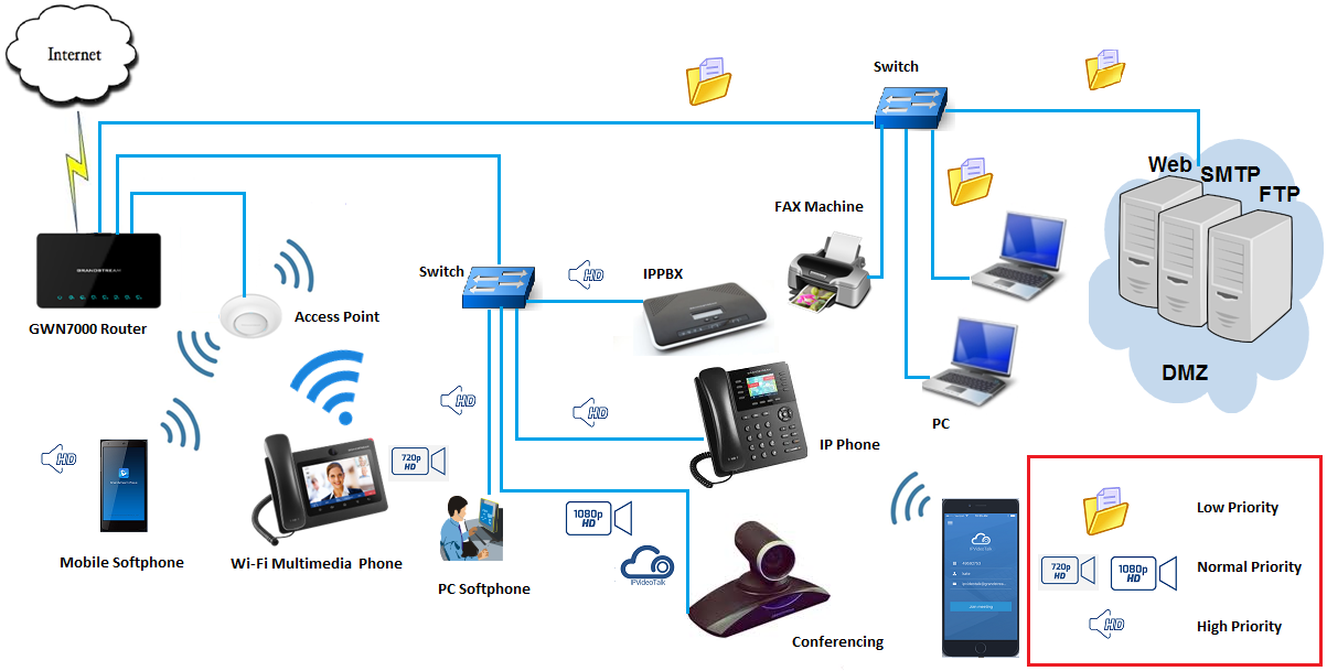
In a network where many devices and services are being provided using the same network resources, QoS can play a very important role to prioritize and reliably deliver certain types of data such as voice or video in favor of file transfers for example.
QoS service uses DCSP classification and can be configured on GWN7000 in different ways; per IP address(es), per port(s), or per Network Groups.
This guide will show how to use GWN7000 in such environments where it is essential to prioritize VoIP traffic over other types of data such as file transfers, HTTP web browsing…etc.
DSCP CLASSIFICATION
Differentiated Services (DiffServ) is a new model in which traffic is treated by intermediate systems with relative priorities based on the type of services (ToS) field. Defined in RFC 2474 and RFC 2475, the DiffServ standard supersedes the original specification for defining packet priority described in RFC 791. DiffServ increases the number of definable priority levels by reallocating bits of an IP packet for priority marking.
The DiffServ architecture defines the DiffServ (DS) field, which supersedes the ToS field to make per-hop behavior (PHB) decisions about packet classification and traffic conditioning functions, such as marking, filtering, and policing.
Refer to the below table for Layer3 and Layer2 classifications regarding the used applications/services.
Application/Service | L3 Classification | L2 Classification | |
Per-Hop-Behavior (PHB) | DSCP | CoS | |
Routing | CS6 | 48 | 6 |
Voice | EF | 46 | 5 |
Multimedia Conferencing | AF41 | 34 | 4 |
Multimedia Streaming | CS4 | 32 | 4 |
Mission-Critical Data | 25 | 3 | |
Call Signaling | [AF31 CS3] | [26 24] | 3 |
Transactional Data | AF21 | 18 | 2 |
Network Management | CS2 | 16 | 2 |
Bulk Data | AF11 | 10 | 1 |
Scavenger | CS1 | 8 | 1 |
Best Effort (Default) | 0 | 0 | 0 |
QUALITY OF SERVICE ON GWN7000
The GWN7000 supports 802.1Q, and 802.1p Layer 2 standards allowing the creation of multiple traffic classes, filter by port, IP address, or network groups. Along with the support of DSCP Layer 3 marking and policing features to help shape high downstream traffic.
QoS features are accessible from GWN7000’s WebGUI → Router → QoS
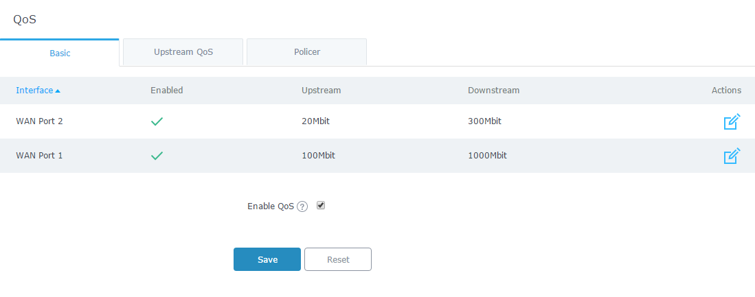
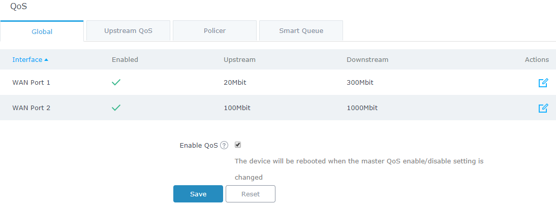
To activate QoS, check “Enable QoS”. Three tabs are available for configuration:
- Global: To configure the download and upload bandwidth speeds settings on each WAN interface.
- Upstream QoS: Upstream QoS allows the creation of Traffic Classes to prioritize traffic for specific resources on the network by controlling transmission/upload rate. Note that different traffic filters can be created and applied to classes to mark the packet with the DSCP value by respecting the following conditions:
- The total Upstream bandwidth values of each created class should not exceed the upstream bandwidth value configured in Global.
- The remaining bandwidth will be lent to the class of traffic with the next priority.
- All filter options are summed together.
- Policer: While Upstream QoS is dealing with traffic transmission, Policer is controlling the incoming traffic. Thus, allowing to create rules to specific targets to set priority and received traffic rate, giving the GWN7000 the ability to drop the exceeding traffic when reaching the configured maximum rate.
The following tables describe each tab option:
|
Enabled |
Check to enable upstream and downstream bandwidth speeds for the selected WAN interface. |
|
Upstream |
Set the upstream value to specify the upload bandwidth for selected interface. The value should end with “Mbit”, “Kbit” or with no unit if the set value is referring to “bit” unit. 100Kbit 500 |
|
Downstream |
Set downstream value to specify the download bandwidth speed for selected interface. The value should end with “Mbit”, “Kbit” or with no unit if the set value is referring to “bit” unit. |
Traffic Class
|
Name |
Define a name for the traffic class. |
|
Priority |
Set the priority of the traffic class. Lower values have higher priority. Valid range is between 1 and 64. |
|
Interface |
Select the WAN interface from which the traffic will be classified. Make sure to enable QoS on the desired interface from “QoS ” in order to appear. |
|
Upstream |
Set Upstream bandwidth value. The value should end with “Mbit”, “Kbit” or with no unit if the set value is referring to “bit” unit. |
|
Class |
Select a class from created traffic classes using drop-down menu. |
|
Name |
Define a Name for the traffic filter rule. |
|
DSCP |
Choose the Differentiated Services Code Point (DSCP) value from drop-down list. Default is 0. |
|
IP Source Address |
Specify the Source IP address from which the traffic filter rule will be applied. |
|
IP Destination Address |
Specify the Destination IP address to which the traffic filter rule will be applied. |
|
TCP Source Port |
Specify the TCP Source port from which the traffic filter rule will be applied. |
|
TCP Destination Port |
Specify the TCP Source port to which the traffic filter rule will be applied. |
|
UDP Source Port |
Specify the UDP Source port from which the traffic filter rule will be applied. |
|
UDP Destination Port |
Specify the UDP Source port to which the traffic filter rule will be applied. |
|
Group Source |
Choose the LAN group of the specified Source IP address. If no Source IP address has been defined, the rule will be applied to all members of that LAN group. |
|
Name |
Define a Name for the Policer rule. |
|
Interface |
Select an interface from which the traffic will be policed. Make sure to enable the desired interface from “QoS ” in order to appear. |
|
Priority |
Set the priority of the traffic class. Lower values have higher priority. Valid range is between 1 and 64. |
|
Rate |
Set a Rate value for download bandwidth when applying policer rule. |
|
DSCP |
Choose the Differentiated Services Code Point (DSCP) value from drop-down list. Default is 0. |
|
IP Source Address |
Specify the Source IP address from which the policer rule will be applied. |
|
IP Destination Address |
Specify the Destination IP address to which the policer rule will be applied. |
|
TCP Source Port |
Specify the TCP Source port from which the policer rule will be applied. |
|
TCP Destination Port |
Specify the TCP Source port to which the policer rule will be applied. |
|
UDP Source Port |
Specify the UDP Source port from which the policer rule will be applied. |
|
UDP Destination Port |
Specify the UDP Source port to which the policer rule will be applied. |
|
Group Source |
Choose the LAN group of the specified Source IP address. If no Source IP address has been defined, the rule will be applied to all members of that LAN group. |
USING QOS TO PRIORITIZE VOIP TRAFFIC
Traffic priority is a way of ensuring that specific applications or sub networks are guaranteed a certain amount of the uplink bandwidth at all times. Traffic priorities only come into play when the network is using all of the pre-configured bandwidth on the uplink.
For VoIP environments, network latency can be a big issue that can be caused by network congestions due to file transfer operations for example. Hence, making audio or video calls very hard to deal with where a delay can make the communication impossible, on the other hand, having a little delay on your downloaded file for example is not very critical to the network.
And since VoIP signaling or voice/video communications are very critical to most Enterprises in the age of Unified Communication, and does not require a very large bandwidth, is it very required to give these types of services a special treatment.
QoS Configuration using IP Address
In this section, we will show how to prioritize traffic for a specific IP within GWN7000 Network.
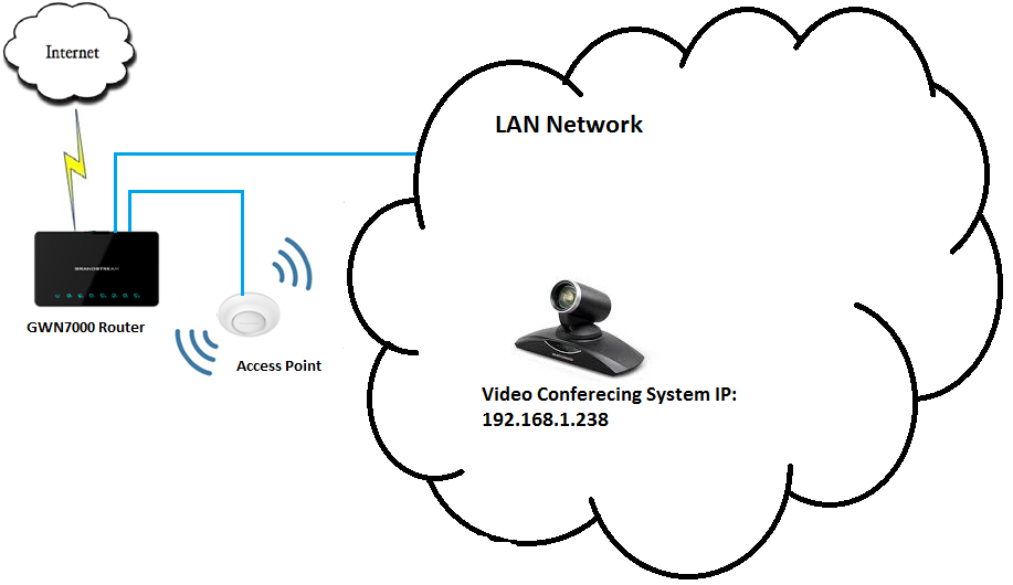
Figure 3: Prioritizing by IP Address
In above example figure, we will prioritize all traffic coming from GVC3200’s IP address (Video Conferencing System) regardless of the service or port used on the conferencing System.

- Supposing that the device is correctly connected to the a GWN7000 Network and has an IP, it is advised to set a static IP for the device in question.
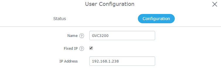
To set a static IP for the device on which traffic need to be prioritized, access to GWN7000 WebGUI → Clients and click on edit icon next to the device to set a static IP as shown in below figure.
- Once set, go to Router → QoS → Global and make sure that the related WAN port on which the device belongs to is enabled and has a “Downstream” and “Upstream” bandwidth values.
- Check “Enable QoS” (a Reboot of GWN7000 will be required after finishing all QoS setup) and click on “Save”.
- Navigate to Router→ QoS → Upstream QoS.
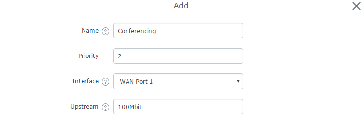
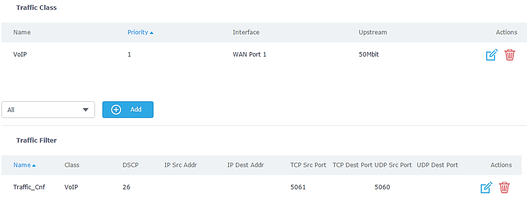
- On “Traffic Class”, click “Add” to create a traffic Class in order to set the priority, choose the WAN Interface set on previous step, and define the Upstream bandwidth value.
Note: Upstream bandwidth on each created class will be added together and should not surpass the Upstream bandwidth value set in QoS → Basic
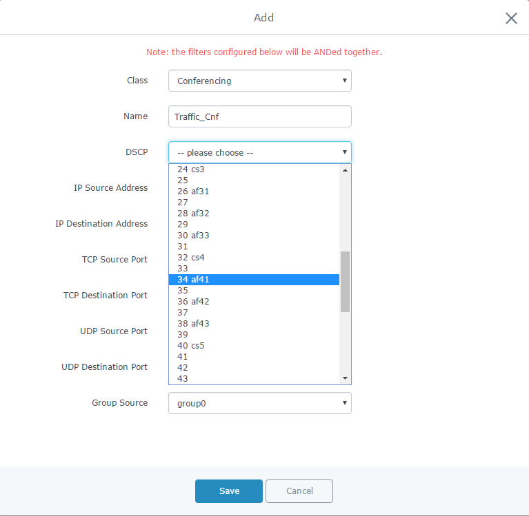
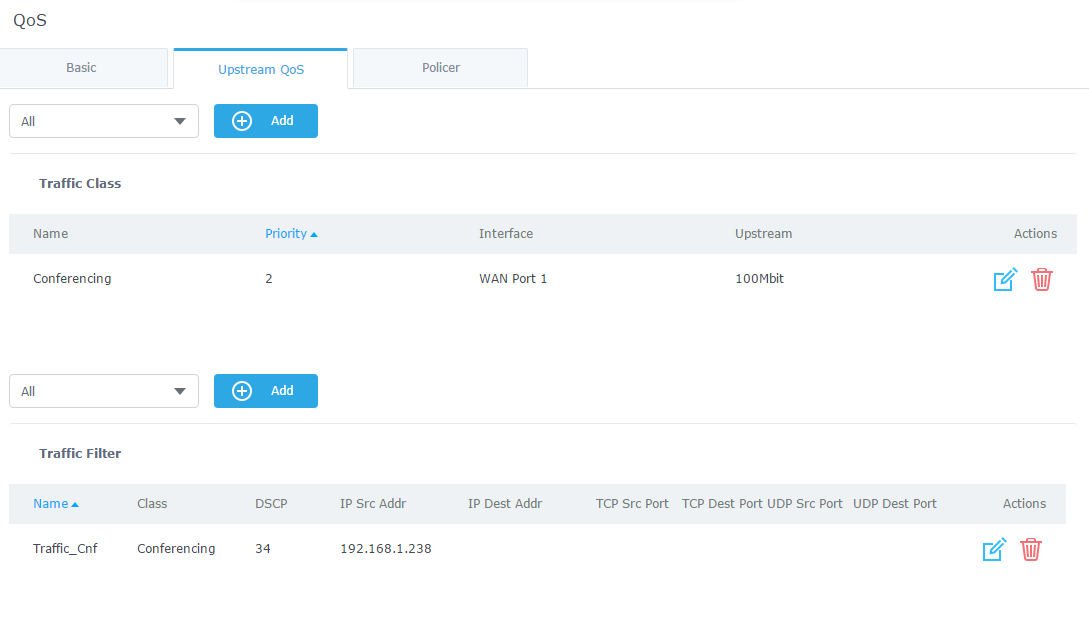
- After creating the traffic class, users will need to assign this class as Traffic Filter, hence on Traffic Filter section click on “Add” to create a new Traffic Filter.
- Choose the Class from drop-down menu on “Class” field, in our example, we used Conferencing.
- Set a Name for the Traffic Filter, and choose the DSCP value (for conferencing purpose, it is advised to use 34 af41).
- On “IP Source Address”, set the device’s IP address, in our example, the conferencing System has 192.168.1.238 as IP.
- Save, Apply, and reboot the GWN7000 to take effect.
QoS Configuration using Source Port
Instead of prioritizing a specific IP address on the Network, it is also possible to prioritize traffic from a certain source port.
In below steps we will prioritize all traffic using 5060 and 5061 ports on UDP and TCP, which are standard ports for SIP signaling, similar steps can be performed for any other ports depending on the service/protocol.
- Similar to prioritizing by IP address, it is needed to enable QoS from QoS → Global, and enable related WAN port.
- Create a class with a priority and upstream bandwidth value from QoS → Upstream
- Create a traffic filter in order to assign the class created in previous step.
- In our example will set 5061 in TCP source port and 5060 in UDP source port, and setting the DSCP value to “26 af31” which recommended for VoIP signaling, as shown in below figure.
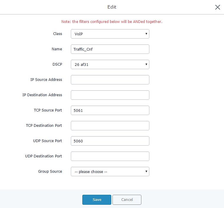
- Save, Apply, and reboot the GWN7000 to take effect.
QoS Configuration for a Network Group (using VLANs)
The GWN7000 offers the possibility to create different Network Groups separated by VLANs, this allows prioritizing the whole traffic on a certain network group using QoS.
This is useful in installation where data and voice for example are separated via VLANs through network groups.
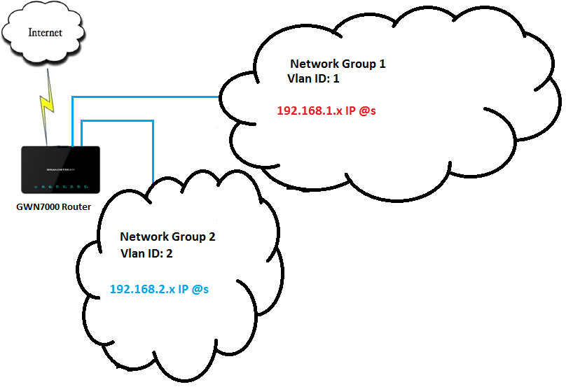
In above example figure we supposed that GWN7000 has two Network Groups.
We will prioritize all traffic coming from Network Group 2, please refer to below steps for above example, and note that similar steps can be applied for any other network group:
- Similar to prioritizing by IP address/Source Port, it is needed to enable QoS from QoS → Global, and enable related WAN port.
- Create a class with a priority and upstream bandwidth value from QoS → Upstream.
- Create a traffic filter in order to assign the class created in previous step.
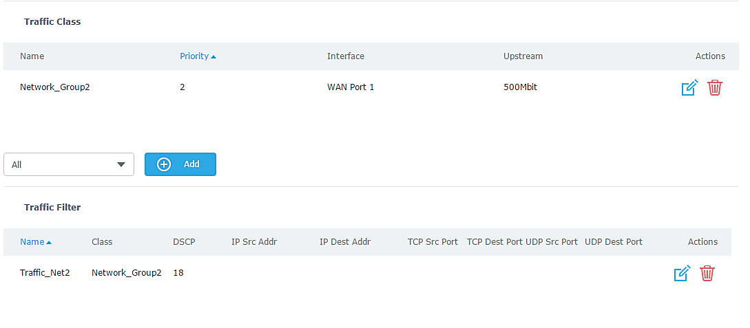
- In our example will set “DSCP” value to “26 af31” which recommended for Transactional data, and choose Network Group 2 on “Group Source”, as shown in below figure.
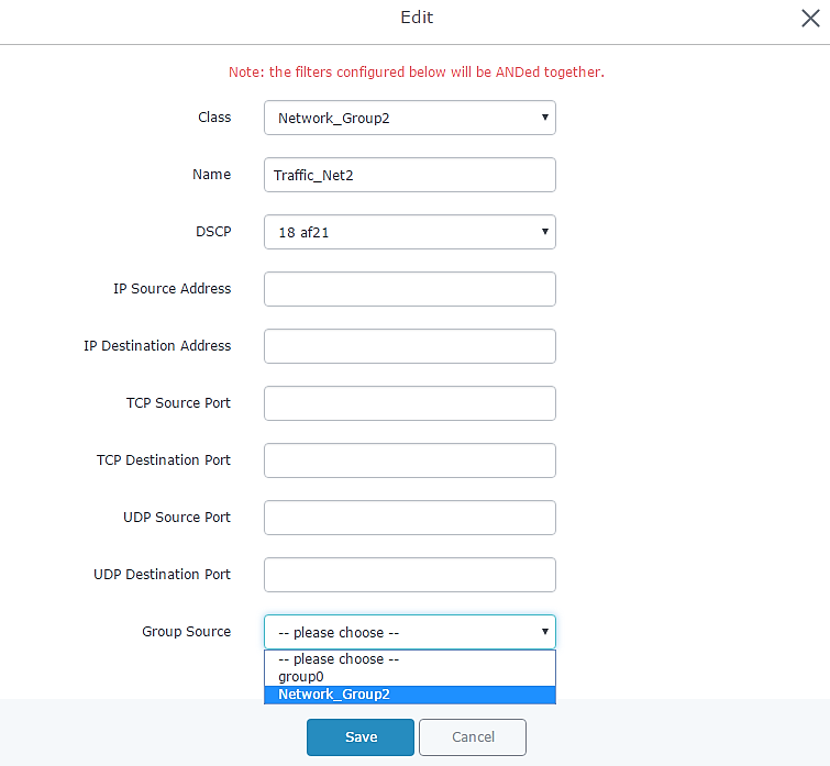
- Save, Apply, and reboot the GWN7000 to take effect.
SMART QUEUE
Feature Overview
Starting from firmware version 1.0.4.23, GWN7000 supports smart queue feature which adds an extremely effective QoS implementation which simple configuration steps. This will help to reduce BufferBloat and keeps latency at acceptable levels for delay sensitive applications such as voice over IP and video conferencing, even under high network load and congestion points.
Configuration
In order to configure and enable smart queue feature for QoS, user should navigate under the menu “Router→QoS→Smart Queue” which will show the status of each WAN link as shown on the following figure.
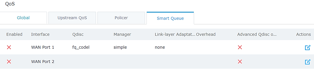
After this, users need to enable the option per WAN interface basis, click on ![]() button in order to enable and configure the feature on one of the WAN interfaces.
button in order to enable and configure the feature on one of the WAN interfaces.
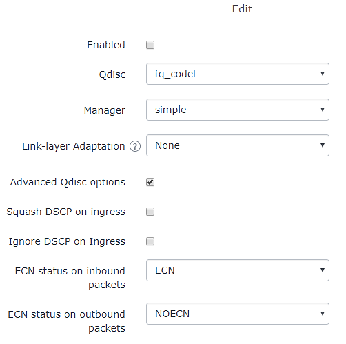
Figure 16: Smart Queue ConfigurationThe following table summarizes the available configuration parameters:
|
Option |
Description |
|
Enabled |
Check this option in order to enable the feature on the WAN interface. |
|
Qdisc |
Select which Queuing discipline method to use for QoS:
|
|
Manager |
Choose the type of the smart queue management: If fq_codel queuing discipline method is selected.
If cake queuing discipline method is selected.
|
|
Link -layer Adaptation |
Select the link-layer type for the WAN connection. This can be used to compensate for the link-layer overhead of certain types of WAN connections.
|
|
Overhead |
If the link-layer is set to something other than “none”, then the link-layer overhead setting can be used to specify how many bytes of overhead there are. Defaults are 8 for Ethernet, and 44 for ATM. |
|
Advanced Qdisc Options |
Check this option in order to show advanced Qdisc options to be used. |
|
Squash DSCP on ingress |
Select whether to squash or not the DSCP on ingress packets. By default, this option is disabled. |
|
Ignore DSCP on ingress |
Select whether to ignore DSCP on ingress packets or not. By default, this option is disabled. |
|
ECN Status on Inbound packets |
Select whether to set or not ECN status on inbound packets. |
|
ECN Status on outbound packets |
Select whether to set or not ECN status on outbound packets. |
Note:
It is not advised to configure an interface with smart queueing and filter based QoS queuing at the same time, and if it’s the case then the router will give preference to setting up the WAN interface in Smart Queue mode if both types of QoS are configured for the interface.
Sample Scenario
Let’s suppose that a user wants to activate Smart Queue QoS on his GWN7000 router which is connected to his cable modem via WAN1. The user has an internet connection speed of 100Mbps down and 10Mbps UP.
To have basic configuration, user should follow below steps:
- Go under Router→QoS and set the downstream to 100Mbit and Upstream to 10Mbit and enable QoS then save.
- Go under Router→QoS→Smart Queue and edit WAN1 interface.
- Enable Smart Queue on WAN1 and set the following options:
- Qdisc = fq_codel.
- Manager = Simple.
- Link-layer = none.
- Save and apply all changes, then reboot the router in order to take effect.
