Overview
This guide explains how to pair Grandstream PtP devices (supporting both PtP and PtMP modes) to create a wireless bridge between different sites.
The GWN7302 is a PtP/PtMP Fixed Wireless Bridge, functioning as a transparent Layer‑2 link, it extends the LAN across sites and passes DHCP, VLANs, and management traffic just like running an Ethernet cable between them.
- Use PtP mode when pairing one Master (Controller) with one Slave (Client).
- Use PtMP mode when one Master needs to connect to multiple Slave devices (up to 4 Slaves).
- The GWN7302 supports up to 5 km range in ideal line‑of‑sight conditions.
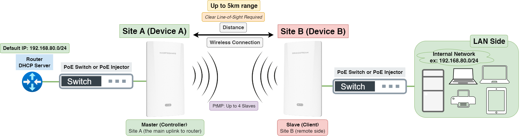
In this example illustration, we show a simple PtP link:
- Site A (Device A) is configured as the Master and connects to the main uplink (switch, router, or any network source).
- Site B (Device B) is configured as the Slave and extends the same network to the remote site.
Once paired, all devices at the remote site share the same LAN as the main site, with internet and network access as if directly connected to the main uplink.
Refer to the illustration below for a visual overview of the PtP wireless bridge setup:
Application Scenarios & Recommended Pairing Methods
This section outlines typical deployment scenarios for the GWN7302 and recommends the most suitable pairing approach for each one. Use it as a quick guide to decide which pairing procedure to follow.
Scene 1 – Simple point-to-point bridge
Both devices are still on the workbench or temporarily mounted, and you only need to build a single wireless bridge link between two sites. In this case, the fastest option is to use the hardware pairing buttons on the devices to create the link directly, without logging into any interface.
For detailed steps, see Pairing Using the RST/PAIR Button.
Scene 2 – One-to-many bridge (PtMP)
One device will act as the Master and connect to several remote sites, or you are adding additional bridge links to an existing deployment. The devices may already be installed or powered on in different locations. Here, it is recommended to use the Master device’s web interface to discover, configure, and pair all required Slave devices in a centralized way using either wired or wireless pairing method.
For detailed steps, see Method 2: Pairing Using the Web Interface.
Scene 3 – On-site deployment using the GWN app
The devices are distributed across the site, and running Ethernet cables to a PC is difficult or inconvenient. An installer primarily works with a smartphone or tablet. In this scenario, the installer can connect to the device’s management Wi-Fi and use the GWN app to complete configuration and pairing directly on site.
For detailed steps, see Method 3: Pairing Using the GWN App.
LED Indicators – Quick Reference
The LED indicators help you check device status, pairing progress, and link quality between devices. Use them during installation and alignment to ensure proper operation.
LED | Status | Meaning |
Sys (System) | Solid Yellow | Disconnected after pairing (Slave). |
Solid Pink | Device powered on & ready (factory default Slave mode or Pairing in progress). | |
Blinking Pink | Discovering the device and establishing a connection. | |
Rapidly Blinking Pink | Pairing confirmed (the RST/PAIR button was successfully pressed on the Slave device). | |
Solid Blue | Paired successfully, link established. | |
Solid Red | Pairing failed. | |
Blinking Blue | Configuration update in progress | |
Blinking green | Firmware update in progress | |
Solid green | The firmware update successful/rebooting | |
Blinking Red | Restore factory | |
Signal LEDs (3 bars) | 1–3 Green bars | Slave: Link quality between this device and the paired Master. 3 LEDs turn blinking green in cycle when waiting to be discovered by Master. |
Master: All 3 LEDs turn solid green when role is active. 3 LEDs turn blinking green in cycle when scanning Slaves. | ||
NET1 (PoE IN) | Solid/Flashing Green | Ethernet link or data activity (PoE input). |
NET2 (PoE OUT) | Solid/Flashing Green | Ethernet link or data activity (PoE output). |
LED Indicators
Tip: After pairing, use the 3 Signal LEDs to fine-tune antenna alignment between the two devices. Adjust both units until you see 3 solid Green bars for optimal performance.
Pairing Methods
Pairing Method 1: Pairing Using the RST/PAIR Button
This method applies to Scene 1 – Simple point-to-point bridge. For more details, refer to [Application Scenarios & Recommended Pairing Methods]
This method lets you pair two GWN7302 devices quickly using the physical RST/PAIR button, no Web UI or app needed.
Default Mode: This method creates a Point-to-Point (PtP) link (one Master, one Slave).
To pair multiple Slaves (Point-to-Multipoint / PtMP), use Method 2: Pairing Using the Web Interface
Step 1: Power and Reset
- Connect both devices to power using a PoE switch or PoE injector.
Important: ensure the devices are placed at least one meter apart from each other to prevent signal interference during the initial setup.
- (Optional) If the devices were used before, press and hold the RST/PAIR button for 7 seconds to perform a factory reset. (Note: This step is not required for new, out-of-the-box devices.)
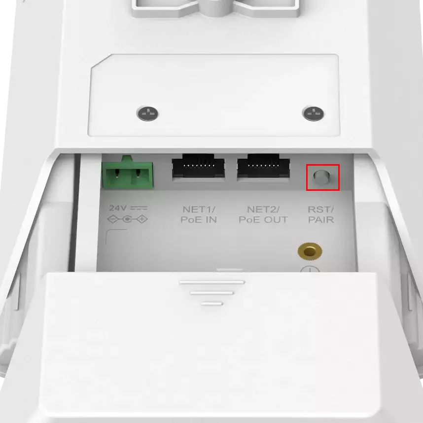
- When the SYS LED shows solid pink, the device is ready and in Slave mode.
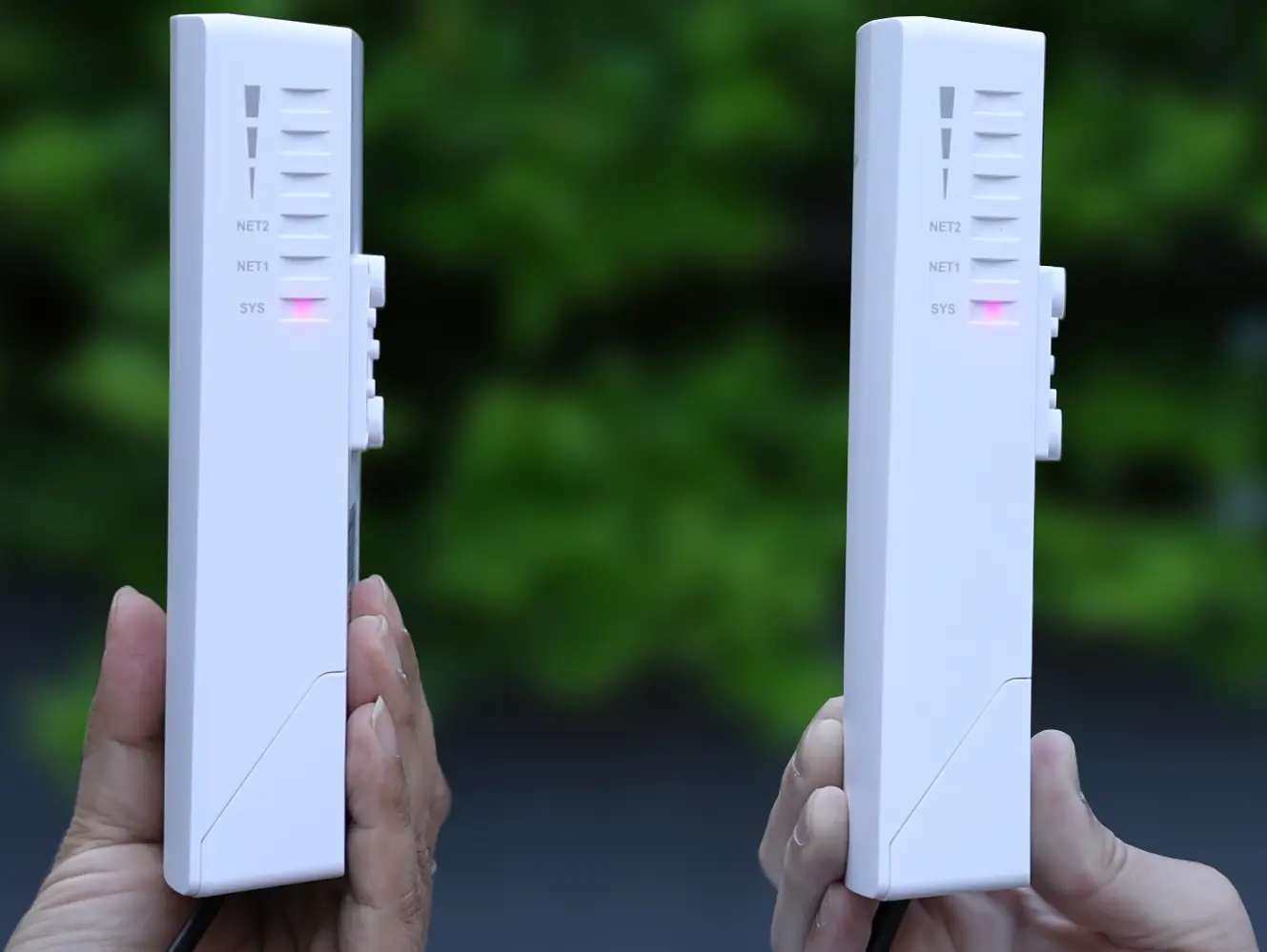
- Wait until the 3 Signal LEDs begin blinking green in a cycle. This indicates the reboot is complete and the device is ready for pairing.
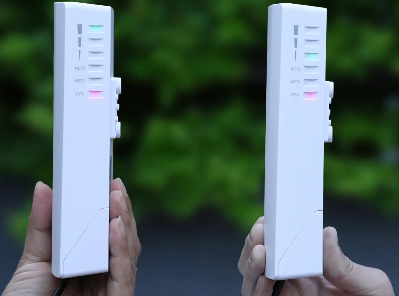
Step 2: Start Pairing on the Master (Device A)
- Choose the device you want to use as the Master.
- On that device, press the RST/PAIR button 3 times quickly to trigger scanning.
- The SYS LED will blink blue, then turn solid blue.
- The Signal LEDs will first turn solid green, then begin blinking green in a cycle. This means the Master is scanning for nearby Slaves.
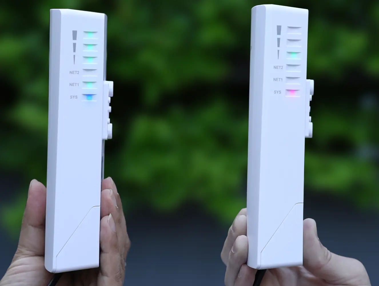
Step 3: Confirm on the Slave (Device B)
- The SYS LED begins blinking pink. Within 30 seconds, press the RST/PAIR button 1 time on the second device (the Slave). The SYS LED will rapidly blink pink to confirm a successful button press.
- The SYS LED will change to solid pink, showing that pairing is in progress.
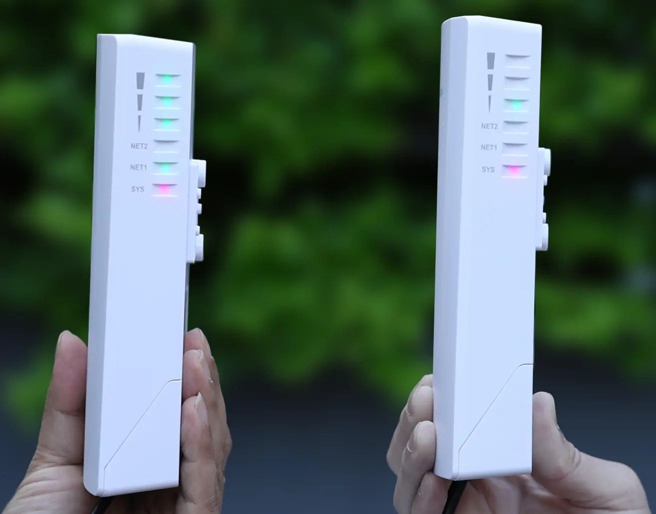
When pairing succeeds, both devices will go from blinking pink → solid pink → solid blue.
Once both SYS LEDs are solid blue, the wireless link is complete and active.
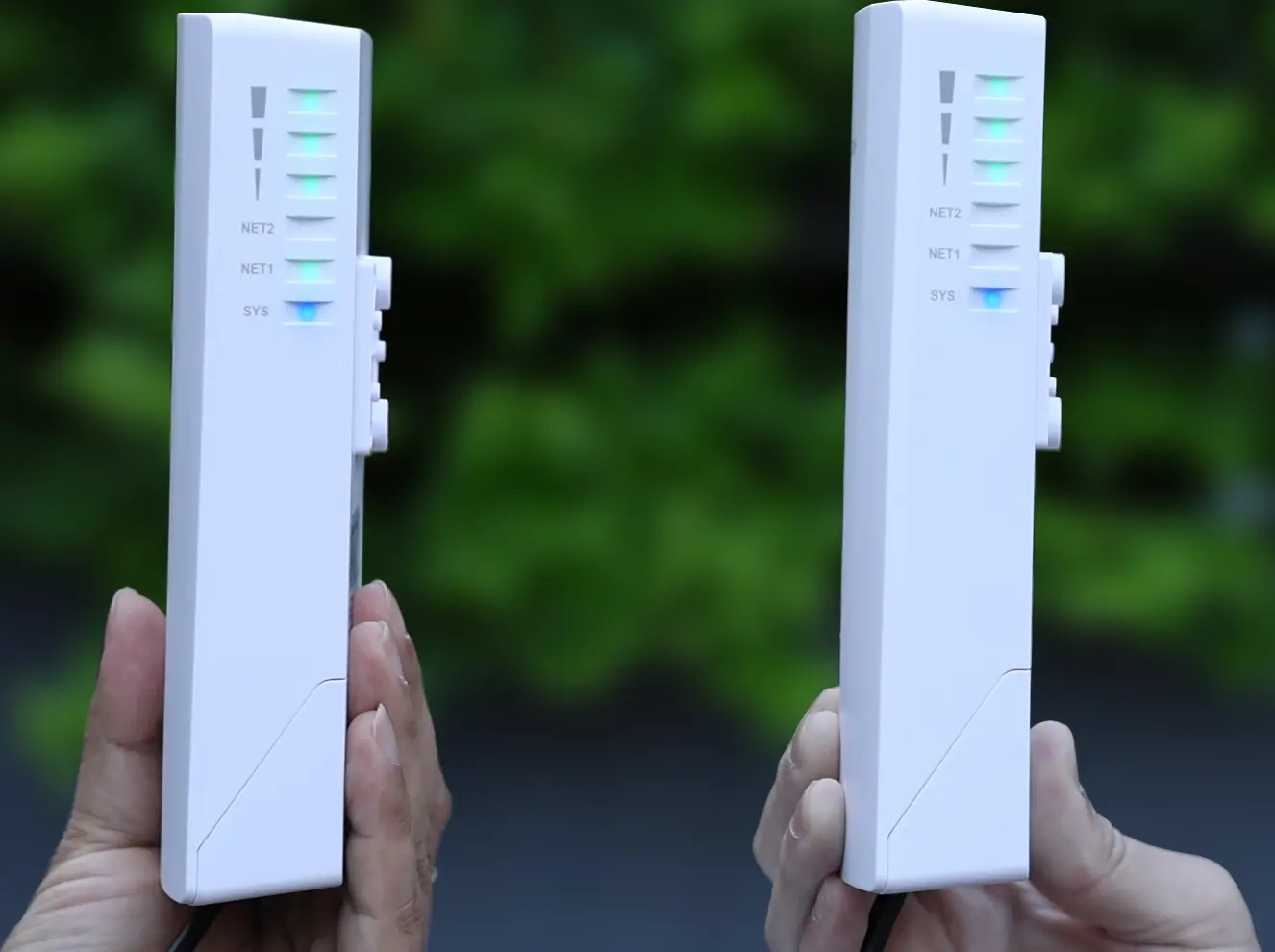
Note: If pairing fails (blinking red or nothing happens), you must go back to Step 1 and reset both devices before trying again.
Pairing Method 2: Pairing Using the Web Interface
This method applies to Scene 2 – One-to-many bridge (PtMP). For more details, refer to [Application Scenarios & Recommended Pairing Methods]
In this method, the device at Site A is configured as the Master, and all pairing management is handled through the Master Web UI. Slave devices simply need to be powered on, reset to factory defaults, and display a solid pink SYS LED. From there, they must either be connected to the same LAN (for wired pairing) or placed within wireless range (for wireless pairing).
Important: If you are pairing the devices wirelessly, they must be kept at a minimum distance of one meter from the Master. Because these devices use high-gain antennas designed for long-range links, placing them too close together can cause signal saturation and cause the pairing process to fail.
Step 1: Log In to the Master and Run Quick Setup
Connect your PC and the device to the same LAN. In your browser, access the device using:https://gwn_<mac>.local (Example: https://gwn_ec74d7a94318.local).
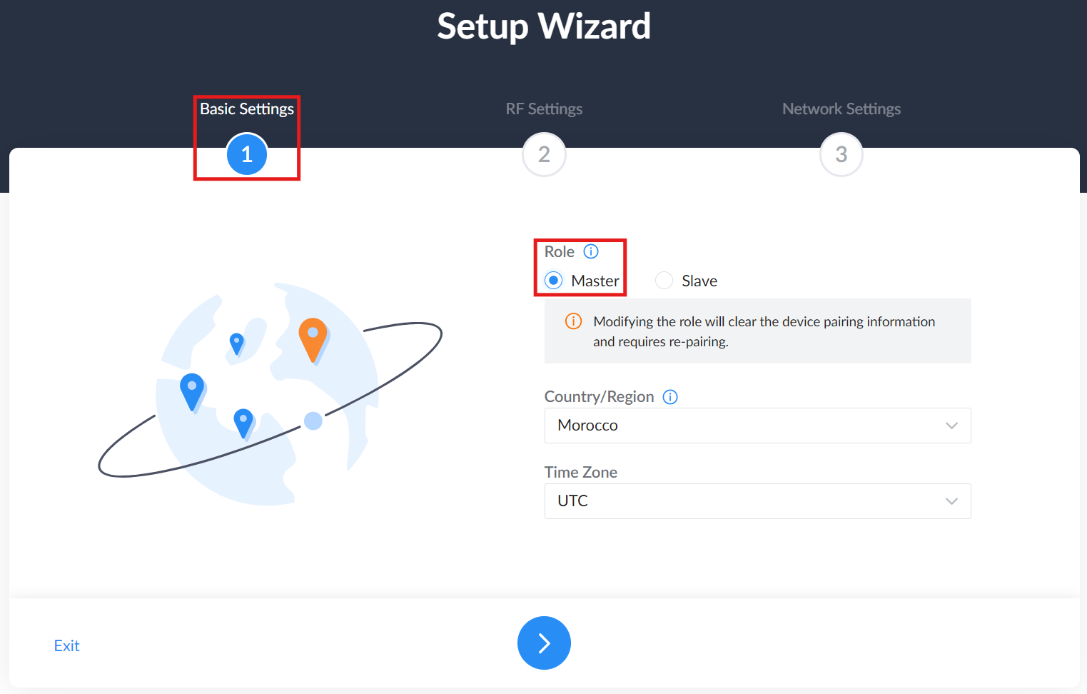
The Setup Wizard will launch automatically. Click Quick Setup to continue:
- Basic Settings: Set the Role to Master.
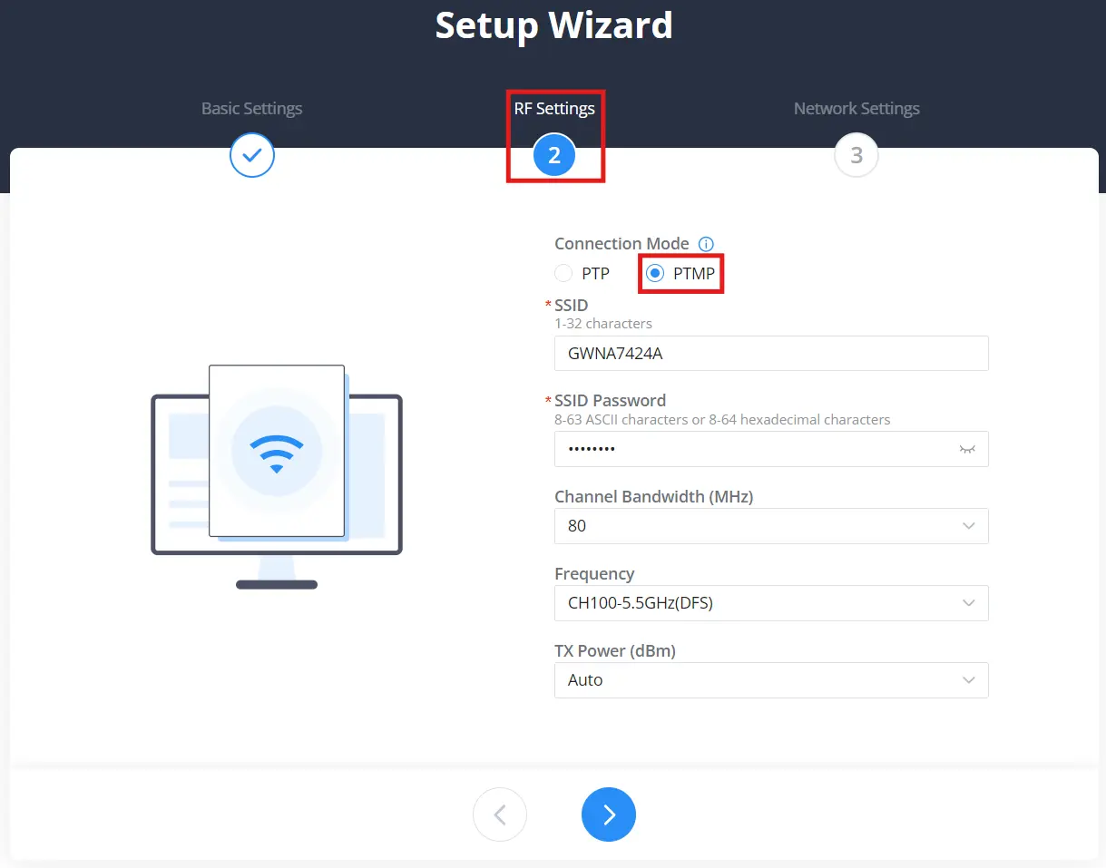
- RF Settings: Set Connection Mode to PTP (one-to-one) or PTMP (one-to-many), then configure the SSID and Password that the Master will broadcast and Slaves will use to connect.
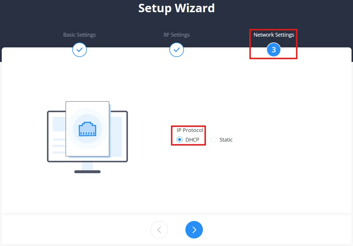
- Network Settings: Set IP Protocol to DHCP (auto IP from router). Use Static only if you want to assign a fixed IP manually.
Step 2: Add & Discover Slaves from the Master
On the Master device, go to the Device Pairing page.
Click Add to start adding a new device.

After clicking Add, the Device Pairing → Preparations page appears.
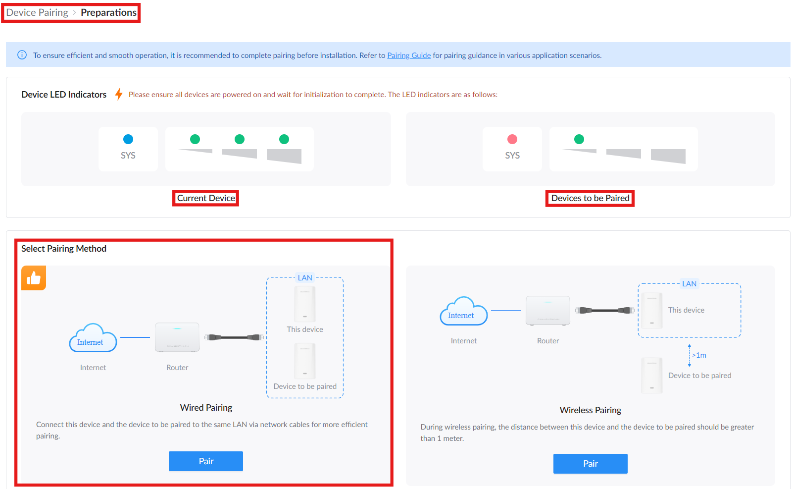
This page helps prepare both devices before discovery starts. Make sure all devices are powered on and wait for initialization to complete. Use the LED indicator reference to confirm the status of the Current Device and the Device to be paired.
Under Select the pairing method, choose one of the following:
- Wired Pairing: Connect this device and the device to be paired to the same LAN using network cables. This method is recommended for more efficient pairing.
- Wireless Pairing: Use this option when pairing wirelessly. Keep this device and the device to be paired more than 1 meter apart.
Click Go to Pair under the selected method to open the Add Paired Devices window.
After clicking Go to Pair, the Add Paired Devices window starts scanning for nearby Slave devices.
When devices are found, they appear in the Add Paired Devices window. The window includes two tabs: Pairable and Manageable.
If the list is still updating, wait for discovery to finish or click Rediscovery to scan again (only for wireless pairing).
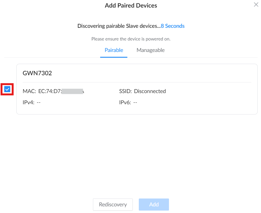
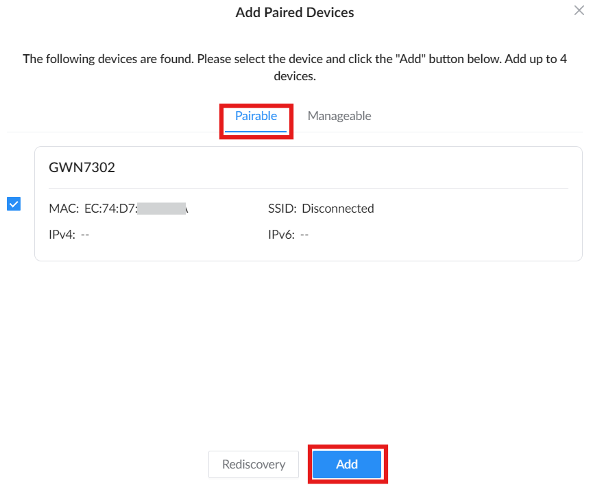
Option A: Pairing New or Factory-Reset Slaves (“Pairable” Tab)
Use the Pairable tab for a Slave device that is free, reset, or not already paired. Select the device checkbox, then click Add.
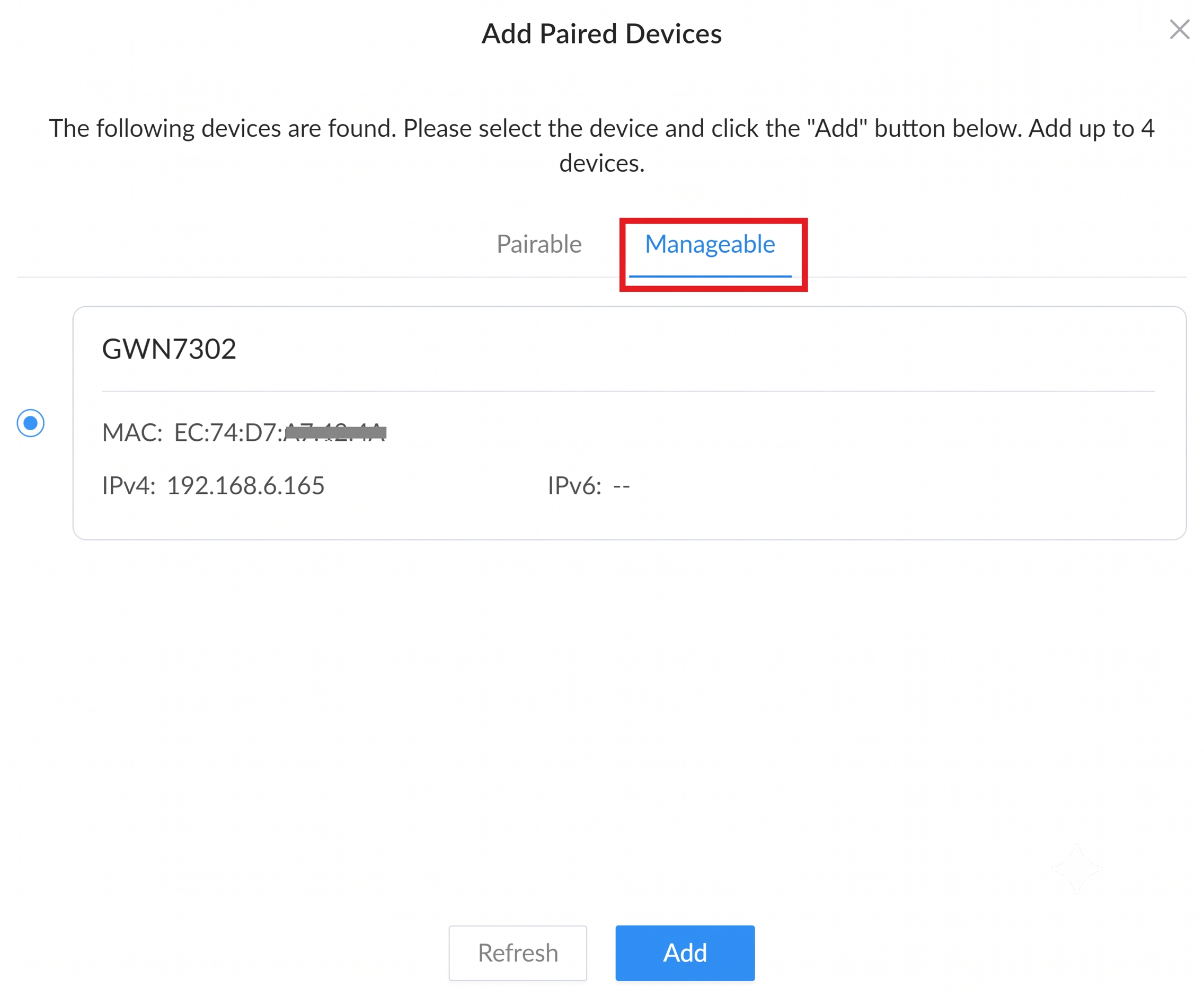
Option B: Migrating an Existing Slave (“Manageable” Tab)
Use the Manageable tab when the Slave device is already paired and needs to be added to this Master. Select the device, then click Add.
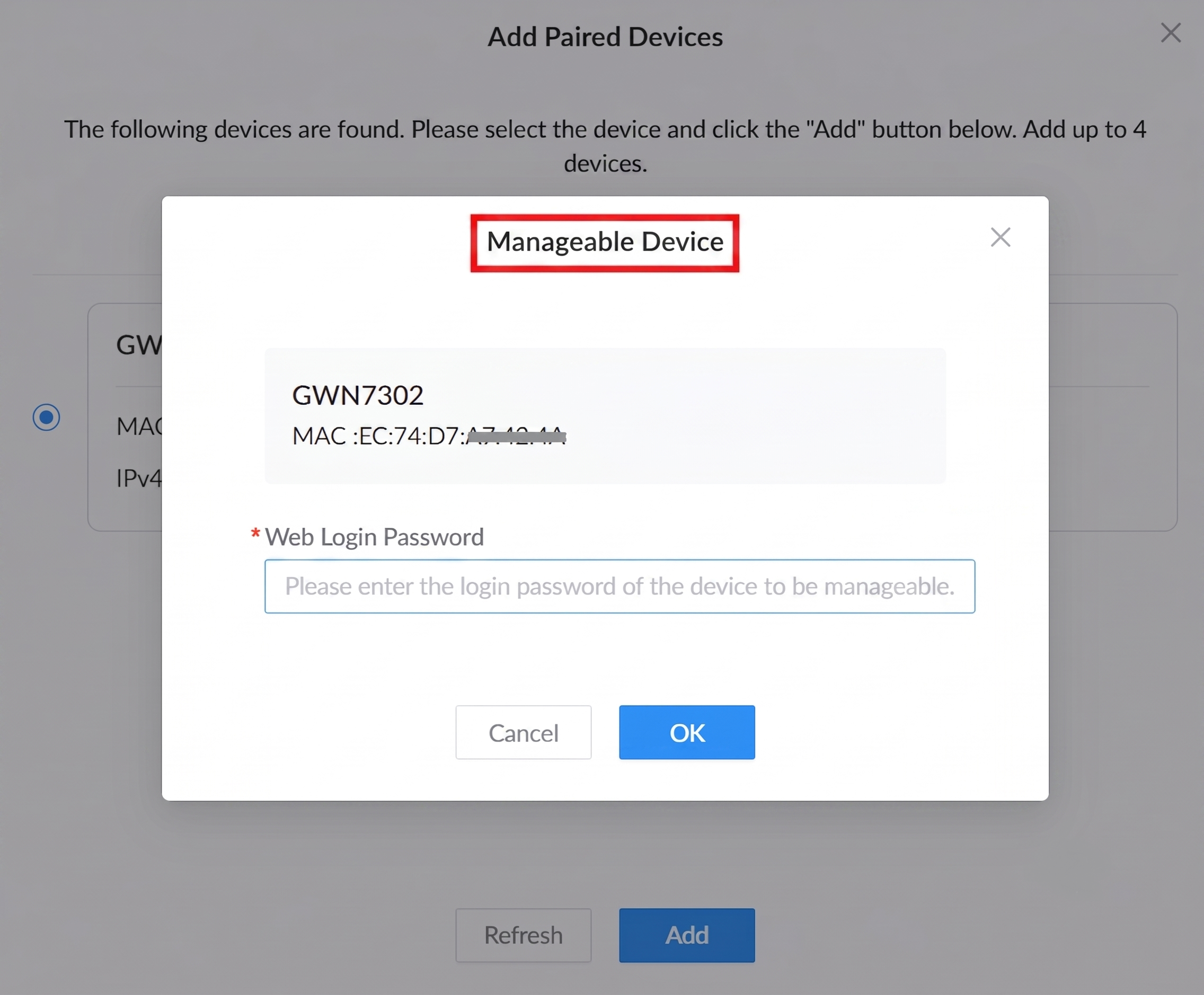
Note: Once the password is validated, this Master takes over the Slave successfully. You can skip Step 3 entirely for this device, as it will initialize and go online automatically.
In the Manageable Device window, enter the Slave device’s Web Login Password, then click OK to allow this Master to manage the selected Slave.
Step 3: Confirm & Complete Pairing
After clicking Add, the confirmation behavior depends on the selected pairing method.
For Wireless Pairing, the Add Paired Devices window starts a 30-second countdown and displays a message asking you to press the Slave device RST/PAIR button once within the countdown. Press the RST/PAIR button on the Slave device once to confirm pairing.
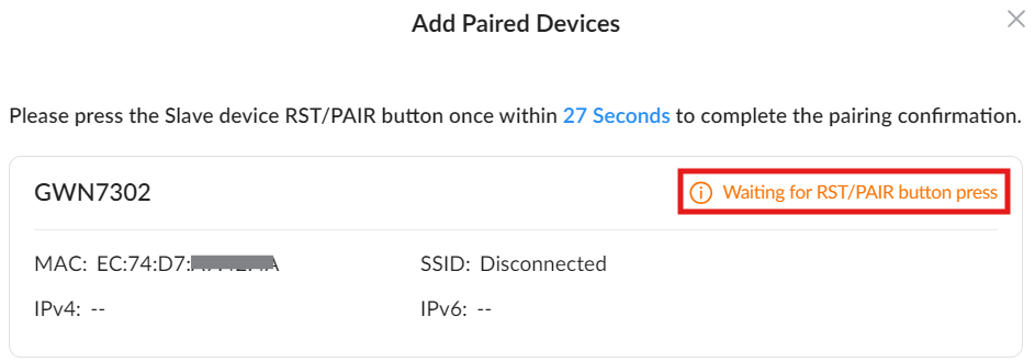
For Wired Pairing, no RST/PAIR button confirmation is required. After clicking Add, the device proceeds directly to pairing completion.
After pairing is completed, the device status changes to Paired successfully. The Slave may take a short time to initialize its configuration and go online.
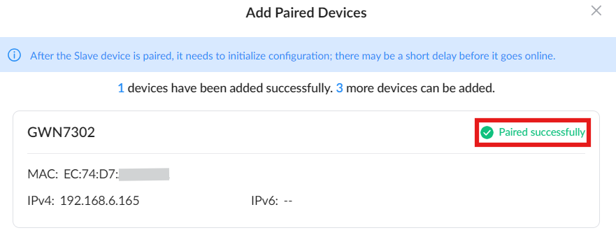
At this point, the wireless link between the Master and the Slave is active. To add more Slaves, repeat the same sequence: Add → discover → press the button on the Slave → check for “Paired successfully.”
If pairing fails, the status will show “Failed to pair”. In this case, reset the Slave again (hold RST/PAIR for 7 seconds), make sure it is powered on, within wireless range of the Master, and not already paired, then repeat the pairing process from Step 1.
If pressing the RST/PAIR button on the Slave is not possible (e.g., the device is mounted or hard to reach), you can log in to the Slave manually via its web UI.
Set the RF Settings (Role = Slave, Mode = PTP or PTMP, SSID & Password) to match the Master.
Once saved, the device will automatically pair when the Master performs Step 1 and Step 2. No need to execute Step 3.
Pairing Method 3: Pairing Using the GWN App
This method applies to Scene 3 – On-site deployment using the GWN app. For more details, refer to [Application Scenarios & Recommended Pairing Methods]
The GWN App offers a simple and intuitive way to pair and manage the GWN7302 device locally, without requiring a GDMS Networking account. This method is ideal for quick installations or setups in isolated environments. After downloading the app (via iOS or Android QR code), users can select the “Single Device” mode to begin. The app guides users through Wi-Fi-based device discovery or manual IP login, as needed. Helpful instructions are provided in case of connection issues, including tips to enable Management Wi-Fi or reset the device via the RST/PAIR button. Once connected, users can launch the Quick Configuration Wizard, set basic and RF parameters, and finally monitor wireless statistics such as throughput and rate. The app also provides a clear visualization of link status and antenna alignment between devices (Master and Slave), making the setup of PTP or PtMP links seamless and efficient.
In addition to the previous pairing methods, the GWN7302 can also be configured and paired using the GWN App in Single Device Mode, without requiring a GDMS Networking account. This method is especially useful when setting up locally via a mobile device.
Note: Only GWN730X models support standalone mode pairing via the GWN App.
Requirement: The GWN App must be installed on your phone. Use the QR code to download it.
Scan the QR code to download the app on your preferred mobile device.

Step 1: Connect to the Device
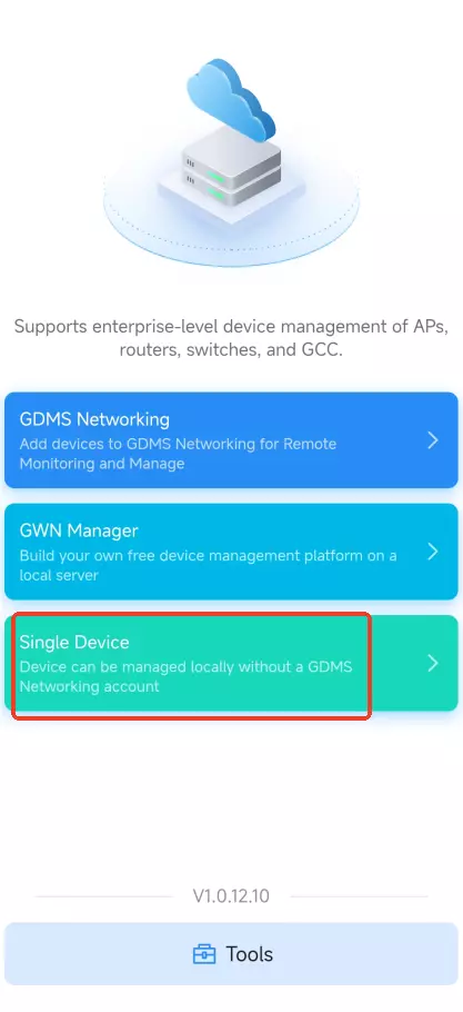
- Open the app and select Single Device from the main screen.
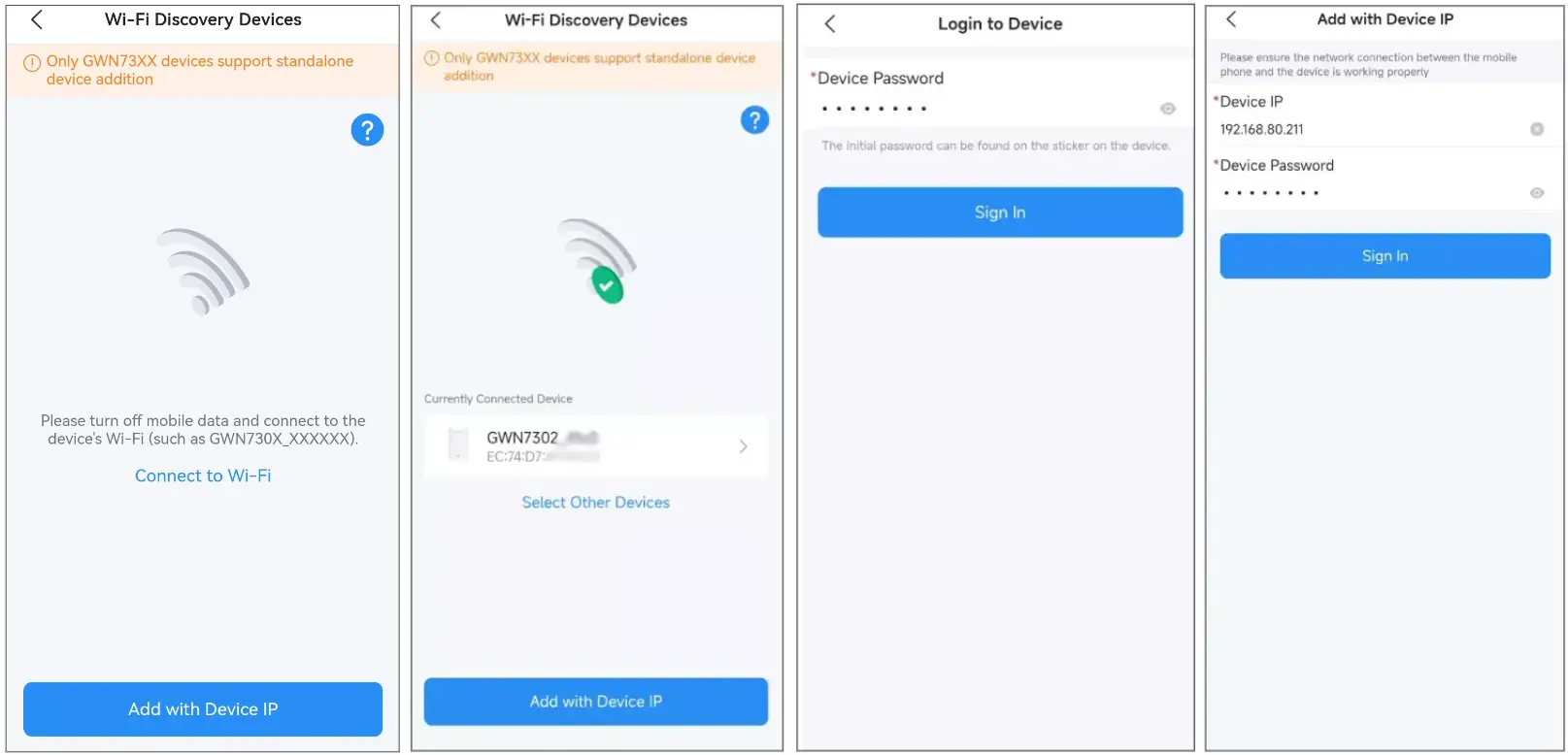
- Make sure the GWN7302 is powered on. It will broadcast a default SSID based on the device model and MAC address (e.g., GWN730X_XXXXXX), where the last six digits are from the device’s MAC address.
- Connect your phone to the Wi-Fi SSID broadcast by the device (format: GWN730X_XXXXXX, based on the model and MAC address). If connected, proceed. If not, tap Add with Device IP, enter the IP and password, ensure both phone and device are on the same network, then tap Sign In.
Step 2: Run the Setup Wizard
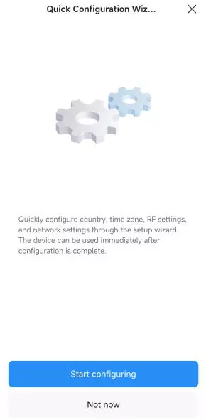
- Once logged in, tap Start Configuring to launch the wizard.
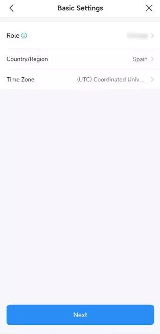
- In Basic Settings, choose the Role (Master or Slave), select Region, and set the Time Zone.
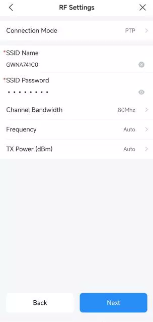
- In RF Settings, configure:
- Connection Mode: PtP or PtMP
- SSID and Password
- Bandwidth, Frequency, TX Power
Note: To pair additional devices, repeat the same steps. For the second unit (Slave), everything stays the same; just make sure to set the Role to Slave instead of Master during the setup.
Installation & Alignment Best Practices
Pair Locally First
Pairing the devices at close range before rooftop or pole installation is strongly recommended. This ensures the configuration is correct and the link is established before mounting.
Steps:
- Place both devices side by side (1–2 meters apart) indoors or in a temporary test setup.
- Power on both units and wait for the SYS LEDs to turn pink (ready state).
- Complete the pairing using either One-Key Button Pairing or Web UI Pairing, or the GWN App.
- Confirm the pairing sequence: SYS LEDs – Blinking Pink → Solid Pink → Solid Blue.
- Once paired successfully, you can proceed with outdoor installation.
Tip: Local pairing avoids alignment issues caused by distance, obstacles, or weather during outdoor setup.
Install & Align Antennas
Install at Final Locations
- Mount the devices securely on poles or walls using the provided brackets.
- Ensure a clear line-of-sight between both sites, avoiding trees, walls, or other obstructions.
- Tighten all screws and make sure both devices face directly toward each other.
Align Antennas
You can fine-tune the link quality using either method:
a) Using Device LEDs
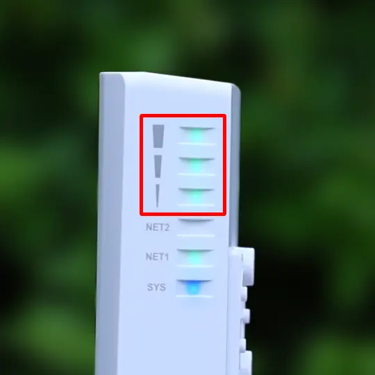
- Check the 3 Signal LEDs on the side of the unit.
- Rotate or tilt the device slowly until you reach 3 solid green bars for optimal signal.
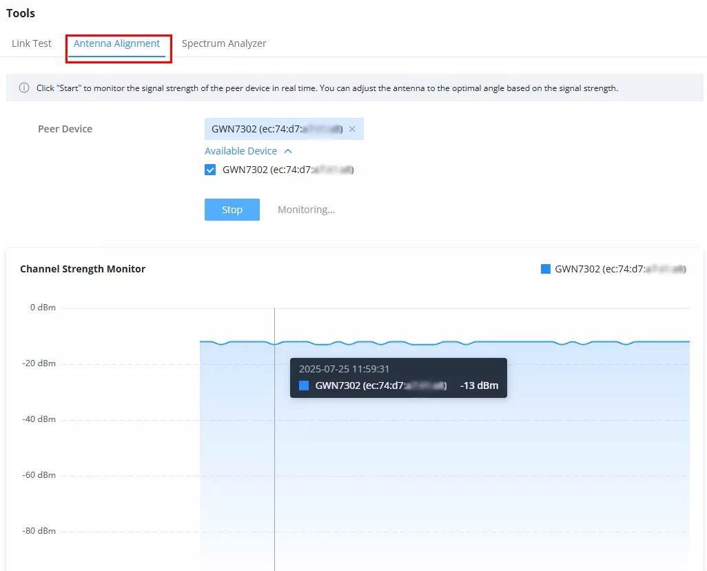
b) Using Web UI – Antenna Alignment Tool
- Go to Web UI → Tools → Antenna Alignment.
- Select the paired device from the list.
- Click Start to monitor real-time signal strength.
- Adjust the antenna angle until the graph shows the strongest (highest) dBm value.
(Optional) Verify Link Quality
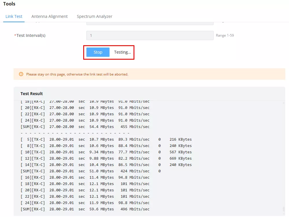
Link Test (iPerf)
The Link Test measures throughput between the two devices.
Who Does What?
- Either device can be Server or Client, but recommended:
- Master (Site A) → Server (easier to leave running).
- Slave (Site B) → Client (initiates the test).
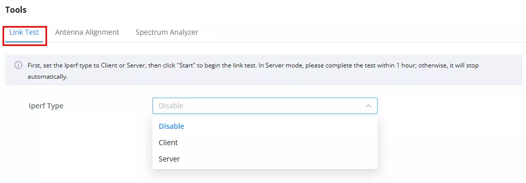
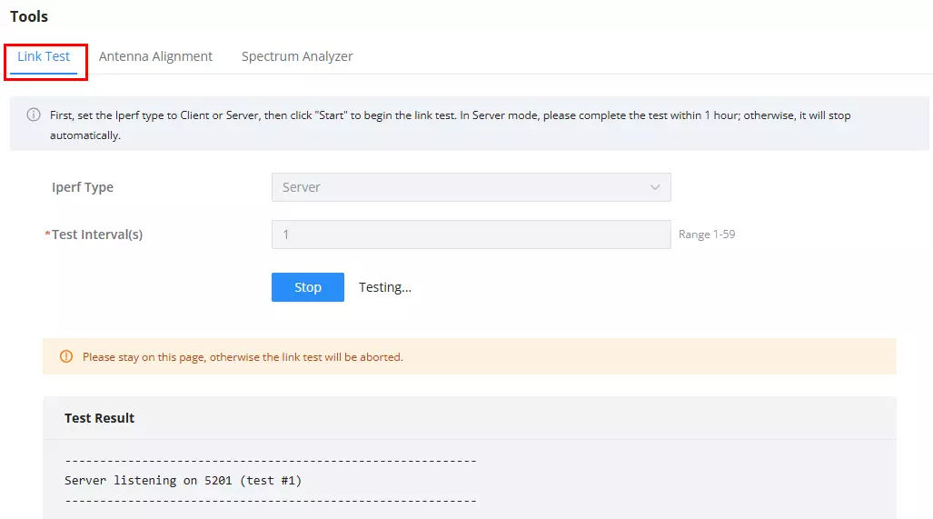
On Master (Server):
- Go to Web UI → Tools → Link Test.
- Select iPerf Type = Server and click Start.
- Leave it running (listening).
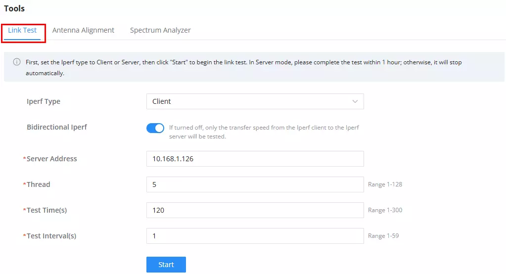
On Slave (Client):
- Go to Web UI → Tools → Link Test.
- Select iPerf Type = Client.
- Enter the Server’s IP address (auto-filled in most cases).
- (Optional) Enable Bidirectional iPerf to test both directions.
- Click Start to begin.
Review Results:
- Throughput and stability will appear under Test Result.
- Stop manually when finished.
Spectrum Analyzer (Optional RF Check)
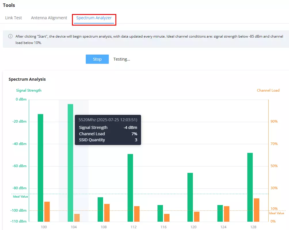
The Spectrum Analyzer scans the surrounding 5 GHz channels to detect interference.
When to Use?
- Before locking RF settings, or if link quality is poor.
How to Read?
- Signal Strength (Green Bars): Lower (closer to -85 dBm) = less interference.
- Channel Load (Orange Bars): Ideal below 10%.
- SSID Quantity: Fewer SSIDs = cleaner channel.
Steps:
- Go to Web UI → Tools → Spectrum Analyzer.
- Click Start and wait for the scan.
- Choose a channel with low interference for best performance.
TDMA (Time Division Multiple Access)
The GWN7302 supports TDMA (Time Division Multiple Access) technology.
Enabling TDMA is recommended in the following deployment scenarios to enhance wireless performance and link stability.
Scenario 1: Long-Distance Point-to-Point (PtP) Deployment
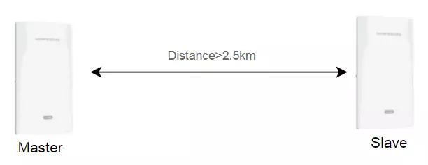
When the distance between Master and Slave exceeds 2.5 km, it is strongly recommended to enable TDMA. This improves connection stability, reduces retransmissions, and optimizes throughput in long-range links.
Scenario 2: Point-to-Multipoint (PtMP) Deployment
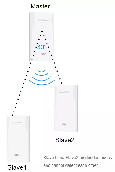
When operating in PtMP mode, Slave devices are not aware of each other and operate as hidden nodes.
Enabling TDMA in this scenario provides the following benefits:
- Better scheduling of wireless slots
- Improved throughput and capacity
- Reduced latency and jitter
- Minimized hidden node interference