Introduction
One of the major components of a wireless Access Point is the antenna. These radio components come in different shapes and sizes to fit specific deployment needs, and each access point can bundle multiple antennas for sending and receiving signals in order to benefit from the MIMO (Multiple Input/Multiple Output) technology and obtain higher throughput and signal resilience, also the arrangement of multiple antennas internally to a single WLAN access point can be used to influence the shape and behavior of the wireless signal (both on transmit and receive). To better understand how each GWN access point model broadcasts the wireless signals, this paper provides radiation patterns to help engineers during the deployment process.
The GWN7661E is an in-wall AX3000 Wi-Fi 6 access point designed for offices, hotels, homes, apartments, and similar deployments. It supports 2×2:2 MU-MIMO at 2.4 GHz and 3×3:2 MU-MIMO at 5 GHz, with two dual-band internal antennas and one additional 5 GHz internal antenna. It provides three Gigabit Ethernet ports for connected devices and one Gigabit uplink port with PoE/PoE+ support.
We begin this report with a glossary of basic definitions related to antennas’ radio characteristics and then progress through the specific radiation patterns for the GWN7661E access point series.
Terminology
In this first part, we will provide a quick brief review of some fundamental concepts related to antennas and radio propagation:
Antenna: An antenna is a transducer between a feed signal and radiated wave over the space, it is usually attached to a transmitter/receiver unit and the radiated energy is characterized by the antenna’s radiation pattern.
Antenna pattern: The radiation pattern or antenna pattern is the graphical representation of the radiation properties of the antenna and how it radiates energy out into space or how it receives energy (reciprocity). An antenna radiates energy in all directions, at least to some extent, so the antenna pattern is actually three-dimensional. It is common, however, to describe this 3D pattern with planar patterns called the principal plane patterns. These principal plane plots are commonly referred to as antenna radiation patterns.
Isotropic radiator: An isotropic radiator is a hypothetical lossless antenna that radiates its energy equally in all directions. This imaginary antenna would have a spherical radiation pattern and the principal plane cuts would both be circles since any plane cut through a sphere would be a circle.
Gain: The gain of an antenna (in a given direction) is defined as the ratio of the power gain in that direction to the power gain of a reference antenna in the same direction, usually an isotropic radiator is set as reference and the value of the gain is expressed in dBi. It is important to state that an antenna with gain doesn’t generate power and it does simply direct the way the radiated power is distributed relative to radiating the power equally in all directions, thus the gain is just a characterization of the way the power is radiated.
Efficiency: The efficiency of an antenna is the ratio of the power radiated by the antenna to the power accepted at its input. A high-efficiency antenna has most of the power present at the antenna’s input radiated away. A low-efficiency antenna has most of the power absorbed as losses within the antenna or reflected away due to impedance mismatch which causes an antenna to not have an efficiency of 100%.
Antenna efficiency losses are typically due to:
- Conduction losses (due to finite conductivity of the metal that forms the antenna).
- Dielectric losses (due to the conductivity of a dielectric material near an antenna).
- Impedance mismatch loss.
Test environment
This report presents the antenna radiation patterns and measured gain and efficiency of the GWN7661E at 2.4 GHz and 5 GHz to help engineers during deployment planning.
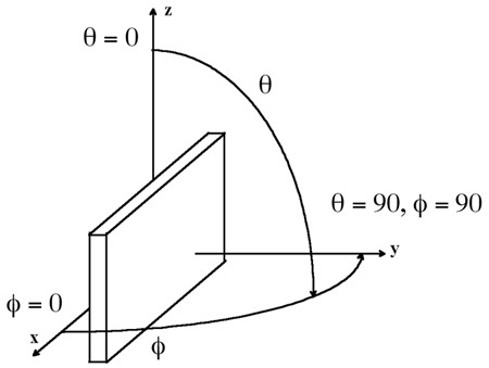
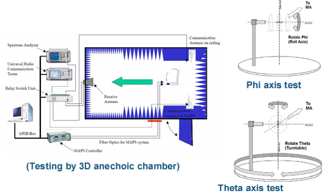
Antenna radiation patterns are typically measured in an anechoic environment to limit reflections. In an installed environment, obstacles, building materials, and surrounding structures affect signal propagation, so coverage varies between deployments.
The figure below illustrates an antenna test environment:
GWN7661E Antenna Characteristics
Reading the Antenna Patterns
Each two-dimensional plot shows how radiation varies with angle. The colored curves represent the frequencies listed in the plot legend. Gain is expressed in dBi, relative to an isotropic radiator, and efficiency is expressed as a percentage. Select an image to open it at full size.
The measurement tables retain the antenna identifiers from the test report. Gain and efficiency values are rounded to two decimal places. The listed frequencies are test points, not a statement of channel availability in every region.
2.4 GHz Antenna Radiation Patterns
| Antenna | XZ φ = 0° | YZ φ = 90° | XY θ = 90° |
|---|---|---|---|
| ANT1 | 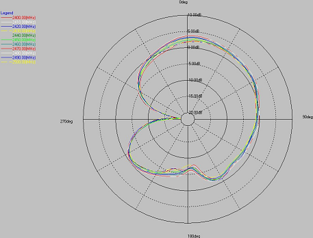 | 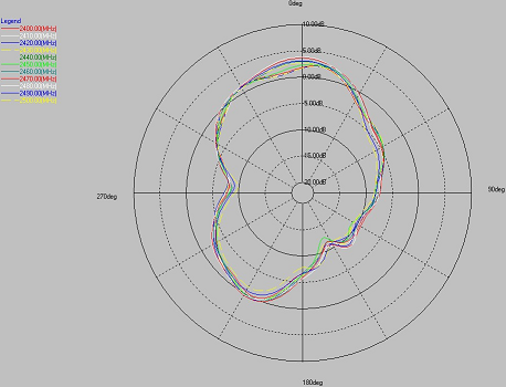 | 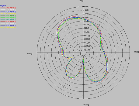 |
| ANT2 | 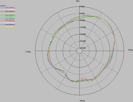 | 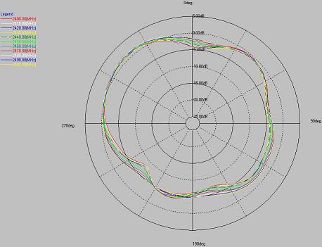 | 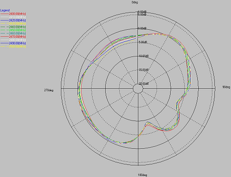 |
2.4 GHz Gain and Efficiency
| Frequency (MHz) | ANT1 | ANT2 | ||
|---|---|---|---|---|
| Gain (dBi) | Efficiency (%) | Gain (dBi) | Efficiency (%) | |
| 2400 | 2.30 | 55.93 | 2.36 | 60.03 |
| 2410 | 2.30 | 56.95 | 2.33 | 60.16 |
| 2420 | 2.37 | 57.81 | 2.47 | 61.08 |
| 2430 | 2.32 | 55.16 | 2.43 | 58.85 |
| 2440 | 2.39 | 55.01 | 2.53 | 58.90 |
| 2450 | 2.59 | 55.49 | 2.69 | 61.30 |
| 2460 | 3.05 | 60.41 | 2.74 | 63.53 |
| 2470 | 3.66 | 66.39 | 2.86 | 66.21 |
| 2480 | 3.85 | 67.26 | 2.72 | 65.16 |
| 2490 | 3.10 | 58.66 | 2.49 | 62.23 |
| 2500 | 2.66 | 54.04 | 2.43 | 61.56 |
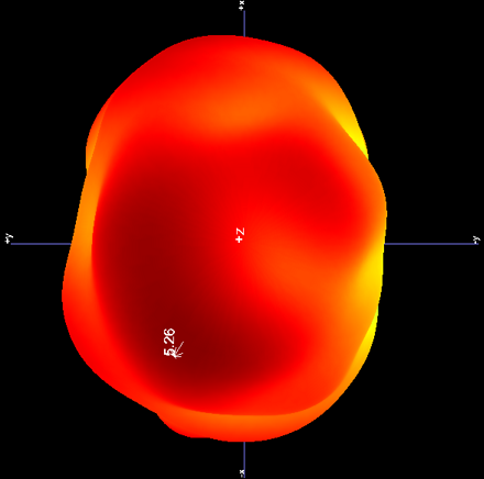
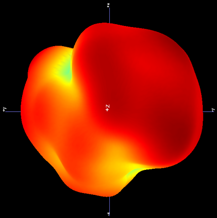
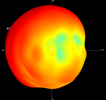
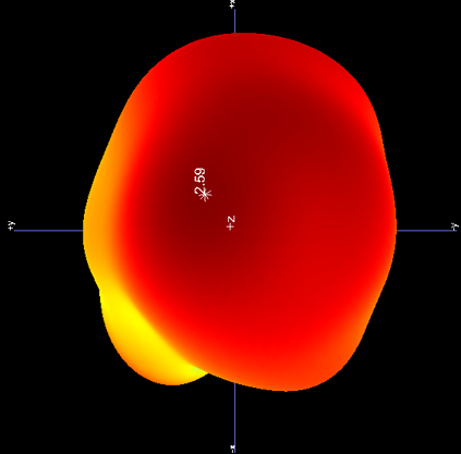
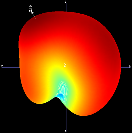
2.4 GHz 3D Radiation Patterns
5 GHz Antenna Radiation Patterns
| Antenna | XZ φ = 0° | YZ φ = 90° | XY θ = 90° |
|---|---|---|---|
| ANT1 | 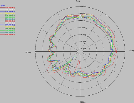 | 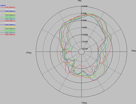 | 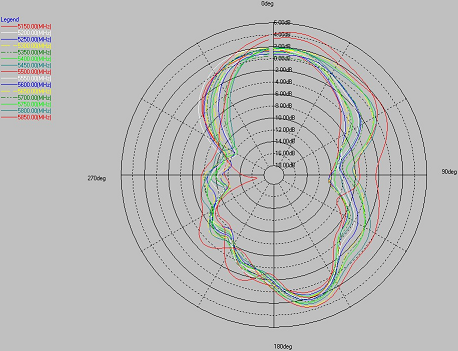 |
| ANT2 | 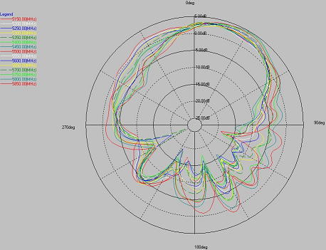 | 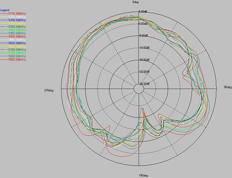 | 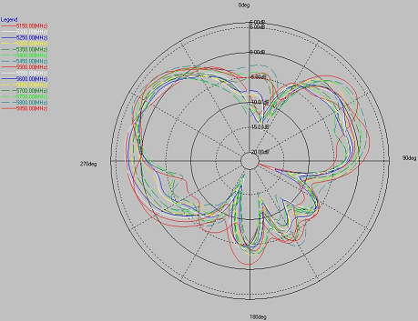 |
| 5G1 | 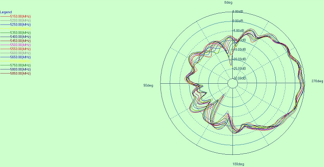 | 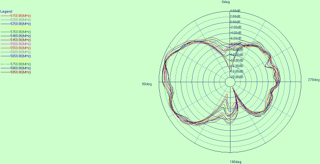 | 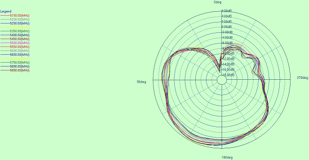 |
5 GHz Gain and Efficiency
| Frequency (MHz) | ANT1 | ANT2 | 5G1 | |||
|---|---|---|---|---|---|---|
| Gain (dBi) | Efficiency (%) | Gain (dBi) | Efficiency (%) | Gain (dBi) | Efficiency (%) | |
| 5150 | 5.58 | 76.48 | 4.23 | 71.93 | 5.13 | 74.19 |
| 5200 | 5.60 | 78.95 | 4.28 | 69.46 | 5.24 | 73.40 |
| 5250 | 5.07 | 71.28 | 4.02 | 65.08 | 5.33 | 75.07 |
| 5300 | 5.17 | 74.47 | 3.93 | 67.45 | 5.37 | 75.00 |
| 5350 | 5.21 | 74.25 | 3.86 | 66.90 | 5.29 | 74.03 |
| 5400 | 4.33 | 64.09 | 3.27 | 58.04 | 5.14 | 71.97 |
| 5450 | 4.38 | 68.20 | 3.57 | 59.90 | 4.85 | 65.02 |
| 5500 | 5.26 | 86.59 | 4.35 | 79.97 | 4.57 | 65.41 |
| 5550 | 4.40 | 65.89 | 3.64 | 58.84 | 4.63 | 68.43 |
| 5600 | 4.35 | 64.19 | 3.60 | 59.30 | 4.42 | 64.30 |
| 5650 | 4.43 | 74.11 | 3.92 | 63.14 | 4.23 | 62.63 |
| 5700 | 4.24 | 67.26 | 3.89 | 61.74 | 3.86 | 58.59 |
| 5750 | 5.85 | 85.07 | 4.66 | 69.60 | 3.84 | 58.97 |
| 5800 | 5.45 | 80.40 | 5.22 | 78.41 | 4.06 | 63.35 |
| 5850 | 5.47 | 84.30 | 5.01 | 79.67 | 4.33 | 68.52 |
5 GHz 3D Radiation Patterns