


Introduction
One of the major components of a wireless Access Point is the antenna. These radio components come in different shapes and sizes to fit specific deployment needs, and each access point can bundle multiple antennas for sending and receiving signals in order to benefit from the MIMO (Multiple Input/Multiple Output) technology and obtain higher throughput and signal resilience, also the arrangement of multiple antennas internally to a single WLAN access point can be used to influence the shape and behavior of the wireless signal (both on transmit and receive). To better understand how each GWN access point model broadcasts the wireless signals, this paper provides radiation patterns to help engineers during the deployment process.
The GWN7670LR is a long-range Wi-Fi 7 access point, ideal for medium-to-large businesses that need to provide long-range coverage. It offers IP66-level weatherproof capability, dual-band 2×2:2 MIMO with DL/UL OFDMA technology, and a sophisticated antenna design for maximum network throughput and expanded Wi-Fi coverage range. It supports flexible switching between internal directional antennas and external omnidirectional antennas. It can be combined with a directional antenna and PTMP technology (pending) to serve as a professional long-range wireless bridge. With 4096 QAM modulation, Wi-Fi 7 achieves a significant increase in data transfer rates. MLO technology optimizes spectrum resource utilization to ensure a smooth experience for every user.
To ensure easy installation and management, the GWN7670LR uses a controller-less distributed network management design in which the controller is embedded within the product’s Web User Interface. The GWN7670LR is also supported by GDMS Networking and GWN Manager, Grandstream’s cloud and on-premise Wi-Fi management platform. It is the ideal Wi-Fi AP for voice-over-Wi-Fi deployments and offers a seamless connection with Grandstream’s Wi-Fi-capable IP phones. With support for advanced QoS, low-latency real-time applications, mesh networks, captive portals, BLE 5.3, 256 concurrent clients per AP, 1×2.5 Gigabit network port with PoE+, and 1x 2.5 Gigabit SFP port. GWN7670LR is an ideal long-range Wi-Fi access point for enterprises, multiple-floor offices, warehouses, parks, hospitals, schools, and more.
Terminology
In this first part, we will provide a quick review of some fundamental concepts related to antennas and radio propagation:
Antenna: An antenna is a transducer between a feed signal and a radiated wave over space; it is usually attached to a transmitter/receiver unit, and the radiated energy is characterized by the antenna’s radiation pattern.
Antenna pattern: The radiation pattern or antenna pattern is the graphical representation of the radiation properties of the antenna and how it radiates energy out into space or how it receives energy (reciprocity). An antenna radiates energy in all directions, at least to some extent, so the antenna pattern is actually three-dimensional. It is common, however, to describe this 3D pattern with planar patterns called the principal plane patterns. These principal plane plots are commonly referred to as antenna radiation patterns.
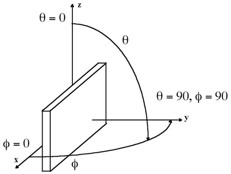
Isotropic radiator: An isotropic radiator is a hypothetical lossless antenna that radiates its energy equally in all directions. This imaginary antenna would have a spherical radiation pattern and the principal plane cuts would both be circles since any plane cut through a sphere would be a circle.
Gain: The gain of an antenna (in a given direction) is defined as the ratio of the power gain in that direction to the power gain of a reference antenna in the same direction; usually an isotropic radiator is set as reference, and the value of the gain is expressed in dBi. It is important to state that an antenna with gain doesn’t generate power and it does simply directs the way the radiated power is distributed relative to radiating the power equally in all directions; thus the gain is just a characterization of the way the power is radiated.
Efficiency: The efficiency of an antenna is the ratio of the power delivered to the antenna relative to the power radiated from the antenna. A high-efficiency antenna has most of the power present at the antenna’s input radiated away. A low-efficiency antenna has most of the power absorbed as losses within the antenna or reflected away due to impedance mismatch, which causes an antenna to not have an efficiency of 100%.
Antenna efficiency losses are typically due to:
- Conduction losses (due to finite conductivity of the metal that forms the antenna).
- Dielectric losses (due to the conductivity of a dielectric material near an antenna).
- Impedance mismatch loss.
Test Environment
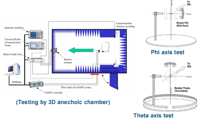
This test report gives schematic diagrams with antenna distribution of the GWN7670LR access point, along with the antenna radiation patterns of 2.4Ghz and 5Ghz frequencies in order to help engineers during the deployment process.
Please note that these radiation patterns are gathered in a fully anechoic environment. Their shape will change in installed environments depending on the obstacles that the wireless signal might face. Every deployment will behave differently due to materials, geometries of structures, etc, and how these materials behave at 2.4GHz, 5GHz, and 6GHz.
The figure below gives an overview of the test environment used:
GWN7670LR Antenna Characteristics
Antenna Patterns
This section presents the antenna radiation patterns of the GWN7670LR access point based on conducted testing. The plots are shown in the XZ and YZ planes, which correspond to the vertical (elevation) views, and in the XY plane, which corresponds to the horizontal (azimuth) view.
- GWN7670LR Antenna Radiation Patterns (2.4 GHz / 5GHz)
Label | 2.4GHz | 5GHz |
E Side | 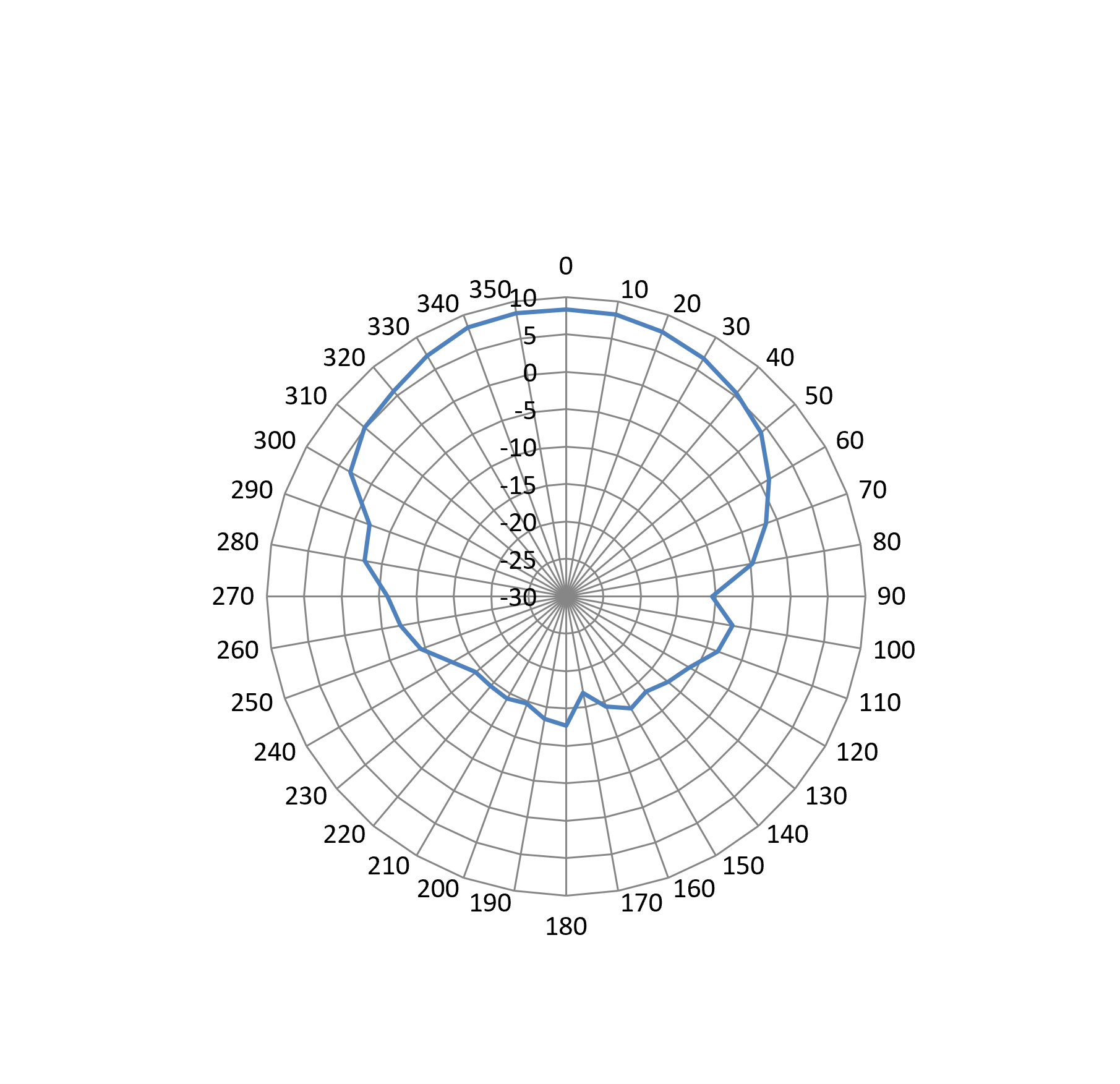 | 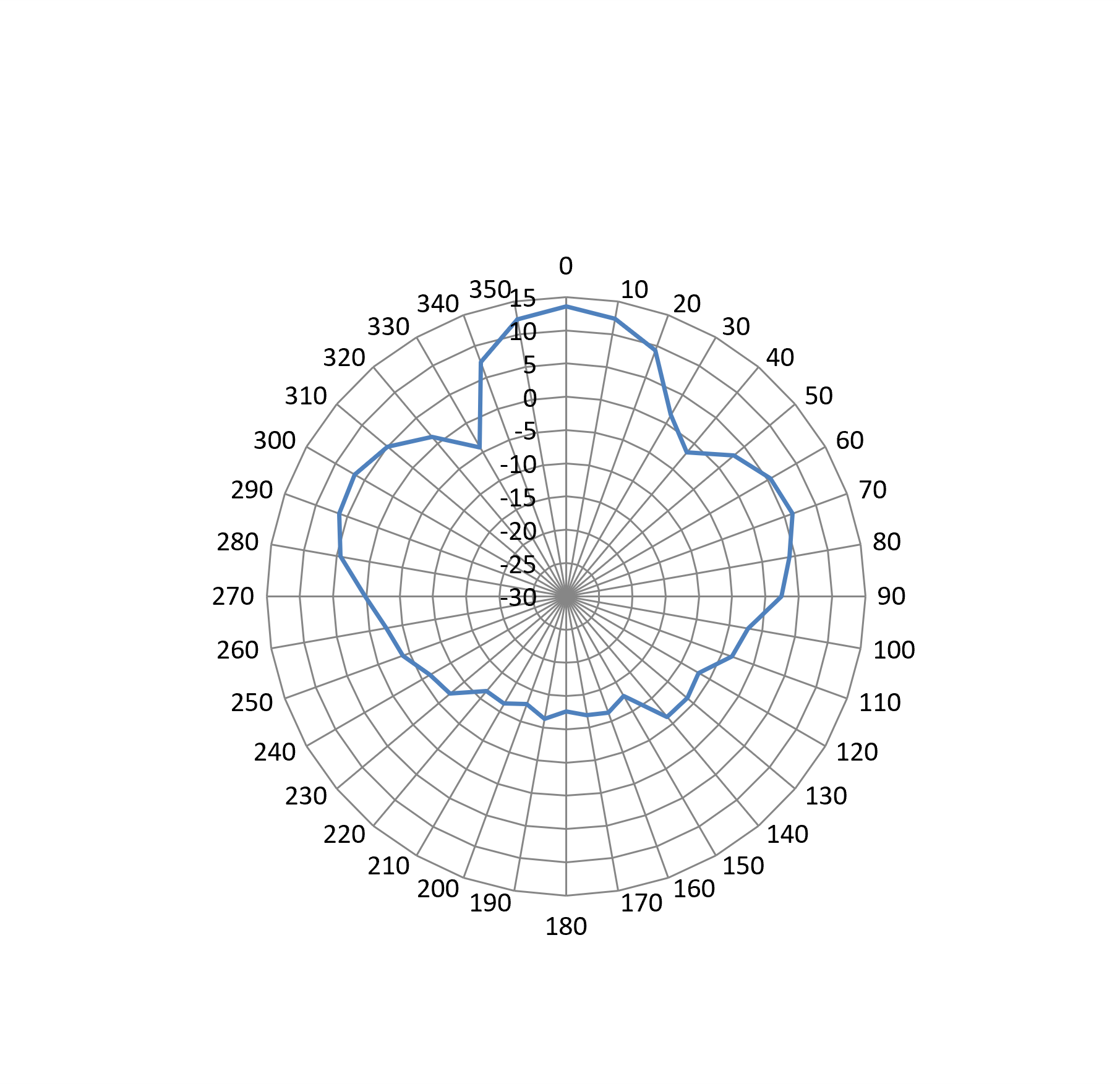 |
H Side | 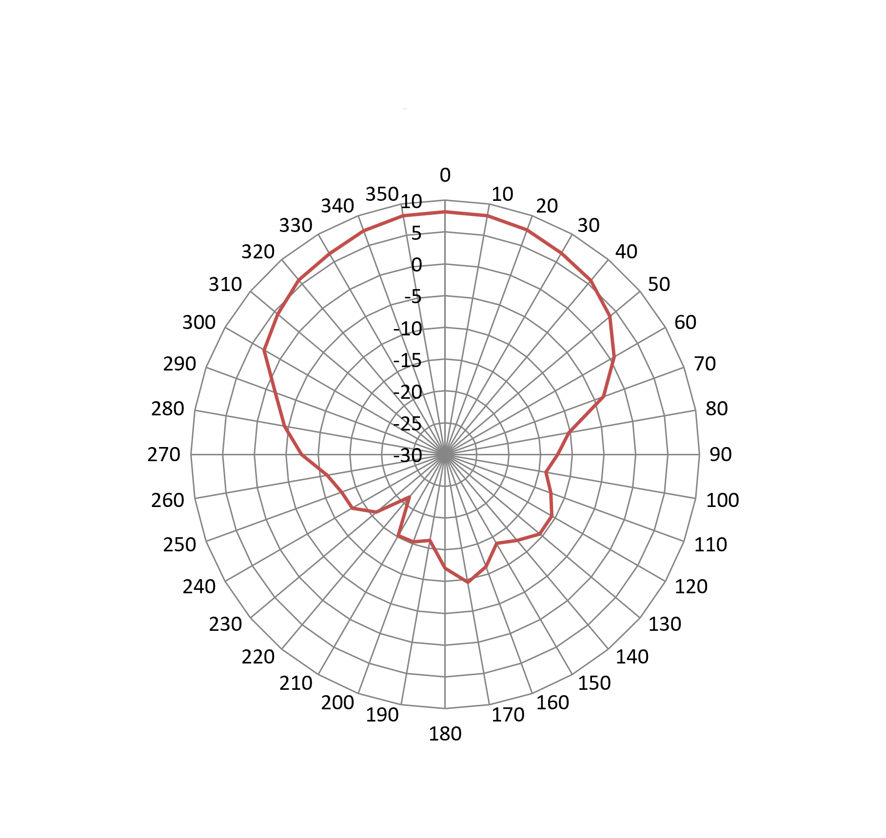 | 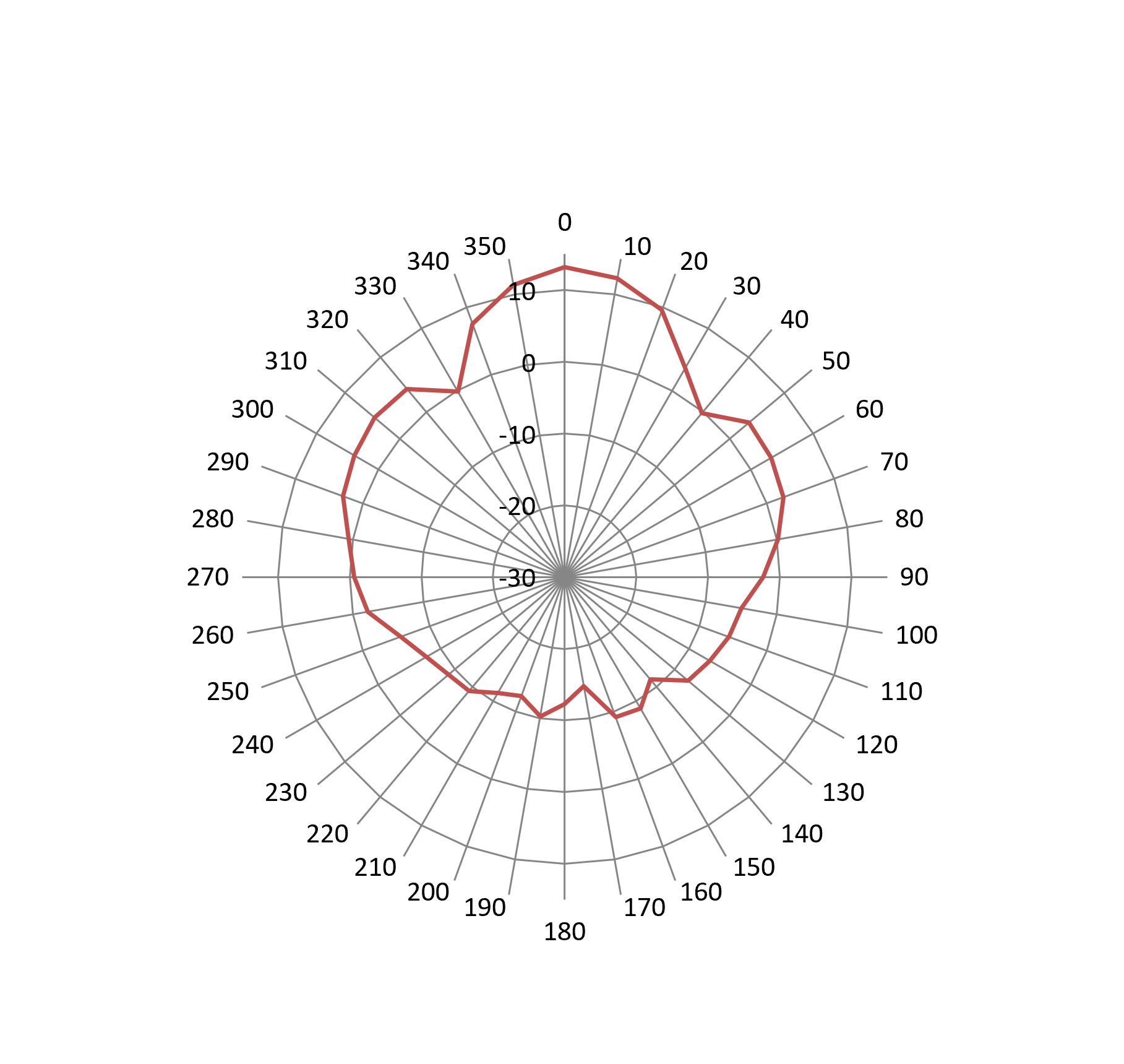 |
GWN7670LR Antenna Radiation Patterns (2.4 GHz / 5GHz)
- GWN7670LR Antenna Radiation Patterns (BT)
Label | 2.4G |
Phi=0(deg) XZ | 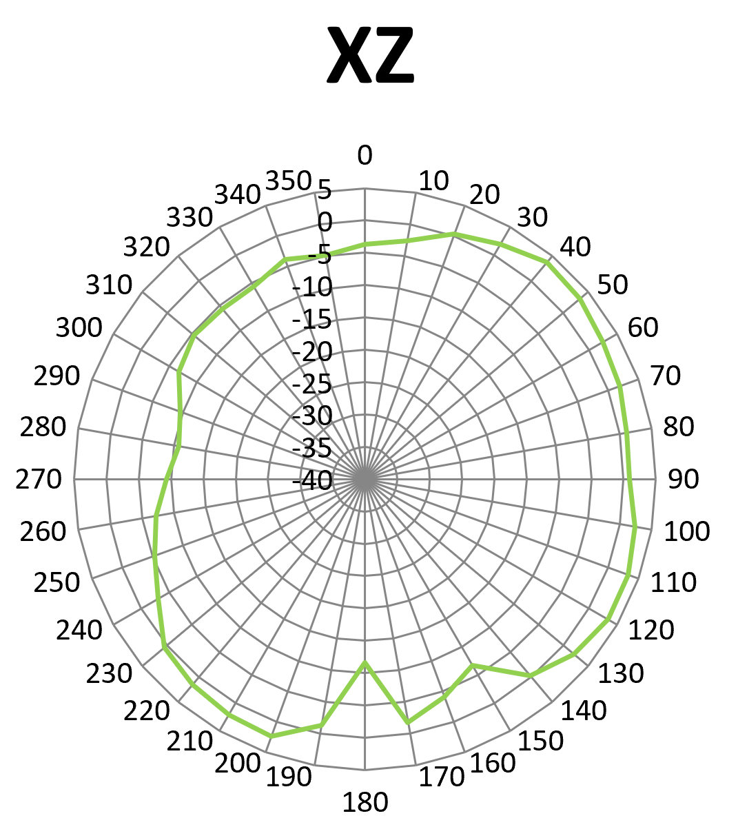 |
Phi=90(deg) YZ | 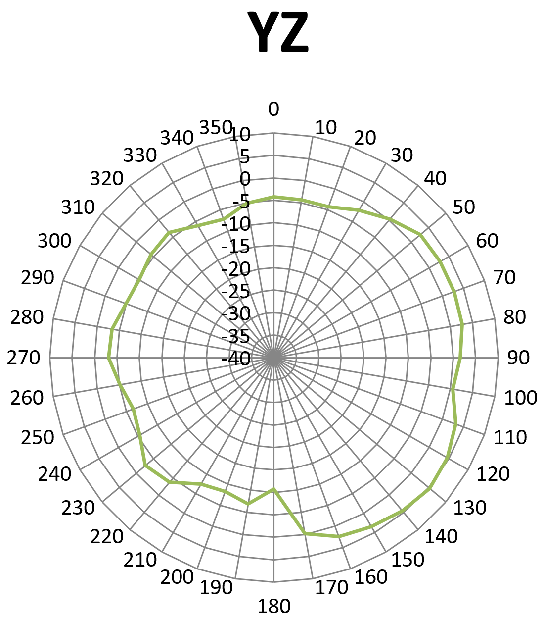 |
Theta=90(deg) XY | 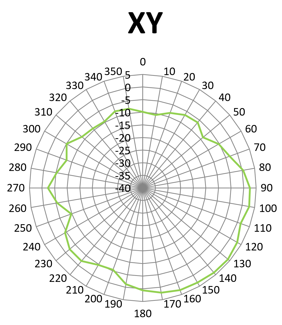 |
GWN7670LR Antenna Radiation Patterns (BT)
Tabular Antenna Gain Data
To complement the visual plots provided above, the following tables detail the precise numerical antenna gain values (measured in dBi) for the GWN7670LR access point. This raw data represents the signal strength distribution mapped at 10-degree increments across a full 360-degree radius. The values are categorized by frequency band (2.4 GHz and 5 GHz), the specific internal MIMO antennas (such as 2G0 and 2G1), and the respective measurement planes (XZ, YZ, and XY).
- 2.4G Antenna Gain Data
Angle | E Side | H Side |
0 | 8.37 | 8.21 |
10 | 8.22 | 8.13 |
20 | 7.66 | 7.58 |
30 | 6.75 | 6.56 |
40 | 5.43 | 5.68 |
50 | 3.98 | 3.86 |
60 | 1.32 | 0.69 |
70 | -1.56 | -3.45 |
80 | -4.74 | -10.23 |
90 | -10.43 | -12.33 |
100 | -7.41 | -13.92 |
110 | -8.46 | -12.33 |
120 | -10.93 | -10.65 |
130 | -12.21 | -10.55 |
140 | -13.33 | -12.33 |
150 | -12.66 | -13.83 |
160 | -14.35 | -11.21 |
170 | -16.87 | -9.56 |
180 | -12.72 | -12.11 |
190 | -13.33 | -16.28 |
200 | -14.73 | -15.36 |
210 | -14.25 | -15.29 |
220 | -14.38 | -21.23 |
230 | -14.23 | -15.83 |
240 | -12.42 | -13.13 |
250 | -9.35 | -12.65 |
260 | -7.53 | -11.12 |
270 | -6.18 | -7.45 |
280 | -2.65 | -4.38 |
290 | -2.11 | 4.55 |
300 | 3.26 | 2.86 |
310 | 5.13 | 4.38 |
320 | 5.77 | 5.82 |
330 | 7.12 | 6.45 |
340 | 8.22 | 7.44 |
350 | 8.38 | 8.17 |
- 5G Antenna Gain Data
Angle | E Side | H Side |
0 | 13.56 | 13.23 |
10 | 12.36 | 12.26 |
20 | 9.36 | 9.64 |
30 | 1.55 | 3.66 |
40 | -1.73 | -0.18 |
50 | 2.88 | 3.56 |
60 | 5.42 | 3.29 |
70 | 6.29 | 2.45 |
80 | 4.14 | 0.23 |
90 | 2.43 | -2.33 |
100 | -2.21 | -4.92 |
110 | -3.46 | -5.64 |
120 | -6.93 | -6.65 |
130 | -6.21 | -7.55 |
140 | -6.33 | -11.33 |
150 | -12.66 | -8.83 |
160 | -11.35 | -9.21 |
170 | -11.87 | -14.56 |
180 | -12.72 | -12.27 |
190 | -11.33 | -10.28 |
200 | -12.73 | -12.36 |
210 | -11.35 | -11.29 |
220 | -11.38 | -9.23 |
230 | -7.23 | -8.83 |
240 | -6.42 | -7.75 |
250 | -3.94 | -5.65 |
260 | -2.53 | -2.12 |
270 | 0.18 | -0.67 |
280 | 4.45 | 0.58 |
290 | 6.23 | 2.94 |
300 | 6.62 | 3.86 |
310 | 5.03 | 4.58 |
320 | 1.26 | 4.22 |
330 | -4.13 | -0.18 |
340 | 7.47 | 7.54 |
350 | 12.25 | 11.36 |
- BT Antenna Gain Data
Angle | Phi=0(deg) XZ | Phi=90(deg) YZ | Theta=90(deg) XY |
0 | -3.7 | -4.2 | -9.8 |
10 | -2.6 | -4.3 | -10.6 |
20 | 0.3 | -4.3 | -8.4 |
30 | 1.9 | -2.1 | -6.6 |
40 | 3.8 | 0.3 | -6.1 |
50 | 3.4 | 2.6 | -8.8 |
60 | 2.5 | 2.8 | -5.2 |
70 | 1.9 | 2.8 | -3.3 |
80 | 1.1 | 2.6 | 0.4 |
90 | 0.9 | 1.6 | 2.5 |
100 | 2.4 | 0.5 | 2.8 |
110 | 3.3 | 3.2 | 1.3 |
120 | 3.4 | 4.7 | 3.2 |
130 | 2.2 | 5.3 | 4.1 |
140 | -0.3 | 4.5 | 3.9 |
150 | -6.7 | 3.5 | 3.4 |
160 | -4.1 | 2.4 | 3.1 |
170 | -1.8 | -0.2 | 2.2 |
180 | -11.6 | -10.7 | 0.6 |
190 | -1.3 | -6.9 | -1.2 |
200 | 2.3 | -8.3 | -5.4 |
210 | 2.1 | -7.5 | -4.7 |
220 | 1.5 | -3.8 | -2.1 |
230 | 0.5 | -2.6 | -2.1 |
240 | -3.1 | -5.5 | -4.4 |
250 | -5.4 | -6.6 | -9.8 |
260 | -7.2 | -5.1 | -5.5 |
270 | -9.3 | -3.1 | -2.3 |
280 | -10.7 | -3.4 | -5.3 |
290 | -9.6 | -4.9 | -7.8 |
300 | -6.7 | -5.3 | -5.1 |
310 | -5.4 | -4.2 | -8.5 |
320 | -5.7 | -3.6 | -9.2 |
330 | -5.6 | -6.1 | -9.6 |
340 | -3.8 | -7.2 | -7.7 |
350 | -4.9 | -5.1 | -8.1 |