Introduction
The GWN7721 Series is a family of Layer 2 Lite managed multi-gigabit switches designed for small-to-medium businesses, hotels, home offices, and other high-speed network deployments. The series combines scalable wired connectivity, optional PoE for powering devices such as IP phones, cameras, and Wi-Fi access points, and flexible management through the local web interface, GWN Manager, GDMS Networking, and the GWN App.
| Model | Network Ports | PoE | Installation |
|---|---|---|---|
| GWN7721 | 8 × 2.5 GbE2 × 10G SFP+ | No PoENot supported | DesktopWall mount |
| GWN7721P | 8 × 2.5 GbE2 × 10G SFP+ | PoE/PoE+8 ports · Up to 30 W per port130 W total budget | DesktopWall mountRack mount |
| GWN7721PE | 8 × 2.5 GbE1 × 10 GbE1 × 10G SFP+ | PoE++Ports 1–8: PoE/PoE+, up to 30 W eachPort 9: PoE/PoE+/PoE++, up to 90 W130 W total budget | DesktopRack mount |
Precautions
- Do not open, disassemble, or modify the device.
- Operate the device at 0–45 °C and store it at -20–60 °C.
- Keep the device in an environment with 10–90% relative humidity (non-condensing).
- Use supported Ethernet connections: 10/100/1000/2500 Mbps, the 10 Gbps RJ45 port on GWN7721PE, and SFP+.
- For PoE output, GWN7721P supports up to 30 W per PoE port. On GWN7721PE, ports 1–8 support up to 30 W each and port 9 supports up to 90 W.
- Keep the grounding wire securely connected while the device is in use.
Package Content

Rack Mounting (GWN7721P/GWN7721PE)
- Attach the four rubber feet to the marked locations on the bottom of the switch for desktop installation.
- For rack installation, align the supplied rack-mount brackets with the screw holes on both sides of the switch.
- Secure the brackets to the switch with the supplied KM 3 × 6 mm screws.
- Place the switch in the rack and secure both brackets to the rack.

Power and Grounding
- Connect the supplied 12 V power adapter to the GWN7721, or connect the supplied AC power cord to the GWN7721P/GWN7721PE.
- Connect one end of the grounding cable to the grounding point on the switch.
- Connect the other end to a suitable grounding point and verify that the connection is secure before powering on the switch.
Network Setup
- Connect a router, gateway, computer, access point, IP phone, or other network device to an Ethernet port on the switch.
- Use the 10G SFP+ port or ports for a compatible fiber or high-speed uplink when required.
- For GWN7721P, connect PoE devices to ports 1–8. Each port supports up to 30 W.
- For GWN7721PE, connect PoE/PoE+ devices to ports 1–8 (up to 30 W per port). Use port 9 for a 10G PoE/PoE+/PoE++ device requiring up to 90 W.
- Confirm that all cables are securely connected and that the required port LEDs are active.

LED Light Indicators
The GWN7721P provides eight yellow PoE supply LEDs. The GWN7721PE provides nine yellow PoE supply LEDs, including the indicator for the 10 GbE PoE++ port.
| LED Indicator | Status | Description |
|---|---|---|
| System Indicator | Off | Power off |
| Green On | Power on | |
| Green Flashing | Upgrade in progress | |
| Blue On | Normal operation | |
| Blue Flashing | Provisioning | |
| Red On | Upgrade failed | |
| Red Flashing | Factory reset in progress | |
| Port Indicator | Off | No connected device or abnormal connection |
| Green On | Port connected with no data activity | |
| Green Flashing | Port connected and transferring data | |
| PoE LED (GWN7721P/GWN7721PE) | Off | PoE power is not being supplied |
| Yellow On | PoE power is being supplied normally after negotiation with the powered device | |
| Yellow Flashing | PoE power anomaly, such as port overload or PSE throttling |
Web GUI Access
- Connect a computer to the same network as the switch.
- Open a web browser and enter
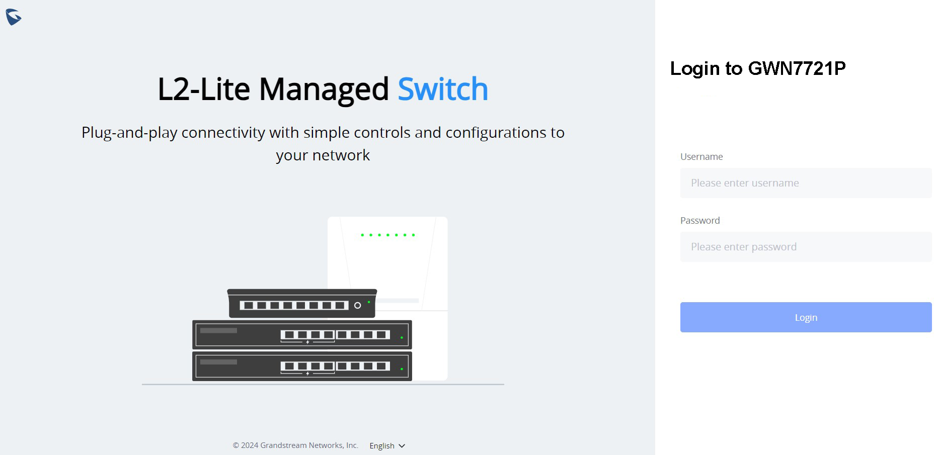
http://192.168.0.254. If the switch received an address from a DHCP server, enter its assigned IP address instead. - Sign in with the administrator credentials and configure the switch as required.
- Alternatively, add and manage the switch through GDMS Networking, GWN Manager, or the GWN App.