


The GWN7710R is a 6-Port (5GE+1SFP) Outdoor Lite Managed PoE Switch with a professional shell design, IP66 dust-proof and waterproof which can easily cope with rain, snow, high temperatures and other harsh weather conditions. The GWN7710R can build scalable, secure, high-performance, easy to use and manage business networks in scenic locations, hotels, restaurants and other similar areas. It supports not only flexible and complex traffic segmentation by VLAN, but also port-based, DSCP/802.1p QoS priority management modes, as well as bandwidth control and Storm Control, greatly improving the overall network performance.The GWN7710R integrates PoE power supply and PoE power receive, which results in multi-port long-distance PoE power supply while extending the data transmission distance. It can be managed in a variety of ways, including the local web user interface and GWN. Cloud. The compact body of GWN7701R and its support for pole and wall-mounted installation make it the ideal management network switch for both indoor and outdoor areas.
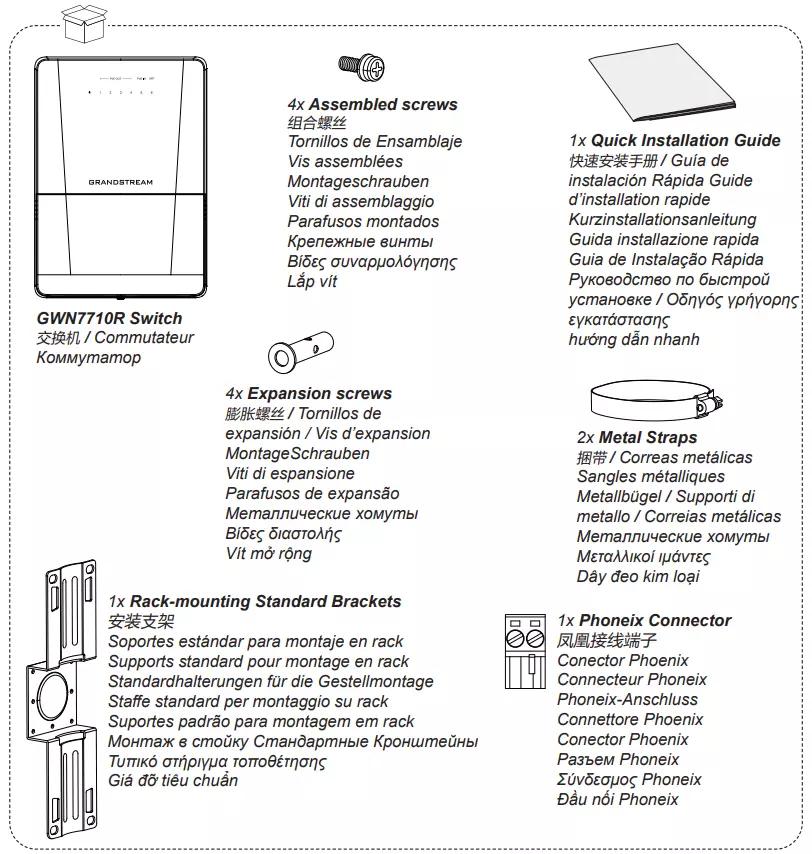
Package Contents
Pole Mount
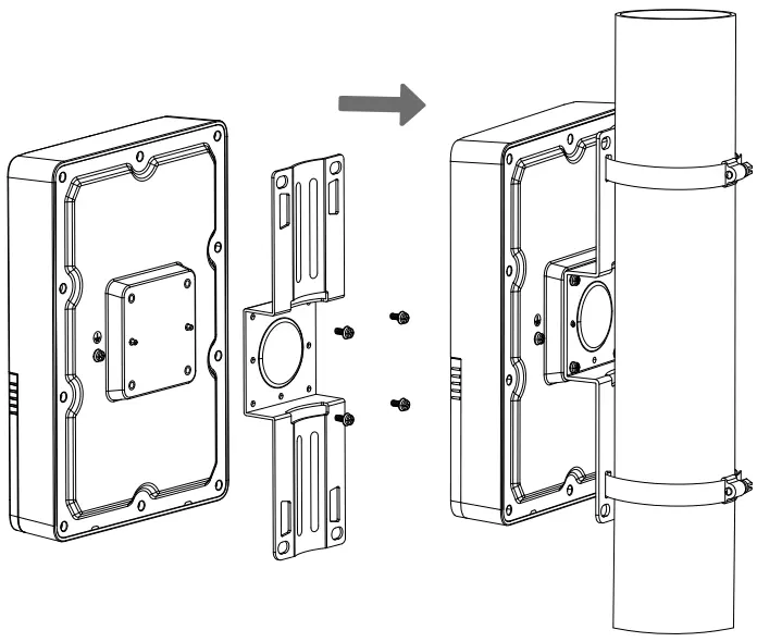
- Attach the bracket to the back of the unit using the assembled screws.
- Open the metal straps by turning the locking mechanism counter-clockwise. You can loosen it by hand or use a flathead screwdriver.
- Straighten out the end of the metal straps and slide it through the back of the bracket.
- Wrap the metal strap around the pole and use a flathead screwdriver to tighten the locking mechanism by turning it clockwise.
Wall Mount
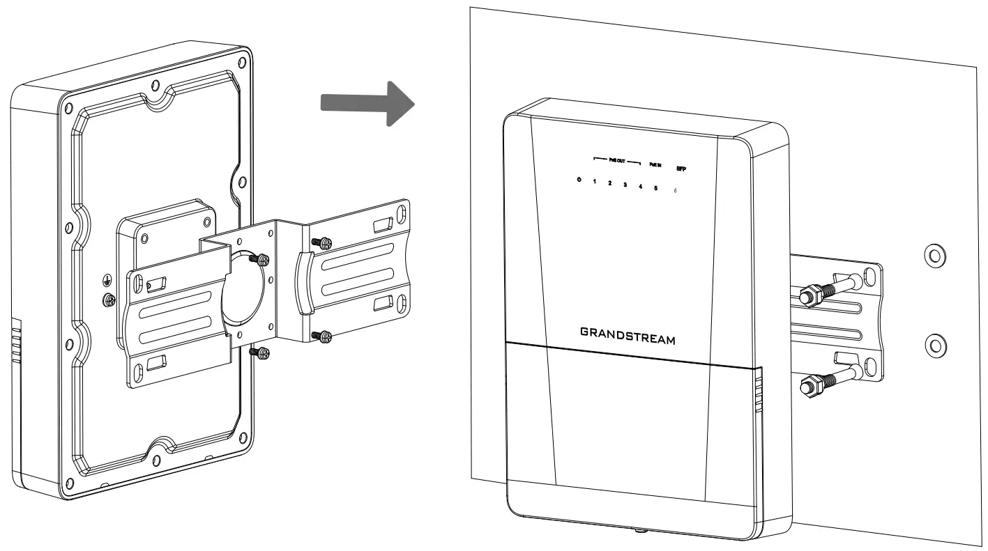
- Rotate the bracket 90° and attach it horizontally on the back of the device with assembled screws.
- Drill four holes on the wall referring to the positions of the ones on the bracket. Then, fix an expansion screw in each hole.
- Attach the device by securing the bracket with the expansion screws on the wall.
DIN-Rail Mount
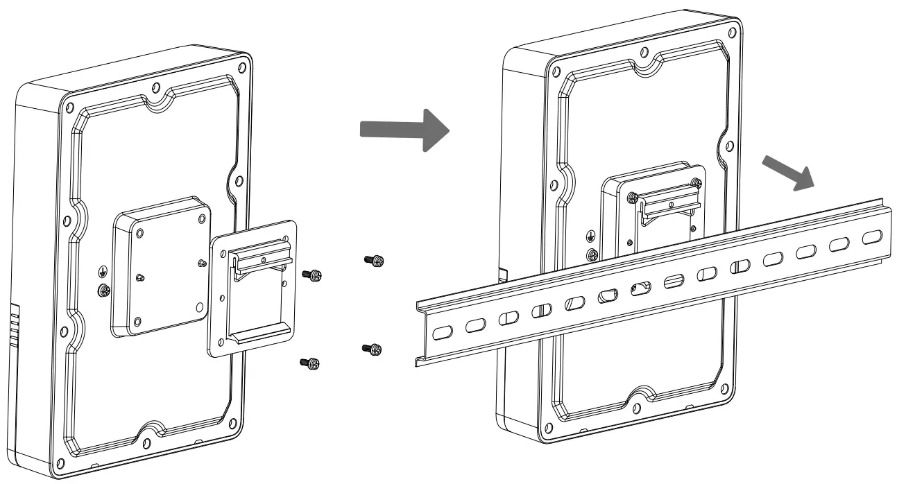
- Attach the DIN-Rail bracket with screws on the back of the device.
- Clamp the DIN-Rail bracket to the universal guide rail.
Grounding the Switch
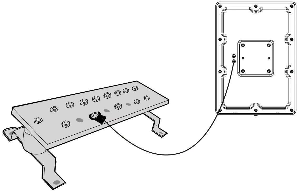
- Remove the ground screw from the back of switch, and connect one end of the ground cable to the wiring terminal of switch.
- Put the ground screw back into the screw hole, and tighten it with a screwdriver.
- Connect the other end of the ground cable to other device that has been grounded or directly to the terminal of the ground bar in the equipment room.
Cable Installation
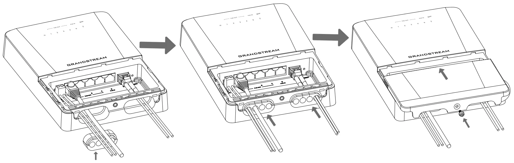
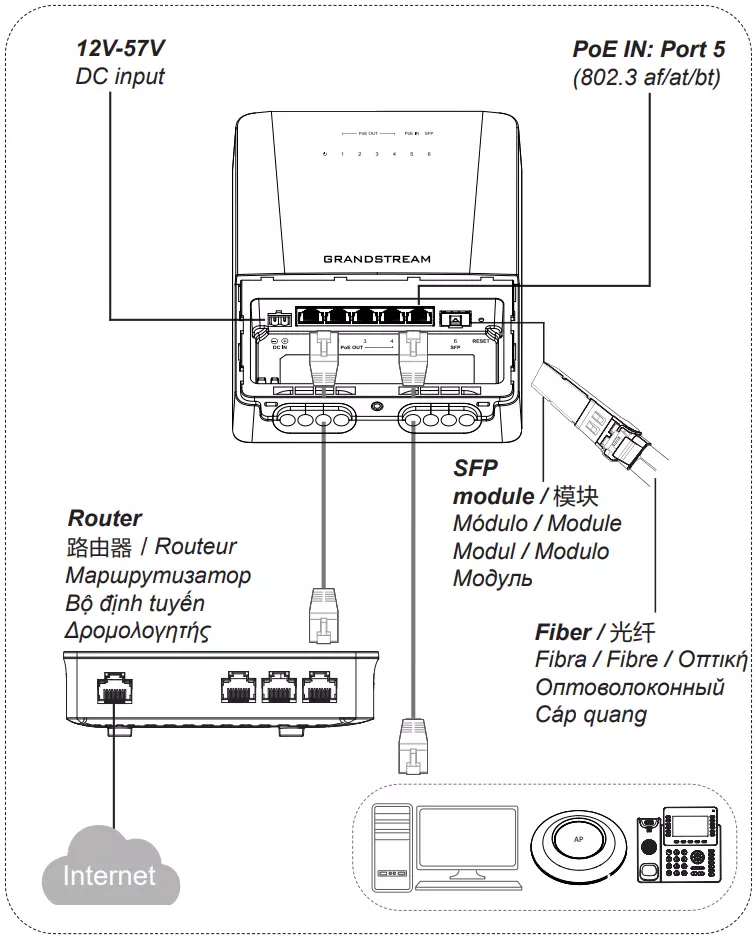
- Insert the cable through the hole under the device housing and connect it to the corresponding interface, then insert the other end of the cable into the waterproof silicone plug.
- Insert the waterproof silicone plug into the designated position under the device housing.
- Push the anti-water shell in the direction of the arrow until the bottom shell is completely closed, and then use screws to fix it.
Access & Configure
Method 1: Login using the Web UI
- A PC uses a network cable to correctly connect any RJ45 port of the switch.
- Set the Ethernet (or local connection) IP address of the PC to 192.168.0.x (“x” is any value between 1-253), and the subnet mask to 255.255.255.0, so that it is in the same network segment with switch IP address. If DHCP is used, this step could be skipped.
- Type the switch’s management IP address http://(gwn7710R_IP) in the browser, and enter username and password to login. (The default administrator username is “admin” and the default random password can be found at the sticker on the GWN7710R switch).
Method 2: Configure using GDMS/GWN Manager
Type https://www.gdms.cloud (https://<gwn_manager_IP> for GWN Manager) in the browser, and enter the account and password to login the cloud platform. If you don’t have an account, please register first or ask the administrator to assign one for you. To add GWN switch to GDMS/GWN manager refer to online documentation: https://documentation.grandstream.com.
LED Indicator
LED Indicator | Status | Description | |
Power | Green | Off | Power off |
On | System power on | ||
Red | On | Low temperature starting | |
PoE Out Port | Green | On | Link |
Flashing | Active | ||
Orange | On | 48VDC PoE output; (Force on when passive PoE mode) | |
1S On 1S Of | 48VDC PoE output overload/Short-circuit | ||
Blue | On | 24VDC PoE output; (Force on when passive PoE mode) | |
1S On 1S Of | 24VDC PoE output overload/Short-circuit | ||
PoE In Port | Green | On | Link |
Flashing | Active | ||
Orange | On | Powered by PoE In | |
SFP | Green | On | Link |
Flashing | Active | ||
GWN7710R LED Indicator
Refer to online documents and FAQ for more detailed information:
https://www.grandstream.com/our-products

For Certification, Warranty, and RMA information, please visit: www.grandstream.com