Overview
VLAN stands for virtual LAN and it allows segmenting of a local area network into many logical networks. Moreover, In this guide, we will explore the remarkable capabilities of GWN78XX(P) switches, specifically their support for up to 4094 VLANs. , these switches enable the isolation of hosts at Layer 2, effectively limiting broadcast domains and bolstering network security.
To learn more about VLAN, please refer to RFC2674 standard
VLAN Configuration Example
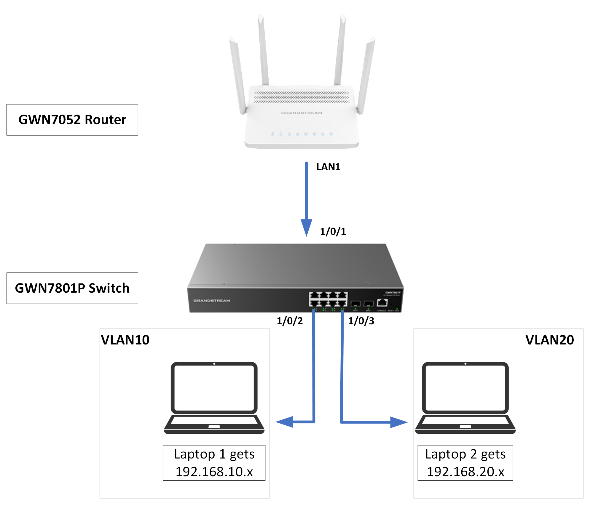
VLAN feature enables GWN78xx switches to segment the physical local area network to many logical area networks. In this lab, we’re going to assign two different network addresses to two VLANs using a GWN router.
Router Configuration
First, we should configure the VLANs on the router, to do that follow the steps below.
- Log in to the WebUI of the router, then navigate to Network Settings → LAN.
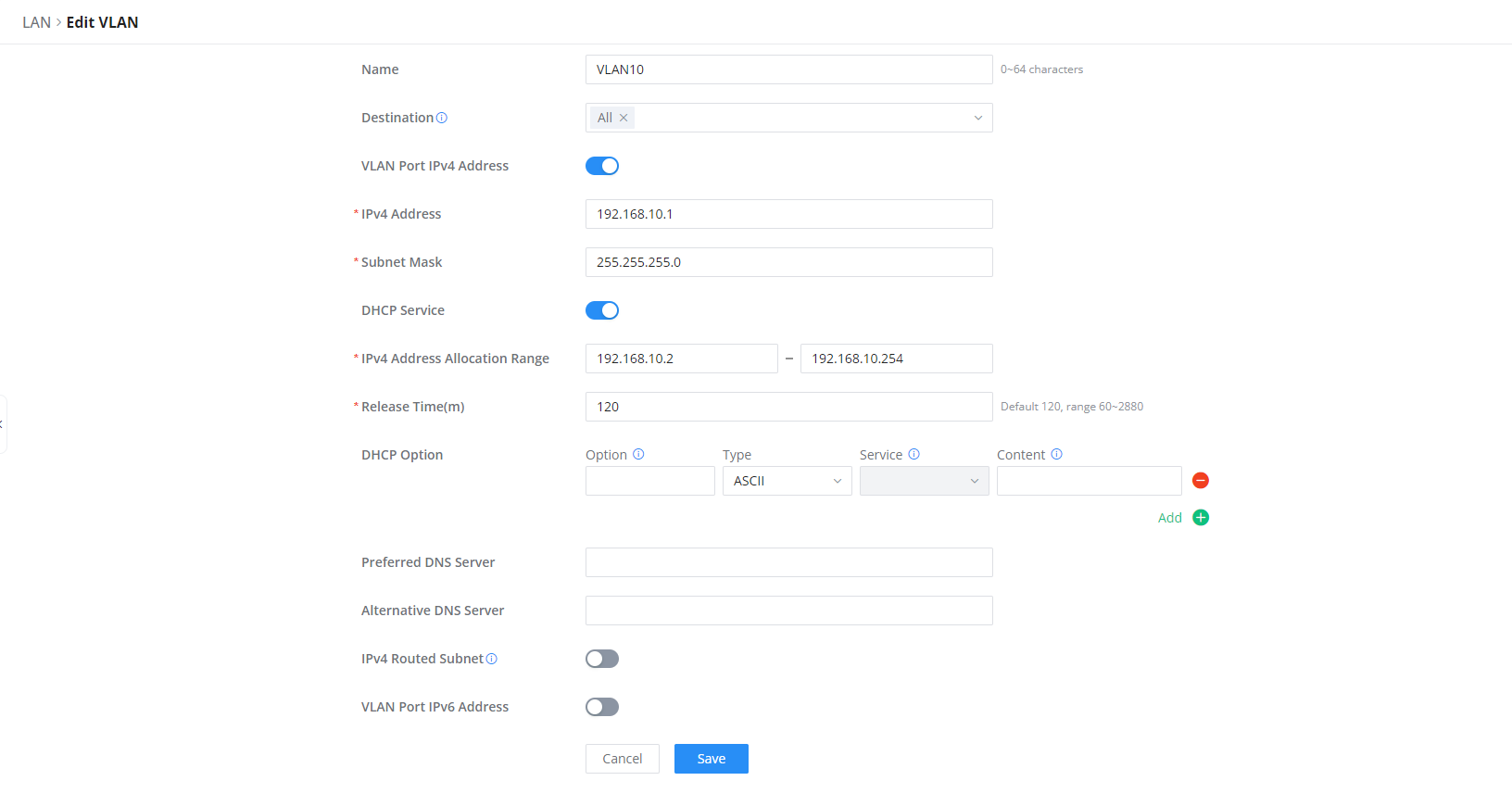
- Click “Add” on VLAN tab and configure the following for the first VLAN:
- Enter “10” in the VLAN ID.
- Enable VLAN port IP address then enter 192.168.10.1, use 255.255.255.0 as the subnet mask
- Enable DHCP Service, then specify the DHCP range 192.168.10.2 – 192.168.10.255
- Click “Save”
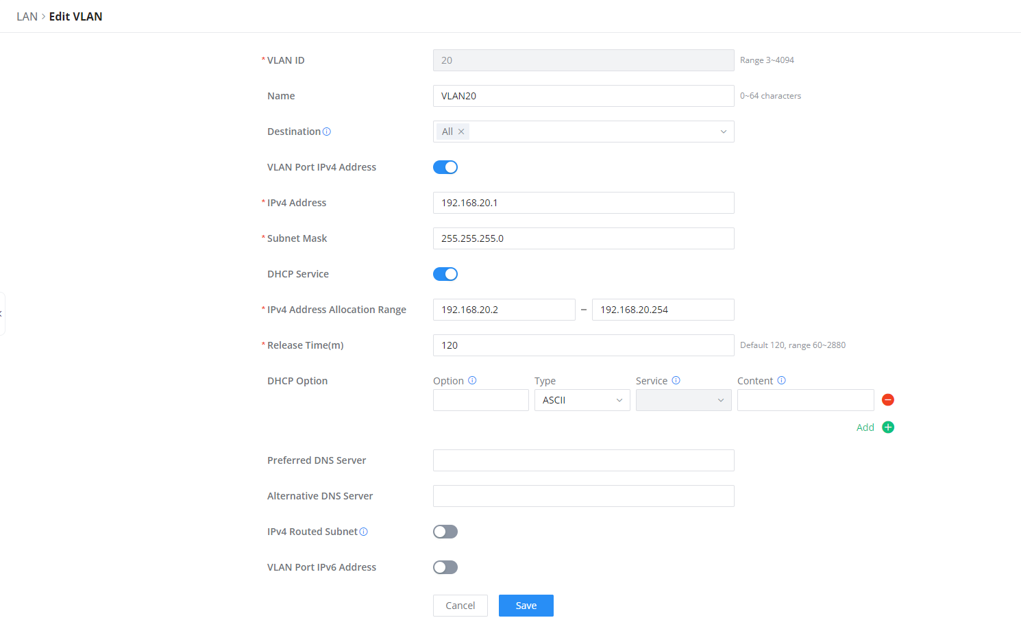
3. Click “Add” again and enter the following configuration for the second VLAN:
- Enter “20” in the VLAN ID.
- Enable VLAN port IP address then enter 192.168.20.1, use 255.255.255.0 as the subnet mask.
- Enable DHCP Service, then specify the DHCP range 192.168.20.2 – 192.168.20.254
- Click “Save”
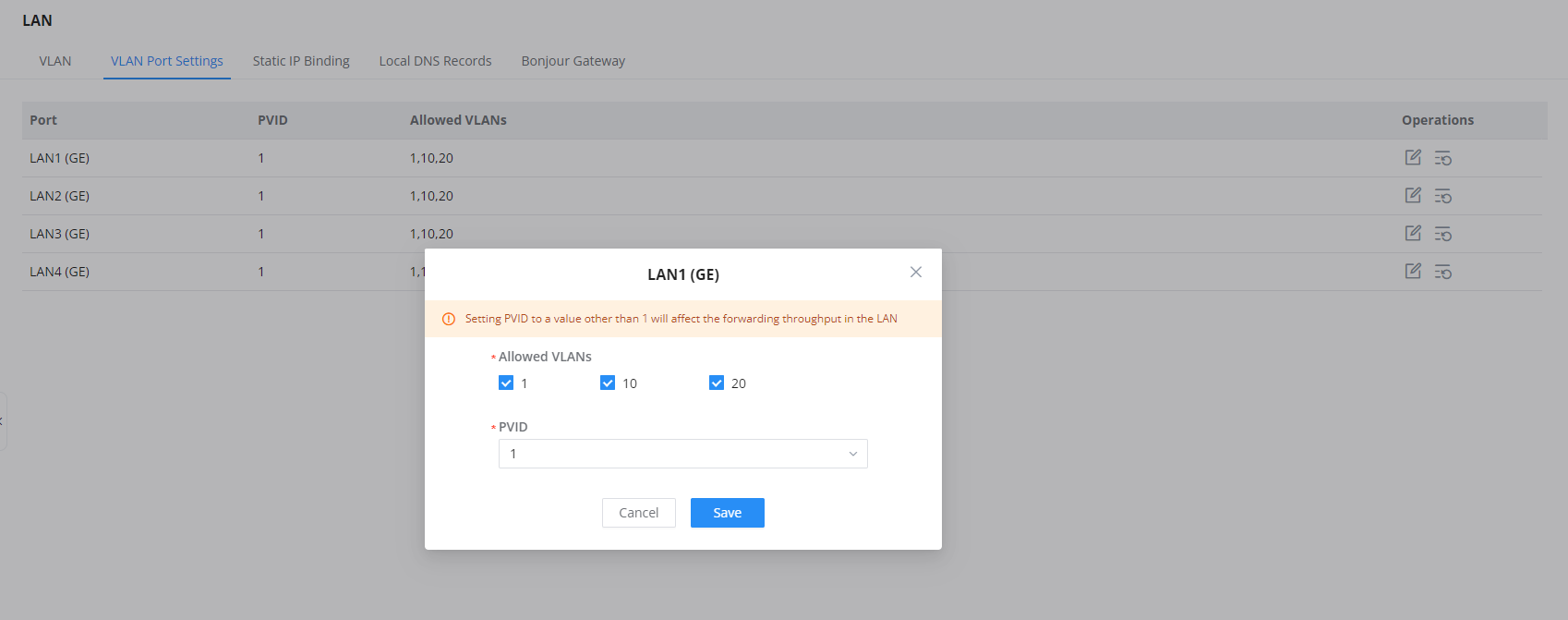
4. On the “VLAN Port Settings” section, make sure that the allowed VLANs on LAN1 include VLAN10 and VLAN20 that we have configured. the Default VLAN (VLAN1) should be selected as well.
Switch configuration
Now, we will move to the switch configuration.
1. log in to the web UI of the GWN switch, then navigate to Switching → VLAN.
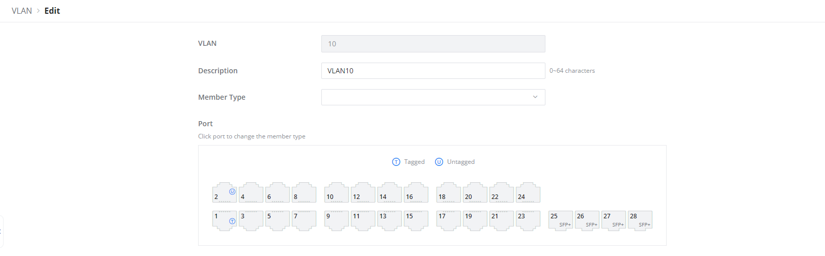
2.Add VLAN “10” and VLAN “20”
3. On VLAN “10” set Ports to be as follows: Port 1 as the Trunk port (Tagged Port) and Port 2 as the Access port (Untagged Port)
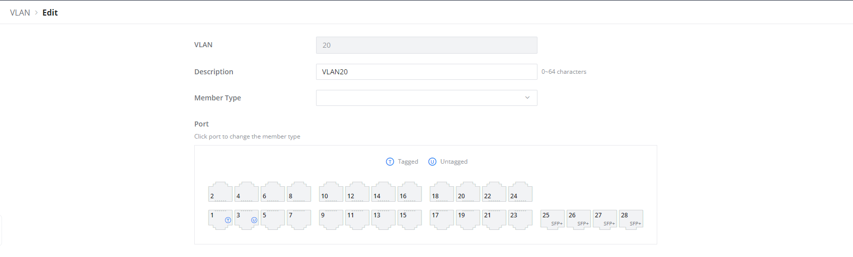
4. With the same way repeated on VLAN “20”, we get Port 1 set as Trunk Port (Tagged Port) and Port 3 set as an Access port (Untagged Port),
4. Navigate to the Port Settings tab and click on 1/0/1, make sure that Link Type is set to Trunk. Click “Save”.

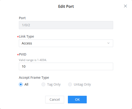
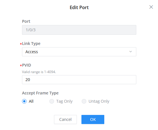
5. Edit the ports 1/0/2 and 1/0/3, set their Link Type as Access, then enter the Port VLAN ID (PVID) as 10 and 20, respectively. Click “Save”.
6. Save the running configuration into the saved configuration by clicking on “Save” in the top right corner of the web UI.
Finally, Connect the laptop 1 to 1/0/2, and you should be able to get the IP address 192.168.10.x on the laptop, Connect the laptop 2 to 1/0/3, and you should be able to get the IP address 192.168.20.x on the laptop.
Supported Devices
Device Name | Supported | Firmware Required |
GWN7801 | Yes | 1.0.3.19 or higher |
GWN7801P | Yes | 1.0.3.19 or higher |
GWN7802 | Yes | 1.0.3.19 or higher |
GWN7802P | Yes | 1.0.3.19 or higher |
GWN7803 | Yes | 1.0.3.19 or higher |
GWN7803P | Yes | 1.0.3.19 or higher |
GWN7811 | Yes | 1.0.1.8 or higher |
GWN7811P | Yes | 1.0.1.8 or higher |
GWN7812P | Yes | 1.0.1.8 or higher |
GWN7813 | Yes | 1.0.1.8 or higher |
GWN7813P | Yes | 1.0.1.8 or higher |
GWN7806 | Yes | 1.0.1.14 or higher |
GWN7806P | Yes | 1.0.1.14 or higher |
GWN7816 | Yes | 1.0.3.8 or higher |
GWN7816P | Yes | 1.0.3.8 or higher |
GWN7830 | Yes | 1.0.3.3 or higher |
GWN7831 | Yes | 1.0.3.3 or higher |
GWN7832 | Yes | 1.0.3.3 or higher |
List of Supported Devices