
Thank you for purchasing the Grandstream GXW42XX Analog FXS IP Gateway. The GXW42XX offers an easy to manage, easy to configure IP communications solution for any business with virtual and/or branch locations. The GXW42XX supports popular voice codecs and is designed for full SIP compatibility and interoperability with third party SIP providers, thus enabling you to fully leverage the benefits of VoIP technology, integrate a traditional phone system into a VoIP network, and efficiently manage communication costs.
This manual will help you learn how to operate and manage your GXW FXS Analog IP Gateway and make the best use of its many upgraded features including simple and quick installation, multi-party conferencing, and direct IP-IP Calling. This IP Analog Gateway is very easy to manage and scalable, specifically designed to be an easy to use and affordable VoIP solution for the small – medium business or enterprise.
GATEWAY GXW42XX OVERVIEW
The new GXW42XX series has a compact and quiet design and offers superb audio quality, rich feature functionality, strong security protection, and good manageability. It is auto-configurable, remotely manageable and scalable.
The GXW42XX series features 16, 24, 32 or 48port FXS interface for analog telephones, dual 10/100/1000Mbps network ports, and RJ21analog port. In addition, it supports the option of 4 SIP Server profiles, caller ID for various countries/regions, T.38 fax, flexible dialing plans, security protection (SIPS/TLS), comprehensive voice codec including G.711 (a/u-law), G.723.1, G.726(16/24/32/40 bit rates), iLBC and G.729.
CONNECT YOUR GXW42XX GATEWAY
Connecting the GXW42XX gateway is easy. Before you begin, please verify the contents of the GXW42XX package.
Equipment Packaging
Unpack and check all accessories. Equipment includes:
- one device unit
- one RJ45 Ethernet cable
- one 12V 5A universal power adapter (24V 6.25A for GXW4248)
- mount
Connect the GXW42XX
Follow these four (4) steps to connect your GXW42XX gateway to the Internet and access the unit’s configuration pages.
- Connect standard touch-tone analog phones to the GXW42XX’s RJ21 port with a RJ11 to R21 cable.
- Insert anRJ45 Ethernet cable into the WAN port of GXW42XX and connect the other end to an uplink port (a router or a modem, etc.)
- Plug the power adapter into the GXW42XX gateway into a power outlet.
Follow the instructions from the topic “Configuring GXW 42XX with Web Browser” for initial configuration. The GUI pages will guide you through the remaining steps to set-up your gateway.
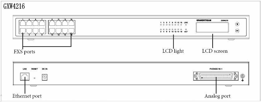
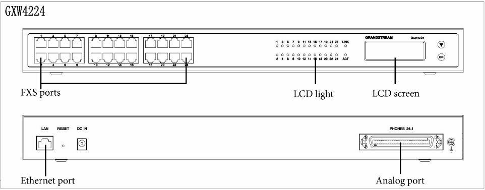
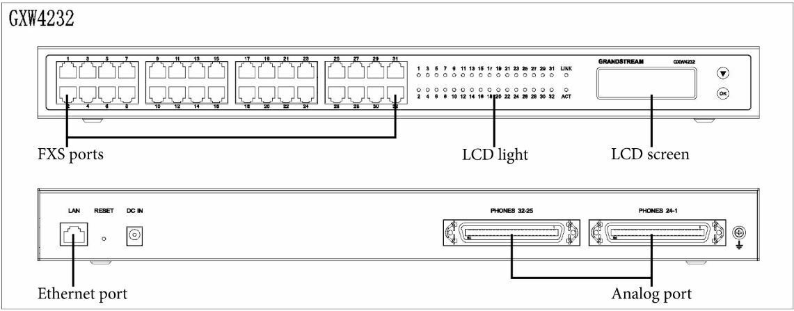
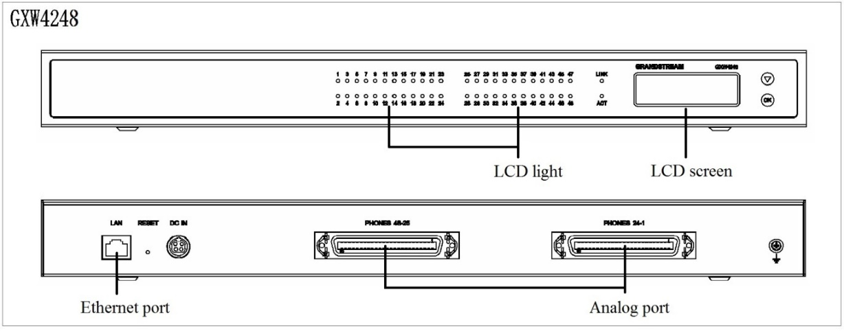
Ethernet port | Connect to the internal LAN network or router |
RESET | Factory Reset button. Press and hold for a while to reset factory default settings. |
DC IN | Power adapter connection |
Analog port | Connect to analog phones / fax machines with an RJ21 to RJ11 cable |
FXS ports | FXS port to be connected to analog phones / fax machines. |
Definitions of the GXW Connectors
Act LED | Remains ON if plug the network cable. |
LINK LED | Indicates Ethernet port activity. |
FXS LED | Indicate status of the respective FXS Ports on the back panel
Busy – ON (Solid Green) Available – OFF
Slow blinking FXS LEDs indicates Voice Mail for that port.
All FXS LEDs slow blinking indicates provisioning. |
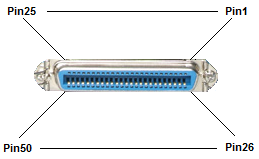
Pin | Signal | Pin | Signal |
1 | RING1 | 26 | TIP1 |
2 | RING2 | 27 | TIP2 |
3 | RING3 | 28 | TIP3 |
4 | RING4 | 29 | TIP4 |
5 | RING5 | 30 | TIP5 |
6 | RING6 | 31 | TIP6 |
7 | RING7 | 32 | TIP7 |
8 | RING8 | 33 | TIP8 |
9 | RING9 | 34 | TIP9 |
10 | RING10 | 35 | TIP10 |
11 | RING11 | 36 | TIP11 |
12 | RING12 | 37 | TIP12 |
13 | RING13 | 38 | TIP13 |
14 | RING14 | 39 | TIP14 |
15 | RING15 | 40 | TIP15 |
16 | RING16 | 41 | TIP16 |
17 | RING17 | 42 | TIP17 |
18 | RING18 | 43 | TIP18 |
19 | RING19 | 44 | TIP19 |
20 | RING20 | 45 | TIP20 |
21 | RING21 | 46 | TIP21 |
22 | RING22 | 47 | TIP22 |
23 | RING23 | 48 | TIP23 |
24 | RING24 | 49 | TIP24 |
50 Pin Telco Connector
GXW42XX FEATURES
The GXW42XX is a next generation IP voice gateway that is interoperable and compatible with leading IP-PBXs, Soft switches and SIP platforms. The GXW42XX FXS gateway is auto-configurable, remotely manageable and scalable. The GXW42XX gateways come in four models – the GXW4216, GXW4224, GXW4232and GXW4248, each offering superb voice quality, traditional telephony functionality, easy deployment, and 16, 24,32 and 48FXS ports respectively. Each model features flexible dialing plans, integrated call routing to support a pure IP network call and an external power supply.
Software Features Overview
- 16, 24, 32 or 48FXS ports (no front panel FXS ports on GXW4248)
- RJ-45 Ethernet ports
- 4 configurable SIP profiles
- Supports Voice Codecs:
G711 (a/µ, Annex I & II), G723.1A, G726 (ADPCM with 16/24/32/40 bit rates), G729 A/B, iLBC, T.38 Fax
- Comprehensive Dial Plan support for Outgoing calls.
- G.168 Echo Cancellation,
- Voice Activation Detection (VAD), Comfort Noise Generation (CNG), and Packet Loss Concealment (PLC)
- Supports PSTN/PBX analog telephone sets or analog trunks
GXW4216 | GXW4224 | GXW4232 | GXW4248 | |
Telephone Interfaces | 16 FXS ports | 24 FXS ports | 32 FXS ports | 48 FXS ports |
SIP Provisioning | 16 SIP accounts, 4 profiles | 24 SIP accounts, 4 profiles | 32 SIP accounts, 4 profiles | 48 SIP accounts, 4 profiles |
Network Interface | 10/100/1000 Mbps, RJ-45 | |||
Number of Concurrent Calls (except when using SRTP) | 16 Concurrent Calls | 24 Concurrent Calls | 32 Concurrent Calls | 48 Concurrent Calls |
Voice over Packet Capabilities | Voice Activity Detection (VAD) with CNG (comfort noise generation) and PLC (packet loss concealment), LEC with NLP Packetized Voice Protocol Unit (supports RTP and AAL2 protocol), G.168 compliant Echo Cancellation, Dynamic Jitter Buffer, Modem detection & auto-switch to G.711 | |||
Voice Compression | G.711 + Annex I (PLC), Annex II (VAD/CNG format) encoder and decoder, G.722, G.723.1A, G.726(ADPCM with 16/24/32/40-bit rates), G.729, iLBC, G.726 provides proprietary VAD, CNG, and signal power estimation, Voice Play Out unit (reordering, fixed and adaptive jitter buffer, clock synchronization), AGC (automatic gain control), Status output, Decoder controlling via voice packet header | |||
DHCP Server/Client | DHCP Client only | |||
Fax over IP | T.38 compliant Group 3 Fax Relay up to 14.4kpbs and auto-switch to G.711 for Fax Pass-through, Fax Datapump V.17, V.21, V.27ter, V.29 for T.38 fax relay | |||
QoS | DiffServ, TOS, 802.1P/Q VLAN tagging | |||
Transport Protocol | RTP | |||
DTMF Method | In-audio, RFC2833, and/or SIP Info | |||
IP Signaling | SIP (RFC 3261) | |||
Provisioning | TFTP, HTTP, HTTPS | |||
Security | SRTP, TLS/SIPS, HTTPS, 802.1x | |||
Management | Syslog support, HTTP/HTTPS and SSH access | |||
Dial Plan | Yes | |||
3-way Conference | 3-Way conference with local mixing | |||
Caller ID | Bellcore Type 1 & 2, ETSI, BT, NTT, FSK and DTMF-based CID | |||
Polarity Reversal / Wink | Yes | |||
Network Connectivity | IPv4, TCP/UDP, RTP, HTTP/HTTPS, ARP/RARP, ICMP, DNS, DHCP, NTP, TFTP, SSH, PPPoE, STUN, DDNS, OpenVPN® | |||
Table 3: GXW42xx Software Specifications
Hardware Specification
The hardware specifications of the GXW FXS series are detailed in Table 4.
GXW4216 | GXW4224 | GXW4232 | GXW4248 | |
Telephone Interfaces | 16 RJ11 Ports/ 1 RJ21 Port | 24 RJ11 Ports/ 1 RJ21 Port | 32 RJ11 Ports/ 2 RJ21 Ports | 2 RJ21 Ports only |
FXS LEDs | 16 | 24 | 32 | 48 |
Network Interface | LAN, Single 10/100/1000 BASE-TX, RJ45 | |||
Power Input | Input:100-240VAC, 50/60Hz Output: 12V DC, 5.0A (4216/24/32) 24V DC, 6.25A (4248 only) | |||
LCD Screen | 128x32 pixel | |||
Telco Connector | 1 RJ21 (50 pins) | 1 RJ21 (50 pins) | 2 RJ21 (50 pins) | 2 RJ21 (50 pins) |
RJ-11 Connectors | Yes | Yes | Yes | No |
Function Buttons | 1 button for Reset/Factory Reset | |||
Environmental | Operation: 0°C to 45°C Storage: -20°C to 60°C Humidity: 10% to 90% Non-condensing | |||
Mounting | Desktop and Rack mount | |||
On-hook Voltage | Fixed, 48V | |||
Ring Voltage | 50Vrms (balanced ringing) | |||
Ring Frequency | 20-50 Hz | |||
Short Haul Loop | 2REN: Up to 2km on 24 AWG wire | 2REN: Up to 2km on 24 AWG wire | 2REN: Up to 2km on 24 AWG wire | 2REN: Up to 2km on 24 AWG wire |
Outdoor Protection | Over-voltage Protection and surge immunity | |||
Signaling | FXS Loop-start | |||
EMC | EN55022/EN55024 and FCC part15 Class B | |||
Safety | UL | |||
Compliance | FCC, CE, C-Tick | |||
GXW42xx Hardware Specifications
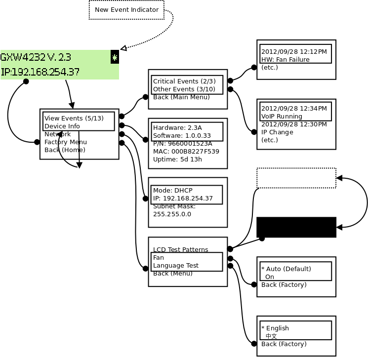
GXW42XX LCD Menu
The GXW42XX gateway series includes a small LCD screen for the display of basic information. The LCD has a display area of 128×32 pixels, which will allow for 2 lines of text with a 16px height limitation per line.
The LCD menu is showed as Figure 3: LCD Menu. Menu is navigated by the Down-arrow and OK button.
BASIC OPERATIONS
Understanding GXW Voice Prompts
GXW42XX has a built-in voice prompt menu for simple device configuration. To enter the voice prompt menu, press *** on the standard analog phone which is connected to device’s FXS port.
Menu | Voice Prompt | User’s Options |
Main Menu | “Enter a Menu Option” | Enter “*” for the next menu option Enter “#” to return to the main menu Enter “001 – 005,007, 010, 013 – 017,047, 086 or 099” Menu option Enter “9” for confirming an option |
001 | “DHCP Mode”, “PPPoE Mode” or “Static IP Mode” | Enter ‘9’ to toggle the selection
If user selects “Static IP Mode”, user need configure all the IP address information through menu 002 to 005. If user selects “Dynamic IP Mode”, the device will retrieve all IP address information from DHCP server automatically when user reboots the device. |
002 | “IP Address “ + IP address | The current WAN IP address is announced Enter 12-digit new IP address if in Static IP Mode.
|
003 | “Subnet “ + IP address | Same as Menu option 002 |
004 | “Gateway “ + IP address | Same as Menu option 002 |
005 | “DNS Server “ + IP address | Same as Menu option 002 |
007 | Preferred Vocoder | Enter “9” to go to the next selection in the list: PCMU PCMA iLBC G-726 G-723 G-722 G-729
|
010 | “MAC Address” | Announces the Mac address of the unit. |
013 | Firmware Server IP Address | Announces current Firmware Server IP address. Enter 12-digit new IP address. |
014 | Configuration Server IP Address | Announces current Config Server Path IP address. Enter 12-digit new IP address.
|
015 | Upgrade Protocol | Upgrade protocol for firmware and configuration update. Enter “9” to toggle between TFTP and HTTP |
016 | Firmware Version | Firmware version information. |
017 | Firmware Upgrade | Firmware upgrade mode. Enter “9” to rotate among the following three options: 1. always check 2. check when pre/suffix changes 3. never upgrade |
020 | "Certification Information" | Annouces the Certification Information of the unit. |
047 | “Direct IP Calling” | Enter the target IP address to make a direct IP call, after dial tone. (See “Make a Direct IP Call”.) |
086 | Voice Mail | Number of voice mails |
099 | “RESET” | Enter “9” to reboot the device; or Enter MAC address to restore factory default setting (See Restore Factory Default Setting section) |
700-748 | Phone calls between different ports of the same GW42xx | GXW42XX support inter-port calling from voice menu for easy test/verification in factory
“700” Ring all ports and connect to first port pick up the call
“701-732” Call individual port |
“Invalid Entry” | Automatically returns to Main Menu |
Five Success Tips when using the Voice Prompt
- “*” shifts down to the next menu option
- “#” returns to the main menu
- “9” functions as the ENTER key in many cases to confirm an option
- All entered digit sequences have known lengths – 2 digits for menu option and 12 digits for IP address. For IP address, add 0 before the digits if the digits are less than 3 (i.e. – 192.168.0.26 should be key in like 192168000026. No decimal is needed).
- Key entry cannot be deleted but the phone may prompt error once it is detected
Placing a Phone Call
Phone or Extension Numbers
- Dial the number directly and wait for 4 seconds (To change the default value, modify the following setting – “No Key Entry Timeout”)
- Or, you may dial the number directly and press # (Use # as dial key” must be configured in web configuration).
Examples: Dial a number (e.g. (626) 666-7890), first enter the prefix number (usually 1+ or international code) followed by the phone number. Press # or wait for 4 seconds. Check with your VoIP service provider for further details on prefix numbers.
Direct IP Calls
Direct IP calling allows two parties, that is, a FXS Port with an analog phone and another VoIP Device, to talk to each other in an ad hoc fashion without a SIP proxy.
Elements necessary to completing a Direct IP Call:
- Both GXW42XX and other VoIP Device, have public IP addresses, or
- Both GXW42XX and other VoIP Device are on the same LAN using private IP addresses, or
- Both GXW42XX and other VoIP Device can be connected through a router using public or private IP addresses (with necessary port forwarding or DMZ).
GXW42XX supports two ways to make Direct IP Calling:
Using IVR
- Pick up the analog phone then access the voice menu prompt by dial “***”
- Dial “047” to access the direct IP call menu
- Enter the IP address using format ex. 192*168*0*160 after the dial tone.
Using Star Code
- Pick up the analog phone then dial “*47”
- Enter the target IP address using same format as above.
Note: NO dial tone will be played between step 1 and 2.
Destination ports can be specified by using “*” (encoding for “:”) followed by the port number.
Examples:
- If the target IP address is 192.168.0.160, the dialing convention is
*47 or Voice Prompt with option 047, then 192*168*0*160 followed by pressing the “#” key if it is configured as a send key or wait 4 seconds. In this case, the default destination port 5060 is used if no port is specified.
- If the target IP address/port is 192.168.1.20:5062, then the dialing convention would be:
*47 or Voice Prompt with option 047, then 192*168*0*160*5062 followed by pressing the “#” key if it is configured as a send key or wait for 4 seconds.
Call Hold
Place a call on hold by pressing the “flash” button on the analog phone (if the phone has that button). Press the “flash” button again to release the previously held Caller and resume conversation. If no “flash” button is available, use “hook flash” (toggle on-off hook quickly). You may drop a call using hook flash.
Call Waiting
Call waiting tone (Repeated short beeps as long as the caller is still calling) indicates an incoming call, if the call waiting feature is enabled. Toggle between incoming call and current call by pressing the “flash” button. First call is placed on hold. Press the “flash” button to toggle between two active calls.
Call Transfer
Blind Transfer
Assume that call Caller A and B are in conversation. “A” wants to Blind Transfer “B” to “C”:
- Caller A presses FLASH on the analog phone to hear the dial tone.
- Caller A dials *87 then dials caller C’s number, and then # (or wait for 4 seconds).
- Caller A will hear the confirm tone. Then, A can hang up.
Caller A can place a call on hold and wait for one of three situations:
- A quick confirmation tone (similar to call waiting tone) followed by a dial tone. This indicates the transfer is successful (transferee has received a 200 OK from transfer target). At this point, Caller A can either hang up or make another call.
- A quick busy tone followed by a restored call (on supported platforms only). This means the transferee has received a 4xx response for the INVITE and we will try to recover the call. The busy tone is just to indicate to the transferor that the transfer has failed.
- Continuous busy tone. The phone has timed out. Note: continuous busy tone does not indicate the transfer has been successful, nor does it indicate the transfer has failed. It often means there was a failure to receive second NOTIFY – check firmware for most recent release.
Attended Transfer
Assume that Caller A and B are in conversation. Caller A wants to Attend Transfer B to C:
- Caller A presses FLASH on the analog phone for dial tone.
- Caller A then dials Caller C’s number followed by # (or wait for 4 seconds).
- If Caller C answers the call, Caller A and Caller C are in conversation. Then A can hang up to complete transfer.
- If Caller C does not answer the call, Caller A can press “flash” to resume call with Caller B.
3-Way Conferencing
The GXW42XX supports Bellcore style 3-way Conference.
Instructions for 3-way conference:
Assuming that call party A and B are in conversation. A (GXW42XX) wants to bring C in a conference:
- A presses FLASH (on the analog phone, or Hook Flash for old model phones) to get a dial tone.
- A dials C’s number then # (or wait for 4 seconds).
- If C answers the call, then A presses FLASH to bring B, C in the conference.
- If C does not answer the call, A can press FLASH back to talk to B.
- If A presses FLASH during conference, C will be dropped out.
- If A hangs up, the conference will be terminated or transfer B to C if “Transfer on Conference Hangup” set to yes
Hunting Group
This feature allows the user to setup a single SIP account on the gateway and have the ability to use all FXS ports to make/receive calls. Using this feature, all ports active in same Hunting Group will have the same phone number and incoming calls will be distributed in a Linear or Circular manner among the ports active in that Hunting Group. The number of hunting groups is limited by the number of ports each GXW model has – i.e. each port can be its own Hunting Group. The most practical and efficient way to use Hunting Groups is to assign 2 or 3 ports to separate Hunting Groups.
One additional and popular way to use the Hunting Group feature is called “multiplexed analog lines”. In this configuration, a legacy PBX system with 8 FXO trunks can be connected to 8 GXW 42xxports configured as a Hunting Group. The GXW can be registered to a SIP server provider using only one phone number. If the SIP service provider allows multiple calls to the same number, the GXW will allow 8 concurrent calls to the same SIP number. All office members can be reached remotely using the same phone number in a round-robin fashion.
Example Configuration of a typical Hunting Group:
- Configure the SIP account from your VoIP Service Provider on FXS port 1 under FXS Ports webpage.
- Select Active under the Hunting Group drop box for FXS port 1.
- For the remaining ports (say 2, 3 and 4) select 1 for Hunting Group. Ports 2, 3 and 4 are now active members of the hunting group associated with port 1.
This configuration will route all calls directed to FXS port 1 to ports 2, 3 and/or 4 in round robin fashion respectively if port 1 is busy or times out. You can configure the ring timeout on the Profile page.
Example configuration of a multiple Hunting Group:
FXS Port #1: SIP UserID and Authenticate ID entered, Hunting Group set to “Active”
FXS Port #2: SIP UserID and Authenticate ID left blank, Hunting Group set to “1”
FXS Port #3: SIP UserID and Authenticate ID left blank, Hunting Group set to “1”
FXS Port #4: SIP UserID and Authenticate ID entered, Hunting Group set to “Active”
FXS Port #5: SIP UserID and Authenticate ID left blank, Hunting Group set to “4”
FXS Port #6: SIP UserID and Authenticate ID left blank, Hunting Group set to “4”
FXS Port #7: SIP UserID and Authenticate ID entered, Hunting Group set to “Active”
FXS Port #8: SIP UserID and Authenticate ID left blank, Hunting Group set to “7”
…
Hunting Group 1 contains ports 1, 2, 3. Hunting Group 4 contains ports 4, 5, 6.
Hunting Group 7 contains ports 7, 8.
Please be aware, the choice of 1 for ports 2 and 3, the choice of 4 for ports 5 and 6, the choice 7 for port 8 is required to indicate that the SIP account tied to port marked as “Active” will be used for all members of the same Hunting group. Needless to say, those members of the same Hunting group may not be sequential ports. In following example ports 3, 5 and 7 tied to SIP Account configured in Port #1 marked as “Active”, and ports 4,6,8 tied to SIP Account configured in Port #2 marked as “Active” as well.
Example of not sequential configuration of a multiple Hunting Group:
FXS Port #1: SIP UserID and Authenticate ID entered, Hunting Group set to “Active”
FXS Port #2: SIP UserID and Authenticate ID entered, Hunting Group set to “Active”
FXS Port #3: SIP UserID and Authenticate ID left blank, Hunting Group set to “1”
FXS Port #4: SIP UserID and Authenticate ID left blank, Hunting Group set to “2”
FXS Port #5: SIP UserID and Authenticate ID left blank, Hunting Group set to “1”
FXS Port #6: SIP UserID and Authenticate ID left blank, Hunting Group set to “2”
FXS Port #7: SIP UserID and Authenticate ID left blank, Hunting Group set to “1”
FXS Port #8: SIP UserID and Authenticate ID left blank, Hunting Group set to “2”
…
FXS Port #24: SIP UserID and Authenticate ID left blank, Hunting Group set to “2”
There are two types of hunting groups, Linear and Circular. Linear style will sort the call to the lowest-numbered available line, this is also called “serial hunting”. Circular style will distribute the calls “round-robin”. If a call is assigned to line 1, the next call goes to 2 and the next to 3. The succession throughout each of the lines continues even if one of the previous lines becomes available. When the end of the hunt group is reached, the hunting starts over at the first line. Lines are skipped if they are still busy on a previous call. These two hunting styles can be configured from the Profile X page.
Inter-Port Calling
In some cases, a user may want to make phone calls between the phones connected to multiple ports of the same gateway when it is used as a standalone unit, without the use of a SIP server. This feature will also be applicable when the gateway is used with Hunting Groups and is registered to SIP server only with one master number. In such cases, users still will be able to make inter-port calls by using the IVR feature.
For example, on the GXW42XX inter-port calling is achieved by dialing *** and 7 plus two extra digits corresponding to the port number. For example, the user connected to port 1 can be reached by dialing *** and 701; the user connected to port 24 can be reached by dialing *** 724.
Sending and Receiving Fax
GXW42XX supports fax in two modes: 1) T.38 (Fax over IP) and 2) Fax Pass through. T.38 is the preferred method because it is more reliable and works well in most network conditions. If the service provider supports T.38, please use this method by selecting T.38 as fax mode (default). If the service provider does not support T.38, pass-through mode may be used. If you have problems with sending or receiving Fax, toggle the Fax Tone Detection Mode setting.
CALL FEATURES
GXW42XX supports the traditional telephony features available in a PBX as well as additional advanced telephony features.
Key | Call Features |
*02 | Forcing a Codec (per call): *027110 (PCMU), *027111 (PCMA), *02723 (G723), *02729 (G729), *0272616 (G726-r16), *0272624 (G724-r24), *0272632 (G726-r32), *0272640 (G726-r40), *027201 (iLBC) |
*03 | Disable LEC (pe call) Dial “*03” +” number”. No dial tone is played in the middle. |
*16 | Enable SRTP |
*17 | Disable SRTP |
*30 | Block CallerID (for all-config change) |
*31 | Send CallerID (for all-config change) |
*67 | Block CallerID (per call) |
*82 | Send CallerID (per call) |
*47 | Direct IP Calling. Dial “*47” + “IP address”. No dial tone will be played in the middle. Detail see Direct IP Calling section on page 12. |
*50 | Disable Call Waiting (for all-config change) |
*51 | Enable Call Waiting (for all-config change) |
*69 | Call Return Service: Dial *69 and the phone will dial the last incoming phone number received. |
*70 | Disable Call Waiting (Per Call) |
*71 | Enable Call Waiting (Per Call) |
*72 | Unconditional Call Forward: Dial “*72” and then the forwarding number followed by “#”. Wait for dial tone and hang up. (dial tone indicates successful forward) |
*73 | Cancel Unconditional Call Forward: Dial “*73” and wait for dial tone, then hang up. |
*74 | Enable Paging Call: Dial “*74” and then the destination phone number you want to activate in Paging mode. |
*78 | Enable Do Not Disturb (DND): When enabled all incoming calls will be rejected. |
*79 | Disable Do Not Disturb (DND): When disabled, incoming calls will be accepted. |
*87 | Blind Transfer |
*90 | Busy Call Forward: Dial “*90” and then the forwarding number followed by “#”. Wait for dial tone then hang up. |
*91 | Cancel Busy Call Forward: dial “*91”. Wait for dial tone. Hang up. |
*92 | Delayed Call Forward: Dial “*92” and then the forwarding number followed by “#”. Wait for dial tone then hang up. |
*93 | Cancel Delayed Call Forward: Dial “*93” for a dial tone, then hang up. |
*98 | Play registration ID: Dial “*98”, the registration ID will be announced. |
*99 | Provision start: Dial “*99”, the provisioning process will be triggered. |
Flash/Hook | If user hears call waiting beep, flash/hook will switch to the new incoming call. Also used to switch to a new channel for a new call. |
# | Pressing pound sign will serve as Re-Dial key. |
CONFIGURATION GUIDE
Configuring GXW42XX via Voice Prompt
DHCP Mode
Select voice menu option 001 to enable GXW42XX to use DHCP.
STATIC IP Mode
Select voice menu option 001 to enable GXW42XX to use STATIC IP mode, then use option 002, 003, 004, 005 to set up IP address, Subnet Mask, Gateway and DNS server respectively.
PPPoE Mode
Select voice menu option 001 to enable GXW42XX to use PPPoE mode.
Firmware Server IP Address
Select voice menu option 013 to configure the IP address of the firmware server.
Configuration Server IP Address
Select voice menu option 014 to configure the IP address of the configuration server.
Upgrade Protocol
Select voice menu option 015 to choose firmware and configuration upgrade protocol. User can choose between TFTP, HTTP, and HTTPS.
Firmware Upgrade Mode
Select voice menu option 017 to choose firmware upgrade mode among the following three options:
1) Always check,
2) check when pre/suffix changes,
Configuring GXW42XX with Web Browser
The GXW42XX series gateway has an embedded Web server that allows users to configure the GXW42XX through a web browser. It has language support to English, Chinese, French, Russian, and Spanish.
Access the Web Configuration Menu
The GXW42XX HTML configuration menu can be accessed via Ethernet port:
To access the HTML configuration menu from the Ethernet port:
- Follow table 4 to find the Ethernet port IP address.
- Open a web browser, type in the IP address – for example: http://GXW42XX -IP-Address (the GXW42XX IP-Address is the Ethernet IP address for the GXW42XX).
Once the HTTP request is entered and sent from a web browser, the user will see a log-in screen. There are two default passwords for the login page:
User Level | Username | Password | Web Pages Allowed |
End User Level | user | 123 | Only Status and Basic Settings |
Administrator Level | admin |
| Browse all pages |
Viewer Level | viewer | viewer | View all pages. Not allowed to modify the content. |
Important Settings
The end-user must configure the following settings according to the local environment.
NAT Settings
If you plan to keep the gateway within a private network behind a firewall, we recommend using STUN Server. The following three (3) settings are useful in the STUN Server scenario:
- STUN Server (under Advanced Settings webpage)
Enter a STUN Server IP (or FQDN) that you may have, or look up a free public STUN Server on the internet and enter it on this field. If using Public IP, keep this field blank.
- NAT Traversal (under the Profile web pages)
Set this to Yes when gateway is behind firewall on a private network.
DTMF Methods
DTMF Settings are in Profile pages.
- DTMF in-audio
- DTMF via RTP (RFC2833)
- DTMF via SIP INFO
You can enable set priority of DTMF methods according to your preference, from Priority 1 to 3. This setting should be based on your server DTMF setting.
Preferred Vocoder (Codec)
The GXW42XX supports a broad range of voice codecs. Under Profile web pages, choose your preferred order of different codecs:
- PCMU/A (or G711µ/a)
- G729
- G723
- G726 (16/24/32/40)
- G722
- iLBC
- AAL2 (all G726)
PAGE DEFINITIONS
This section will describe the options in the Web configuration user interface. As mentioned, a user can log in as an administrator or end-user.
Functions available for the end-user are:
- STATUS: Displays the network status, account status, software version and MAC-address of the phone
- MAINTENANCE: Basic settings such as basic network, date and time settings, and web/SSH access settings can be set here.
- PROFILE – AUDIO SETTINGS: DTMF, Vocoder, and Analog Line settings can be configured here for each port.
Additional functions available to administrators are:
- MAINTENANCE: Full settings for network, upgrade/provisioning, TR-069, Security and Syslog.
- ADVANCED SETTINGS: To set advanced Ring Tongs, FXO Failover, and System Features.
- PROFILE X: To configure each of the SIP accounts.
- FXS PORTS: To configure each of the FXS ports and Hunting Groups etc.
Status
System Info | |
Product Model | Contains the product model info with the HW version and the model's name. |
Part Number | Product Part Number. |
Software Version | Program: This is the main software release. This number is always used for firmware upgrade. Current version is 1.0.7.2 |
System Up Time | Shows system uptime since the last reboot. |
System Time | The time according to NTP server. |
System Information | This option provides the possibility to download the system information of the device. |
Service Status | Shows the status of the VOIP applications. |
Network Status | |
MAC Address | The device ID in hexadecimal format. This is needed for Internet Service Provider troubleshooting. The MAC address will be used for provisioning and can be found on the label on original box and on the label located on the bottom panel of the device. |
IP Address Mode | Shows the current IP mode. |
IP Address | Shows IP address of GXW42XX |
Subnet Mask | Shows Subnet Mask of GXW42XX. |
Gateway | Shows Default Gateway of GXW42XX. |
DNS Server | Shows DNS Server of GXW42XX. |
NAT Traversal | Shows type of NAT the GXW42XX is connected to via its WAN port. It is based on STUN protocol. |
Port Status | |
Displays relevant information regarding the individual FXS ports. | |
Call Features Status | |
Displays relevant information regarding the Call Features. | |
Table 7: Status
Maintenance
Network Settings
Network Settings for Service Interface | |
IP Address Mode for Service Interface | Choose how the IP address obtained on the gateway for Service Interface
|
Preferred DNS Server | Enter the preferred DNS server that should be used for DHCP and PPPoE. |
DHCP Settings | |
Host name (Option 12) | Specifies the name of the client. This field is optional but may be required by Internet Service Providers. |
DHCP Domain | Specifies the DHCP Domain. This value is optional but may be required by Internet Service Providers. |
Vendor Class ID (Option 60) | Used by clients and servers to exchange vendor class ID. Default is "GXW4200" |
Client Circuit ID (Option 82) | Used to Encode an Agent-Local identifier of the circuit, Circuit ID sub-option is supposed to include information specific to which circuit the request came in on. |
Remote Agent ID (Option 82) | The relay agent may use this field in addition to or instead of Agent Circuit ID field. The remote ID sub-option carries information relating to the remote host end of the circuit |
PPPoE Settings | |
PPPoE Account ID | Configures PPPoE Account ID. |
PPPoE Password | Configures PPPoE Password. |
PPPoE Service Name | Specifies a name for PPPoE. |
Static IP Settings | |
IP Address | Configures static IP Address |
Subnet Mask | Configures Subnet Mask |
Gateway | Configures Gateway address. |
DNS Server 1 | Configures primary DNS Server. |
DNS Server 2 | Configures secondary DNS Server. |
Network settings for Management Interface | |
Enable management interface | An interface for HTTP/HTTPS/SSH, the management interface will be a VLAN interface if management VLAN is configured and different to service VLAN, otherwise, a sub interface will be created on service interface. Sub interface can only be configured with a static IP address without the default gateway if both management and service interface are using the same VLAN the management interface will automatically use the gateway of the service interface. |
Management access | Allows to choose which interface can be reached for HTTP/HTTPS/SSH
|
Enable SNMP Through Management Interface | Whether to route the SNMP packets through the management interface |
Enable Syslog Through Management Interface | Whether to route the Syslog packets through the management interface. (GXW42xx V2 only) |
IP Address Mode for Management Interface | Allow to choose how the IP address will be obtained on the gateway for management interface.
|
Static IP Settings (Management Interface) | |
IP Address | Enter the IP address when static IP is used for the management interface. The default setting is 192.168.10.10 |
Subnet Mask | Enter the Subnet Mask when static IP is used for the management interface.. The default setting is 255.255.255.0 |
Gateway | Enter the Gateway when static IP is used for the management interface. The default setting is 192.168.10.1 |
DNS Server 1 | Enter DNS Server 1 when static IP is used or the management interface. The default setting is 192.168.10.1 |
DNS Server 2 | Enter DNS Server 2 when static IP is used or the management interface. The default setting is 192.168.10.1 |
LLDP | |
Enable LLDP | Configure to enable/disable the LLDP (Link Layer Discovery Protocol) service. |
Layer 2 QoS Settings | |
Layer 2 QoS 802.1Q/VLAN Tag for Service Interface | Value used for layer 2 QoS 802.1Q/VLAN Tag for Service Interface. Default setting is 0. |
Layer 2 QoS 802.1Q/VLAN Tag for Management Interface | Value used for layer 2 QoS 802.1Q/VLAN Tag for Management Interface. Default setting is 10. |
Layer 2 QoS 802.1p Priority Value for SIP signaling | Value used for layer 2 802.1p Priority Value for SIP signaling. Default setting is 0. |
Layer 2 QoS 802.1p Priority Value for RTP media | Value used for layer 2 802.1p Priority Value for RTP media. Default setting is 0. |
Layer 2 QoS 802.1p Priority Value for Management Interface | Assigns the priority value of the Layer 2 QoS packets for Management Interface. Valid range is 0 to 7. |
STUN Settings | |
Use STUN | Enable STUN. Default is No. |
STUN server | The IP address or Domain name of the STUN server. Only non-symmetric NAT routers work with STUN. |
Number of STUN Response Misses Allowed | The Number of STUN response misses allowed before restarting DHCP. The minimum is 3 misses. |
Keep-Alive Interval | Specifies in seconds how often the phone sends a blank UDP packet to the SIP server in order to keep the “ping hole” on the NAT router to open. The default is 20 seconds. |
Firewall Setting | |
Blacklist for WAN Side Port | allows users to block access for specific IP address. |
Reply to ICMP | This feature allows users to Enable/Disable ICMP response |
Local DNS Setting | |
Local DNS | This feature allows user to configure the table to map an FQDN with its IP address. Format is: FQDN0/IP0; FQDN1/IP1; FQDN2/IP2; FQDN3/IP3 |
Upgrade and Provisioning
Lock Keypad Update | If set to “Yes”, the configuration update via keypad is disabled. |
Firmware Upgrade and Provisioning | Specifies how firmware upgrading and provisioning request to be sent. There are three options to choose from: “Always Check for New Firmware”, “Check New Firmware only when F/W pre/suffix changes”, and “Always Skip the Firmware Check”. |
XML Config File Password | The password used for encrypting the XML configuration file using Open SSL. This is required for the phone to decrypt the encrypted XML configuration file. |
HTTP/HTTPS User Name | The user name needed to authenticate with the HTTP/HTTPS server. |
HTTP/HTTPS Password | The password needed to authenticate with the HTTP/HTTPS server. |
Always send HTTP Basic Authentication Information | Default is No. If set to Yes, device will send configured user name and password within HTTP request before server sends authentication challenge. |
Upgrade via | Allows users to choose the firmware upgrade method via TFTP, HTTP or HTTPS. |
Firmware Server Path | IP address or domain name of firmware server. That URL of the server that hosts the firmware release. The default server is: fm.grandstream.com/gs Note: Valid input needs to match the following values ^$|^[a-zA-Z_.0-9-]{1,253}$|^[a-zA-Z_.0-9-]{1,253}/[a-zA-Z~%+_= ./0-9-]*$|^[a-zA-Z_.0-9-]{1,253}:[0-9]{1,5}$|^[a-zA-Z_.0-9-]{1,253}:[0-9]{1,5}/[a-zA-Z~%+_= ./0-9-]*$|^[[0-9a-f]{1,4}:[0-9a-f]{1,4}:[0-9a-f]{1,4}:[0-9a-f]{1,4}:[0-9a-f]{1,4}:[0-9a-f]{1,4}:[0-9a-f]{1,4}:[0-9a-f]{1,4}]$|^[[0-9a-f]{1,4}:[0-9a-f]{1,4}:[0-9a-f]{1,4}:[0-9a-f]{1,4}:[0-9a-f]{1,4}:[0-9a-f]{1,4}:[0-9a-f]{1,4}:[0-9a-f]{1,4}]/[a-zA-Z~%+_= ./0-9-]*$|^[[0-9a-f]{1,4}:[0-9a-f]{1,4}:[0-9a-f]{1,4}:[0-9a-f]{1,4}:[0-9a-f]{1,4}:[0-9a-f]{1,4}:[0-9a-f]{1,4}:[0-9a-f]{1,4}]:[0-9]{1,5}$|^[[0-9a-f]{1,4}:[0-9a-f]{1,4}:[0-9a-f]{1,4}:[0-9a-f]{1,4}:[0-9a-f]{1,4}:[0-9a-f]{1,4}:[0-9a-f]{1,4}:[0-9a-f]{1,4}]:[0-9]{1,5}/[a-zA-Z~%+_= ./0-9-]*$ |
Config Server Path | IP address or domain name of the configuration server. The server hosts a copy of the configuration file to be installed on the gateway. The default server is: fm.grandstream.com/gs
Note: Valid input needs to match ^$|^[a-zA-Z_.0-9-]{1,253}$|^[a-zA-Z_.0-9-]{1,253}/[a-zA-Z~%+_= ./0-9-]*$|^[a-zA-Z_.0-9-]{1,253}:[0-9]{1,5}$|^[a-zA-Z_.0-9-]{1,253}:[0-9]{1,5}/[a-zA-Z~%+_= ./0-9-]*$|^[[0-9a-f]{1,4}:[0-9a-f]{1,4}:[0-9a-f]{1,4}:[0-9a-f]{1,4}:[0-9a-f]{1,4}:[0-9a-f]{1,4}:[0-9a-f]{1,4}:[0-9a-f]{1,4}]$|^[[0-9a-f]{1,4}:[0-9a-f]{1,4}:[0-9a-f]{1,4}:[0-9a-f]{1,4}:[0-9a-f]{1,4}:[0-9a-f]{1,4}:[0-9a-f]{1,4}:[0-9a-f]{1,4}]/[a-zA-Z~%+_= ./0-9-]*$|^[[0-9a-f]{1,4}:[0-9a-f]{1,4}:[0-9a-f]{1,4}:[0-9a-f]{1,4}:[0-9a-f]{1,4}:[0-9a-f]{1,4}:[0-9a-f]{1,4}:[0-9a-f]{1,4}]:[0-9]{1,5}$|^[[0-9a-f]{1,4}:[0-9a-f]{1,4}:[0-9a-f]{1,4}:[0-9a-f]{1,4}:[0-9a-f]{1,4}:[0-9a-f]{1,4}:[0-9a-f]{1,4}:[0-9a-f]{1,4}]:[0-9]{1,5}/[a-zA-Z~%+_= ./0-9-]*$ |
Firmware File Prefix | This field enables user to store different versions of firmware files in one single directory on the firmware server. If configured, only the firmware file with the matching prefix will be downloaded. |
Firmware File Postfix | This field enables user to store different versions of firmware files in one single directory on the firmware server. If configured, only the firmware file with the matching postfix will be downloaded. |
Config File Prefix | This field enables user to store different configuration files in one single directory on the configuration server. If configured, only the configuration file with the matching prefix will be downloaded. |
Config File Postfix | This field enables user to store different configuration files in one single directory on the configuration server. If configured, only the configuration file with the matching postfix will be downloaded. |
Allow DHCP Option 43 and Option 66 to Override Server | If set to “Yes”, configuration and upgrade server’s information can be obtained using DHCP option 66 from DHCP server. This option specifies the URL of the TFTP server. Note: If DHCP Option 66 is enabled, the gateway will attempt downloading a configuration file from the server URL provided by DHCP, even though Config Server Path is left blank. |
Enable Using tags in URL | Allows users to configure variables on the configuration server path to differentiate the directories on the server. Example: When provisioning, a user can define the mac address and IP address when sending the HTTP Send request link in the following form "192.168.5.96:8060/?mac=[MAC]&lan_ip=[IP]", the link will look like this example:http://192.168.5.99/mac=000b89a9064&lan_ip=192.168.5.99/cfg.xml Default Value is "No". |
Download and Process All Available Config Files | By default, the device will provision cfgMAC at first, then try to provision the first available config in the order of "DHCP option 67 boot file", cfgMAC.xml => cfgMAC => cfgMODEL.xml => cfg.xml. (corresponding to option 67 specific, device-specific, model specific and global configs). |
Additional Override DHCP Option | Allow users to configure additional DHCP Options to be used for the firmware server instead of the configured firmware server or the server from DHCP Options 43 and 66. It can be set to None or Option 150, it is set to None by default. |
3CX Auto Provision | Default is No. If set to Yes, phone will multicast SUBSCRIBE for provision if this feature is enabled. |
Automatic Upgrade | Choose “Yes” to enable automatic upgrade and provisioning. When set to No, GXW42XX will only do upgrade once at boot up. When “Check every day” or “Check every week” is checked, user can specify “Hour of the day (0-23)” or “Day of the week (0-6)”. Default time is Monday 1AM. |
Randomized Automatic Upgrade | With this feature enabled, device will specify a random time to upgrade the device within the range of hours of the day or postpone the upgrade every X minute(s) by random 1 to X minute(s) |
Hour of the Day (0-23) | Define the hour of the day to check HTTP/TFTP server for firmware upgrades or configuration files changes |
Day of the Week (0-6) | Define the days of the week to check HTTP/TFTP server for firmware upgrades or configuration files changes |
Authenticate Conf File | If set to Yes, configuration file is authenticated before being accepted. This protects the configuration from unauthorized modifications. |
Firmware Key | For firmware encryption. It should be 32-digit in Hexadecimal Representation. End user should keep it blank. |
Configuration File Types Allowed | Allow users to choose Allowed Configuration File Types, All or XML Only, and Set by default to All. |
Provision | Allows the user to manually provision the device based on the provided firmware path, without the need to reboot the unit. |
Upload Device Configuration | |
Upload Device Configuration | Upload the Config file to reload settings. |
Restore from Backup Configuration | Restore the device configuration from the backup file. |
Upload Device Firmware | |
Upload Device Firmware | Upload .bin file to the device to upgrade the firmware. |
Download Device Configuration | |
Device Configuration (Text format) | Click to download the device configuration file in .txt format. |
Device Configuration (XML format) | Click to download the device configuration file in .xml format. |
Export Backup Configuration (Encrypted XML) | Click to export all device configurations in encrypted .xml format |
Web and SSH Access
HTTP Web Port | By default, HTTP uses port 80. This field is for customizable web port. |
HTTPS Web Port | By default, HTTP uses port 443. This field is for customizable web port. |
Web Access Mode | Specify Web Access Protocol. HTTP or HTTPS. Default is HTTP. |
Disable SSH | If set to Yes, SSH access will be disabled. Default is No |
SSH Port | Defines the SSH Port Number, Set to 22 by default. |
Security Controls for SSH Access | Allow users to configure security privileges. The security privilege options can be as follows :
The default setting is: "Allow all SSH users to set any Pvalue" |
Web Session Timeout | Configure timer to logout web session during idle. Default is 10 min. Range is 2-60 min |
Web Access Attempt Limit | Configure attempt limit before lockout. Default is 5. Range is 1-10 |
Lockout Time Interval | If login attempt failed 5 times, login would be locked out for the time length. (Default 15 mins. Range 1-15 min). |
Disable User Level Web Access | If set to yes, User will not be able to access web UI. |
Disable Viewer Level Web Access | If set to yes, Viewer will not be able to access web UI. |
Viewer Password | |
New Password | Set new password for web GUI access as Viewer. This field is case sensitive with a maximum length of 30 characters. |
User Password | |
New Password | Set new password for web GUI access as User. This field is case sensitive with a maximum length of 30 characters. |
Admin Password | |
New Password | Set new password for web GUI access as Admin.
|
Access Control Lists | |
White list for WAN side | White list for WAN side: only IP in this list can access web and SSH. Multiple IPs are supported and need to be separated by “space”. Example: 192.168.5.222 192.168.5.223 192.168.7.0/24 |
Black list for WAN side | Blacklist for WAN side: IP in this list can’t access web and SSH. Multiple IPs are supported and need to be separated by “space”. Example: 192.168.5.222 192.168.5.223 192.168.7.0/24 |
TR-069
Enable TR-069 | Enable TR-069 service. |
ACS URL | TR-069 Auto Configuration Servers URL (e.g., http://acs.mycompany.com, or IP address). |
ACS Username | User specify the ACS Username. |
ACS Password | User specify the ACS password. |
Periodic Inform Enable | Default is No. If set to Yes, device will send inform packets to the ACS |
Periodic Inform Interval | Frequency that the inform packets will be sent out to the ACS |
Connection Request Username | The username for the TR-069 Auto Configuration Server to connect to the phone. |
Connection Request Password | The password for the TR-069 Auto Configuration Server to connect to the phone. |
Connection Request Port | Configures the port for the TR-069 Auto Configuration Server to connect to the device. Default is 7547. |
SNMP
Enable SNMP | Enables/Disables the SNMP feature. Default settings is No. |
Version | Version of SNMP Agent.
|
Port | SNMP port (Default 161). |
SNMP Trap IP Address | IP address of the SNMP trap receiver. Users can set up to 3 different servers to send SNMP trap to. The trap servers’ addresses should be separated by a comma. |
SNMP Trap Port | Port of the SNMP trap receiver (Default 162). |
SNMP Trap version | Version of SNMP Trap.
|
SNMP Trap Interval | The interval between each trap sent to the trap receiver. (Default 5) |
SNMPv1/v2c Community | Name of SNMPv1/v2c community. |
SNMPv1/v2c Trap Community | Name of SNMPv1/v2c trap community. It must match the community string of the trap receiver. |
SNMPv3 User Name | User Name for SNMPv3. |
SNMPv3 Security Level | noAuthUser: Users with security level noAuthnoPriv and context name as noAuth. authUser: Users with security level authNoPriv and context name as auth. privUser: Users with security level authPriv and context name as priv. |
SNMPv3 Authentication Protocol | Select the Authentication Protocol: “None” or “MD5” or “SHA”. |
SNMPv3 Privacy Protocol | Select the Privacy Protocol: “None” or “DES” or “AES”. |
SNMPv3 Authentication Key | Enter the Authentication Key. |
SNMPv3 Privacy Key | Enter the Privacy Key. |
SNMPv3 Trap Username | User name for SNMPv3 Trap. |
SNMPv3 Trap Security Level | noAuthUser: Users with security level noAuthnoPriv and context name as noAuth. authUser: Users with security level authNoPriv and context name as auth. privUser: Users with security level authPriv and context name as priv. |
SNMPv3 Trap Authentication Protocol | Select the Authentication Protocol: “None” or “MD5” or “SHA”. |
SNMPv3 Trap Privacy Protocol | Select the Privacy Protocol: “None” or “DES” or “AES”. |
SNMPv3 Trap Authentication Key | Enter the Trap Authentication Key |
SNMPv3 Trap Privacy Key | Enter the Trap Privacy Key. |
Download MIB | Click on download to download the MIB file. |
RADIUS
RADIUS for Web Access Authentication | |
Enable RADIUS Web Access Control | Default is No |
Action upon RADIUS Auth Server Error | Choose action upon RADIUS server error. Default is Authenticate Locally |
RADIUS Auth Protocol | Configure RADIUS authentication protocol, the available options are: PAP (Password Authentication Protocol): PAP sends the username and password in plaintext, making it less secure than other methods. |
RADIUS Auth Server Address | Address of RADIUS Auth server |
RADIUS Auth Server Port | Port of RADIUS Auth server (Default 1812) |
RADIUS Shared Secret | Set RADIUS shared secret |
RADIUS VSA Vendor ID | Configure RADIUS VSA Vendor IS to match RADIUS server’s configuration. Default is 42397 for Grandstream Networks Inc |
RADIUS VSA Access Level Attribute | Configure RADIUS VSA Access Level Attribute to match RADIUS server’s configuration. Note: Incorrect setting would cause RADIUS authenticate fail |
RADIUS for call | |
Primary RADIUS Server | Set Primary RADIUS Server address. |
Primary RADIUS Authentication Port | Default is 1812. |
Primary RADIUS Account Port | Default is 1813. |
Primary RADIUS Server Secret | Set Primary RADIUS Server Secret |
Secondary RADIUS Server | Set Secondary RADIUS Server address. |
Secondary RADIUS Authentication Port | Default is 1812. |
Secondary RADIUS Account Port | Default is 1813. |
Secondary RADIUS Sever Secret | Set Secondary RADIUS Server Secret |
RADIUS Timeout | Default is 2. |
RADIUS Retry | Default is 3. |
DDNS
Enable DDNS | Default value is No |
DDNS Server | Configure the DDNS server, this can be set to the following values :
The default value is dyndns.org |
DDNS Username | Configure the username of DDNS server |
DDNS Password | Configure the password of DDNS server |
DDNS Hostname | Configure the hostname of DDNS server |
DDNS Hash | Configure the hash of DDNS server |
802.1x
802.1X Mode | Enable and disable the 802.1X feature and also set to the appropriate mode :
The default value is Disable |
802.1X Identity | Enter the Identity for the 802.1X mode. |
MD5 Password | Enter the MD5 Password for 802.1X mode. |
802.1X CA Certificate | Upload or Delete the EAP-PEAPv0/MSCHAPv2, EAP-TLS, .pem file. |
802.1X Client Certificate | Upload or Delete the EAP-TLS, .pem file with both certificate and private key. |
VPN
OpenVPN® Enable | Enable/Disable OpenVPN® feature. Default is No. |
OpenVPN® Server Address | Specify the IP address or FQDN for the OpenVPN® Server. |
OpenVPN® Port | Specify the listening port of the OpenVPN® server. Default is 1194. |
Interface type | Specify the Interface type Bridge(TAP) or Router(TUN) The default value is TUN |
OpenVPN® Transport | Specify the Transport Type of OpenVPN® whether UDP or TCP. Default is UDP. |
Enable LZO Compression | Enable compression on the VPN link. Note: Do not enable this unless it is also enabled on the server |
OpenVPN® Encryption | Determines encryption algorithm used for OpenVPN®. The default value is BF-CBC – BF-CBC 128-bit default key (variable) |
OpenVPN® Digest | Determines digest algorithm used for OpenVPN®. The default value is SHA1 – SHA1 |
OpenVPN® CA | Click on “Upload” to upload the Certification Authority of OpenVPN®. For a new upload, users could click on “Delete” to erase the last certificate, and then upload a new one. |
OpenVPN® Certificate | Click on “Upload” to upload OpenVPN® certificate. For a new upload, users could click on “Delete” to erase the last certificate, and then upload a new one. |
OpenVPN® Client Key | Click on “Upload” to upload OpenVPN® Key. For a new upload, users could click on “Delete” to erase the last certificate, and then upload a new one. |
OpenVPN® Client Key Password | Specify the OpenVPN® Client Key password |
Security Settings
Security
SIP TLS Certificate | The GXW42XX series supports SIP over TLS. It has built-in private key and SSL certificate. The user specified SSL certificate used for SIP over TLS is in X.509 format. |
SIP TLS Private Key | You may also customize the SIP TLS Private Key. The user specified SIP TLS private key used for SIP over TLS is in X.509 format. |
SIP TLS Private Key Password | SSL Private key password used for SIP Transport in TLS/TCP. |
Custom Certificate | This feature allows users to upload to this device their own certificate signed by custom CA certificate to manage client authentication. |
Validate Server Certificates | This feature allows users to validate server certificate with our trusted list of TLS connections. The device needs to reboot after changing the setting. Default value is No. |
Keep Security Setting After Reset | This feature depends on the reset lock feature. If enabled, security-related settings and trusted CA-related |
Disable Weak TLS Cipher Suites | This feature allows users to Enable or Disable Weak TLS Cipher Suites. |
Minimums TLS Version | Configures the minimum TLS version supported by the phone. Default is Unlimited. |
Maximum TLS Version | Configures the maximum TLS version supported by the phone. Default is Unlimited. |
Trusted CA
Trusted CA Certificate (A, B, C, D) | The certificate entered here will be accepted as valid CA for authenticating the server TLS certificate. |
Load CA Certificates | This feature specifies which CA Certificates the gateway needs to trust. Following options are available:
Default is “Built-in Trusted Certificates”. |
Date and Time
NTP Server | URI or IP address of the NTP (Network Time Protocol) server. Used by the phone to synchronize the date and time. An extensive list of public NTP servers can be found at http://www.ntp.org |
NTP Update Interval | Defines the update interval (in minutes) to obtain the date and time from the server. |
Allow DHCP Option 42 to NTP Server | Default is Yes. DHCP Option 42 is enabled, the NTP server can be changed. If set to No will disable the NTP server be changed. |
Time Zone | Configures the date/time used on the phone according to the specified time zone. |
Self-Defined Time Zone | This parameter allows the users to define their own time zone. For syntax and examples, please refer to user manual. |
Allow DHCP Option 2 to override time zone | Default is Yes. DHCP Option 2 is enabled, the time zone can be offset. If set to No, it will disable the time zone be offset. |
Syslog
Syslog Protocol | This feature allows users to configure the protocol used to send syslog. Protocol supported are: UDP, SSL and TLS. Default is: UDP. |
Syslog Server | The IP address or URL of System log server. The server collects system log information from the device. |
Syslog Level | Select the GXW42XX to report the log level. Default is NONE. The level is one of NONE, DEBUG, INFO, WARNING, ERROR, or EXTRA DEBUG. Syslog messages are sent based on the following events: 1. product model/version on boot up (INFO level) 2. NAT related info (INFO level) 3. sent or received SIP message (DEBUG level) 4. SIP message summary (INFO level) 5. inbound and outbound calls (INFO level) 6. registration status change (INFO level) 7. negotiated codec (INFO level) 8. Ethernet link up (INFO level) 9. SLIC chip exception (WARNING and ERROR levels) 10. memory exception (ERROR level) The Syslog uses USER facility. In addition to standard Syslog payload, it contains the following components: GS_LOG: [device MAC address][error code] error message Example: May 19 02:40:38 192.168.1.14 GS_LOG: [00:0b:82:00:a1:be][000] Ethernet link is up |
Print SIP in Syslog | Enable or disable printing of full SIP messages in Syslog. |
SIP Log Option | By default, the device will split the allowed memory for SIP file into 2 parts. Device will create the first SIP file which is half of the allowed size, when it is full, device will create the second file. When “SIP File Option” is set to Keep, device will keep the SIP files when both files are full, no more new record will be stored. When this feature is set to Override, device will clear the first SIP file and start storing again. |
Save Syslog | Save Syslog to device. 3 rotate files save syslog. Each file could save at maximum 3 MB. Note: Scroll down to “Syslog List” and “The list for SIP log files” to download the saved logs. |
Call Record
CDR record option | Enable or disable override cdr records. By default, the device will split the allowed memory for CDR file into 2 parts. Device will create the first CDR file which is half of the allowed size, when it is full, device will create the second file. When “CDR File Option” is set to Keep, device will keep the call records when both files are full, no more new record will be stored. When this feature is set to Override, The device will clear the first CDR file and start storing again. |
Port Record
Port | Enter the port id for port recording, range: 1 - max port id Warning: This feature can only be used for debugging purpose, please delete all files after finishing debugging.
|
Ethernet Capture
With secret Key information | Allow users to configure whether the packet capture file contains secret key information or |
Status | Start/stop Ethernet capture. Warning: This feature can only be used for debugging purposes, please delete all files after finishing debugging. |
Advanced Settings
Ring Tones | |
System Ring Cadence | Configuration option for all FXS ports rings cadence for all incoming calls. |
Call Progress Tones | Using these settings, the user can configure tone frequencies according to user preference. By default, the tones are set to North American frequencies. Frequencies should be configured with known values to avoid uncomfortable high pitch sounds. ON is the period of ringing (ON time in ms) while OFF is the period of silence. In order to set a continuous ring, OFF should be zero. Otherwise, it will ring ON ms and a pause of OFF ms and then repeat the pattern. The below tones can be configured with the following syntax :
Please refer to the document below to determine your local call progress tones: |
FXO Failover | |
Failover to FXO Gateway | Enable or disable the Failover FXO Gateway. |
FXO Gateway IP | IP Address or URI of the FXO gateway. |
System Features | |
Disable Direct IP Call | Disables the Direct IP Call function. Default is “No”. If set to “Yes” direct IP-to-IP calling will not be supported. |
Inter-port Calling | With this feature enabled, when the FXS port is unregistered, users can use the same extensions of the FXS port for inter-port dialing instead of dialing ***7xx. |
Disable SIP NOTIFY Authentication | Disables challenging SIP NOTIFY reboot and resync messages. |
Disable Voice Prompt | Disables the voice prompt configuration. Default is “No”. If set to “Yes” accessing integrated voice menu will be impossible. |
IVR Language | Choose English, Chinese, Russian or Spanish. |
Upload/Delete Language Pack | Upload/delete language pack. |
Display Language | Choose language for LCD display. |
Prompt Dial Tone Code | Simulates an analog PBX where a code is required to dial an outside line. |
Port Lock Code | This feature allows users to configure with star code to unlock a specific port with the dial out code. If there is no locking code, the user dials out the actual number to make a call. |
Play Busy Tone When Account is unregistered | If set to "Yes", busy tone will be played when user goes offhook from an unregistered account. |
Country Specific Deployment | This feature allows to customize the tones to match the country’s specifications. There are 5 supported options: None (default), USA, China, China ITSP, and Germany. |
Automatic Reboot | Default is No. When “Yes, reboot every day” or “Yes, reboot every week” is checked, user can specify “Hour of the day (0-23)” or “Day of the week (0-6)”. Default time is Monday 1AM. |
LED Pattern | This feature allows users to customize LED patterns. There are three patterns to choose from:
|
Profiles
General Settings | |
Profile Active | When set to Yes, the SIP Profile is activated. |
SIP Server | SIP Server’s IP address or Domain name provided by VoIP service provider. |
Failover SIP Server | Failover SIP Server’s IP address or Domain name provided by VoIP Service provider. This server will be used if the Primary SIP server becomes unavailable. |
Prefer Primary SIP Server | Control how the FXS Gateway handles SIP server selection, allowing you to influence the routing and distribution of VoIP traffic based on your network's requirements, The options are
The default value is set to "No". |
Primary Outbound Proxy | IP address or Domain name of Outbound Proxy, or Media Gateway, or Session Border Controller. Used by GXW42XX for firewall or NAT penetration in different network environments. If symmetric NAT is detected, STUN will not work and ONLY outbound proxy can correct the problem. |
Backup Outbound Proxy | Backup Outbound Proxy which will be used when the primary outbound proxy cannot be connected |
Prefer Primary Outbound Proxy | If yes, the profile will re-register via the primary outbound proxy when registration expires. |
Network Settings | |
Layer 3 QoS Settings | Configure the Diff-Serv value for SIP and RTP. Default is:SIP Diff-Serv 24RTP Diff-Serv 46 |
DNS Mode | One from the 3 modes available for “DNS Mode” configuration:A Record (for resolving IP Address of target according to domain name)SRV (DNS SRV resource records indicates how to find services for various protocols)NAPTR/SRV (Naming Authority Pointer according to RFC 2915)Use Configured IP (If selected, please fill in Primary IP, Backup IP 1 and Backup IP 2.)One mode can be chosen for the client to look up server.The default value is “A Record” |
DNS SRV Use Registered IP | If yes, under DNS SRV mode, use Registered IP as INVITE destination instead of using high priority IP from resolved IP list. |
Primary IP | Configures the primary IP address where the phone sends DNS query to when “Use Configured IP” is selected for DNS mode. |
Backup IP 1 | Configures the backup IP 1 address where the phone sends DNS query to when “Use Configured IP” is selected for DNS mode. |
Backup IP 2 | Configures the backup IP 2 address where the phone sends DNS query to when “Use Configured IP” is selected for DNS mode. |
NAT Traversal | This parameter defines whether the GXW42XX NAT traversal mechanism is activated or not.
Default setting is No. |
Use NAT IP | The NAT IP address used in SIP/SDP messages. It should ONLY be used if required by your ITSP. |
Proxy-Require | A SIP Extension to notify the SIP server that the phone is behind a NAT/Firewall. |
SIP Settings – Basic Settings | |
SIP transport | User can select UDP or TCP or TLS. Please make sure you’re SIP Server or network environment supports SIP over the selected transport method. Default is UDP. |
SIP Registration | This parameter controls whether the GXW42XX needs to send REGISTER messages to the proxy server. The default setting is “Yes”. |
Unregister on Reboot | Default is No. If set to “Yes”, the SIP user’s registration information is cleared on reboot. |
Add Auth Header on Initial REGISTER | Default is No. If set to “Yes”, an Authentication Header with blank nonce will be added in the initial REGISTER. |
Outgoing Calls Without Registration | If set to “Yes,” user can place outgoing calls even when not registered (if allowed by Internet Telephone Service Provider) but is unable to receive incoming calls.Any port, member of a Hunting Group that is not registered with a SIP account, will be able to place outbound calls using the SIP credentials of the primary Hunting Group port. Default is No.For example: Port 1, 3 and 5 are members of the same Hunting Group. Port 1 is registered with a SIP account. Ports 3 and 5 are not registered. Ports 3 and 5 will be able to place outbound calls using the SIP account of port 1, even if Outgoing Call without Registration is set to No. |
Register Expiration | Allows the user to specify the time frequency (in minutes) for the GXW42XX to refresh its registration with the specified registrar. The default interval is 60 minutes (or 1 hour). The maximum interval is 65535 minutes (about 45 days). |
SIP Registration Failure Retry Wait Time | Allows the user to specify the time frequency (in seconds) for the GXW42XX to re-register after registration failure. The default interval is 20 seconds. The maximum interval is 3600seconds (1 hour). |
SIP Registration Failure Retry Wait Time upon 403 Forbidden | Default is 1200 sec. Specifies the interval to retry registration if the process is failed due to 403 Forbidden. Valid range is 0 to 3600 in second. 0 second means stop retry registration. |
Reregister Before Expiration | Determines how many seconds before the previous registration expires that the port should reregister. |
Enable SIP OPTIONS/NOTIFY Keep Alive | Enable SIP OPTIONS or SIP NOTIFY keep-alive. Default is No. |
SIP OPTIONS/NOTIFY Keep Alive Interval | Time interval for OPTIONS/NOTIFY Keep Alive feature in Second.Default is 30. |
SIP OPTIONS/NOTIFY Keep Alive Max Lost | Number of max lost packets for SIP OPTIONS/NOTIFY Keep Alive before re-registration. Between 3-10. Default is 3. |
Local SIP Port | Defines the local SIP port the GXW42XX will listen and transmit. The default value for Profile 1 is 5060 and 6060 for Profile 2. |
Use Random SIP Port | Default is No. If set to Yes, the device will pick randomly-generated SIP ports. This is usually necessary when multiple GXW42XX /HT50X are behind the same NAT. |
Local RTP port | Defines the local RTP port used to listen and transmit RTP packets. The default value is 50000 for Profile 1, 51000 for Profile 2, 52000 for Profile 3 and 53000 for Profile 4. |
SIP T1 Timeout | T1 is an estimate of the round-trip time between the client and server transactions. If the network latency is high, select a larger value for more reliable usage.. |
SIP T2 Timeout | Maximum retransmission interval for non-INVITE requests and INVITE responses. |
Remove OBP from Route Header | Default is No. If set to Yes, the Outbound Proxy will be removed from the route header. |
Support SIP Instance ID | Default is Yes. If set to Yes, the contact header in REGISTER request will contain SIP Instance ID as defined in IETF SIP Outbound draft. |
Hold Target Before Refer | Default is Yes. Select whether the gateway will send ReINVITE to hold transfer target before sending REFER to transferee. |
Refer-To Use Target Contact | Default is No. If set to YES, then for Attended Transfer, the “Refer-To” header uses the transferred target’s Contact header information. |
SUBSCRIBE for MWI | Default is No. When set to Yes, a SUBSCRIBE for Message Waiting Indication will be sent periodically. |
Enable 100rel | Enables the use of PRACK (Provisional Acknowledgment) method. |
TEL URI | The default setting is “Disabled”. If the phone has an assigned PSTN Number, this field should be set to “User=Phone” then a “User=Phone” parameter will be attached to the “From header” in the SIP request to indicate the E.164 number. If server supports TEL URI format, then this option needs to be selected. |
Use Request Routing ID in SIP Headers | Default is No. If set to Yes, device will use the configured [Request URI Routing ID] in the SIP Header. This option is usually used under a SIP trunk account’s configuration. |
Do Not Escape ‘#’ as %23 in SIP URI | If set to “Yes”, device will use ‘#’ instead of %23 in the send URI. |
Disable Multiple m Line in SDP | Default is No. If set to Yes, device will send only one m line in SDP, regardless how many m field in the incoming SDP. |
Use Privacy Header | If set to Default, it will only add Privacy or PPI header when special feature is not Telkom SA or CBCOM. |
Use P-Preferred-Identity Header | Controls whether the P-Preferred-Identity Header will present in the SIP INVITE message. |
Use P-Access-Network-Info Header | Controls whether the P-Access-Network-Info Header will be present in the SIP INVITE message. |
Use P-Emergency-Info Header | Controls whether the P-Emergency-Info Header will present in the SIP INVITE message. |
Use P-Asserted-Identity Header | Controls whether the P-Asserted-Identity Header will present in the SIP INVITE message. |
Use P-Early-Media Header | Controls whether the P-Early-Media Header support is enabled. |
SIP REGISTER Contact Header Uses | Default is LAN Address. If set to WAN Address, device will detect its WAN address and use it in SIP REGISTER Contact Header. |
Caller ID Display | When set to “Auto”, the phone will look for the caller ID in the order of P-Asserted Identity Header, Remote-Party-ID Header and From Header in the incoming SIP invite. When set to “Disabled”, All incoming calls are displayed with “Unavailable”. |
Use Actual Ephemeral Port in Contact with TCP/TLS | Controls the port information in the Via header and Contact header when TCP/TLS is selected for SIP Transport: If set to No (Default), these port numbers will use the permanent listening port on the device. Otherwise, they will use the ephemeral port for the connection. |
Allow SIP Factory Reset | This feature Allows to factory reset the device directly through SIP NOTIFY. |
Ignore Alert-Info Header | This feature allows users to configure Ignore Alert-Info Header. It is configured to play the default ringtone by ignoring the Alert-Info header. |
SIP User-Agent | Allow users to configure SIP User-Agent and SIP User-Agent Postfix. The User-Agent header is constructed from these two, if not configured, the User-Agent header will use the default one. |
SIP User-Agent Postfix | Allow users to configure SIP User-Agent Postfix. |
Add MAC in User-Agent | If set to "Yes except REGISTER", all outgoing SIP messages will include the gateway MAC address in the User-Agent header, except for REGISTER and UNREGISTER. If set to "Yes to All SIP", all outgoing SIP messages will include the gateway MAC address in the User-Agent header. If set to "No", the gateway MAC address will not be included in the User-Agent header in any outgoing SIP messages. The default value is "No" |
Use MAC Header | If set to "Register Only", all outgoing register and unregister SIP message will include the MAC header. If set to "Yes to all request SIP", all outgoing request SIP messages will include the MAC header. If set to "No", the MAC header will not be included in any outgoing SIP messages. |
SIP Settings – Session Timer | |
Session Expiration | The session timer extension enables SIP sessions to be periodically “refreshed” via a SIP request (UPDATE, or re-INVITE. When the session interval expires, if there is no refresh via a UPDATE or re-INVITE message, the session will be terminated.Session Expiration is the time (in seconds) at which the session is considered timed out, if no successful session refresh transaction occurs beforehand. The default value is 180 seconds. |
Min-SE | The minimum session expiration (in seconds). The default value is 90 seconds. |
Caller Request Timer | If selecting “Yes” the phone will use session timer when it makes outbound calls if remote party supports session timer. |
Callee Request Timer | If selecting “Yes” the phone will use session timer when it receives inbound calls with session timer request. |
Force Timer | If selecting “Yes” the phone will use session timer even if the remote party does not support this feature. Selecting “No” will allow the phone to enable session timer only when the remote party support this feature. To turn off Session Timer, select “No” for Caller Request Timer, Callee Request Timer, and Force Timer. |
UAC Specify Refresher | As a Caller, select UAC to use the phone as the refresher, or UAS to use the Callee or proxy server as the refresher. |
UAS Specify Refresher | As a Callee, select UAC to use caller or proxy server as the refresher, or UAS to use the phone as the refresher. |
Force INVITE | Session Timer can be refreshed using INVITE method or UPDATE method. Select “Yes” to use INVITE method to refresh the session timer. |
SIP Settings – Security Settings | |
Validate Incoming Messages | Default is No. Defines whether the incoming messages will be validated. |
Check SIP User ID for Incoming INVITE | Default is No. If set to Yes, SIP User ID will be checked in the Request URI of the incoming INVITE. If it doesn’t match the phone’s SIP User ID, the call will be rejected. Direct IP calling will also be disabled. |
Accept Incoming SIP from Proxy Only | Checks SIP address of the Request URI in the incoming SIP message; if it doesn’t match SIP server address of the account, the call will be rejected. Default is No. |
Authenticate Incoming INVITE | Default is No. If set to Yes, the phone will challenge the incoming INVITE for authentication with SIP 401 Unauthorized response. |
Authenticate server certificate domain | Default is No. If this is set to Yes, device will check the server TLS certificate to ensure that the Common Name matches the configured SIP server |
Authenticate server certificate chain | Default is No. If this is set to Yes, device will check the server TLS certificate to ensure that it is authorized by a known Certificate Authority |
Fax Settings | |
Fax Mode | T.38 (Auto Detect) FoIP by default, or Pass-Through (must use codec PCMU/PCMA) |
Fax Tone Detection Mode | Default is Callee. This decides whether Caller or Callee sends out the re-INVITE for T.38 or Fax Pass Through. |
Send Re-INVITE After Fax Completion | Default is No, If set to “Yes”, device will send an INVITE with audio vocoders upon competition of Fax to continue session in audio only. |
Send Re-INVITE After Fax Tone | If set to “Yes”, device will send a Re-INVITE after Fax tone is detected, disabling will only work under Broadsoft feature. |
Enable Silence Detection for Fax Disconnect | For fax machines that do not send a Disconnect when fax is done. This option Enables/Disables the detection of silence in order to know the fax has finished. The silence period is non-configurable and fixed to 7 seconds. |
Audio Settings | |
Preferred DTMF method (in listed order) | The GXW42XX supports up to 3 different DTMF methods including in-audio, via RTP (RFC2833) and via Sip Info. The user can configure DTMF method in a priority list. |
DTMF-RELAY Tag Respect SIP INFO | Default is No. If set to No, the DTMF-relay tag in Accept Header is always added in outbound INVITE. If set to Yes, it depends on if SIP INFO is chosen in Preferred DTMF Method. |
Disable DTMF Negotiation | Default is No. If set to yes, use above DTMF order without negotiation |
Enable Fast RFC2833 | Default is No. DTMF will use 240 ms timing. If set to yes, DTMF will 100 ms instead. |
DTMF Payload Type | Sets the payload type for DTMF using RFC2833. |
Custom DTMF InBand Duration | This feature allows users to configure the Custom DTMF InBand Duration.
|
Inband DTMF Tx Gain | Defines the Transmission gain of inband DTMF. |
DSP DTMF Detector Min Level | Defines the minimum level required for DTMF tone to be considered valid. |
DSP DTMF Detector SNR | Defines the maximum signal-to-noise ratio required for DTMF tone to be considered valid. |
DSP DTMF Detector Deviation | Defines the deviation above and below the central frequency. |
DSP DTMF Detector Twist | Defines the maximum value by which one frequency energy level can surpass the another frequency energy level. |
Preferred Vocoder | The GXW42XX supports up to 8 different Vocoder types including G.711 A-/U-law, G.726 (Supports bit rates 16, 24, 32 and 40), G.723.1, G.729A/B, iLBC. The user can configure Vocoders in a preference list that will be included with the same preference order in SDP message. The first Vocoder is entered by choosing the appropriate option in “Choice 1”. The last Vocoder is entered by choosing the appropriate option in “Choice 8”. |
Voice Frames per TX | Number of the frame size when it transmits. Default is 2, from 1 -4 for G711/G726/G729 |
G723 Rate | Defines the encoding rate for G.723 vocoder. By default, 6.3kbps rate is chosen. |
G726-32 Packing Mode | Choose the packing mode for G726-32 |
iLBC Frame Size | Sets the iLBC frame size in 20ms or 30ms |
iLBC Payload type | Default value is 97. Defines payload type for iLBC. The valid range is between 96 and 127. |
AAL2-G726-16 Payload type | Default value is100. Range is from 96 to 127. |
AAL2-G726-24 Payload type | Default value is 99. Range is from 96 to 127. |
AAL2-G726-32 Payload type | Default value is 104. Range is from 96 to 127. |
AAL2-G726-40 Payload type | Default value is 103. Range is from 96 to 127. |
Use First Matching Vocoder in 200OK SDP | Default is No. If set to “Yes”, device will include only the first match vocoder in its 200OK response, otherwise it will include all match vocoders in same order received in INVITE. |
SRTP Mode | Default is Disabled. Other options are Enabled but not forced, and Enabled and forced.It uses SDP Security Description to exchange key. Please refer to the following link : https://tools.ietf.org/html/rfc4568SRTP: https://datatracker.ietf.org/doc/html/rfc3711 |
SRTP Key Length | Allow Users to configure the cipher method or key length if SRTP is enabled The Value of the SRTP Key length can be :
By default, it is set to AES 128&256 bit |
Crypto Life Time | Default setting is Yes. Enable or disable the crypto life time when using SRTP. If users set to disable this option, phone does not add the crypto life time to SRTP header. |
Silence Suppression (VAD) | Default is No. VAD allows detecting the absence of audio and conserve bandwidth by preventing the transmission of “silent packets” over the network. |
Jitter Buffer Type | Select either Fixed or Adaptive based on network conditions. |
Jitter Buffer Length | Select Low, Medium or High based on network conditions.High (initial 200ms, min 40ms, max 600ms) Note: not all vocoders can meet the high requirementMedium (initial 100ms, min 20ms, max 200ms)Low (initial 50ms, min 10ms, max 100ms) |
RTCP | With this feature enabled, the device will send RTCP Sender Report during the conversation until it’s ended. |
SLIC Setting | Depends on standard phone type (and location) |
Ringing Frequency | This feature allows to customize ringing frequency. |
Caller ID Scheme | Select the value according to the local Telco standard where the GXW42XX is installed.Please refer to the pull-down list to select. |
Polarity Reversal | Default is No. If set to “Yes”, polarity will be reversed upon call establishment and termination. |
Loop Current Disconnect | Set to Yes if the traditional PBX you are using with GXW42XX uses this method for signaling call termination. Default is No. |
Play busy/reorder tone before Loop Current Disconnect | Default is No. If set to yes, it will play busy/reorder tone before loop current disconnect upon call fail. |
Loop Current Disconnect duration | Default is 200.In 100 – 10000 milliseconds range. |
Enable Hook Flash | If no, flash will be treated as an on-hook event. |
Hook Flash timing(Minimum)/ (Maximum) | Sets the minimum/maximum time the phone is on hook before being detected as a hook flash. The range is 40 to 2000 milliseconds |
On Hook Timing | Sets the time required to detect that the phone is on hook. The range is 40 to 2000 milliseconds. Default is 400 milliseconds. |
Gain | Handset volume adjustment. RX is for receiving volume (direction FXS🡪to analog phone), TX is for transmission volume (Analog phone🡪 to FXS). Default values are 0dB for both parameters. Loudest volume: +12dB Lowest volume: -12dB.RX Gain can be increased by using “Force + x dB” options. But note, when using the Force options, may introduce echo issue. |
Disable Line Echo Canceller (LEC) | Default is No. If set to “Yes”, device will not use LEC to remove echo from a voice communication. |
SLIC Setting | Depends on standard phone type (and location) |
Caller ID Scheme | Select the value according to the local Telco standard where the GXW42XX is installed. Please refer to the pull-down list to select. |
Call Settings | |
Early Dial | Default is No. Use only if proxy supports 484 response.This parameter controls whether the phone will send an early INVITE each time a key is pressed when a user dials a number. If set to “Yes”, an INVITE is sent using the dial-number collected thus far; Otherwise, no INVITE is sent until the “(Re-)Dial” button is pressed or after about 5 seconds have elapsed if the user forgets to press the “Re-Dial” button. The “Yes” option should be used ONLY if there is a SIP proxy configured and the proxy server supports 484 Incomplete Address response. Otherwise, the call will likely be rejected by the proxy (with a 404 Not Found error).This feature is NOT designed to work with and should NOT be enabled for direct IP-to-IP calling. |
Dial Plan Prefix | Sets the prefix added to each dialed number. |
Dial Plan | Dial Plan Rules:Accept Digits: 1,2,3,4,5,6,7,8,9,0 , *, #, A,a,B,b,C,c,D,dGrammar: x – any digit from 0-9;xx+ – at least 2 digits number;xx – at least 2 digits number;^ – exclude;[3-5] – any digit of 3, 4, or 5;[147] – any digit 1, 4, or 7;<2=011> – replace digit 2 with 011 when dialing< =1> – add a leading 1 to all numbers dialed, vice versa will remove a 1 from the number dialed| – orExample 1: {[369]11 | 1617xxxxxxx} –Allow 311, 611, 911, and any 10 digit numbers of leading digits 1617Example 2: {^1900x+ | <=1617>xxxxxxx} –Block any number of leading digits 1900 and add prefix 1617 for any dialed 7 digit numbersExample 3: {1xxx[2-9]xxxxxx | <2=011>x+} –Allow any length of number with leading digit 2 and 10 digit-numbers of leading digit 1 and leading exchange number between 2 and 9; If leading digit is 2, replace leading digit 2 with 011 before dialing.Default: Outgoing – {x+}Example of a simple dial plan used in a Home/Office in the US:{ ^1900x. | <=1617>[2-9]xxxxxx | 1[2-9]xx[2-9]xxxxxx | 011[2-9]x. | [3469]11 }Explanation of example rule (reading from left to right):^1900x. – prevents dialing any number started with 1900<=1617>[2-9]xxxxxx – allows dialing to local area code (617) numbers by dialing 7 numbers and 1617 area code will be added automatically1[2-9]xx[2-9]xxxxxx |- allows dialing to any US/Canada Number with 11 digits length011[2-9]x. – allows international calls starting with 011[3469]11 – allow dialing special and emergency numbers 311, 411, 611 and 911Note: In some cases user wishes to dial strings such as *123 to activate voice mail or other application provided by service provider. In this case * should be predefined inside dial plan feature and the Dial Plan will be: { [x*]+}. |
Use # as Dial Key | Allows users to configure the “#” key as the “Send” (or “Dial”) key. If set to “Yes”, “#” will send the number. In this case, this key is essentially equivalent to the “Dial” key. If set to “No”, this “#” key can be included as part of number. |
Disable # as Redial key | When “Use # as dial key” is enabled, and this option is set to NO, the “#” key will function as redial key but If it’s set to “Yes” “#” key will not function as redial key. |
No Key Entry Timeout | Default is 4 seconds. Call will be completed within this time interval if no additional key entry occurs. |
Off-Hook Auto-Dial Delay | Determines how many seconds after off-hook to wait before autodialing the extension set under Advanced Port Settings. The range is 0 to 60 seconds. |
Allow Auto-Dial Config Per Port | Allow users to configure Auto-Dial feature per port when hunting group is enabled. This feature is disabled by default. |
RFC2543 Hold | Allows users to toggle between RFC2543 hold and RFC3261 hold. RFC2543 hold (0.0.0.0) allows user to disable the hold music sent to the other side. RFC3261 (a line) will play the hold music to the other side. |
Disable Call Waiting | Default is No. If set to Yes Call Waiting indication information will not be provided to analog phone connected to this FXS port. |
Disable Call Waiting Caller ID | Default is No. If set to Yes Call Waiting caller ID will not be provided to analog phone connected to this FXS port. |
Disable Call Waiting Tone | Default is No. This is to disable the stutter Call Waiting Tone when a Call Waiting call arrives. The CWCID will still be displayed. |
Disable Connected Line ID | Default is No. If set to Yes, Connected Line ID will not be displayed even received. |
Disable Receiver Offhook Tone | Default is No. If set to Yes, ROH tone will not be played after off hook for 60 seconds. |
Disable Reminder Ring for On-Hold Call | Default is No. This is to disable the Reminder Ring that is played when a call is waiting on hold and the analog phone goes on-hook. |
Disable Reminder Ring for DND | This feature allows users to disable reminder ring when FXS port is on DND mode. |
Disable Voicemail Reminder Tone | If this feature is set to yes, the reminder tone will not be played when there is voicemail. |
Disable Visual MWI | Visual message indicator is a special on-hook caller ID type message that enables and disables the message waiting light on certain phones. GXW42XX has this feature enabled by default. However, certain phones (rare) that do not support it may mistakenly treat this CID signal as an incoming call. A configuration option is needed to turn on MWI in this case. |
Visual MWI Type | Specifies how voicemail notifications are visually indicated on analog phones, with options like "FSK," "Neon," or "PR."
It is set to FSK by Default. |
MWI Tone | This feature allows users to configure the MWI tone for the voice mail, the device will play the MWI tone when the user picks up. you can set it to either "Default" or "Special Proceed Indication Tone". The default is the Stuttgart dial tone. |
Transfer on Conference Hangup | Defines whether the call is transferred to the other party if the conference initiator hangs up. |
Send Hook Flash Event | Default is No. If set to yes, flash will be sent as a DTMF event. |
Send Hook Flash Event Method | When Send Hook Flash Event Method is set to SIP INFO, hook flash event will be sent via “SIP INFO”, if set to Default, hook flash event will be sent as DTMF event. |
Flash Digit Control | Considering the following Conditions are met : Send Hook Flash Event = No
Note: Gibtelecom ITSP is now supported for Flash digit control actions mentioned above. |
Callee Flash to 3WC | When this feature is set to Yes, the device would be able to set up a 3-way conference call even if it’s the callee in the second call overriding the default behavior for call control when a call is established and held, port as callee establishes another call. Default behavior: pressing hook flash can toggle between two calls. If this setting is set to “YES”, pressing hook flash will bridge two calls as behavior of a 3-way conference. |
Ring Timeout | Incoming call will stop ringing when not picked up given a specific period of time. |
Ringback Tone at No Early Media | If set to yes, the phone will play ringback tone when there is no receiving early media RTP packets. |
Delayed Call Forward Wait Timeout | Default value is 20 seconds. In case this feature activated using * codes (*92 code), the call will be forwarded after this preconfigured amount of time. |
Send Anonymous | If this parameter is set to “Yes”, the “From” header along with Privacy andP_Asserted_Identity headers in outgoing INVITE message will be set to anonymous, blocking Caller ID. |
Anonymous Call Rejection | Default is No. If set to Yes, incoming calls with anonymous Caller ID will be rejected with 486 Busy message. |
Replace Beginning ‘+’ in Caller ID with | Allows users to configure the Replace the beginning '+' in Caller ID with the configured string when sending the Caller ID to the analog phone. |
Hunting Group Type | Linear and Circular. Linear style will sort the call to the lowest-numbered available line, this is also called “serial hunting”. Circular style will distribute the calls “round-robin”. If a call is assigned to line 1, the next call goes to 2 and the next to 3. The succession throughout each of the lines continues even if one of the previous lines becomes available. When the end of the hunt group is reached, the hunting starts over at the first line. Lines are skipped if they are still busy on a previous call. These two hunting styles can be configured from the Profile X page. |
Hunting Group Ring Timeout | Default is 20 seconds. If call is not answered within this designated time period, the call will be forwarded to the next member of a Hunt Group. |
Call Features Settings | |
Enable Call Features | When enabled, Do not Disturb, Call Forward and other call features can be used via the local feature code on the phone. Otherwise, the ITSP feature code will be used. Enable All will override all individual features enable setting. Note: When call features on GXW42xx are enabled (UCF, DND…), if picking up the handset, GXW42xx will play stutter tone to indicate that a call feature is active then the dial tone will be played after that. |
Reset Call Features | Allows users to reset call features via Web UI. Default is No. |
SRTP Feature | Default is Yes, and star code is Enable-16, Disable-17. |
SRTP per call Feature | Default is Yes, and star code is Enable-18, Disable-19. |
CID Feature | Default is Yes, and star code is Enable-31, Disable-30. |
CID per call Feature | Default is Yes, and star code is Enable-82, Disable-67. |
Direct IP calling Feature | Default is Yes, and active star code is 47. |
CW Feature | Default is Yes, and star code is Enable-51, Disable-50. |
CW per call Feature | Default is Yes, and star code is Enable-71, Disable-70. |
Call return Feature | Default is Yes, and active star code is 69. |
Unconditional forward Feature | Default is Yes, and star code is Enable-72, Disable-73. |
Busy forward Feature | Default is Yes, and star code is Enable-90, Disable-91. |
Delayed forward Feature | Default is Yes, and star code is Enable-92, Disable-93. |
Paging Feature | Default is Yes, and active star code is 74. |
DND Feature | Default is Yes, and star code is Enable-78, Disable-79. |
Blind Transfer Feature | Default is Yes, and active star code is 87. |
Disable LEC per call Feature | Default is Yes, and active star code is 03. |
3WC Feature | Disable Bellcore-style 3-Way Conference default is No. If set to Yes, flash on 2nd line will not bring 2nd line in to the conference with 1st line. Instead, flash will switch between lines. Star Code 3WC Feature default is Yes. 3WC active star code is 23. |
Provision start Feature | Default is Yes, and active star code is 99. |
Play registration id Feature | Default is Yes, and active star code is 98. |
Play port number | Enable the port playing feature |
Enable playing port number | This feature allows users to use the star code to check the port number the analog phone is connected |
Forced Codec Feature | Default is Yes, and active star code is 02. For enabling each codec feature, default is Yes. Default code of codec:
|
Ring Tones | |
Distinctive Ringtone | Customizes the Ring Tone 1 to 3 with associate caller ID: when selected, if caller ID is configured, then the device will ONLY use this ring tone when the incoming call is from the Caller ID. System Ring Tone is used for all other calls. When selected but no Caller ID is configured, the selected ring tone will be used for all incoming calls using the FXS port. Distinctive ring tones can be configured not only for matching a whole number, but also for matching prefixes. In this case the symbol “x+” will be used. For example: if configured as 617x+, Ring Tone 1 will be used in case of call arrived from the area code 617. Any other incoming call will ring using cadence defined in parameter System Ring Cadence located under Advanced Settings Configuration page. Note: If server supports Alert-Info header and standard ring tone set (Bellcore) or distinctive ring tone 1-10 is specified, then the ring tone in the Alert-Info header from server will be used. Bellcore rings and tones are independent from custom ring tones. The custom ring tones can also be specified by alert-info header, for example Alert-Info: ;info=ring5 |
Ring Tones | Configure ring cadences according to preference. |
Call Waiting Tones | |
Distinctive Call Waiting Tones | Allow users to configure distinctive call waiting tone. The selected call waiting tone will be used if the incoming caller ID matches the specified number |
Call Waiting Tone Cadences | Configure ring cadences according to preference. |
FXS Ports
Port Settings | |
SIP User ID | User account information, provided by VoIP service provider (ITSP). Usually in the form of digit similar to phone number or actually a phone number. |
Authenticate ID | SIP service subscriber’s Authenticate ID used for authentication. Can be identical to or different from SIP User ID. |
Password | SIP service subscriber’s account password for GXW42XX to register to (SIP) servers of ITSP. |
Name | Any name to identify this specific user. |
Profile | Select the corresponding Profile ID (1/2/3/4) |
Enable FXS (TR-069) | Enable or disable the FXS port. |
Advanced Port Settings | |
Offhook Auto-dial | Configure an auto dial number when Offhook. |
Hunting Group | Assign this port to a certain hunting group |
Request URI Routing ID | If configured, device will route the incoming call to designated port by request URI user ID in SIP INVITE. |
Lock/Unlock Extension Code | Allows users to configure the locking extension for the GXW42xx FXS Ports. |
FXO Mapping | |
Map to FXO Port # | This is used only when peering with a Grandstream GXW410x. Default 1, Supported values are 1-8, meaning line 1 to 8 of the GXW410x device where the port will be mapped to. |
Map to FXO Gateway IP | This is used when peering with an FXO gateway of any brand. You have to specifically mention the IP and sip port where call will be sent to. |
Port | SIP port that will be annexed to the IP address above. |
Saving the Configuration Changes
After user makes a change to the configuration, press the “Update” button in the Configuration Menu. The web browser will then display a message window to confirm saved changes.
Grandstream recommends reboot or power cycle the gateway after saving changes.
Rebooting from Remote
Press the “Reboot” button at the bottom of the configuration menu to reboot the phone remotely. The web browser will then display a message window to confirm that reboot is underway. Wait 30 seconds to log in again.
Configuration through a Central Server
Grandstream GXW42XX can be automatically configured from a central provisioning system.
When GXW42XX boots up, it will send TFTP or HTTP/HTTPS requests to download configuration files, “cfg000b82xxxxxx” and “cfg00082xxxxxx.xml”, where “000b82xxxxxx” is the LAN MAC address of the GXW42XX . If the download of “cfgxxxxxxxxxxxx.xml” is not successful, the provision program will issue request a generic configuration file “cfg.xml”. Configuration file name should be in lower case letters.
The configuration data can be downloaded via TFTP or HTTP/HTTPS from the central server. A service provider or an enterprise with large deployment of GXW42XX can easily manage the configuration and service provisioning of individual devices remotely from a central server.
Grandstream provides a central provisioning system GAPS (Grandstream Automated Provisioning System) to support automated configuration of Grandstream devices. GAPS uses enhanced (NAT friendly) TFTP or HTTP (thus no NAT issues) and other communication protocols to communicate with each individual Grandstream device for firmware upgrade, remote reboot, etc.
Grandstream provides GAPS service to VoIP service providers. Use GAPS for either simple redirection or with certain special provisioning settings. At boot-up, Grandstream devices by default point to Grandstream provisioning server GAPS, based on the unique MAC address of each device, GAPS provision the devices with redirection settings so that they will be redirected to customer’s TFTP or HTTP/HTTPS server for further provisioning.
Grandstream also provides configuration tools (Windows and Linux/Unix version) to facilitate the task of generating device configuration files. The Grandstream configuration tools are free to end users. The configuration tools and configuration templates are available for download from https://www.grandstream.com/support/tools
SOFTWARE UPGRADE
Software upgrade can be done via either TFTP or HTTP/HTTPS. The corresponding configuration settings are in the ADVANCED SETTINGS configuration page.
Firmware Upgrade through TFTP/HTTP/HTTPS
To upgrade via TFTP or HTTP/HTTPS, the “Firmware Upgrade and Provisioning upgrade via” field needs to be set to TFTP HTTP or HTTPS, respectively. “Firmware Server Path” needs to be set to a valid URL of a TFTP or HTTP server, server name can be in either FQDN or IP address format. Here are examples of some valid URL.
e.g.firmware.mycompany.com:6688/Grandstream/1.0.4.4
e.g.firmware.grandstream.com
Notes:
- Firmware upgrade server in IP address format can be configured via IVR. Please refer to the CONFIGURATION GUIDE section for instructions. If the server is in FQDN format, it must be set via the web configuration interface.
- Grandstream recommends end-user use the Grandstream HTTP server. Its address can be found at http://www.grandstream.com/support/firmware. Currently the HTTP firmware server URL is firmware.grandstream.com. For large companies, we recommend to maintain their own TFTP/ HTTP/HTTPS server for upgrade and provisioning procedures.
- Once a “Firmware Server Path” is set, user needs to update the settings and reboot the device. If the configured firmware server is found and a new code image is available, the GXW will attempt to retrieve the new image files by downloading them into the GXW420x’s SRAM. During this stage, the GXW’s LEDs will blink until the checking/downloading process is completed. Upon verification of checksum, the new code image will then be saved into the Flash. If TFTP/HTTP/HTTPS fails for any reason (e.g. TFTP/HTTP/HTTPS server is not responding, there are no code image files available for upgrade, or checksum test fails, etc.), the GXW will stop the TFTP/HTTP/HTTPS process and simply boot using the existing code image in the flash.
- Firmware upgrade may take as long as 15 to 30 minutes over Internet, or just 5 minutes if it is performed on a LAN. It is recommended to conduct firmware upgrade in a controlled LAN environment if possible. For users who do not have a local firmware upgrade server, Grandstream provides a NAT-friendly TFTP server on the public Internet for firmware upgrade.
- Grandstream’s latest firmware is available http://www.grandstream.com/support/firmware.
Oversea users are strongly recommended to download the binary files and upgrade firmware locally in a controlled LAN environment.
- Alternatively, user can download a free TFTP or HTTP server and conduct local firmware upgrade. A free windows version TFTP server is available for download from http://www.solarwinds.com/products/freetools/free_tftp_server.aspx. Our latest official release can be downloaded from http://www.grandstream.com/y-firmware.htm.
Instructions for Local Firmware Upgrade
- Unzip the file and put all of them under the root directory of the TFTP server.
- Put the PC running the TFTP server and the GXW42XX device in the same LAN segment.
- TFTP server’s security settings should be changed from “Receive Only” to “Transmit Only” for the firmware upgrade.
- Configure the Firmware Server Path with the IP address of the PC.
- Update the change and reboot the unit.
Configuration File Download
Grandstream SIP Device can be configured via Web Interface as well as via Configuration File through TFTP or HTTP/HTTPS. “Config Server Path” is the TFTP or HTTP/HTTPS server path for configuration file. It needs to be set to a valid URL, either in FQDN or IP address format. The “Config Server Path” can be same or different from the “Firmware Server Path”.
A configuration parameter is associated with each particular field in the web configuration page. A parameter consists of a Capital letter P and 1 to 3 (Could be extended to 4 in the future) digit numeric numbers. i.e., P2 is associated with “Admin Password” in the ADVANCED SETTINGS page. For a detailed parameter list, please refer to the corresponding firmware release configuration template.
When a Grandstream device boots up or reboots, it will issue a request for a configuration file “cfgxxxxxxxxxxxx”, where “xxxxxxxxxxxx” is the MAC address of the device, i.e., “cfg000b820102ab”. In addition, device will also requests a XML configuration file “cfgxxxxxxxxxxxx.xml”. If the download of “cfgxxxxxxxxxxxx.xml” is not successful, the provision program will issue a request for a generic configuration file “cfg.xml”. Configuration file name should be in lower case letters.
Firmware and Configuration File Prefix and Postfix
Firmware Prefix and Postfix allows device to download the firmware name with the matching Prefix and Postfix. This makes it possible to store ALL of the firmwares with different version in one single directory. Similarly, Config File Prefix and Postfix allows device to download the configuration file with the matching Prefix and Postfix. Thus, multiple configuration files for the same device can be stored in one directory.
In addition, when the field “Check New Firmware only when F/W pre/suffix changes” is selected, the device will only issue firmware upgrade request if there are changes in the firmware Prefix or Postfix.
Managing Firmware and Configuration File Download
When “Automatic Upgrade” is set to “Yes”, Service Provider can use P193 to have the devices periodically check with either Firmware Server or Config Server, whenever they are defined. This allows the device periodically check whether there is any new changes need to be taken, similar to the Anti-Virus Software to upgrade the Virus Definition files. Screenshot is below:
Automatic Upgrade:

RESTORE FACTORY DEFAULT SETTING
Factory Reset
There are two (2) methods for resetting your unit:
Reset Button
Reset default factory settings following these four (4) steps:
- Unplug the Ethernet cable.
- Locate a needle-sized hole on the back panel of the gateway unit next to the power connection.
- Insert a pin in this hole, and press for more than 4 seconds.
- Take out the pin. All unit settings are restored to factory settings.
IVR Command
Reset default factory settings using the IVR Prompt (Table 5):
- Dial “***” for voice prompt.
- Enter “099” and wait for “reset” voice prompt.
- Enter the encoded MAC address (Look below on how to encode MAC address).
- Wait 15 seconds and device will automatically reboot and restore factory settings.
Encode the MAC Address
- Locate the MAC address of the device. It is the 12-digit HEX number on the bottom of the unit.
- Key in the MAC address. Use the following mapping:
Key | Mapping |
0-9 | 0-9 |
A | 22 (press the “2” key twice, “A” will show on the LCD) |
B | 222 |
C | 2222 |
D | 33 (press the “3” key twice, “D” will show on the LCD) |
E | 333 |
F | 3333 |
MAC Address Key Mapping
For example: if the MAC address is 000b8200e395, it should be keyed in as “0002228200333395”.
CHANGE LOG
This section documents significant changes from previous versions of GXW42XX user manuals. Only major new features or major document updates are listed here. Minor updates for corrections or editing are not documented here
Firmware version 1.0.25.2
Product Name: GXW4216 V2/GXW4224 V2/GXW4232 V2/GXW4248 V2
- Added support to check the certificate information of the device through IVR. [Certification Information]
- Added support of $PN and $MAC variables in Config Server Path. [Config Server Path]
Firmware version 1.0.23.8
Product Name: GXW4216 V1/GXW4224 V1/GXW4232 V1/GXW4248 V1
- Set the “Disable User Level Web Access” (P28158) to “Yes” by default. [Disable User Level Web Access]
- Set the “Disable Viewer Level Web Access” (P28159) to “Yes” by default. [Disable Viewer Level Web Access]
- Force user to change the password upon first login using the default password to the Admin/User/Viewer Account. [Access the Web Configuration Menu]
Firmware version 1.0.25.1
Product Name: GXW4216 V2/GXW4224 V2/GXW4232 V2/GXW4248 V2
- Set the “Disable User Level Web Access” (P28158) to “Yes” by default. [Disable User Level Web Access]
- Set the “Disable Viewer Level Web Access” (P28159) to “Yes” by default. [Disable Viewer Level Web Access]
- Force user to change the password upon first login using the default password to the Admin/User/Viewer Account. [Access the Web Configuration Menu]
Firmware version 1.0.23.2
Product Name: GXW4216 V2/GXW4224 V2/GXW4232 V2/GXW4248 V2
- Added Support for “Keep Security Setting After Reset”. [Keep Security Setting After Reset]
Firmware version 1.0.23.7
Product Name: GXW4216 V1/GXW4224 V1/GXW4232 V1/GXW4248 V1
- No Major Changes.
Firmware version 1.0.21.2
Product Name: GXW4216 V2/GXW4224 V2/GXW4232 V2/GXW4248 V2
- Added a “Provision“ button which lets user provision manually via WebUI. [Provision]
- Changed the order of download config file requests to cfgMAC.xml, cfgMAC, cfgMODEL.xml, and cfg.xml. [Download and Process All Available Config Files]
Firmware version 1.0.19.1
Product Name: GXW4216 V2/GXW4224 V2/GXW4232 V2/GXW4248 V2
- Added new value “Auto” in NAT Traversal. [NAT Traversal]
- Added support for AVS DTMF Detector Parameters. [DSP DTMF Detector Min Level] [DSP DTMF Detector SNR] [DSP DTMF Detector Deviation] [DSP DTMF Detector Twist]
- Added option to use P-Early-Media Header. [P-Early-Media Header]
- Added the ability to force local ringback tone with 180 ringing SDP. [Ringback Tone at No Early Media]
- Added support Radius Auth Protocol. [Radius Auth Protocol]
- Added ability to lock/unlock extension from analog phones using local feature code. [Port Lock Code]
- Added Ability to lock FXS ports. [Lock/Unlock Extension Code]
Firmware version 1.0.17.1
Product Name: GXW4216 V2/GXW4224 V2/GXW4232 V2/GXW4248 V2
- Updated the “Replace Beginning ‘+’ in Caller ID with” support a predefined string. [Replace the beginning ‘+’ in Caller ID with]
- Added the new option “3 – PR” in “Visual MWI type” which sends MWI signaling using Polarity Reversal. [Polarity Reversal]
- Added support the “ = ” sign in config and firmware server path. [Firmware Server Path] [Config Server Path]
- Updated “Prefer Primary SIP Server” options “1 – No” to “1 – Will register to primary server if failover server registration expires, and “2 – Will register to primary server if primary server responds”. [Prefer Primary SIP Server]
Firmware version 1.0.15.2
Product Name: GXW4216 V2/GXW4224 V2/GXW4232 V2/GXW4248 V2
- Add the Ability to specify DTMF timing for InBand. [Custom DTMF InBand Duration]
Firmware version 1.0.13.2
Product Name: GXW4216 V2/GXW4224 V2/GXW4232 V2/GXW4248 V2
- Added support for the MWI Tone. [MWI Tone]
- Added support for the Special Proceed Indication Tone. [Special Proceed Indication Tone]
- Added support for the Special Condition Tone. [Special Condition Tone]
- Added the ability to ignore the alert-info header. [Ignore Alert-Info Header]
- Added the ability to Allow SIP Factory Reset. [Allow SIP Factory reset]
- Added the “Add MAC in User-Agent” configuration. [Add MAC in User-Agent]
- Added support for “Use MAC Header” configuration. [Use MAC Header]
- Added support for “Extra Debug” in Syslog Level. [Syslog Level]
- Update the status page to show the HW version with the model’s name. [Product Model]
- Added the ability to configure special features with GIBTELECOM via TR069. [GIBTELECOM]
Firmware version 1.0.23.6
Product Name: GXW4216 V1/GXW4224 V1/GXW4232 V1/GXW4248 V1
- Added Support to download system information via WebUI. [System info]
Firmware version 1.0.11.2
Product Name: GXW4216 V2/GXW4224 V2/GXW4232 V2/GXW4248 V2
- Added support for Download and Process All Available Config Files. [Download and Process All Available Config Files].
- Added support for Enabling Using tags in URL [Enable using tags in URL]
- Added the new voice prompt *98. [Voice prompt]
- Added the additional Flash digit events in the Special Feature Gibtelecom. [Flash Digit Control]
- Added support for new override config file option in “cfgMAC_override.xml”. [Download and Process All Available Config Files].
Firmware version 1.0.9.1
Product Name: GXW4216 V2/GXW4224 V2/GXW4232 V2/GXW4248 V2
- Added Password length to support up to 30 Characters. [Web and SSH Access]
Firmware version 1.0.7.2
Product Name: GXW4216 V2/GXW4224 V2/GXW4232 V2/GXW4248 V2
- Added support to Define the Preferred Provisioning Method. [Upgrade and Provisioning]
- Added support of DHCP Option 150. [Upgrade and Provisioning]
- Added support for SRTP Key Length. [Profiles]
- Added support for SSL Key Log File. [Ethernet Capture.]
- Added support for Security Controls for SSH Access. [Web and SSH Access.]
- Updated Syslog to make user reading more friendly.
Firmware version 1.0.5.4
Product Name: GXW4216 V2/GXW4224 V2/GXW4232 V2/GXW4248 V2
- Added support to send SNMP traffic through Management Interface. [Network Settings]
- Added support to send Syslog traffic through Management Interface. [Network Settings]
Firmware version 1.0.23.5
Product Name: GXW4216/GXW4224/GXW4232/GXW4248
- Added ability to send SNMP traffic through Management Interface. [Network Settings]
Firmware version 1.0.3.9
Product Name: GXW4216 V2/GXW4224 V2/GXW4232 V2/GXW4248 V2
- No major changes.
Firmware version 1.0.3.4
- This is the initial release version of GXW42xx V2 firmware.
Firmware version 1.0.23.2
- No major changes.
- No Major changes.
- Added support for Play Port Number. [Play Port Number Feature]
- No major changes.
- No major changes.
- Added support for Send Hook Flash Event Method. [Send Hook Flash Event Method]
- Added support for Israel DST time zone. [Time Zone]
- Added support for validating subject alternative name when “Validate Server Certificates” is enabled. [Validate Server Certificates]
- Added support for SIP User-Agent Header. [SIP User-Agent]
- Increased RX Gain by adding “Force + x dB” options. [Gain]
- Added support for DHCP Option 67. [Download and Process All Available Config Files]
- Added support to configure Minimum/Maximum TLS versions. [Minimums TLS Version][Maximum TLS Version]
- Added feature RFC2543 Hold. [RFC2543 Hold]
- Added feature Syslog Protocol. [Syslog Protocol]
- Added feature to configure distinctive call waiting tones. [Call Waiting Tones]
- Added feature “SIP Log Option”. [SIP Log Option]
- Added support to keep CDR record. [CDR record option]
- Added Feature “Disable Weak TLS Cipher Suites”. [Disable Weak TLS Cipher Suites]
- Added feature “Disable Reminder Ring for DND”. [Disable Reminder Ring for DND]
- Added feature “Callee Flash to 3WC”. [Callee Flash to 3WC]
- Added feature “Connection Request Port” for TR-069. [Connection Request Port]
- Added support for DHCP Option 82. [Client Circuit ID (Option 82)][Remote Agent ID (Option 82)]
- Added feature “Local DNS Setting”. [Local DNS Setting]
- Added support to send SNMP trap to 3 different servers. [SNMP Trap IP]
- Added Russian language support on Web UI and IVR. [IVR Language][Configuring GXW42XX with Web Browser]
- Added feature “Use Actual Ephemeral Port in Contact with TCP/TLS”. [Use Actual Ephemeral Port in Contact with TCP/TLS]
- Added feature “Reset Call Features”. [Reset Call Features]
- Added feature “Replace Beginning ‘+’ with 00 in Caller ID. [Replace Beginning ‘+’ with 00 in Caller ID]
- Added support to display call feature status on Web UI. [Call Features Status]
- Increased TX Gain and RX Gain range from (-6dB – 6dB) to (-12dB – 12dB). [Gain]
- Added support to allow “Name” configured under “FXS Ports” for ports that are part of the active hunting group to take effect. [FXS Name]
- No Major changes.
- Change Feature “Validate Server Certificates” default value to No. [Validate Server Certificates]
- Added feature “Enable SIP OPTIONS/NOTIFY Keep Alive”. [Enable SIP OPTIONS/NOTIFY Keep Alive]
- Added feature “Call Record” to download the call history records from Web GUI. [Call Record]
- Added feature Conference Party Hangup Tone. [Conference Party hangup tone]
- Added feature Inter-port Calling. [Inter-port Calling]
- Added feature LED Pattern. [LED Pattern]
- Added feature Reply to ICMP. [Reply to ICMP]
- Added feature Validate Server Certificates. [Validate Server Certificates]
- Added feature Load CA Certificates. [Load CA Certificates]
- Added feature Disable User Level Web Access. [Disable User Level Web Access]
- Added feature Disable Viewer Level Web Access. [Disable Viewer Level Web Access]
- Added feature Randomized Automatic Upgrade. [Randomized Automatic Upgrade]
- Added feature Virtual Network Interface. [Network settings for Management Interface]
- Added feature Disable Voicemail Reminder Tone. [Disable Voicemail Reminder Tone]
- Added feature Disable # as Redial Key. [Disable # as Redial key]
- Added feature Ringing Frequency. [Ringing Frequency]
- Added support for call waiting tone to be repeated while the caller is still calling. [Call Waiting]
- Added support to play stutter tone when call feature under Profiles → Call Features Settings is enabled. [Enable Call Features]
- Added support for Allow Auto-Dial Config Per Port. [Allow Auto-Dial Config Per Port]
- Added RTCP support. [RTCP]
- Added Custom Certificate support. [Custom Certificate]
- Added support for HTTPS server based on TLSv1.2. [HTTP/HTTPS User Name]
- No major changes.
- Added option to specify the priority for caller ID display [Caller ID Display]
- Added option to save syslog locally. [Save Syslog]
- Added option “Prefer Primary Outbound Proxy” to enable registration through primary outbound proxy if registration expires. [Prefer Primary Outbound Proxy]
- Added feature “Whitelist for WAN side” and “Blacklist for WAN side” for remote management. [Access Control Lists]
- Added feature” Lockout time interval” to change banning time after too many failed login attempts. [Lockout Time Interval].
- Added option “Web Access Mode” to choose between “HTTPS” and “HTTP” to access device Web UI. [Web Access Mode]
- Added option “HTTPS Web Port” to set HTTPS web port instead of using default web port. [HTTPS Web Port]
- Added local firmware upgrade support. [Upload Device Firmware]
- Change “Disable Telnet” option to “Disable SSH” option for more security. [Disable SSH]
- Added option [DTMF-RELAY Tag Respect SIP INFO] [Use Request Routing ID in SIP Headers] for Profile 1-4 audio settings.
- Added the option of [Crypto Life Time] to support RTP settings.
- Added option [Play busy/reorder tone before Loop Current Disconnect] for Profile 1-4 audio settings.
- Added the option of [Disable Connected Line ID] to support not display the connected line ID.
- Added the option of [Flash Digit Control] [Crypto Life Time] to overrides the default settings for call control.
- Added option to configure [Local RTP port].
- Added the option to configure [SIP Registration Failure Retry Wait Time upon 403 Forbidden].
- Added the option to enable/disable [Hold Target Before Refer].
- Added the option to enable/disable [Authenticate server certificate domain].
- Added the option to enable/disable [Authenticate server certificate chain].
- Added the option to configure [Trusted CA]
- Added the function of [Automatic Reboot].
- Added the option to [Allow DHCP Option 42 to NTP Server] to support Time and Date settings.
- Added the option to [Allow DHCP Option 2 to override time zone] to support Time and Date settings.
- Added the option to enable/disable [3CX Auto Provision] to support multicast SUBSCRIBE for provision.
- Added option [SIP REGISTER Contact Header Uses] [Use Request Routing ID in SIP Headers] for Profile 1-4 to support NAT transfer feature.
- Added option [Enable Fast RFC2833] to set DTMF duration by RFC2833.
- Added SNMP support.[SNMP]
- Added QoS settings for SIP and RTP packets. Rearranged options [Layer 2 QoS Settings] and [Layer 3 QoS Settings].
- Added star code [*98] to play registration ID
- Added star code [*99] to trigger provisioning process.
- Added support to download device configuration file. [Download Device Configuration]
- Added support for audio codec G.722. [Preferred Vocoder (Codec)]
- Added option [Always send HTTP Basic Authentication Information] to enable sending HTTP authentication without server challenge
- Added the options to enable/disable [Use P-Preferred-Identity Header] and [Use Privacy Header]
- Added the options to enable/disable [Do Not Escape ‘#’ as %23 in SIP URI]
- Added [Use Request Routing ID in SIP Headers] to enable/disable device to use configured Request URI Routing ID for certain FXS port in its SIP message Header when a trunk SIP account is used.
- Added option [Add Auth Header on Initial REGISTER] to enable/disable including authentication header in the initial REGISTER.
- Added option [Enable LLDP] to enable/disable LLDP.
- Added field [Request URI Routing ID] to allow device to route the calls to individual FXS ports based on the DID, when only have one sip registration.
- Added option [Display Language] to choose language for LCD display.
- Added option [Prompt Dial Tone Code] to configure dial code.