


PRODUCT OVERVIEW
The HT81x V2 analog telephone adapters (ATA) allow users to create a high-quality and manageable IP telephony solution for residential and office environments. Their ultra-compact size, voice quality, advanced VoIP functionality, security protection, and auto provisioning options enable users to take advantage of VoIP on analog phones and allow service providers to offer high-quality IP service. The HT81x V2 are ideal ATAs for individual use and large-scale commercial IP voice deployments since it will enable small and medium businesses to create integrated IP and PSTN telephony systems that efficiently manage communication costs. HT81x V2’s inclusion of an integrated NAT router and dual 10/100/1000Mbps Ethernet WAN and LAN ports enables a shared broadband connection between multiple Ethernet devices and the extension of VoIP services to analog phones.
Feature Highlights
The following table contains the major features of the HT81x V2:
 HT812 V2  HT814 V2  HT818 V2 |
|
HT81x V2 Features at a Glance
HT81x V2 Technical Specifications
The following table resumes all the technical specifications including the protocols/standards supported, voice codecs, telephony features, languages, and upgrade/provisioning settings for the HT81x V2.
Interfaces | |
Telephone Interfaces | Two (2) RJ11 FXS ports for HT812 V2. Four (4) RJ11 FXS sports for HT814 V2. Eight (8) RJ11 FXS ports for HT818 V2. |
Network Interface | Two (2) 10/100/1000 Mbps Ethernet port (RJ45). |
LED Indicators | POWER, LAN, WAN, PHONE1, PHONE2 for HT812 V2. POWER, LAN, WAN, PHONE1, PHONE2, PHONE3, PHONE4 for HT814 V2. POWER, NET1, NET2, PHONE1, PHONE2, PHONE3, PHONE4, PHONE 5, PHONE 6, PHONE 7 and PHONE 8 for HT818 V2. |
Factory Reset Button | Yes. |
Voice, Fax, Modem | |
Telephony Features | Caller ID display or block, call waiting, flash, blind or attended transfer, forward, hold, do not disturb, 3-way conference. |
Voice Codecs | G.711 with Annex I (PLC) and Annex II (VAD/CNG), G.722, G.723.1, G.729A/B, G.726-32, iLBC, OPUS, dynamic jitter buffer, advanced line echo cancellation |
Fax over IP | T.38 compliant Group 3 Fax Relay up to 14.4kpbs and auto-switch to G.711 for Fax Pass-through. |
Short/Long Haul Ring Load | For HT812 V2: 3 REN, up to 1km on 24AWG line. For HT814 V2 and HT818 V2: 2 REN, up to 1km on 24AWG line. |
Caller ID | Bellcore Type 1 & 2, ETSI, BT, NTT, and DTMF-based CID. |
Dial Methods | DTMF, Pulse |
Disconnect Methods | Busy Tone, Polarity Reversal/Wink, Loop Current. |
Signaling | |
Network Protocols | TCP/IP/UDP, RTP/RTCP (RFC1889, 1890), HTTP/HTTPS, ARP/RARP, ICMP, DNS, DHCP, NTP, TFTP, SSH, Telnet, STUN (RFC3489, 5389), SIP (RFC3261), SIP over TCP/TLS, SRTP, SNMP, TR-069, IMS/3GPP, IPoE |
QoS | Layer 2 (802.1Q VLAN, SIP/RTP 802.1p) and Layer 3 (ToS, Diffserv, MPLS), Traffic Shaping |
DTMF Methods | In-audio, RFC2833 and/or SIP INFO. |
Provisioning and Control | HTTP, HTTPS, FTP, FTPS, SSH, TFTP, TR-069, secure and automated provisioning using TR069, syslog. |
Security | |
Media | SRTP. |
Control | TLS/SIPS/HTTPS. |
Management | Syslog support, SSH, remote management using web browser. |
Physical | |
Universal Power Supply | Input: 100-240VAC, 50-60Hz Output: 12V/0.5A for HT812 V2. Output: 12V/1A for HT814 V2. Output: 12V/1.5A for HT818 V2. |
Environmental | Operational: 32° – 104 °F or 0º – 40ºC. Storage: 14° – 140 °F or -10º – 60ºC. Humidity: 10 – 90% Non-condensing. |
Dimensions and Weight | Dimension : 36 x 120 x 180 mm (H x W x D) Weight: 353.33g for HT812 V2, 423.5g for HT814 V2 and 356g for HT818 V2. |
Compliance | |
Compliance | FCC/CE/RCM. |
HT81x V2 Technical Specifications
GETTING STARTED
This chapter provides basic installation instructions including the list of the packaging contents and also information for obtaining the best performance with the HT81x V2.
Equipment Packaging
The HT81x V2 ATAs package contains
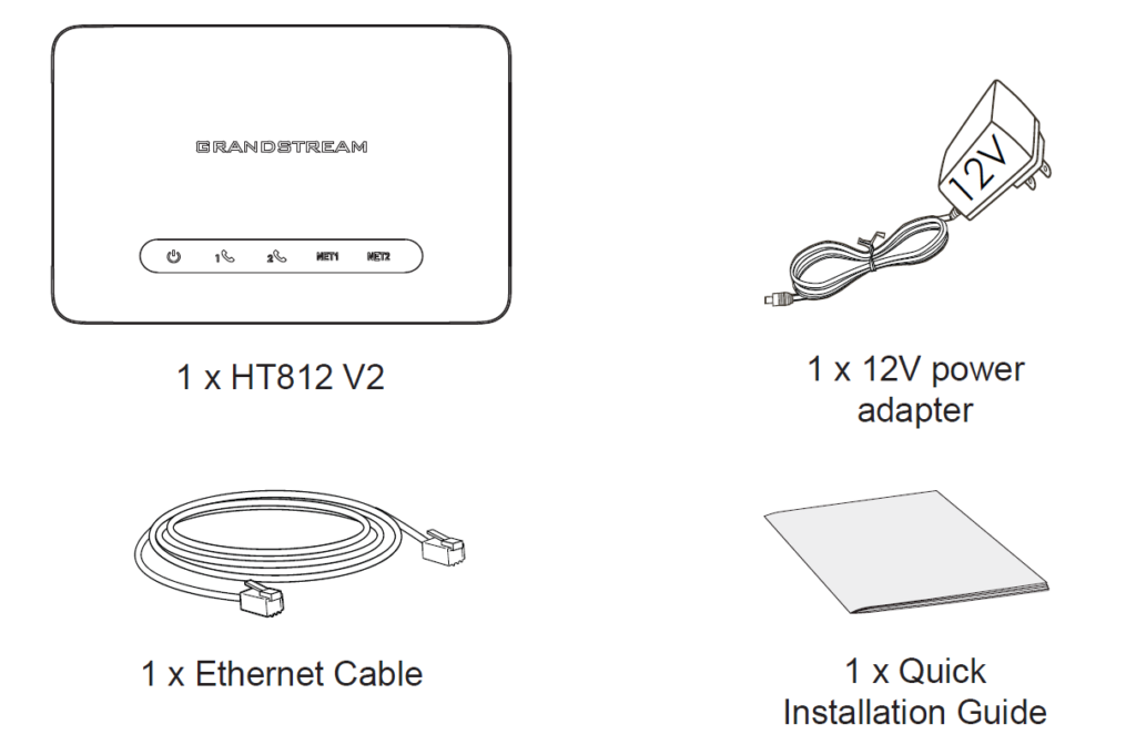
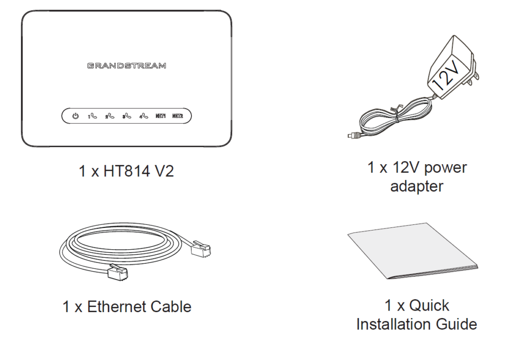

HT81x V2 Ports Description
The following figure describes the different ports on the back panel of the HT81x V2.

Port | Description |
 | Power socket. Used to power HT812 V2 (12V) |
 | NET1 port. Can be configured as LAN or WAN port on the HT812 V2. By default, it is considered a WAN port. |
 | NET2 port. Can be configured as LAN or WAN port on the HT812 V2. By default, it is considered a LAN port. |
 | FXS ports to connect analog phones / fax machines to HT812 V2 using RJ11 telephone cable. |
 | Factory reset button. Press for 7 seconds to reset to factory default settings. |

Port | Description |
| | Power socket. Used to power HT814 V2 (12V) |
| | NET1 port. Can be configured as LAN or WAN port on the HT814 V2. By default, it is considered a WAN port. |
| | NET2 port. Can be configured as LAN or WAN port on the HT814 V2. By default, it is considered a LAN port. |
 | FXS ports to connect analog phones / fax machines to HT814 V2 using RJ11 telephone cable. |
| | Factory reset button. Press for 7 seconds to reset to factory default settings. |

Port | Description |
| | Power socket. Used to power HT818 V2 (12V) |
| | NET1 port. Can be configured as LAN or WAN port on the HT818 V2. By default, it is considered a WAN port. |
| | NET2 port. Can be configured as LAN or WAN port on the HT818 V2. By default, it is considered a LAN port. |
 | FXS ports to connect analog phones / fax machines to HT818 V2 using RJ11 telephone cable. |
| | Factory reset button. Press for 7 seconds to reset to factory default settings. |
Connecting the HT81x V2
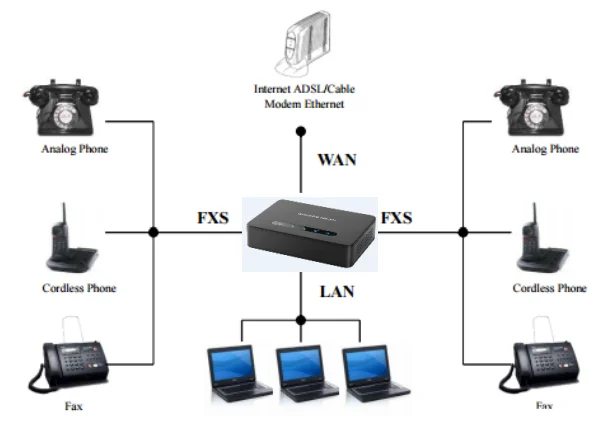
The HT81x V2 can be connected via NET1 port or NET2 port, by default, NET1 is WAN (DHCP Client) and NET2 is LAN (DHCP Server).
Scenario 1: Connecting the HT81x V2 Using NET1 port
When connecting HT81x V2 using the NET1 port, it will act as a simple DHCP Client:
- Insert a standard RJ11 telephone cable into an FXS port and connect the other end of the telephone cable to a standard touch-tone analog telephone.
- Connect the NET1 port of the HT81x V2 to a router, switch or modem using an Ethernet cable.
- Insert the power adapter into the HT81x V2 and connect it to a wall outlet (make sure to respect the technical specifications of the power adapter used).
- The Power, NET1 and FXS LEDs will be solidly lit when the HT81x V2 is ready for use.
Scenario 2: Connecting the HT81x V2 Using NET2 port
When connecting the HT81x V2 using the NET2 port, it will act as a DHCP Server:
- Insert a standard RJ11 telephone cable into an FXS port and connect the other end of the telephone cable to a standard touch-tone analog telephone.
- Connect a computer or switch to the NET2 port of the HT81x V2 using an Ethernet Cable.
- Insert the power adapter into the HT81x V2 and connect it to a wall outlet and make sure to respect the technical specifications of the power adapter used.
- The Power, NET2 and FXS LEDs will be solidly lit when the HT81x V2 is ready for use.
HT81x V2 LEDs Pattern
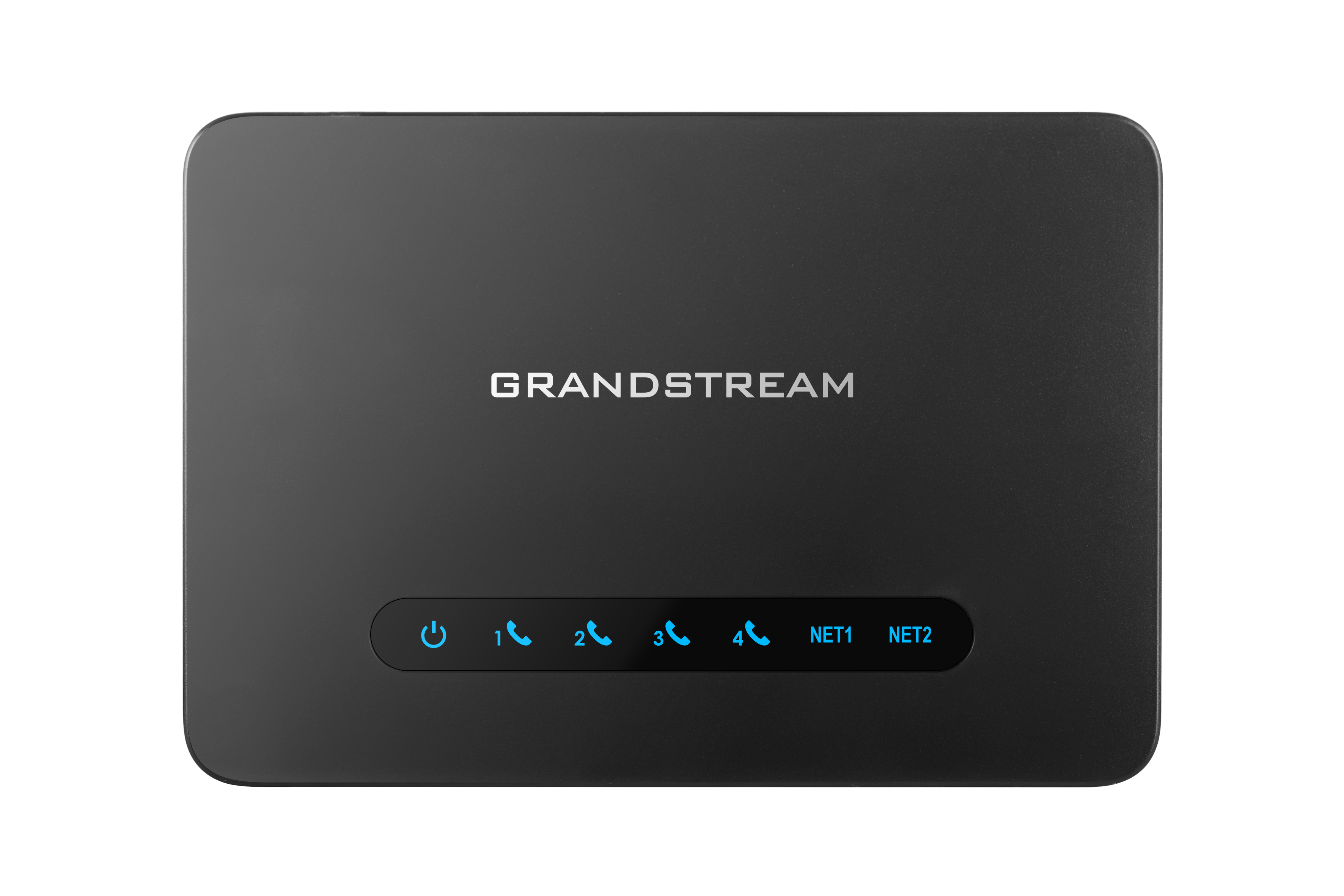
There are four (4) LED types that help you manage the status of your HT81x V2.

LED Lights | Status |
Power LED | The Power LED lights up when The HT812 V2 is powered on and it flashes when the HT812 V2 is booting up |
NET1 LED | The NET1 LED lights up when The HT812 V2 is connected to your network through the NET1 port. |
NET2 LED | The NET2 LED lights up when The HT812 V2 is connected to your network through the NET2 port. |
Phone LED 1-2 | The phone LEDs indicate status of the respective FXS port-phone on the back panel
|
HT812 V2 LEDs Pattern Description
LED Lights | Status |
Power LED | The Power LED lights up when The HT814 V2 is powered on and it flashes when the HT814 V2 is booting up |
NET1 LED | The NET1 LED lights up when The HT814 V2 is connected to your network through the NET1 port. |
NET2 LED | The NET2 LED lights up when The HT814 V2 is connected to your network through the NET2 port. |
Phone LED 1-4 | The phone LEDs indicate status of the respective FXS port-phone on the back panel
|

LED Lights | Status |
Power LED | The Power LED lights up when The HT818 V2 is powered on and it flashes when the HT818 V2 is booting up |
NET1 LED | The NET1 LED lights up when The HT818 V2 is connected to your network through the NET1 port. |
NET2 LED | The NET2 LED lights up when The HT818 V2 is connected to your network through the NET2 port. |
Phone LED 1- 8 | The phone LEDs indicate status of the respective FXS port-phone on the back panel
|
CONFIGURATION GUIDE
The HT81x V2 can be configured in one of two ways:
- The IVR voice prompt menu.
- The Web GUI is embedded on the HT81x V2 using the PC’s web browser.
Obtain HT81x V2 IP Address via Connected Analog Phone
HT81x V2 are by default configured to obtain the IP address from the DHCP server where the unit is located. To know which IP address is assigned to your HT81x V2, you should access the “Interactive Voice Response Menu” of your adapter via the connected phone and check its IP address mode.
Please refer to the steps below to access the interactive voice response menu:
- Use a telephone connected to the phone ports (FXS) of your HT81x V2.
- Press *** (press the star key three times) to access the IVR menu and wait until you hear “Enter the menu option “.
- Press 02 and the current IP address will be announced.
Understanding HT81x V2 Interactive Voice Prompt Response Menu
The HT81x V2 have a built-in voice prompt menu for simple device configuration which lists actions, commands, menu choices, and descriptions. The IVR menu works with any phone connected to the HT81x V2. Pick up the handset and dial “***” to use the IVR menu.
Menu | Voice Prompt | Options |
Main Menu | “Enter a Menu Option” | Press “*” for the next menu option Press “#” to return to the main menu Enter 01-05, 07,10, 12-17, 20, 47 or 99 menu options |
01 | “DHCP Mode”, “Static IP Mode” “PPPoE Mode“ | Press “9” to toggle the selection If using “Static IP Mode”, configure the IP address information using menus 02 to 05. If using “Dynamic IP Mode”, all IP address information comes from the DHCP server automatically after reboot. If using “PPPoE Mode”, configure PPPoE Username and Password from web GUI to get IP from your ISP. |
02 | “IP Address “ + IP address | The current WAN IP address is announced If using “Static IP Mode”, enter 12-digit new IP address. You need to reboot your HT812 V2/HT814 V2/HT818 V2 for the new IP address to take Effect. |
03 | “Subnet “ + IP address | Same as menu 02 |
04 | “Gateway “ + IP address | Same as menu 02 |
05 | “DNS Server “ + IP address | Same as menu 02 |
07 | Preferred Vocoder | Press “9” to move to the next selection in the list:
PCM U / PCM A iLBC G-726 G-723 G-729 OPUS G722
|
10 | “MAC Address” | Announces the MAC address of the unit.
Note: The device has two MAC addresses. One for the WAN port and one for the LAN port. The device MAC address announced is the address of LAN port. |
13 | Firmware Server IP Address | Announces current Firmware Server IP address. Enter 12-digit new IP address. |
14 | Configuration Server IP Address | Announces current Config Server Path IP address. Enter 12-digit new IP address. |
15 | Upgrade Protocol | Upgrade protocol for firmware and configuration update. Press “9” to toggle between TFTP/HTTP/HTTP /FTP/FTPS |
16 | Firmware Version | Announces Firmware version information. |
17 | Firmware Upgrade | Firmware upgrade mode. Press “9” to toggle among the following three options: Always check Check when pre/suffix changes Never upgrade |
20 | Certificate Type | Annouces certificate information. |
47 | “Direct IP Calling” | Enter the target IP address to make a direct IP call, after dial tone. |
86 | Voice Mail | Access to your voice mails messages. |
99 | “RESET” | Press “9” to reboot the device Enter MAC address to restore factory default setting (See Restore Factory Default Setting section) |
“Invalid Entry” | Automatically returns to main menu | |
“Device not registered” | This prompt will be played immediately after off hook If the device is not registered and the option “Outgoing Call without Registration” is in NO |
Voice Prompt Menu
Five success tips when using the voice prompt
- “*” shifts down to the next menu option and “#” returns to the main menu
- “9” functions as the ENTER key in many cases to confirm or toggle an option.
- All entered digit sequences have known lengths – 2 digits for the menu option and 12 digits for the IP address. For IP address, add 0 before the digits if the digits are less than 3 (i.e. – 192.168.0.26 should be keyed in like 192168000026. No decimal is needed).
- Key entry cannot be deleted but the phone may prompt an error once it is detected.
- Dial *98 to announce the extension number of the port.
Configuration via Web Browser
The HT81x V2 embedded Web server responds to HTTP GET/POST requests. Embedded HTML pages allow a user to configure the HT81x V2 through a web browser such as Google Chrome, Mozilla Firefox, and Microsoft’s IE.
- Microsoft Internet Explorer: version 10 or higher.
- Google Chrome: version 58.0.3 or higher.
- Mozilla Firefox: version 53.0.2 or higher.
- Safari: version 5.1.4 or higher.
- Opera: version 44.0.2 or higher.
Accessing the Web UI
The HT81x V2 can be connected via NET1 port or NET2 port, by default, NET1 is WAN (DHCP Client) and NET2 is LAN (DHCP Server).
- Via NET1 port
For the initial setup, the Web access is by default enabled when the device is using a private IP and disabled when using a public IP, and you cannot access the Web UI of your HT81x V2 until it’s enabled, the following steps will show you how to enable it via IVR.
- Power your HT81x V2 using a PSU with the right specifications.
- Connect your analog phone to the phone ports (FXS) of your HT81x V2.
- Press *** (press the star key three times) to access the IVR menu and wait until you hear “Enter the menu option “.
- Press 12, and the IVR menu will announce that the web access is disabled, press 9 to enable it.
- Reboot your HT81x V2 to apply the new settings.
Please refer to the steps below if your HT81x V2 is connected via the NET1 port:
- You may check your HT81x V2 IP address using the IVR on the connected phone.
Please see Obtain the HT81x V2 IP address via the connected analog phone
- Open the web browser on your computer.
- Enter the HT81x V2’s IP address in the address bar of the browser.
- Enter the administrator’s password to access the Web Configuration Menu.
- Via NET2 port
Please refer to the steps below if your HT81x V2 is connected via NET2 port:
- Power your HT81x V2 using PSU with the right specifications.
- Connect your computer or switch directly to your HT81x V2 NET2 port.
- Open the web browser on your computer.
- Enter the default NET2 IP address (192.168.2.1) in the address bar of the browser.
- Enter the administrator’s password to access the Web Configuration Menu.
- Make sure to reboot your device after changing your settings to apply the new configuration.
Web UI Access Level Management
There are three access level for the login page:
User Level | User | Password | Web Pages Allowed |
End User Level | user | 123 | View all pages but can only modify basic settings |
Administrator Level | admin | random password located at the back of the unit | Browse all pages and modify all settings |
Viewer Level | viewer | viewer | View all pages but no changes allowed. |
Saving the Configuration Changes
After modifying any configuration parameters, users can save the changes by clicking on the Save button. Once the configuration is saved, an Apply button will appear at the top of the page to allow users to apply the changes.
Users can also directly click on the Save and Apply button for the configuration changes to be saved and applied.
Changing Admin Level Password
- Access your HT81x V2 web UI by entering its IP address in your favorite browser.
- Enter your admin password (default is the random password located at the back of the unit).
- Press Login to access your settings.
- Go to System Settings 🡪 Security Settings 🡪 User Info Management and enter the new admin password.
- Confirm the new admin password.
- Press Apply at the bottom of the page to save your new settings.

Changing User Level Password
- Access your HT81x V2 web UI by entering its IP address in your favorite browser.
- Enter your admin password (default is the random password located at the back of the unit).
- Press Login to access your settings.
- Go to System Settings 🡪 Security Settings 🡪 User Info Management and enter the new end-user password.
- Confirm the new end-user password.
- Press Apply at the bottom of the page to save your new settings.

Changing Viewer Password
- Access your HT81x V2 web UI by entering its IP address in your favorite browser.
- Enter your admin password (default is the random password located at the back of the unit).
- Press Login to access your settings.
- Go to System Settings → Security Settings → User Info Management and enter the new viewer password.
- Confirm the new viewer password.
- Press Apply at the bottom of the page to save your new settings.

Changing HTTP Web Port
- Access your HT81x V2 web UI by entering its IP address in your favorite browser.
- Enter your admin password (default is the random password located at the back of the unit).
- Press Login to access your settings.
- Go to System Settings 🡪 Security Settings🡪 Web/SSH Access.
- Make sure that the Web Access Mode is set to HTTP.
- Change the current port to your desired/new HTTP port. Ports accepted are in the range [1-65535].
- Press Apply at the bottom of the page to save your new settings

Web Configuration Pages Definitions
This section describes the options in the HT81x V2 Web UI. As mentioned, you can log in as an administrator or an end user.
Status Page Definitions
System Info
Product Model | Displays the Product model: HT812V2, HT814V2 or HT818V2. |
Serial Number | Displays the device’s serial number |
Hardware Version | |
Hardware Version | Displays the hardware version |
Part Number | Displays the part number. |
Software Version | |
Software Version |
|
Vendor Default Config Version | |
Project | Displays the unique project ID of the custom configuration file. |
Vendor Default Config Version | Displays the version of the custom configuration file. |
Operation State | |
Software Status | Displays whether the software is running correctly on the device |
Mem | Displays the memory usage. |
System Up Time | Displays the duration of the system up time. |
System Current Time | Displays the HT8xx current time |
CPU Load | Displays the processor load |
Provision | Displays the last status of provisioning |
System Info | Downloads a diagnostic system information file from the device, containing technical details such as firmware version, uptime, system status, and other runtime information useful for troubleshooting. |
Core Dump | |
Core Dump | Displays the core dump file when available and which could be downloaded for troubleshooting purpose. |
Network Status
MAC Address | Displays the device’s MAC address, this will include the WAN and LAN mac addresses, for the NET1 and NET2 ports. |
IPv4 Address | Displays the assigned IPv4 address |
IPv6 Address | Displays the assigned IPv6 address |
VPN IPv4 Address | Displays the connected VPN IPv4 address, if available. |
VPN IPv6 Address | Displays the connected VPN IPv4 address, if available. |
Network Cable Status | Displays the status of the NET1 and NET2 ports, it is shown as UP if connected, and DOWN if disconnected |
PPPoE Link Up | Indicates active connectivity between the gateway and the network provider through PPPoE |
NAT | Displays the type of NAT used |
Certificate Type | Displays the certificate type |
Port Status
Port Status | |
Port | Displays the type of analog port : FXS1, FXS2, FXS3….FXS8 |
Hook | Shows the status of the port, On Hook, Off Hook, Not connected… |
User ID | Displays the SIP user ID registred on the port. |
Registration | Displays wether the port is registered or not. |
Sip Port | Displays the SIP Destination port used by the analog interface. |
Port Options | |
Port | Displays the FXS ports. |
DND | Displays whether the connected analog phone is on DND mode or not. |
Forward | Indicates the forwarding number. |
Busy Forward | Indicates the busy forwarding number. |
Delayed Forward | Indicates the delayed forwarding number. |
CID | Indicates the Caller ID. |
Call Waiting | Indicates if Call waiting is enabled. |
SRTP | Indicates if Secured RTP is enabled. |
System Settings Page Definitions
Basic Settings
Enable Voice Prompt | The voice prompt is disabled if set to Yes. |
Enable Direct IP Call | The direct IP calling is disabled if set to No. Default value is “Yes”. |
Blocklist For Incoming Calls | Blocks calls from specific numbers. Use “,” to separate numbers. |
Lock Keypad Update | The configuration update via keypad is disabled if set to Yes. Default value is “No” |
Play Busy Tone When Account is unregistered | If set to Yes, busy tone will be played when user goes offhook from an unregistered account. |
Hunting Group Registration Mode | The Hunting Group Registration Mode determines how SIP registration works for a group of FXS ports.
|
DHCP Option 17 Enterprise Number | Fill in the DHCP Option 17 enterprise number. Range: 0-65535. Default is 3561. |
ATA Setting | |
STUN Server | The IP address or domain name of the STUN server. Only non-symmetric NAT routers work with STUN. |
Keep-Alive Interval | Specifies how often the device sends a blank UDP packet to the SIP server in order to keep the “ping hole” on the NAT router to open. Default is 20 seconds. Range is 10-160 seconds. |
Use STUN to detect network connectivity | Use STUN keep-alive to detect WAN side network problems. |
Time and Language
Time Zone | |
NTP Server | This parameter sets the IP address of the NTP server. The device will obtain the date and time from the server. |
Secondary NTP Server | This feature allows users to configure the secondary NTP server, by default, no secondary NTP Server is configured. |
Allow DHCP Option 42 to override NTP server | If DHCP Option 42 is enabled, the NTP server can be changed. Enabled by default. |
Time Zone | Selects the time zone where the phone is located and control the date/time display. |
Self-Defined Time Zone | Allows users to define their own time zone when time zone is set to “Using self-defined Time Zone”
M4.1.0,M11.1.0 The 1st number indicates Month: 1,2,3.., 12 (for Jan, Feb, .., Dec) The 2nd number indicates the nth iteration of the weekday: (1st Sunday, 3rd Tuesday…) The 3rd number indicates weekday: 0,1,2,..,6 (for Sun, Mon, Tues, … ,Sat) Therefore, this example is the DST which starts from the Second Sunday of March to the 1st Sunday of November. |
Allow DHCP server to set Time Zone | Allows the local server’s DHCP option 2 to override the phone’s time zone setting. Default is “Yes”. |
Local Time | Allows the HT8xx device to get information about the time and date from the PC |
Language | |
IVR Language | Selects IVR voice prompt language type, the supported languages are: English, Chinese, Russian, Spanish. |
Ringtone
System Ring Cadence | Cadence on+off value range (0, 16000) milliseconds |
Prompt Tone Access Code | The key pattern to get Prompt Tone. Maximum 20 digits. No default value provided |
CPT Settings:
| Using these settings, users can configure tone frequencies and cadence according to their preferences. By default, they are set to North American frequencies.
|
Security Settings
Security Settings → Web/SSH Access | |
Basic Settings | |
Web Access Mode | Selects the web page access protocol. The available options are: HTTP, HTTPS, Disabled. The default settings is “HTTPS”. |
HTTP Web Port | Defines the HTTP Web Port. The default setting is “80”. The valid range is 1-65533. |
HTTPS Web Port | Defines the HTTPS Web Port. |
Web Session Timeout | Defines the web session timeout in minutes. |
Web Access Attempt Limit | Defines the number of failed web login attempts allowed before web access is locked. The default setting is “5”, the valid range is 1-10. |
Web Lockout Duration | Defines the duration for which web access is locked in minutes. |
Enable User Level Web Access | Enables or disables user-level web access. |
Enable Viewer Level Web Access | Enables or disables viewer-level web access. |
SSH | |
Enable SSH | Enables or disables SSH access to the phone. |
SSH Port | Defines the SSH port. This port cannot be the same as the Telnet Port. |
SSH Idle Timeout | Configures SSH session Timeout in seconds. |
Enable Telnet | Enables or disables Telnet access. Disabled by default. |
Telnet Port | Defines the Telnet port. This port cannot be the same as the SSH Port. |
Telnet Idle Timeout | Configures Telnet session Timeout in seconds. |
Security Controls for SSH/Telent Access | Specifies security measures and controls that apply to the SSH/Telnet protocol to ensure secure and authorized access to the device, the following options are supported
The default setting is “Allow any user to set any PValue” |
Enable Web/SSH Access | Enables or Disables the Web and SSH access through the WAN port. The available options are the following:
The default setting is “Yes”. |
Access Control | |
Allow List for WAN Side | If Enable Web/SSH Access is set to Yes or Auto. Users can configure the white List for WAN Side to be used for remote management. Multiple IPs are supported and need to be separated by space. Example:192.168.5.222 192.168.5.223 192.168.7.0/24 Note: If both blocklist and allowlist are not empty, the blocklist is processed first, followed by the allow list. |
Block List for WAN Side | If Enable Web/SSH Access is set to Yes or Auto. Users can configure the black List for WAN Side to ban WAN side web access. Multiple IPs are supported and need to be separated by space. Example: 192.168.5.222 192.168.5.223 192.168.7.0/24 Note: If both blocklist and allowlist are not empty, the blocklist is processed first, followed by the allow list. |
Security Settings → User Info Management | |
Password Rules | |
Enable strict password rules | Enable or disables strict password rules. |
Minimum password length | Defines the Minimum password length, Range: 4-30, default is 8. |
Required number of character classes | Sets the minimum number of character classes that a password should contain, composed of allowed combinations of different character classes; Range: 0-4, default is 3. |
Allowed Character classes | Defines the Allowed Character classes, which are: Lower case, Upper case, Numbers, Special characters. |
Password | |
New Admin Password | Defines the new admin password, Must contain 4-30 characters, When strict password rules are enabled, the password needs to comply with the settings in the password rules; Do not display password for security reasons. |
Confirm Admin Password | Confirms the entered admin password. |
New User Password | Defines the new user password, Must contain 4-30 characters, When strict password rules are enabled, the password needs to comply with the settings in the password rules; Do not display password for security reasons. |
Confirm User Password | Confirms the entered user password. |
New Viewer Password | Defines the new viewer password, Must contain 4-30 characters, When strict password rules are enabled, the password needs to comply with the settings in the password rules; Do not display password for security reasons. |
Confirm Viewer Password | Confirms the entered viewer password. |
Security Settings → Client Certificate | |
SIP TLS | |
Enable/Disable Weak Cipher Suites | Controls whether the device allows the use of weakened or deprecated TLS cipher suites. You can either allow weak TLS ciphers or selectively disable specific weak encryption, authentication, or key-exchange algorithm. Disabling weak cipher suites is recommended to improve security and comply with modern TLS standards.
By default, it is set to “Disable All Of The Above Weak TLS Ciphers Suites” |
SIP TLS Certificate | Specifies SSL certificate used for SIP over TLS is in X.509 format. The HT8xx has built-in private key and SSL certificate. The maximum supported length is 8192. |
SIP TLS Private Key | Specifies TLS private key used for SIP over TLS is in X.509 format. The maximum supported length is 4069. |
SIP TLS Private Key Password | Specifies SSL Private key password used for SIP Transport in TLS/TCP. |
TLS Version | |
Minimum TLS Version | This feature allows customer to choose desired Minimum TLS Version.
The default setting is “TLS 1.2”. |
Maximum TLS Version | This feature allows customer to choose desired Maximum TLS Version.
The default setting is “Unlimited”. |
Custom Certificate | |
Custom Certificate | Allows users to update to the device their own certificate signed by a custom CA certificate to manage client authentication. |
Security Settings → Trusted CA Certificates | |
Load CA Certificates | This feature allows user to specify which certificate to trust when performing server authentication. |
| These trusted CA certificates will be used for the authentication server TLS certificate |
Security Settings → SCEP | |
Basic Settings | |
Enable SCEP | Enables or disables the SCEP feature. Disabled by default. |
SCEP Server URL | Defines the SCEP server URL (CA or RA). The URL must include the protocol prefix. Currently, only HTTP is supported. |
CA FingerPrint Infomation | Defines the fingerprint of the CA certificate. |
Challenge Password | Defines the temporary challenge password included in the Certificate Signing Request (CSR) when requesting a new certificate. |
Local configuration | |
Local Public and Private Key Length | Specifies the length of the local public and private keys. The default setting is “3072 bit”. |
The Name of Certificate Applicant | Defines the name of the certificate applicant. This field is required. |
The Country of Certificate Applicant Located | Selects the country where the certificate applicant is located. |
The State of Certificate Applicant Located | Defines the state or province where the certificate applicant is located. |
The Locality of Certificate Applicant Located | Defines the locality of where the certificate applicant is located. |
The Organization of Certificate Applicant Located | Defines the location of the organization to which the certificate applicant belongs. |
The Organization Unit of Certificate Applicant | Defines the organization unit of the certificate applicant, such as a company, government agency, or nonprofit organization. |
HTTP Authentication | |
CID | Configures the HTTP authentication user ID used to access the CA server. |
Password | Configures the HTTP authentication password used to access the CA server. |
Certificates and Updates | |
CA Certificates | Displays the CA certificate obtained through SCEP. Note: Copy the displayed CA certificate and import it into the trusted CA certificate store on the CA server. |
Client Certificate Alternative Name | Configures additional identifiers for the client certificate. These values are added as Subject Alternative Name (SAN) entries on the server and allow the device to be identified using multiple aliases. In the configuration file, different aliases are separated by semicolons (;). The available options are:
The default setting is “$MAC.local”. |
Update Interval before Certificate Expiration | Defines the number of days (1–30) before expiration to trigger certificate renewal. The system attempts renewal when the remaining validity is less than the defined interval. Pressing Update Now starts the renewal manually. |
Scope of Use | Configures where the CA and client certificates are applied. Certificates for selected modules are managed automatically via SCEP, without manual upload or renewal. The available options are: Custom Certificate, 802.1X, OpenVPN, TR069. |
TR069
Enable TR-069 | Sets the phone adapter system to enable the “CPE WAN Management Protocol” (TR-069). The default setting is Yes. |
ACS URL | Specifies URL of TR-069 Auto Configuration Servers (e.g., http://acs.mycompany.com), or IP address. Default setting is: “https://acs.gdms.cloud” |
ACS Username | Enter username to authenticate to ACS. Maximum allowed length is 64. |
ACS Password | Enter password to authenticate to ACS. Maximum allowed length is 64. |
Periodic Inform Enable | Sends periodic inform packets to ACS. Default is Yes. |
Periodic Inform Interval | Sets frequency that the inform packets will be sent out to ACS. Default is 86400 seconds. |
Connection Request Username | Enters username for ACS to connect to the HT81x V2. |
Connection Request Password | Enters password for ACS to connect to the HT81x V2. |
Connection Request Port | Configures the TR-069 connection request port. The value range is 0 to 65535.Default is 7547 |
CPE SSL Certificate | Configures the Cert File for the phone adapter to connect to the ACS via SSL. Maximum allowed length is 8192 |
CPE SSL Private Key | Specifies the Cert Key for the phone adapter to connect to the ACS via SSL. Maximum allowed length is 2048 |
RADIUS Settings
Enable RADIUS Web Access Control | Selects whether to enable RADIUS web access control. Default is no |
Action upon Radius Auth Server Error | Select the RADIUS authentication server error handling method,the user can choose between: Reject Access, or Authentificate locally, the default is “local verification” |
Enable Bypass Locked State | Once enabled, RADIUS accounts can bypass the webUI locked state caused by local accounts. |
RADIUS Auth Protocol | Configures RADIUS authentication protocol |
RADIUS Auth Server Address | Configures RADIUS authentication server address |
RADIUS Auth Server Port | Configure RADIUS authentication server port |
RADIUS Shared Secret | Configures the shared secret key |
RADIUS VSA Vendor ID | Configure the RADIUS VSA provider ID to match the RADIUS server’s configuration. The default value for Grandstream Networks Inc is 42397 |
RADIUS VSA Access Level Attribute | Configure the RADIUS VSA access level attributes to match the configuration of the RADIUS server. Incorrect settings will cause Radius authentication to fail. |
E911/HELD
E911 | |
Enable E911 | Enable Enhanced 911 call. Default is disabled |
E911 Emergency Numbers | A user can configure multiple emergency numbers separated with the delimiter symbol “;”. Default is 911. |
Geolocation-Routing Header | When enabled, the device includes a “Geolocation-Routing: Yes” header in the SIP INVITE for E911 calls to support location-based emergency call routing. |
Priority Header | If “Yes”, E.911 INVITE message includes the “Priority” header with the value “emergency”. Default is “No”. |
Geolocation Header Format | Selects the format used for the SIP Geolocation header when sending emergency calls:
Set to “Legacy” by default. |
HELD | |
HELD Protocol | Configure HELD transfer protocol. HTTP or HTTPS. Default is HTTP. |
HELD Synchronization Interval | The valid synchronization interval is between 30 to 1440 minutes. The synchronization is off when the interval is 0. Default is 0. |
HELD Location Types | Configure “locationType” element in the location request. “geodetic”, “civic” and “location URI”. |
HELD Use LLDP Information | If set to “Yes”, LLDP protocol will be used to gather information about the HT device including information about the ChassisID and PortID. Otherwise, the system defaults to using the MAC address of the gateway and phone. Default setting is “No”. |
HELD NAI | If ‘Yes’ is selected, the Network Access Identifier (NAI) is included as the device identity in location requests sent to the Location Information Server (LIS). Default is “No”. |
HELD Identity 1-10 | The HELD Identity refers to Hierarchical Mobile IPv6 (HMIPv6) Enhanced Location-based Discovery (HELD) protocol. This protocol is utilized to determine the location of a mobile device when making an emergency call, such as a 911 call, over an IP-based network. |
HELD Identity 1-10 Value | Defines the HELD Identity value. Maximum allowed length is 64 |
Location Server | |
Location Server | Configures the location server (LIS) address. |
Location Server Username | Configures Location Server (LIS) username. Maximum allowed length is 64. |
Location Server Password | Configures Location Server (LIS) password. Maximum allowed length is 64. |
Secondary Location Server | Configures secondary location server (LIS) address. |
Secondary Location Server Username | Configures secondary location server (LIS) username. Maximum allowed length is 64. |
Secondary Location Server Password | Configures secondary location server (LIS) password. Maximum allowed length is 64. |
Network Settings Page Definitions
Ethernet Settings
Ethernet Settings | |
General Settings | |
Internet Protocol | Selects one of the following IP protocol modes:
Note: Make sure to reboot the HT81x V2 unit for the changes to take effect. |
IPv4 | |
IPv4 address type | Allows users to configure the appropriate network settings on the HT81x V2 to obtain IPv4 address. Users could select DHCP, Static IP or PPPoE. By default, it is set to DHCP. |
Host Name (Option 12) | Specifies the name of the client. The name may or may not be qualified with the local domain name. This field is optional but may be required by ISP. |
DHCP Domain | Allows user to configure DHCP domain name. This option specifies the domain name that the client should use when resolving hostnames via the Domain Name System. This field is optional. |
Vendor Class ID (Option 60) | Exchanges vendor class ID by clients and servers to convey particular configuration or other identification information about a client. Default is HT8XXV2. |
PPPoE account ID | Defines the PPPoE username. Necessary if ISP requires you to use a PPPoE (Point to Point Protocol over Ethernet) connection. |
PPPoE password | Specifies the PPPoE account password. |
PPPoE Service Name | Defines PPPoE service name. If your ISP uses a service name for the PPPoE connection, enter the service name here. This field is optional. |
Preferred DNS server 1-4 | Specifies preferred DNS server to use when DHCP or PPPoE are set. |
IPv6 | |
IPv6 address type | Configures the IPv6 address of the phone:
|
Static address type |
|
Static IPv6 Address | When using fully static type IPv6, enter a static IPv6 address. |
IPv6 Prefix Length | Enter the static IPv6 address prefix length. |
DNS Server 1 | Enter DNS server 1 address. |
DNS Server 2 | Enter DNS server 2 addres. |
Preferred DNS Server | Enter preferred DNS server address. |
802.1x Settings | |
802.1x Mode | Allow users to enable/disable 802.1X Mode. The modes available are:
Disabled by default. |
802.1x Identity | Enter 802.1X identity information. |
802.1x Password | Enter 802.1X MD5 password. |
802.1x CA Certificate | Paste down the 802.1X certificate .pem file. |
802.1x Client Certificate | Paste down the Client.pem certificate file containing certificate and key. Maximum allowed length is 8192. |
SNMP Settings
Enable SNMP | Enables the Simple Network Management Protocol. |
SNMP Version | Choose between (Version 1, Version 2c, or Version 3). |
SNMP Port | Listening Port of SNMP. Valid range is 161 or 1025-65535. (Default is 161). |
SNMP Trap IP Address | IP address of trap destination. Up to 3 trap destinations are supported. Users should enter the IP addresses separated with comma (,). |
SNMP Trap Port | Port of Trap destination. Valid range is 162 or 1025-65535. (Default 162). |
SNMP Trap Version | Choose between (Version 1, Version 2c, or Version 3). |
SNMP Trap Interval | Time interval in minutes between traps. (Default is 5). |
SNMPv1/v2c Community | Name of SNMPv1/v2c community. |
SNMPv1/v2c Trap Community | Name of SNMPv1/v2c trap community. |
SNMPv3 User Name | Username for SNMPv3. |
SNMPv3 Security Level | noAuthUser: Users with security level noAuthnoPriv and context name as noAuth. authUser: Users with security level authNoPriv and context name as auth. privUser: Users with security level authPriv and context name as priv. |
SNMPv3 Authentication Protocol | Select the Authentication Protocol: “None” or “MD5” or “SHA.” |
SNMPv3 Privacy Protocol | Select the Privacy Protocol: “None” or “AES/AES128” or “DES”. |
SNMPv3 Authentication Key | Enter the Authentication Key. |
SNMPv3 Privacy Key | Enter the Privacy Key. |
SNMPv3 Trap User Name | Username for SNMPv3 Trap. |
SNMPv3 Trap Security Level | noAuthUser: Users with security level noAuthnoPriv and context name as noAuth. authUser: Users with security level authNoPriv and context name as auth. privUser: Users with security level authPriv and context name as priv. |
SNMPv3 Trap Authentication Protocol | Select the Authentication Protocol: “None” or “MD5” or “SHA”. |
SNMPv3 Trap Privacy Protocol | Select the Privacy Protocol: “None” or “AES/AES128” or “DES”. |
SNMPv3 Trap Authentication Key | Enter the Trap Authentication Key. |
SNMPv3 Trap Privacy Key | Enter the Trap Privacy Key. |
MIB | Downloads the MIB file, containg the Object identifiers. |
DDNS Settings
Enable DDNS | Enable DDNS function. Disabled by default. |
DDNS Server | Select DDNS server used, options are:
|
DDNS Username | Sets the username of the DDNS server. |
DDNS Password | Sets the password of the DDNS server. |
DDNS Hostname | Sets the domain name of the DDNS server. |
DDNS Hash | Sets the hash value of the DDNS server. |
LAN Settings
General Settings | |
Device Mode | Controls whether the device is working in NAT Router, Bridge, or WAN Only mode.
The default mode is NAT Router. Save the setting and reboot before configuring the HT81x V2. |
Enable UPnP support | When set to Yes, the HT81x V2 acts as a UPnP gateway for your UPnP-enabled applications. UPnP = Universal Plug and Play. The default is No. |
Uplink bandwidth | Specifies the maximum uplink bandwidth permitted by the device. This function is disabled by default. The total bandwidth can be set as 128K, 256K, 512K, 1M, 2M, 3M, 4M, 5M, 10M, or 15 M. The primary function of this setting is to limit the uplink bandwidth for the device’s internal system, signaling, and NATed traffic. Example: When 512k is configured, there will be at least 512kbps limited for internal system, signaling, and NATed traffic. Note: Voice or RTP stream will never be limited. |
Downlink bandwidth | Specifies the maximum downlink bandwidth permitted by the device. This function is disabled by default. The total bandwidth can be set as 128K, 256K, 512K, 1M, 2M, 3M, 4M, 5M, 10M, or 15 M. The primary function of this setting is to limit the download bandwidth for the device’s internal system, signaling, and NATed traffic. Example: if 128 is configured, there will be at least 128kbps limited for internal system, signaling, and NATed traffic. Note: Voice or RTP stream will never be limited. |
DMZ IP | This function forwards all WAN IP traffic to a specific IP address if no matching port is used by HT81x V2 or in the defined port forwarding. |
NAT maximum ports | Defines the number of ports that can be managed while in NAT router mode. |
NAT TCP timeout | NAT TCP idle timeout in seconds. The connection will be closed after preconfigured, timeout if not refreshed. Range: 0 – 3600 |
NAT UDP timeout | NAT UDP idle timeout in seconds. The connection will be closed after preconfigured, timeout if not refreshed. Range: 0 – 3600, default is 300 |
Reply to ICMP on WAN port | When set to Yes, the HT81x V2 responds to the PING command from other computers but is also made vulnerable to DOS attacks. The default is No. |
Cloned WAN MAC Addr | This allows the user to change/set a specific MAC address on the WAN interface. Note: Set in Hex format. |
LAN Port VLAN Feature Under Bridge Mode | This feature allows users to configure a different VLAN tag and priority value for the second network port when HT81x V2 is configured in bridge mode. The priority value range is 0-7, The VLAN tag range is 0-4094. |
Enable LAN DHCP | When set to Yes, the device will function as a simple router and the LAN port will provide IP addresses to the internal network. Connect the WAN port to ADSL/Cable modem or any other equipment that provides access to the public Internet. The default setting is Yes. |
LAN DHCP Base IP | Base IP Address for a LAN port. The default factory setting is 192.168.2.1. Note: When the device detects WAN IP is conflicting with LAN IP, the LAN base IP address will be changed based on the network mask the effective subnet will be increased by 1. |
LAN DHCP Start IP | The default value is 100. The last segment of IP address is assigned to the HT81x V2 in the LAN Network. |
LAN DHCP End IP | Default value is 199. This parameter allows a user to limit the number of local network devices connected to the internal router. |
LAN Subnet Mask | Sets the LAN subnet mask. |
DHCP IP Lease Time | Default value is 120 hrs. (5 days). The length of time the IP address is assigned to the LAN clients. Value is set in units of hours. |
Port Forwarding | Forwards a matching (TCP/UDP) port to a specific LAN IP address with a specific (TCP/UDP) port. Up to 8 rules are available. |
Management Interface
Management Interface | |
Enable Management Interface | Allows activation of a dedicated interface for remote management and configuration of the device. |
Management Access | defines the allowed methods (protocols) and permissions for remote access and configuration of the device, two options can be selected
|
Enable SNMP Through Management Interface | Allows the activation of SNMP (Simple Network Management Protocol) access exclusively through the dedicated management interface for monitoring and managing the device remotely. |
Enable TR069 Through Management Interface | Allows the activation of TR-069 protocol access exclusively through the dedicated management interface for remote device management and provisioning. |
Enable Syslog Through Management Interface | Allows the activation of syslog communication exclusively through the dedicated management interface for remote logging and monitoring of device events. |
Enable Radius Through Management Interface | Configure routing so that Radius functionality is accessible through management. |
Management Interface IPv4 Address | |
802.1Q/VLAN Tag | Allows the tagging of network packets with VLAN information to segment and prioritize network traffic. |
802.1p priority value | Assigns a priority value to network packets for Quality of Service (QoS) and traffic prioritization purposes. |
IPv4 address type | Configures the address type of the management network port, the options are:
|
IP Address | Configure the IPv4 address of the management network port |
Subnet Mask | Defines the subnet mask |
Default Router | Defines default gateway |
DNS Server 1 | Defines DNS server 1 address |
DNS Server 2 | Defines DNS server 2 address |
OpenVPN® Settings
OpenVPN® Settings | |
Enable OpenVPN® | Enables or disables the OpenVPN® feature. |
OpenVPN® Server Address | Specifies the IP address or FQDN of the primary OpenVPN® server. |
OpenVPN® Port | Configures the port of the primary OpenVPN® server. |
OpenVPN® Server Secondary Address | Specifies the IP address or FQDN of the secondary OpenVPN® server. If the primary OpenVPN® server is unavailable, the device automatically switches to the secondary server to maintain a secure VPN connection. |
OpenVPN® Secondary Port | Configures the port of the secondary OpenVPN® server. |
Randomly Select Server | Enables or disables random server selection. When enabled, OpenVPN randomly selects a configured server when initiating a connection. When disabled, servers are used in the order in which they are configured. |
OpenVPN® Interface type | Specifies the Interface type of OpenVPN®. The available options are: TAP or TUN. |
OpenVPN® Transport | Specifies the Transport Type of OpenVPN®. The available options are: UDP or TCP. |
Enable OpenVPN® LZO Compression | Enable or disables OpenVPN® LZO Compression. |
OpenVPN® Encryption | Select the OpenVPN® Encryption algorithm. The available options are:
The default setting is “BF-CBC 128 bit default key”. |
OpenVPN® Diges | Select the OpenVPN® Digest. Default is SHA1. |
OpenVPN® Username | Configure the OpenVPN® username. |
OpenVPN® Password | Configure the OpenVPN® password. |
OpenVPN® CA | Specifies the OpenVPN® CA. The maximum length is 8192. |
OpenVPN® Certificate | Specifies the OpenVPN® Certificate. The maximum length is 8192. |
OpenVPN® Client Key | Specifies the Client Key. The maximum length is 8192. |
OpenVPN® Client Key Password | Configures the OpenVPN® Client Key Password. The maximum length is 64. |
OpenVPN® TLS Key | Specifies the static TLS key used by TLS-Auth or TLS-Crypt to authenticate or encrypt the OpenVPN control channel. |
OpenVPN® TLS Key Type | Selects how the static TLS key is used to protect the OpenVPN control channel. The available options are:
The default setting is “none”. |
OpenVPN® Additional Options | Defines additional OpenVPN configuration parameters that are appended to the OpenVPN configuration file. Parameters must be separated by semicolons (;). Example: connect-retry 5;tls-client;keepalive 10 60 |
Advanced Settings
Advanced Settings | |
Enable LLDP | Controls the LLDP (Link Layer Discovery Protocol) service. |
LLDP TX Interval | Configures LLDP TX Interval (in seconds). Valid range is 1 to 3600. The Default value is 60. |
Enable CDP | Enables/Disables CDP “Cisco Discovery Protocol”. |
Enable Manual VLAN Configuration | Allows the device to keep the VLAN configuration without applying it. Note: A reboot is required for the setting to take effect. |
Layer 2 QoS 802.1Q/VLAN Tag | Assigns the VLAN Tag of the Layer 2 QoS packets that can be used to identify and distinguish different VLANs. The default setting is 0. The valid range is 0 to 4094. Note: A reboot is required for the setting to take effect. |
Layer 2 QoS 802.1p Priority Value | Configures the Layer 2 QoS 802.1p Priority Value. The 802.1p priority is the user priority defined in the TCI (Tag Control Information) field of the Layer 2 802.1Q header. During network congestion, switches use this value to prioritize packet transmission. The default setting is 0. The valid range is 0 to 7, where 0 represents the lowest priority and 7 represents the highest priority. Note: A reboot is required for the setting to take effect. |
Layer 2 QoS SIP 802.1p | Configures the Layer 2 QoS 802.1p priority for SIP packets. The default setting is 0. The valid range is 0 to 7, where 0 represents the lowest priority and 7 represents the highest priority. Note: A reboot is required for the setting to take effect. |
Layer 2 QoS RTP 802.1p | Configures the Layer 2 QoS 802.1p priority for RTP packets. The default setting is 0. The valid range is 0 to 7, where 0 represents the lowest priority and 7 represents the highest priority. Note: A reboot is required for the setting to take effect. |
Use DNS to detect network connectivity | Use DNS to detect WAN side network issues. |
Use ARP to detect network connectivity | Use ARP to check network connection. |
HTTP/HTTPS User-Agent | Configures the User-Agent for HTTP/HTTPS request. |
Maximum Transmission Unit (MTU) | Configures the network Maximum Transmission Unit (MTU) in bytes, which defines the largest packet size that can be transmitted. The default is 1500 bytes, with a valid range of 576–1500 bytes. |
Firewall settings | |
Black List for WAN Side Port | Ports on the blocklist will be disabled on the device. |
Proxy | |
HTTP Proxy | Specifies the HTTP proxy URL that the phone uses to send HTTP traffic. The proxy server acts as an intermediary, routing packets from the phone to their destination. |
HTTPS Proxy | Specifies the HTTPS proxy URL that the phone uses to send traffic. The proxy server acts as an intermediary, routing encrypted packets from the phone to their destination. |
Bypass Proxy for | Specifies URL that should be accessed directly instead of through the configured proxy. Traffic matching this entry bypasses the proxy server. |
Static DNS Cache | |
NAPTR | |
NAPTR DNS Cache Name | The domain name to which this resource record refers. |
NAPTR DNS Cache Time Interval (s) | (Time to Live) refers to the time interval that the record may be cached before the source of the information should be consulted again. |
NAPTR DNS Cache Order | Specifies the order in which the NAPTR record need to be processed, low numbers are processed before high numbers. |
NAPTR DNS Cache Preference | Refers to the order in which NAPTR records with the same “Order” values need to be processed. records are processed from lower preference numbers to higher preference numbers. |
NAPTR DNS Cache Replacement | This parameter contains the next FQDN to query for NAPTR, SRV, or address records. |
NAPTR DNS Cache Service | Specifies the services available in this domain. The replacement field is used to get to this service.
Maximum length is 64 characters and default value is “SIP+D2U”. |
SRV | |
SRV DNS Cache Name | The domain name of the wanted service.
|
SRV DNS Cache Time Interval (s) | (Time to Live) refers to the time interval that the record may be cached before the source of the information should be consulted again.
|
SRV DNS Cache Priority | Enables to prioritize target hosts that support the given service. Lowest number will get the highest priority. Target hosts with the same priority will be tried in an order defined by the weight field. |
SRV DNS Cache Weight | Specifies the weight for entries with the same priority. Larger weight will get higher priority. |
SRV DNS Cache Target | The domain name of the target host. |
SRV DNS Cache Port | The port on the target host of the specified service. |
A | |
A DNS Cache Name | The domain name to which the record refers. Maximum supported length is 512 characters. |
A DNS Cache Time Interval (s) | (Time to Live) refers to the time interval that the record may be cached before the source of the information should be consulted again. |
A DNS Cache IP Address | The IP address associated with the DNS record name. |
Maintenance Settings Page Definitions
Upgrade
Upgrade → Firmware | |
Upgrade via Manually Upload | |
Firmware | Uploads the .bin firmware file. |
Upgrade via Network | |
Upgrade Via | Selects firmware upgrade/provisioning method: TFTP, HTTP, HTTPS, FTP or FTPS. Default is HTTPS. |
Firmware Server Path | Sets IP address or FQDN of firmware server. The URL of the server that hosts the firmware release. Note: You can specify the protocol used in the Firmware Server Path. (example: https://192.168.5.120), this will bypass the “Upgrade Via” method. |
HTTP/HTTPS/FTP/FTPS User Name | Enters username to authenticate with HTTP/HTTPS FTP/FTPS server. |
HTTP/HTTPS/FTP/FTPS Password | Enters password to authenticate with HTTP/HTTPS FTP/FTPS server. |
Firmware File Prefix | Checks if firmware file is with matching prefix before downloading it. This field enables user to store different versions of firmware files in one directory on the firmware server. |
Firmware File Postfix | Checks if firmware file is with matching postfix before downloading it. |
Upgrade → Config File | |
Manual configuration | |
Upload Configuration | Uploads the configuration file in .txt or .xml formats |
Restore From Backup Configuration | Restore From Backup Configuration |
Download Device Configuration | Downloads Device Configuration in .txt format |
Download Device XML Configuration | Downloads Device Configuration in .xml format |
Export Backup Configuration | Export Backup Configuration in .xml format |
Configure via Network | |
Config Upgrade via | Selects Config file upload method: TFTP, HTTP, HTTPS, FTP or FTPS. Default is HTTPS. |
Config Server Path | Sets IP address or FQDN of configuration server. The URL of the server that hosts the configuration file to provision HT81x V2. |
HTTP/HTTPS/FTP/FTPS User Name | Enters username to authenticate with HTTP/HTTPS FTP/FTPS server. |
HTTP/HTTPS/FTP/FTPS Password | Enters password to authenticate with HTTP/HTTPS FTP/FTPS server. |
XML Config File Password | Decrypts XML configuration file when encrypted. The password used for encrypting the XML configuration file using OpenSSL. |
Config File Prefix | Checks if configuration files are with matching prefix before downloading them. This field enables user to store different configuration files in one directory on the provisioning server. |
Config File Postfix | Checks if configuration files are with matching postfix before downloading them. This field enables user to store different configuration files in one directory on the provisioning server. |
Upgrade → Provision | |
Allow DHCP Option 66 or 160 to override server | Obtains configuration and upgrade server’s information using options 66 from DHCP server.
|
Auto Provision | Sends multicast “SUBSCRIBE” message for provisioning at booting stage, used for PnP (Plug-and-Play) configuration. Default is Yes. |
Enable using tags in URL | Allows users to configure variables on the configuration server path to differentiate the directories on the server. |
Additional Override DHCP Option | Configures additional DHCP Option to be used for firmware/config server instead of the configured firmware/config server or the server from DHCP Option 66 and 160. the available options are:
Set to “None” by default |
Automatic Upgrade | |
Automatic Upgrade | Specifies when the firmware upgrade process will be initiated; there are 4 options: |
Randomized Automatic Upgrade | Randomized Automatic Upgrade within the range of hours of the day or postpone the upgrade every X minute(s) by random 1 to X minute(s). |
Firmware Upgrade and Provisioning | Defines when the device checks the server for new firmware and configuration files:
Default value is set to “Always Skip the Firmware Check”. |
Config Provision | |
Download and Process All Available Config Files | This feature allows users to download and process all available config files. By default, the device will provision the first available config in the order of cfgMAC > cfgMAC.xml > cfgMODEL.xml > and cfg.xml (corresponding to device-specific, model-specific, and global configs). If this option is enabled, the device will inverse the downloading process to cfg.xml > cfgMODEL.xml > cfgMAC.bin > cfgMAC.xml and add cfgMAC_override.xml. The following files will override the files that have already been loaded and processed. The default value is “No” |
Config Provision Order | Administrators can define the preferred order in which the device checks for configuration files during startup. The system will sequentially attempt to load the listed files, and try to apply the first successfully retrieved configuration, the files available are:
|
Upgrade → Advanced Settings | |
Validate Hostname in Certificate | Configures to validate the hostname in the SSL certificate. |
Configuration File Types Allowed | Allows users to configure provision configuration file type in xml file only or all file types. |
Enable SIP NOTIFY Authentication | The device will challenge NOTIFY with 401 when set to “Yes”. |
Validate Server Certificates | Configures whether to validate the server certificate when downloading the firmware/config file. If set to “Yes”, the device will download the firmware/config file only after the server is validated. |
System Diagnosis
Syslog | |
Syslog Server | URL or IP address of the syslog server. |
Syslog Level | Select the HT81x V2 to report the log level. Default is NONE. The level is one of EXTRA DEBUG, DEBUG, INFO, WARNING or ERROR. Syslog messages are sent based on the following events: |
Syslog Protocol | Allow encrypted SSL/TLS transmission to the syslog server if SSL/TLS is selected, the default value is UDP Notes:
|
Syslog Header Format | Specifies the formatting of the Syslog message header. When RFC3164 Compliant is selected, the device sends Syslog messages with a header that includes the PRI value and timestamp, formatted according to RFC 3164 for compatibility with standard Syslog servers. Selecting Default uses the device’s native header format. |
Send SIP Log | Sets whether to include SIP logs in the system log Default value is “Yes” |
Debug | |
Ethernet Capture | Enables the capturing and analysis of Ethernet network traffic for troubleshooting and monitoring purposes. |
With secret key information | Allows users to make packet capture including the secret key to decrypt the captured TLS packets. Default value is No. |
Port Record | Allows the recording of port-level call information, such as call duration, caller ID, and call status, for monitoring and logging purposes. |
Core Dump | Provides generated core dump file if unit malfunctions. Clean will be displayed if no issues. |
GR909 | |
Test To Run | Selects the type of test that wll be performed for the specified line, the following tests can be performed:
|
FXS Line | Defines the FXS line under test |
Run Interval | Defines the run Interval in seconds, the default value is 120 seconds, the default range is 0-604800 seconds |
File Management
CDR Records | Displays a list of the last 1000 call records, the ionformation included in the records are the following:
Clicking the “Download” button will download the last 1000 call records |
SIP Messages | The SIP messages tab displays a list of SIP headers that are captured after each triggered call, the information displayed on the tab are similar to the information that can be captured using the wireshark tool, and filtering by SIP protocol. An example of captured trace for the SIP header can be as shown below:
Clicking the “Download” icon will download the whole log of the captured traces. Clicking “Delete” will delete all the captured traces. This tool can be useful for network administrators that wantto treoubleshoot the call flows without having to use an external tool, for analyzing the network Note: The SIP PUBLISH method (RFC 6035) enables the ATA to send status updates and event notifications to a SIP server or PBX. This allows for real-time monitoring, presence tracking, and improved call management in VoIP networks. |
Device Manager
Reboot | |
Automatic restart | This option triggeres an automatic reboot of the unit, the available options are:
Default is “No”. |
Restore Factory | |
Reset Type | Gives the administrator the option to restore the default configuration on the HT81x V2.
Note: After choosing the reset type, you will have to click the reset button for it to take effect. |
Ports Settings Page Definitions
Profiles
PROFILE x → General Settings | |
Account Registration | |
Profile Active | Activates / Deactivates the accounts. The FXS port configuration will not change if disabled, although the port will not be operational, in this state, there will be no dial tone when picking up the analog phone and making/receiving calls will not be possible. |
Primary SIP Server | Configures SIP server IP address (Supports both IPv4 and IPv6 addresses) or domain name provided by VoIP service provider. (For example: sip.mycompany.com, IPv4:192.168.5.170, or IPv6: fe80::20b:82ff:fe75:211d). This is the primary SIP server used to send/receive SIP messages from/to HT81x V2. |
Failover SIP Server | Defines failover SIP server IP address (Supports both IPv4 and IPv6 addresses) or domain name provided by VoIP service provider. (For example: sip.mycompany.com, IPv4:192.168.5.170, or IPv6 fe80::20b:82ff:fe75:211d:). This server will be used if primary SIP server becomes unavailable. |
Prefer Primary SIP Server | Selects to prefer primary SIP server. The account will register to primary Server if registration with Failover server expires. Default is No. |
Outbound Proxy | Specifies IP address (Supports both IPv4 and IPv6 addresses) or domain name of outbound Proxy, or media gateway, or session border controller. (For example: proxy.myprovider.com, IPv4: 192.168.5.170, or IPv6: fe80::20b:82ff:fe75:211d). It’s Used by HT81x V2 for firewall or NAT penetration in different network environments. If symmetric NAT is detected, STUN will not work and only outbound proxy can correct the problem |
Backup Outbound Proxy | Configures the backup outbound proxy to be used when the “Outbound Proxy” registration fails. (For example: proxy.myprovider.com, or IP address, if any: IPv4: 192.168.5.170/ IPv6: fe80::20b:82ff:fe75:211d). By default, this field is left empty. |
Prefer Primary Outbound Proxy | If the user configures this option to “Yes”, when the registration expires, the device will re-register via primary outbound proxy. By default, this option is disabled. |
From Domain | Allows users to add the actual domain name, it will override the from header.This is an optional configuration. |
Allow DHCP Option 120 (override SIP server) | Configures the HT81x V2 to collect SIP server address from DHCP option 120. Default is No. |
Tel URI | If the device has an assigned PSTN telephone number, this field should be set to “User=phone”. A “User=phone” parameter will be attached to the Request-Line and “To” header in the SIP request to indicate the E.164 number. If set to “Enabled”, “tel:” will be used instead of “sip:” in the SIP request. |
Network Settings | |
Layer 3 QoS SIP DSCP | the Diff-Serv value for SIP packets in decimal, the range is 0-63, default value is 26 |
Layer 3 QoS RTP DSCP | Diff-Serv valuefor RTP packets in decimal, the range is 0-63, default value is 46 |
DNS Mode | Selects DNS mode to use for the client to look up server. One mode can be chosen. |
DNS SRV Failover Mode | Configure the preferred IP mode when DNS Mode is SRV or NAPTR/SRV. |
Failback Timer | When the primary SBC is up, device will send SIP requests to the primary SBC. If at any point device fails over to the secondary SBC, the SIP requests will stay on the failover SBC for the duration of the failback timer. When the timer expires, device will send SIP requests to the primary SBC, (in minutes. Default is 60 minutes, max 45 days). |
Maximum Number of SIP Request Retries | This feature allows user to configure the number of SIP retries before failover occurs. (between 1 and 10, default is 2). |
Register Before DNS SRV Failover | This feature is used to control whether the device need to initiate a new registration request (following existing DNS SRV fail-over mode) first and then direct the non-registration SIP request (INVITE) to the new successfully registered server or not. |
Primary IP | The main IP address used for communication and control. |
Backup IP1 | The secondary IP address used as a backup for communication in case the Primary IP fails. |
Backup IP2 | The third IP address used as an additional backup for communication in case both the Primary IP and Backup IP1 fail. |
NAT Traversal | Indicates type of NAT for each account. This parameter configures whether the NAT traversal mechanism is activated. Users could select the mechanism from No, Keep-alive, STUN, UPnP, Auto, VPN.
The default setting is “No”. |
Use NAT IP | Defines NAT IP address used in SIP/SDP messages. It should only be used if required by ITSP. |
Proxy-Require | Determines a SIP Extension to notify the SIP server that the HT81x V2 is behind a NAT/Firewall. |
PROFILE x → SIP Settings | |
SIP Basic Settings | |
SIP Registration | Controls whether the HT81x V2 needs to send REGISTER messages to the proxy server. The default setting is Yes. |
SIP Transport | Selects transport protocol for SIP packets; UDP or TCP or TLS. Please make sure your SIP Server or network environment supports SIP over the selected transport method. Default is UDP. |
Unregister On Reboot | Controls whether to clear SIP user’s information by sending un-register request to the proxy server. The un-registration is performed by sending a REGISTER message with “Expires=0” parameter to the SIP server. This will unregister the SIP account under the concerned FXS page.Unregister on reboot option can be set to “No”, “All” or “Instance”.
Default value is set to “No” |
Outgoing Call without Registration | Enables the ability to place outgoing calls even if the account is not registered (if allowed by ITSP); device will not be able to receive incoming calls. Default is No. |
Register Expiration | Refreshes registration periodically with specified SIP proxy (in minutes). Maximum interval is 65535 minutes (about 45 days). |
Re-register before Expiration | Sends re-register request after specific time (in seconds) to renew registration before the previous registration expires. |
SIP Registration Failure Retry Wait Time | Sends re-register request after specific time (in seconds) when registration process fails. Maximum interval is 3600 seconds (1 hour). |
Use Random SIP Registration Failure Retry Wait Time | When enabled, the waiting time to resend a SIP REGISTER request to the SIP server in case of registration failure will be a random number in the following range. |
Random SIP Registration Failure Retry Wait Time Range | Allows users to set a wait time (in seconds) before attempting to send a SIP registration after each failure. The wait time will be chosen randomly within this range. |
SIP Registration Failure Retry Wait Time upon 403 Forbidden | Sends re-register request after specific time (in seconds) when registration process fails with error 403 Forbidden. Maximum interval is 3600 seconds (1 hour). Default is 1200 seconds. |
Port Voltage Off upon no SIP Registration or SIP Registration Failure | Cuts off voltage to the port if there is no SIP registration or if SIP registration fails, preventing unwanted calls. |
Delay Time of Port Voltage Off Timer Since Boot | Sets the delay time after boot before the FXO port voltage turns off. It controls the timing for powering down FXO ports on the gateway. The value is in minutes. Between 0-60, default is 0 |
Enable SIP OPTIONS/NOTIFY Keep Alive | Enables SIP OPTIONS or SIP NOTIFY to track account registration status so the ATA will send periodic OPTIONS/NOTIFY message to server to track the connection status with the server. |
SIP OPTIONS/NOTIFY Keep Alive Interval | Configures the time interval when the ATA send OPTIONS or NOTIFY message to SIP server. The default setting is 30 seconds, which means the ATA will send an OPTIONS/NOTIFY message to the server every 30 seconds. The default range is 1-64800. |
SIP OPTIONS/NOTIFY Keep Alive Max Lost | Defines the Number of max lost packets for SIP OPTIONS Keep Alive before re-registration. Between 3-10, default is 3. |
SUBSCRIBE for MWI | Sends SUBSCRIBE periodically (depends on “Register Expiration” parameter) for message waiting indication. Default is No. |
Subscribe Retry Wait Time upon 403 Forbidden | Configures (in minutes) how long it takes to send a SUBSCRIBE request after a “403 Forbiden” response. Valid range is 0-10080. Default is 0, max 7 days. |
Local SIP Port | Defines local port to use by the HT81x V2 for listening and transmitting SIP packets. Default value is 5060 |
Use Random SIP Port | Controls whether to use configured or random SIP ports. This is usually necessary when multiple HT81x V2 are behind the same NAT. |
Hold Target Before Refer | Allows user to hold or not hold the phone call before referring. |
Refer-To Use Target Contact | Includes target’s “Contact” header information in “Refer-To” header when using attended transfer. Default is No. |
Remove OBP from Route Header | Removes outbound proxy info in “Route” header when sending SIP packets. |
Support SIP Instance ID | Gives the users the possibility of making conference calls by pressing “Flash” key, when it’s enabled by dialing *23 +second callee number. Default is No |
Support outbound | Enables/disables outbound support. |
Support GRUU | Enables/disables GRUU support. |
SIP URI Scheme When Using TLS | Specifies if “sip” or “sips” will be used when TLS/TCP is selected for SIP Transport. The default setting is “sips”. |
Use Actual Ephemeral Port in Contact with TCP/TLS | Controls the port information in the Via header and Contact header. If set to “No”, these port numbers will use the permanent listening port on the phone. Otherwise, they will use the ephemeral port for the connection. Default is No. |
Use Request Routing ID in SIP INVITE Header | This options enables the inclusion of a routing ID in the SIP INVITE header for directing the request to a specific endpoint or route. |
Use Privacy Header | Determines if the “Privacy header” will be presented in the SIP INVITE message and if it includes the caller info in this header. If set to Default, it will add Privacy header unless special feature is Telkom SA or CBCOM. Default is Default. |
Use P-Preferred-Identity Header | Specifies if the P-Preferred-Identity Header will be presented in the SIP INVITE message. If set to “default”, the P-Preferred-Identity Header will be omitted in SIP INVITE message when Telkom SA or CBCOM is active. If set to “Yes”, the P-Preferred- Identity Header will always be presented. If set to “No”, it will be omitted. Default setting is: Default. |
Use P-Access-Network-Info Header | With this feature enabled, device will populate the WAN access node with IEE-802.11a, IEE-802.11b in P-Access-Network-Info SIP header. Default is Yes. |
Use P-Emergency-Info Header | This feature support of IEEE-48-addr and IEEE-EUI-64 in SIP header for emergency calls. Default is Yes. |
Use P-Asserted-Identity Header | Enables or disables sending the P-Asserted-Identity Header in the SIP INVITE messages. Disabled by default. |
Use P-Early-Media Header | Enables or disables sending the P-Early-Media Header in the SIP INVITE messages. Disabled by default. |
Use X-switch-info Header | Enables or disables sending the X-switch-info Header in the SIP INVITE messages. Disabled by default. |
SIP REGISTER Contact Header Uses | Configures whether the SIP REGISTER Contact Header Uses LAN address or WAN address. Default setting is “LAN Address”. |
SIP REGISTER Contact Header Uses | SIP REGISTER Contact Header Uses LAN address or WAN address |
SIP T1 Timeout | Defines T1 timeout value. It is an estimate of the round-trip time between the client and server transactions. For example, HT81x V2 will attempt to send a request to a SIP server. The time it takes between sending out the request to the point of getting a response is the SIP T1 timer. If no response is received the timeout is increased to (2*T1) and then (4*T1). Request re-transmit retries would continue until a maximum amount of time is defined by T2. The default is 0.5 seconds. |
SIP T2 Interval | Identifies maximum retransmission interval for non-INVITE requests and INVITE responses. Retransmitting and doubling of T1 continues until it reaches the T2 value. The default is 4 seconds. |
SIP Timer B | Configures SIP Timer B defined in RFC3261. 0-128 sec. Default 0, which means using 64*T1. When this SIP Timer is set to 0, its value is calculated as: SIP Timer B = SIP T1 Timeout × 64 E.g., If the SIP T1 Timeout is set to its default value of 0.5 seconds, then: SIP Timer B = 0.5 × 64 = 32 seconds |
SIP Timer D | Configures SIP Timer D defined in RFC3261. 0-64 seconds. Default is 0. |
SIP Timer F | Configures SIP Timer F defined in RFC3261. 0-128 sec. Default 0, which means using 64*T1. When this SIP Timer is set to 0, its value is calculated as: SIP Timer F = SIP T1 Timeout × 64 E.g., If the SIP T1 Timeout is set to its default value of 0.5 seconds, then: SIP Timer F = 0.5 × 64 = 32 seconds |
Disable Multiple m line in SDP | Sends only one m line in SDP, regardless of how many m fields are in the incoming SDP. Default is No. |
Enable 100rel | Appends “100rel” attribute to the value of the required header of the initial signaling messages. |
Add Auth Header On Initial REGISTER | Adds “Authentication” header with blank “nonce” attribute in the initial SIP REGISTER request. |
Enable Call Waiting Alert-Info in 180 Ringing Response | Activates the Call Waiting feature by including Call Waiting Alert-Info in the 180 Ringing response sent to the caller during an incoming call. |
SIP User-Agent | This feature allows users to configure SIP User Agent. If not configured, device will use the default User Agent header. |
SIP User-Agent Postfix | Configures the SIP User-Agent Postfix |
Add MAC in User-Agent | This feature allows users to configure “User-Agent” in the SIP header field, when this feature is set to“No”, “User-Agent” does not carry a MAC, when this feature is set “Yes except REGISTER”, “User-Agent” in REGISTERSIP header field does not carry MAC but other SIP packet header fields carries MAC, when this feature is set to “Yes to all SIP”, “User-Agent” in the SIP packet header field will carries the MAC. |
Use MAC Header | This feature allows users to configure MAC Header in the SIP packet header field, when this feature is set to “No” ,the MAC header field is not carried in the SIP packet header field, when this feature is set to “REGISTER Only”, the register packet header field carries the MAC header field but the remaining SIP packets do not carry MAC header fields, when this feature is set to “Yes to all SIP”, the MAC header field is carried in the SIP data packet header field. |
CSeq Tracking Mode | Defines how the device tracks SIP CSeq values.
Use per-dialog if the SIP platform expects continuous CSeq sequencing within a dialog (per RFC behavior); per-call is typically more tolerant with certain SIP servers and proxies. |
Session Timer | |
Enable Session Timer | Disable the session timer when this option is set to “No”. By default, this option is enabled. |
Session Expiration | Enables SIP sessions to be periodically “refreshed” via a SIP request (UPDATE, or re-INVITE). When the session interval expires, if there is no refresh via an UPDATE or re-INVITE message, the session will be terminated. Session Expiration is the time (in seconds) at which the session is considered timed out, if no successful session refresh transaction occurs beforehand. Valid range is 90-64800 seconds. Default is 180 seconds. |
Min-SE | Defines Minimum session expiration (in seconds). Default is 90 seconds. |
Caller Request Timer | Uses session timer when making outbound calls if remote party supports it. Valid range is 90-64800 seconds. Default is No. |
Callee Request Timer | Uses session timer when receiving inbound calls with session timer request. |
Force Timer | Uses session timer even if the remote party does not support this feature. Selecting “No” will enable session timer only when the remote party supports it. To turn off Session Timer, select “No” for Caller and Callee Request Timer, and Force Timer. Default is No |
UAC Specify Refresher | Specifies which end will act as refresher for outgoing calls. |
UAS Specify Refresher | Specifies which end will act as refresher for incoming calls. Default is UAC: |
Force INVITE | Uses INVITE message to refresh the session timer. Default is No. |
When To Restart Session After Re-INVITE received | Allows users to delay posting Media Change Event, it can be set to “Immediately” or to “After replying 200OK” |
PROFILE x → Codec Settings | |
DTMF Settings | |
Preferred DTMF | Sorts DTMF methods (in-audio, via RTP (RFC2833) or via SIP INFO) by priority. |
Force DTMF to be sent via SIP INFO simultaneously | Configures whether or not to force DTMF to be sent via SIP INFO simultaneously. Default setting is No. |
Inband DTMF Duration | Allows users to config the Inband DTMF Duration and inter-duration. |
DTMF Payload Type | Defines payload type for DTMF using RFC2833. |
Enable Multiple Sampling Rates in SDP telephone-event | This option allows the device to advertise multiple supported sampling rates for DTMF events in the SDP (Session Description Protocol), which enhances compatibility with different VoIP systems by ensuring proper DTMF signal interpretation across varying codec sampling rates. |
Inband DTMF Tx Gain | Adjusts the transmit gain for inband Dual-Tone Multi-Frequency (DTMF) tones during call signaling. |
DSP DTMF Detector Duration Threshold | Allows users to config the DSP DTMF Detector Duration Threshold. |
DSP DTMF Detector Min Level | determines the minimum level of DTMF tones that the DSP DTMF detector can reliably detect, range is -45-0 dBm, default is -25 |
DSP DTMF Detector Snr | Sets the signal-to-noise ratio threshold for the DSP DTMF detector, determining the sensitivity to distinguish DTMF tones from background noise in the audio signal. |
DSP DTMF Detector Deviation | Specifies the allowed frequency deviation from standard DTMF tones that the DSP DTMF detector can accommodate. |
DSP DTMF Detector Twist | Defines the maximum deviation from ideal tone frequencies allowed for reliable DTMF detection by the DSP. |
Enable DTMF Negotiation | Uses DTMF order without negotiation. Default is No. |
RFC2833 Events Count | This feature allows users to customize the count of RFC2833 events. Default is 8. |
RFC2833 End Events Count | This feature allows users to customize the count of RFC2833 end events. Default is 3. |
Vocoder Settings | |
Vocoder Settings (in listed order) | Configures vocoders in a preference list (up to 8 preferred vocoders) that will be included with same order in SDP message. Vocoder types are G.711 A-/U-law, G.726-32, G.723, G.729, iLBC and OPUS |
Voice Frames per TX | Transmits a specific number of voice frames per packet. Default is 2; increases to 10/20/32/64 for G711/G726/G723/other codecs respectively. |
G.723 Rate | Operates at specified encoding rate for G.723 vocoder. Available encoding rates are 6.3kbps or 5.3kbps. |
iLBC Frame Size | Specifies iLBC packet frame size (20ms or 30ms). Default is 20ms. |
Enable OPUS Stereo in SDP | Enabkes OPUS stereo in SDP. Default is Yes. |
iLBC Payload Type | Determines payload type for iLBC. Valid range is between 96 and 127. |
Opus Payload Type | Determines payload type for OPUS. Valid range is between 96 and 127. Default is 123. |
Enable Audio RED with FEC | Enables the use of audio redundancy (RED) with forward error correction (FEC) to enhance audio quality and resilience against packet loss in real-time communication systems such as VoIP |
Audio FEC Payload Type | Specifies the payload type used for transmitting audio forward error correction (FEC) packets in a VoIP system. |
Audio RED Payload Type | Defines the payload type assigned to audio redundancy (RED) packets in a VoIP system, |
Silence Suppression | If set to “Yes”, when the device detects that there is no voice flow in the call, the device will send out a small number of VAD packets (instead of voice packets) |
Use First Matching Vocoder in 200OK SDP | When enabled, the gateway will use the first matching code in 200OK SDP to make calls |
Fax Mode | Specifies the fax mode: T.38 (Auto Detect) FoIP by default, or Pass-Through. If using Pass-through mode, select preference codec as PCMU or PCMA. |
T.38 Max Bit Rate | Selects the maximum T.38 bit rate. Lowering the maximum fax bit rate may help improve the fax success rate. Only effective when the fax machine is fax receipt. |
Enable T.38 TEP | Enables or disables T.38 Talker Echo Protection (TEP). When enabled, TEP is applied during T.38 fax calls to help reduce echo interference. However, it may affect transmission reliability on some connections. Enable this feature only if echo is impacting fax quality. Disabled by default. |
Re-INVITE After Fax Tone Detected | Permits the unit to send out the re-INVITE for T.38 or Fax Pass Through if a fax tone is detected. Default is Enabled |
Re-INVITE Upon CNG Count | This feature enables users to initiate a re-invite request for fax transmission when the fax machine is the sender.
|
Jitter Buffer Type | Selects jitter buffer type (Fixed or Adaptive) based on network conditions. |
Jitter Buffer Length | High (initial 200ms, min 40ms, max 600ms) Note: not all vocoders can meet the high requirement. |
Crypto Life Time | Adds crypto life time header to SRTP packets. Default is Yes. |
RTP Setting | |
Local RTP Port | Defines the local RTP-RTCP port pair the HT81x V2 will listen and transmit. It is the HT81x V2 RTP port for channel 0. |
Use Random RTP Port | Controls whether to use configured or random RTP ports. This is usually necessary when multiple HT81x V2 are behind the same NAT. |
Random RTP Port Range | Set Random RTP Port Range:1024-65535, Min – Max. |
Symmetric RTP | Changes the destination to send RTP packets to the source IP address and port of the inbound RTP packet last received by the device. Default is No. |
Enable RTCP | Allows users to enable RTCP. The default setting is “Yes”. |
RTP/RTCP Keep Alive On Hold | Enables or disables RTP/RTCP keep-alive packets during call hold to maintain connectivity and prevent session timeouts. |
SRTP Mode | Selects SRTP mode to use:
Default is Disabled SRTP uses SDP Security Description to exchange key. Please refer to the below links for more information |
SRTP Key Length | Allows users to select supported SRTP Key Length. the available values are :
|
VQ RTCP-XR Collector Name | Configures the host name of the central report collector that accepts voice quality reports contained in SIP PUBLISH messages. |
VQ RTCP-XR Collector Address | Configures the IP address of the central report collector that accepts voice quality reports contained in SIP PUBLISH messages. |
VQ RTCP-XR Collector Port | Configures the port of the central report collector that accepts voice quality reports contained in SIP PUBLISH messages. |
PROFILE x → Analog Signal Line Configuration | |
Analog Signal Line Configuration | |
SLIC Setting | Depends on standard phone type (and location). |
Caller ID Scheme | Selects the caller id scheme, for example: Bellcore/Telcordia, ETSI-FSK … |
DTMF Caller ID | Configures start and stop tone for DTMF caller ID scheme. |
Polarity Reversal | Reverses the polarity upon call establishment and termination. |
Loop Current Disconnect | Allows the traditional PBX used with HT81x V2 to apply this method for signaling call termination. The method initiates a short voltage drop on the line when the remote (VoIP) side disconnects an active call. The default is No. |
Play Busy/Reorder Tone Before Loop Current Disconnect | Enables or disables playing the busy/reorder tone before loop current disconnect upon call fail. |
Busy/Reorder Tone Delay Timer After Loop Current Disconnect | Configures the Busy/reorder tone delay timer after the loop current disconnects. |
Loop Current Disconnect Duration | Configures the duration of voltage drop described in the topic above. HT81x V2 support a duration range from 100 to 10000ms. The default value is 200. |
Enable Pulse Dialing | Allow users to enable Pulse Dialing option under FXS Port. Default is No. |
Pulse Dialing Standard | Allows users to use Swedish pulse dialing standard or New Zealand pulse dialing standard. |
Enable Hook Flash | Enables the FLASH button to be used for terminating calls. Default is Yes. |
Hook Flash Timing | Defines the time period when the cradle is pressed (Hook Flash) to simulate FLASH. To prevent unwanted activation of the Flash/Hold and automatic phone ring-back, adjust this time value. |
On Hook Timing | Specifies the on-hook time for an on-hook event to be validated. The HT81x V2 support a range from 40 to 2000 ms. Default value is 400. |
Gain | Adjusts the voice path volume. |
Disable Line Echo Canceller (LEC) | Disables the LEC per call base. Recommended for Fax/Data calls. |
Ring Frequency | Chooses an appropriate ringing frequency. Default is 20Hz. |
Ring Power | Selects ringing power settings, the options are: 45Vrms, 50Vrms, and 55Vrms , the higher the value, the more powerful the ring is. |
OnHook DC Feed Current | This feature is used to adjust DC feed current. |
PROFILE x → Call Settings | |
Dial Setting | |
Off-hook Auto Dial | Configures the user ID, extension or IP address to dial automatically when offhook. |
Offhook Auto-Dial Delay | Sets the delay time before automatic dialing begins after going off-hook on an FXO port. |
No Key Entry Timeout | Initiates the call within this time interval if no additional key entry during dialing stage. Default is 4 seconds. |
Early Dial | Sends an early INVITE each time a key is pressed when a user dials a number. Otherwise, only one INVITE is sent after full number is dialed (user presses Dial Key or after “no key entry timeout” expires). |
Dial Plan Prefix | Adds specified prefix to dialed number. |
Dial Plan | Dial Plan Rules: |
Use # as Dial Key | Treats “#” as the “Send” (or “Dial”) key. If set to “No”, this “#” key can be included as part of the dialed number. Default is Yes. |
Enable # as Redial Key | Disables # to act as Redial key. If set to “Yes” and feature “Use # as Dial Key” set to Yes, the # key will act as dial key but not as redial key. Default is Yes . |
General | |
RFC2543 Hold | Toggles between RFC2543 hold and RFC3261 hold. RFC2543 hold allows to disable the hold music sent to the other side, in this case IP address (0.0.0.0) it will be sent in SDP instead of the IP address of the unit . RFC3261 (a line) will play the hold music to the other side. |
Disable Call-Waiting | Disables receiving a second incoming call when the line is engaged. Default is No. |
Disable Call-Waiting Caller ID | Disables displaying caller ID when receiving a second incoming call. Default is No. |
Disable Call-Waiting Tone | Disables playing call waiting tone during active call when receiving a second incoming call. The CWCID will still be displayed. |
Send Anonymous | Sets “From”, “Privacy” and “P_Asserted_Identity” headers in outgoing INVITE message to “anonymous”, blocking caller ID. Default is No. |
Anonymous Call Rejection | Enables or disables anonymous call rejection. When enabled, anonymous calls are rejected. |
Outgoing Call Duration Limit | Configures the maximum duration of outgoing calls in minutes. The default setting is “0”, which disables the limit. The valid range is 0-180. |
Incoming Call Duration Limit | Configures the maximum duration of incoming calls in minutes. The default setting is “0”, which disables the limit. The valid range is 0-180. |
Reminder Tone | |
Enable Receiver Offhook Tone | Enables / disables the warning to alert that the phone has been left off-hook for an extended period of time. |
Enable Reminder Ring for On-Hold Call | Enables playing the reminder ring. |
Enable Reminder Ring for DND | This feature allows user to disable reminder ring when FXS port is on DND mode. Default is Yes. |
Enable Visual MWI | Disables use of visual message waiting indicator when there is an unread voicemail message. Default is No. |
Visual MWI Type | Configures Visual WMI Type of signal sent to the analog phone to make it turn the lamp ON upon receiving a Voice mail. |
MWI Tone | When set to Default, device will play Stutter Dial Tone when there is voicemail, if set to Special Proceed Indication Tone, device will play the configured special proceed indication tone upon user offhook when there is voicemail |
Hook Flash | |
Transfer on Conference Hangup | Determines whether a call is automatically transferred to a specified destination after a conference call ends. |
Ringing Transfer | Allows users to trigger the transfer once the user hangs up the call, Default setting is “No”. |
No Answer Timeout | Defines the timeout (in seconds) before the call is forwarded on no answer. Valid range is 1 to 120. |
Send Hook Flash Event | Default is No. If set to yes, flash will be sent as DTMF event. |
Flash Digit Control | Enables or disables overriding the default call control settings when both channels are in use. The available options are: Yes, No and Yes with Attended Transfer Upon Onhook. When set to Yes, the following flash key sequences are available: “Flash + 1” in order to hang up the current call and resume a call that was held. |
Callee Flash to 3WC | When this feature is set to Yes, device would be able to set up the 3-way conference call even when device is the callee in the second call. Default is No. |
Ring | |
Ringback Tone at No Early Media | Enables or disbales playing a ringback tone when no early media RTP packets are received. |
Ring Timeout | Stops ringing when incoming call if not answered within a specific period of time. When set to 0 there will be no ringing timeout. |
Call Display | |
Caller ID Display | When set to “Auto”, the device will look for the Caller ID in the order of P-Asserted Identity, Remote-Party-ID and From header field in the incoming SIP INVITE. When set to “Disabled”, all incoming calls are displayed with “Unavailable”. When set to “From Header”, the device will look for the Caller ID in the From header field of the incoming SIP INVITE. |
Caller ID Transmission Mode | Selects the FSK Caller ID message structure. The selected format must match the requirements of the connected analog phone or the regional Caller ID standard. The available options are: Multiple Data Message Format (MDMF): Sends Caller ID information using multiple data fields, supporting additional information such as caller name, date/time. Requires phone support. |
Enable Unknown Caller ID | Enables the Unknown Caller ID information |
Replace Beginning ‘+’ with 00 in Caller ID | Replace Beginning ‘+’ with 00 in Caller ID |
Number of Beginning Digits to Strip from Caller ID | Range is between 0 and 10, default is 0 |
Escape ‘#’ as %23 in SIP URI | Replaces # by %23 for some special situations. |
Enable Connected Line ID | If set to “No”, Connected Line ID will not be displayed even received |
PROFILE x → Advanced Settings | |
Advanced Settings | |
Special Feature | Selects Soft switch vendors’ special requirements Examples of vendors: BroadSoft, CBCOM, RNK, Huawei, China Mobile, ZTE IMS, PhonePower, TELKOM SA, Vonage, Metaswitch, CenturyLink, MTS, Oi_BR, Telefonica, GIBTELECOM. The default is Standard, |
Conference URI | Configures the conference URI when using BroadSoft N-way calling feature. |
Security Settings | |
Allow SIP Reset | Allows ressting the unit using the SIP requests. |
Validate Incoming SIP Message | Checks the authenticity and integrity of incoming SIP messages for enhanced security. |
Check SIP User ID for Incoming INVITE | Checks the SIP User ID in the Request URI of the incoming INVITE; if it doesn’t match the HT81x V2 SIP User ID, the call will be rejected. Direct IP calling will also be disabled. The default is No. |
Authenticate Incoming INVITE | Challenges the incoming INVITE for authentication with SIP 401 Unauthorized message. |
Allow Incoming SIP Messages from SIP Proxy Only | Checks SIP address of the Request URI in the incoming SIP message; if it doesn’t match the SIP server address of the account, the call will be rejected. |
Authenticate Server Certificate domain | Configures whether to validate the domain certificate when download the firmware/config file. If it is set to “Yes”, the phone will download the firmware/config file only from the legitimate server. The default setting is “No”. |
Trusted Domain Name List | Supports setting specific domain names and wildcard domain names, wildcard domain names such as “*.grandstream.com”, use “,” to separate domain names |
Authenticate Server Certificate chain | Verifies certificate when communication method is TCP/TLS |
PROFILE x → Call Features Settings | |
Enable Call Features | When enabled, Do No Disturb, Call Forward and other call features can be used via the local feature codes on the phone. Otherwise, the ITSP feature codes will be used. Enable All will override all individual features enable setting. Default is Yes |
Reset Call Features | Allows users to reset all call features configuration. |
SRTP | |
SRTP Feature | Allow users to customize the SRTP feature codes. Default is Yes |
Enable SRTP per call | Enable SRTP: Default is 16 |
Disable SRTP per call | Disable SRTP: Default is 17 |
SRTP per call Feature | – Enable SRTP per call: Default is 18 |
Enable SRTP per call | Set the function code to enable SRTP (the default value is 18), which is only valid for the current call |
Disable SRTP per call | Set the function code to disable SRTP (the default value is 18), which is only valid for the current call |
CID | |
CID Feature | Allow users to customize the CID feature codes. Default is Yes |
Enable CID | Enable CID: Default is 31 |
Disable CID | Disable CID: Default is 30 |
CID per call Feature | Whether to display the user ID, it is only valid for the current call |
Enable CID per call | Enable CID per call: Default is 82 |
Disable CID per call | Disable CID per call: Default is 67 |
Calling Feature | |
Direct IP Calling Feature | Allow users to customize the Direct IP feature code. Default is Yes |
Direct IP Calling | Direct IP Calling: Default is 47 |
CW Feature | Allow users to customize the call waiting feature codes. Default is Yes |
Enable CW | Enable CW: Default is 51 |
Disable CW | Disable CW: Default is 50 |
CW per call Feature | Enable or cancel the call waiting function, only the current call is valid |
Enable CW per call | Enable CW per call: Default is 71 |
Disable CW per call | Disable CW per call: Default is 70 |
Call Return Settings | |
Call Return Feature | Allow users to customize the Call Return feature code. Default is Yes |
Call Return | Call return: Default is 69 |
Forward | |
Unconditional Forward Feature | Allow users to customize the Unconditional Forward feature codes. |
Enable Unconditional Forward | Set the function code to enable unconditional call forwarding (default value is 72) |
Disable Unconditional Forward | Set the function code to cancel unconditional call forwarding (default value is 73) |
Busy Forward Feature | Whether to enable the call forwarding function when busy |
Enable Busy Forward | Set the function code to enable call forwarding when busy (default value is 90) |
Disable Busy Forward | Set the function code to cancel call forwarding when busy (default value is 91) |
Delayed Forward Feature | Whether to enable the function of transferring calls without answering |
Enable Delayed Forward | Set the function code to enable call transfer without answering (default value is 92) |
Disable Delayed Forward | Set the function code for canceling unanswered call transfer (default value is 93) |
Paging Settings | |
Paging Feature | Allow users to customize the Paging feature code. Default is Yes |
Paging | Paging: Default is 74 |
DND | |
DND Feature | Allow users to customize the CW feature codes. Default is Yes |
Enable DND | Enable DND: Default is 78 |
Disable DND | Disable DND: Default is 79 |
Blind Transfer Feature | |
Blind Transfer Feature | Allow users to customize the Blind Transfer feature code. Default is Yes |
Enable Blind Transfer | Enable Blind Transfer: Default is 87 |
LEC | |
Disable LEC per call Feature | Whether to disable the LEC (Line Echo Cancellation) function of the current call (only the current call is prohibited) |
Disable LEC per call | Set the function code to disable the LEC call function for the current call (default value is 03) |
Off-hook Auto Dial | |
Set Offhook Auto-Dial Feature | Configures whether to Set Offhook Auto-Dial Feature. |
Enable set Offhook Auto-Dial | Enable to set Offhook Auto-Dial (default value is 77). |
Registration Id | |
Play registration id Feature | Whether it is displayed as a registration ID. |
Enable playing registration id | Set to enable the function code to display the registration ID (default value is 98). |
Style 3-Way Conference | |
Disable Bellcore Style 3-Way Conference | Whether to set the function code for the three-party conference will only take effect after closing the Bellcore three-party conference. |
Star Code 3WC Feature | Allows users to initiate a three-way conference call by dialing a predefined star code. |
Star Code 3WC | Set the function code of the three-party conference (default value is 23). |
Codec | |
Forced Codec Feature | Whether to enable the function of forcing the speech encoding type |
Forced Codec | Sets the function code to enable forced voice coding type calls (default value is 02) |
PCMU Codec Feature | Whether to force PCMU speech encoding |
PCMU Codec | Sets the function code to enable forced PCMU voice encoding calls (default value is 7110) |
PCMA Codec Feature | enables the PCMU codec for audio encoding and decoding in VoIP communications, |
PCMA Codec | Set the function code to enable forced PCMA voice encoding (default value is 7111) |
G723 Codec Feature | Whether to force G723 speech encoding |
G723 Codec | Set the function code to enable forced G723 speech encoding (default value is 723) |
G729 Codec Feature | Whether to force G729 speech encoding |
G729 Codec | Set the function code to enable forced G729 speech encoding (default value is 729) |
iLBC Codec Feature | Whether to force iLBC voice encoding |
iLBC Codec | Set the function code to enable forced iLBC voice encoding (default value is 7201) |
G722 Codec Feature | Whether to force G722 speech encoding |
G722 Codec | Set the function code to enable forced G722 codec voice encoding (The default value is 722) |
PROFILE x → Ringtone | |
Custom Ring Tone | |
Custom Ring Tone 1-3 | If the callee number matches, a custom ringtone will be used |
Custom Ring Tone 1-3 will be used when the caller is | Set the outgoing call number using custom call ring tone |
Ring Tone | |
Ring Tone 1-10 | Define the Ringtone(s) frequencies, |
Distinctive Call Waiting Tone | |
Call Waiting Tone 1-3 | If the caller number matches, a custom call waiting tone will be used |
Call Waiting Tone 1-3 used if incoming caller ID is | Set the incoming call number using custom call waiting tone |
Call Waiting Tone | |
Call Waiting Tone 1-10 | Defines the call waiting tone cadence Syntax: f1=val, f2=val[, c=on1/ off1[- on2/ off2[- on3/ off3]]]; (f is in Hz, on and off are calculated in 1ms. on is the ringing time , off is the silent time) |
FXS Port
FXS Port | Displays the specific port number. 1-2 for HT812 V2, 1-4 for HT814 V2 and 1-8 for HT818 V2. |
SIP User ID | Defines user account information provided by VoIP service provider (ITSP). Usually in the form of digit similar to phone number or actually a phone number. |
Authenticate ID | Determines account authenticate ID provided by VoIP service provider (ITSP). Can be identical to or different from “SIP user ID”. |
Authenticate Password | Specifies account password provided by VoIP service provider (ITSP) to register to SIP servers. |
Name | Chooses a name to be associated to user. |
Profile ID | Defines the profile ID for each port. |
Hunting Group | Configures hunting group feature on the specific port. |
Routing ID | This field allows specifying different DID numbers for each FXS port. Multiple DIDs could be assigned here to determine which calls should be routed to the corresponding port. |
Routing ID Matching Type | This determines how the device identifies incoming calls based on the DID. The default setting is “Request URI”, which means it matches the called number in the SIP request. When set to “To header”, the device instead looks at the To header in the SIP INVITE message to match the incoming call, useful in scenarios where the Request URI may be altered by SIP proxies, but the To header still contains the original dialed number. |
Enable Port | Enables / Disables the port |
Offhook Auto-Dial | Configures a User ID or extension number that is automatically dialed when off-hook. Only the user part of a SIP address needs is entered here. The HT81x V2 will automatically append the “@” and the host portion of the corresponding SIP address. |
Important Settings
NAT Settings
If you plan to keep the Handy Tone within a private network behind a firewall, we recommend using a STUN Server. The following three settings are useful in the STUN Server scenario:
- STUN Server (under the advanced settings webpage), enter a STUN server IP (or FQDN) that you may have, or look up a free public STUN server on the internet and enter it on this field. If using a public IP, keep this field blank.
- Use random SIP/RTP ports (under the advanced settings webpage), this setting depends on your network settings. Generally, if you have multiple IP devices under the same network, it should be set to Yes. If using a public IP address, set this parameter to No.
- NAT traversal (under the FXS web page), set this to Yes when the gateway is behind a firewall on a private network.
DTMF Methods
The HT81x V2 support the following DTMF modes:
- DTMF in-audio
- DTMF via RTP (RFC2833)
- DTMF via SIP INFO
Set the priority of DTMF methods according to your preference. This setting should be based on your server DTMF setting.
Preferred Vocoder (Codec)
The HT81x V2 support the following voice codecs. On Profile pages, choose the order of your favorite codecs:
- PCMU/A (or G711µ/a)
- G729 A/B
- G723.1
- G726
- iLBC
- OPUS
- G722
Configuring HT81x V2 through Voice Prompts
As mentioned previously, the HT81x V2 have a built-in voice prompt menu for simple device configuration. Please refer to “Understanding HT81x V2 Interactive Voice Prompt Response Menu” for more information about IVR and how to access its menu.
- DHCP MODE
Select voice menu option 01 to enable HT81x V2 to use DHCP.
- STATIC IP MODE
Select voice menu option 01 to enable HT81x V2 to use STATIC IP mode, then use options 02, 03, 04, and 05 to set up IP address, Subnet Mask, Gateway, and DNS server, respectively.
- PPPOE MODE
Select voice menu options 01 to allow the HT81x V2 to enable the PPPoE mode. PPPoE Username and Password should be configured from the web GUI.
- FIRMWARE SERVER IP ADDRESS
Select voice menu option 13 to configure the IP address of the firmware server.
- CONFIGURATION SERVER IP ADDRESS
Select voice menu option 14 to configure the IP address of the configuration server.
Select menu option 15 to choose the firmware and configuration upgrade protocol between TFTP, HTTP, HTTPS, FTP, and FTPS.
- FIRMWARE UPGRADE MODE
Select voice menu option 17 to choose firmware upgrade mode among the following three options:
1) Always check, 2) check when pre/suffix changes, and 3) never upgrade.
- WAN PORT WEB ACCESS
Select voice menu option 12 to enable/disable web access from the WAN port. Press 9 in this menu to toggle between enable/disable. The default is disabled.
Configuration through a Central Server
The HT81x V2 can be automatically configured from a central provisioning system. When HT81x V2 boots up, it will send TFTP, HTTP/HTTPS, or FTP/FTPS requests to download configuration files, “cfgec74d7xxxxxx” and “cfgec74d7xxxxxx.xml”, where “ec74d7xxxxxx” is the LAN MAC address of the HT81x V2. If the download of “cfgxxxxxxxxxxxx.xml” is not successful, the provision program will issue a request for a generic configuration file “cfg<Model>.xml” followed by a request for cfg.xml. The configuration file name should be in lower-case letters. The configuration data can be downloaded via TFTP, HTTP/HTTPS, or FTP/FTPS from the central server. A service provider or an enterprise with a large deployment of HT81x V2 can easily manage the configuration and service provisioning of individual devices remotely from a central server.
Grandstream provides a central provisioning system, GAPS (Grandstream Automated Provisioning System), to support the automated configuration of Grandstream devices. GAPS uses HTTPS and other communication protocols to communicate with each individual Grandstream device for firmware upgrades, remote reboot, etc. Grandstream provides GAPS service to VoIP service providers. Use GAPS for either simple redirection or with certain special provisioning settings. At boot-up, Grandstream devices by default point to the Grandstream provisioning server GAPS, based on the unique MAC address of each device, GAPS provisions the devices with redirection settings so that they will be redirected to the customer’s TFTP, HTTP/HTTPS, or FTP/FTPS server for further provisioning. Grandstream also provides configuration tools (Windows and Linux/Unix versions) to facilitate the task of generating device configuration files.
The Grandstream configuration tools are free to end users. The configuration tools and configuration templates are available for download from https://www.grandstream.com/support/tools
Register a SIP Account
The HT81x V2 supports two SIP profiles, allowing you to configure up to two SIP servers. Follow the steps below to register your SIP accounts using the Web UI:
- Access the HT81x V2 Web UI using the administrator credentials.
- Navigate to Port Settings → PROFILE x → General Settings → Account Registration.
- Enable Account Active.
- In the Primary SIP Server field, enter the IP address or FQDN of the SIP server.
- In the Failover SIP Server field, enter the IP address or FQDN of the failover SIP server. Leave this field empty if a failover server is not available.
- In the Outbound Proxy field, enter the IP address or FQDN of the outbound proxy. Leave this field empty if an outbound proxy is not required.
- Click Save and Apply at the bottom of the page to save the configuration.
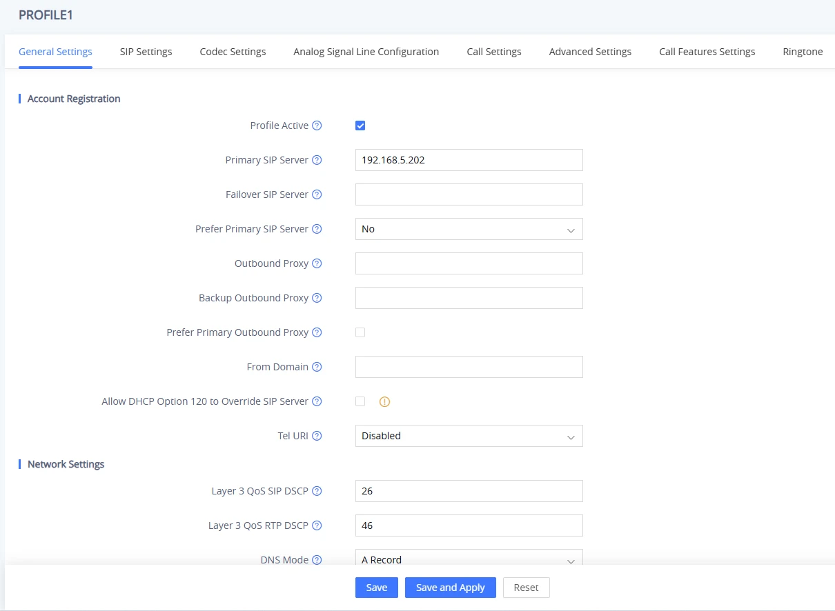
- Navigate to Port Settings → FXS PORT.
- In the SIP User ID field, enter the SIP user ID. This is typically a phone number or a numeric identifier.
- In the Authenticate ID field, enter the SIP authentication ID. This value may be the same as or different from the SIP User ID.
- In the Authenticate Password field, enter the SIP account password. For security reasons, the password is displayed as blank after it is saved.
- In the Name field, enter a name to identify the account.
- Select the previously configured Profile ID, ensure the port is enabled, then click Save and Apply at the bottom of the page to apply the configuration.
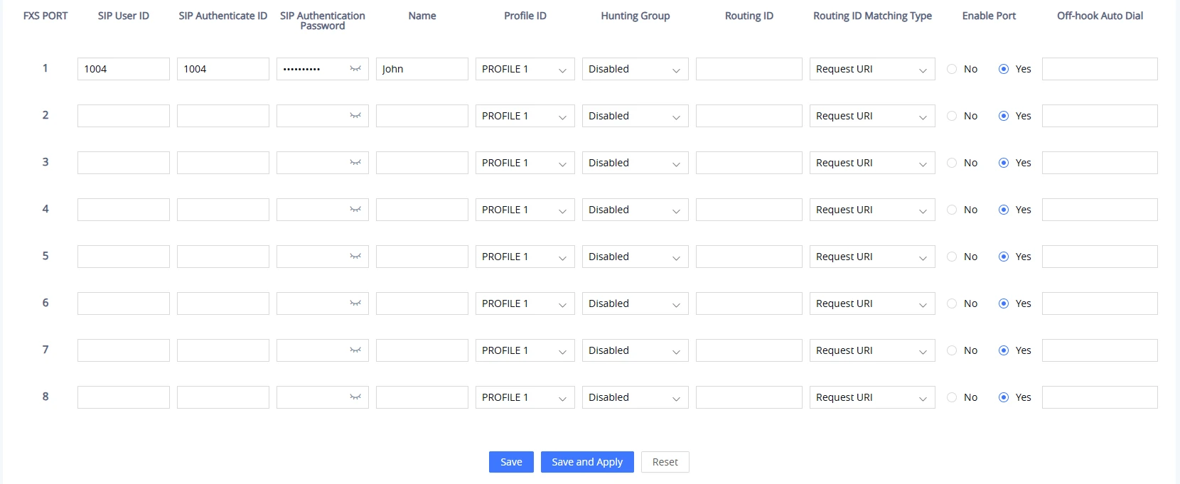
After applying the configuration, the account attempts to register with the SIP server. To verify the registration status, navigate to Status → Port Status → Registration in the HT81x V2 Web UI.
If the status displays Registered, the account has successfully registered with the SIP server. If the status displays Not Registered, verify the account settings or contact your VoIP service provider (ITSP) for assistance.
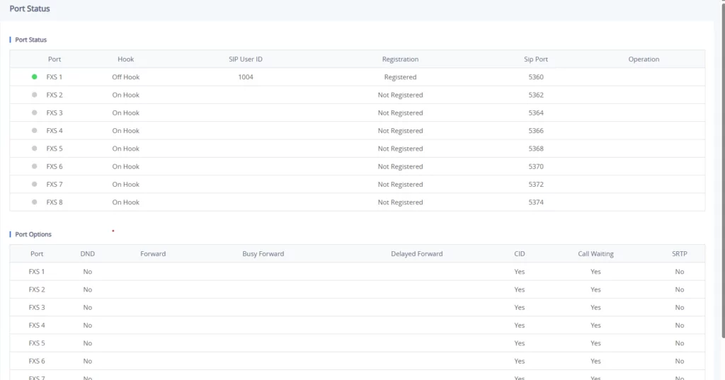
Call Features
The HT81x V2 support all the traditional and advanced telephony features.
Key | Call Features |
*02 | Forcing a Codec (per call) *027110 (PCMU), *027111 (PCMA), *02723 (G723), *02729 (G729), *027201 (iLBC), *02722 (G722). |
*03 | Disable LEC (per call) Dial “*03” +” number”. No dial tone is played in the middle. |
*16 | Enable SRTP |
*17 | Disable SRTP |
*18 | Enable SRTP per call. Meaning it’s only valid for the current call. |
*19 | Disable SRTP per call. Meaning it’s only valid for the current call. |
*30 | Block Caller ID (for all subsequent calls) |
*31 | Send Caller ID (for all subsequent calls) |
*47 | Direct IP Calling. Dial “*47” + “IP address”. No dial tone is played in the middle. |
*50 | Disable Call Waiting (for all subsequent calls) |
*51 | Enable Call Waiting (for all subsequent calls) |
*67 | Block Caller ID (per call). Dial “*67” +” number”. No dial tone is played in the middle. |
*82 | Send Caller ID (per call). Dial “*82” +” number”. No dial tone is played in the middle. |
*69 | Call Return Service: Dial *69 and the phone will dial the last incoming phone number received. |
*70 | Disable Call Waiting (per call). Dial “*70” +” number”. No dial tone is played in the middle. |
*71 | Enable Call Waiting (per call). Dial “*71” +” number”. No dial tone is played in the middle |
*72 | Unconditional Call Forward: Dial “*72” and then the forwarding number followed by “#”. Wait for dial tone and hang up. (dial tone indicates successful forward) |
*73 | Cancel Unconditional Call Forward. To cancel “Unconditional Call Forward”, dial “*73”, wait for dial tone, then hang up. |
*74 | Enable Paging Call: Dial “*74” and then the destination phone number you want to page. |
*77 | Enable set Offhook Auto-Dial. |
*78 | Enable Do Not Disturb (DND): When enabled all incoming calls are rejected. |
*79 | Disable Do Not Disturb (DND): When disabled, incoming calls are accepted. |
*87 | Blind Transfer |
*90 | Busy Call Forward: Dial “*90” and then the forwarding number followed by “#”. Wait for dial tone then hang up. |
*91 | Cancel Busy Call Forward. To cancel “Busy Call Forward”, dial “*91”, wait for dial tone, then hang up. |
*92 | Delayed Call Forward. Dial “*92” and then the forwarding number followed by “#”. Wait for dial tone then hang up. |
*93 | Cancel Delayed Call Forward. To cancel Delayed Call Forward, dial “*93”, wait for dial tone, then hang up |
*98 | Enable to play the registration ID. |
Flash/ Hook | Toggles between active call and incoming call (call waiting tone). If not in conversation, flash/hook will switch to a new channel for a new call. |
# | Pressing pound sign will serve as Re-Dial key. |
HT81x V2 Call Features
Ethernet Capture
Ethernet Capture records network traffic exchanged between the HT81x V2 and other devices, allowing administrators to analyze communication for troubleshooting and diagnostics.
When the HT81x V2 communicates with a SIP server over TLS, Ethernet Capture can also collect the secret key information generated during the TLS handshake. The downloaded capture package includes the packet capture file and an sslkeylogfile.txt file containing the client’s TLS session keys. These keys can be used to decrypt the captured TLS traffic in supported network analysis tools, such as Wireshark.
To capture the secret key information, follow the steps below:
- Initiate packet capture between the HT81x V2 and the server by navigating to Maintenance → System Diagnosis → Debug. Ensure With Secret Key Information is set to “Yes”, and press Start.
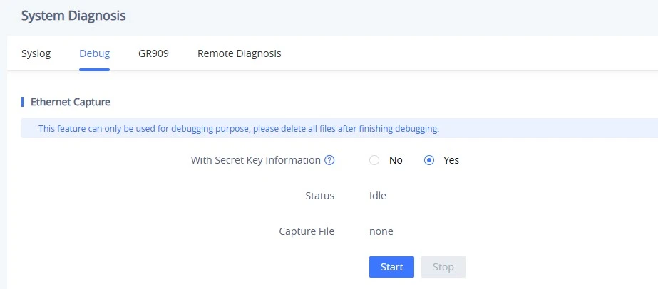
- Access Port Settings → PROFILE x → SIP Settings → SIP Basic Settings and set SIP Transport to TLS. The HT81x account will then re-register with the SIP server using the TLS transport protocol.
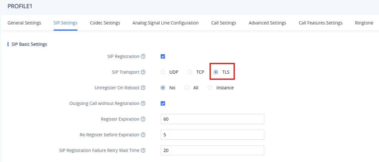
- After the HT81x resends the SIP REGISTER request to the server, press Stop to end the packet capture, then press Download when the capture file is available.
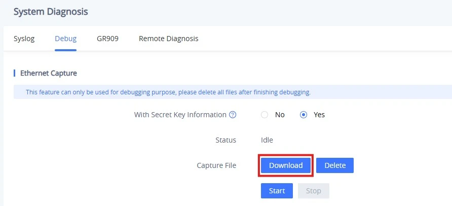
- After the file is downloaded, extract it to obtain the packet capture file and the
sslkeylogfile.txtfile containing the secret key information.

SCEP Configuration
To configure SCEP settings, navigate to System Settings → Security Settings → SCEP and follow the steps below:
- Enable SCEP: Enable SCEP service.
- SCEP Server URL: Enter the SCEP server enrollment URL provided by your Certificate Authority (CA) or Registration Authority (RA). This URL is used by the device to request certificates using the SCEP protocol.
- CA Fingerprint Information: Enter the fingerprint (thumbprint) of the issuing CA certificate. This field is optional and can be used to verify the identity of the CA before certificate enrollment.
- Challenge Password: Enter the challenge password required by the SCEP server to authorize certificate enrollment. If required, this password is provided by your CA or RA administrator.
- Local Public and Private Key Length: Select the key size used to generate the device’s public and private key pair. Ensure that the selected key length complies with your CA’s certificate policy. The default setting is “3072 bit”.
- The Name of Certificate Applicant: Enter the Common Name (CN) for the certificate applicant. This value is required and is included in the certificate request.
- The Country of Certificate Applicant Located: Enter the country where the certificate applicant is located. This field is optional and may be required by your CA policy.
- The State of Certificate Applicant Located: Enter the state or province where the certificate applicant is located. This field is optional and may be required by your CA policy.
- The Locality of Certificate Applicant Located: Enter the city or locality where the certificate applicant is located. This field is optional and may be required by your CA policy.
- The Organization of Certificate Applicant Located: Enter the name of the organization to which the certificate applicant belongs. This field is optional and may be required by your CA policy.
- The Organizational Unit of Certificate Applicant: Enter the organizational unit (OU) of the certificate applicant, such as a department or division. This field is optional and depends on the CA policy.
- User ID: Enter the user ID required to authenticate with the SCEP server, if applicable.
- Password: Enter the password required to authenticate with the SCEP server, if applicable.
- CA Certificate: View the CA certificate obtained through SCEP.
- Client Certificate: View the client certificate issued through SCEP.
- Client Certificate Alternative Name: Configure additional identifiers for the client certificate. These values are included as Subject Alternative Name (SAN) entries in the certificate. The supported identifiers are:
- DNS Name (dNSName): Enter a hostname or domain, for example www.example.com.
- IP Address (iPAddress): Enter the IPv4 or IPv6 address, for example 192.168.0.1 or 2001:db8::1.
- Email Address (rfc822Name): Enter an email address, for example user@example.com.
- X.500 Distinguished Name (directoryName): Enter an X.500 distinguished name, for example /C=US/ST=CA/L=Los Angeles/O=Example Inc./CN=www.example.com
- URI (uniformResourceIdentifier): Enter a uniform resource identifier, for example https://www.example.com.
- Kerberos Service Name (krb5PrincipalName): Enter a Kerberos service principal name, for example HTTP/www.example.com.
- The default setting is $MAC.local, which uses the device’s MAC address as the default identifier in the certificate request.
- Update Interval Before Certificate Expiration: Define the number of days (1–30) before certificate expiration that the device attempts to renew the certificate automatically. The default setting is “20”.
- Scope of Use: Select the modules that use SCEP-managed certificates. By default, certificates are used for Custom Certificate (SSL/TLS). Additional modules, such as 802.1X, OpenVPN, and TR-069, can also be configured to use certificates managed through SCEP.
- Press Save and Apply to complete the configuration. If the configuration is successful, the Status indicator next to Enable SCEP displays Success in green.
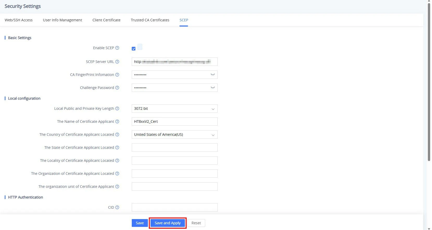
Rebooting HT81x V2 Remotely
Press the “Reboot” button at the bottom of the configuration menu to reboot the ATA remotely. The web browser will then display a message window to confirm that the reboot is underway. Wait 30 seconds to log in again.
UPGRADING AND PROVISIONING
The HT81x V2 can be upgraded via TFTP/HTTP/HTTPS/FTP/FTPS by configuring the URL/IP Address for the TFTP/HTTP/HTTPS/FTP/FTPS server and selecting a download method. Configure a valid URL for TFTP, HTTP/HTTPS, or FTP/FTPS; the server name can be an FQDN or an IP address.
Examples of valid URLs:
- firmware.grandstream.com
- fw.ipvideotalk.com/gs
Firmware Upgrade procedure
Please follow the steps below to upgrade the firmware version of your HT81x V2:
- Access your HT81x V2 UI by entering its IP address in your favorite browser.
- Enter your admin password (default: found on the sticker on the back of the unit).
- Press Login to access your settings.
- Go to the Maintenance 🡪 Upgrade 🡪 Firmware page, enter the IP address or FQDN of the upgrade server in the “Firmware Server Path” field, and choose to upgrade via TFTP, HTTP/HTTPS, or FTP/FTPS.
- Update the change by clicking the “Save and Apply” button at the bottom of the page. Then, “Reboot” or power cycle the HT81x V2 to update the new firmware.

Upgrading via Local Directory
- Download the firmware file from the Grandstream website
- Unzip it and copy the file into a folder on your PC
- From the HT81x V2 web interface, Maintenance → Upgrade → Firmware, you can browse your hard drive and select the folder where you previously saved the file.
- Click “Upload” and wait a few minutes until the new program is loaded.
Upgrading via Local TFTP/HTTP/HTTPS/FTP/FTPS Servers
For users who would like to use remote upgrading without a local TFTP/HTTP/HTTPS/FTP/FTPS server, Grandstream offers a NAT-friendly HTTP server. This enables users to download the latest software upgrades for their devices via this server. Please refer to the webpage:
https://www.grandstream.com/support/firmware
Alternatively, users can download, for example, a free TFTP or HTTP server and conduct a local firmware upgrade. A free Windows version of TFTP server is available for download from:
https://www.solarwinds.com/products/freetools/free_tftp_server.aspx
https://pjo2.github.io/tftpd64/
Instructions for local firmware upgrade via TFTP:
- Unzip the firmware files and put all of them in the root directory of the TFTP server.
- Connect the PC running the TFTP server and the phone to the same LAN segment.
- Launch the TFTP server and go to the File menu🡪Configure🡪Security to change the TFTP server’s default setting from “Receive Only” to “Transmit Only” for the firmware upgrade.
- Start the TFTP server and configure the TFTP server in the phone’s web configuration interface.
- Configure the Firmware Server Path to the IP address of the PC.
- Save and Apply the changes, and reboot the HT81x V2.
End users can also choose to download a free HTTP server from https://httpd.apache.org/ or use a Microsoft IIS web server.
Firmware and Configuration File Prefix and Postfix
Firmware Prefix and Postfix allow the device to download the firmware name with the matching Prefix and Postfix. This makes it possible to store all the firmware with different versions in one single directory. Similarly, Config File Prefix and Postfix allow the device to download the configuration file with the matching Prefix and Postfix. Thus, multiple configuration files for the same device can be stored in one directory.

Managing Automatic Upgrade
When “Automatic Upgrade” is set “Check”, the auto check will be done in the minute specified in this field. If set to “Every day in hour (0-23)”, the Service Provider can use P193 (Auto Check Interval) to have the devices do a daily check at the hour set in this field with either Firmware Server or Config Server. If set to “Weekly on day (0-6)”, the auto check will be done on the day specified in this field. This allows the device periodically to check if there are any new changes that need to be taken on a scheduled time. By defining different intervals in P193 for different devices, Server Provider can spread the Firmware or Configuration File download in minutes to reduce the Firmware or Provisioning Server load at any given time
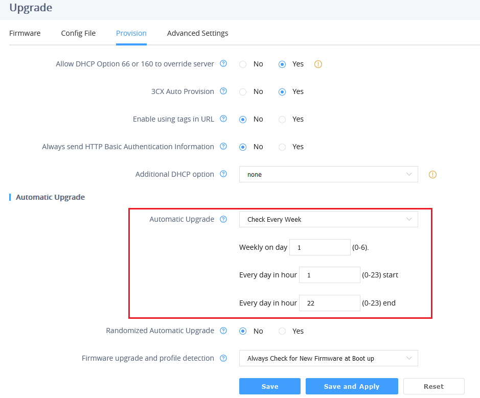
Managing Device using GDMS Cloud
The GDMS Device Management System is a cloud solution from Grandstream that facilitates the provisioning and management of Grandstream devices, including the HT8xx V2 ATAs.
The platform enables users to centralize the control and management of multiple HT8xx devices, deployed across various locations, on a single interface. It provides functionalities to upgrade, add, configure, and monitor HT8xx devices from one centralized dashboard.
For more details on the supported HT8xx models and their deployment to the GDMS platform, refer to the following guide: GDMS Unified Communications – User Guide.
If you don’t have a GDMS account yet, visit the following website to create one: GDMS.
Configuration File Download
Grandstream SIP Devices can be configured via the Web Interface as well as via a Configuration File (binary or XML) through TFTP, HTTP/HTTPS, or FTP/FTPS. The Config Server Path is the TFTP, HTTP/HTTPS, or FTP/FTPS server path for the configuration file. It needs to be set to a valid URL, either in FQDN or IP address format. The Config Server Path can be the same or different from the Firmware Server Path.
A configuration parameter is associated with each particular field in the web configuration page. A parameter consists of a Capital letter P and 1 to 5 (Could be extended in the future) digit numbers. i.e., P30 is associated with the “NTP Server” in the Web GUI🡪System Settings🡪Time and Language🡪Time Zone🡪NTP Server. For a detailed parameter list, please refer to the corresponding firmware release configuration template.
When the HT81x V2 boots up or reboots, it will send a request to download the xml file named “cfgxxxxxxxxxxxx.xml” followed by the binary file named “cfgxxxxxxxxxxxx”, where “xxxxxxxxxxxx” is the MAC address of the phone, i.e., “cfg000b820102ab” and “cfg000b820102ab.xml”. If the download of “cfgxxxxxxxxxxxx.xml” file is not successful, the provision program will download a generic cfg<Model>.xml file and then download cfg.xml. The configuration file name should be in lower-case letters.
HT81x supports DHCP option 67, allowing the provision of a custom name for the provisioning file. If DHCP option 67 is used, the following file download sequence will be applied:
Step 1: <option 67 bootfile>
Step 2: cfg<MAC>.xml →cfg<MAC>→cfg<Model>.xml →cfg.xml
Notes:
1. The Only acceptable Config file formats to be used when provisioning are XML or binary.
2. Make sure the MAC header on the Config file is the provisioned device’s MAC address, or you can remove the header completely.
3. When the <option 67 bootfile> is downloaded from the server, the cfg<MAC>.xml is not requested.
For more details on XML provisioning, please refer to:
https://documentation.grandstream.com/knowledge-base/sip-device-provisioning-guide/
Configuration and Firmware Upgrade through Resync SIP NOTIFY
HT81x V2 supports triggering firmware and configuration upgrade using Resync SIP NOTIFY. The event:resync NOTIFY allows the device to re-synchronize its configuration by checking the provisioning server to download any updates.
Below is an example of a resync SIP NOTIFY:
NOTIFY sip:device@domain.com SIP/2.0
Via: SIP/2.0/UDP 10.0.0.5:5060;branch=z9hG4bK-d4f2-9a75
Max-Forwards: 70
From: "Provisioning Server" <sip:provisioning@domain.com>;tag=prov-server
To: <sip:device@domain.com>;tag=device-987654
Call-ID: 987654xyz321
CSeq: 12345 NOTIFY
Event: resync
Content-Type: application/simple-message-summary
Content-Length: 45
CA Bundle Manifest
CA (Certification Authority) Bundle Manifest is a collection of trusted security certificates used to verify the authenticity of websites or services. It helps ensure secure and encrypted connections by confirming the identity of the remote server and protecting against unauthorized access and data interception.
You can access the CA Bundle Manifest by clicking on the bottom corner of the web page, as displayed in the screenshot below:

This will redirect you to a web page displaying a list of certification names and details, with their corresponding expiration dates:

RESTORE FACTORY DEFAULT SETTINGS
There are three (3) methods for resetting your unit:
Using the Reset Button
To reset default factory settings using the reset button, please follow the steps above:
- Unplug the Ethernet cable.
- Locate the reset hole on the back panel of your HT81x V2.
- Insert a pin in this hole and press for about 7 seconds.
- Take out the pin. All unit settings are restored to factory settings
Using the IVR Command
Reset default factory settings using the IVR prompt:
- Dial “***” for voice prompt.
- Enter “99” and wait for the “reset” voice prompt.
- Enter the encoded MAC address (Look below on how to encode the MAC address).
- Wait 15 seconds, and the device will automatically reboot and restore factory settings.
Encode the MAC Address
- Locate the MAC address of the device. It is the 12-digit HEX number on the bottom of the unit.
- Key in the MAC address. Use the following mapping:
Key | Mapping |
0-9 | 0-9 |
A | 22 (press the “2” key twice, “A” will show on the LCD) |
B | 222 |
C | 2222 |
D | 33 (press the “3” key twice, “D” will show on the LCD) |
E | 333 |
F | 3333 |
MAC Address Key Mapping
For example, if the MAC address is 000b8200e395, it should be keyed in as “0002228200333395”.
Reset from Web Interface (Reset Type)
- Access your HT81x V2 UI by entering its IP address in your favorite browser.
- Enter your admin password (default: found on the sticker on the back of the unit).
- Press Login to access your settings.
- Go to Maintenance 🡪 Restore Factory 🡪 Reset Type.
- Press the Reset button(after selecting the reset type).
• Full Reset: This will make a full reset
• ISP Data: This will reset only the basic settings, like IP mode, PPPoE, and Web port
• VOIP Data Reset: This will reset only the data related to a service provider, like SIP server, SIP user ID, provisioning, and others.
Reset using SIP NOTIFY
- Access your HT81x V2 UI by entering its IP address in your favorite browser.
- Go to the Port Settings → Profile # page.
- Set “Allow SIP Factory Reset” to “Yes”. (Default is No)
- Once a SIP NOTIFY with “event: reset” is received, the ATA will perform a factory reset.
CHANGE LOG
This section documents significant changes from previous versions of the admin guide for HT81x V2. Only major new features or major document updates are listed here. Minor updates for corrections or editing are not documented here.
Firmware Version 1.0.15.3
- Added support for the HTTP User-Agent header. [HTTP/HTTPS User-Agent]
- Added support for Layer 2 QoS 802.1p Priority Value. [Layer 2 QoS 802.1p Priority Value]
- Added wildcard support across provisioning settings. [Upgrading and Provisioning]
- Add support for Zoom X-switch-info SIP Header. [Use X-switch-info Header]
Firmware Version 1.0.15.1
- Added the ability to configure the VLAN settings via TR069. [Enable Manual VLAN Configuration]
Firmware Version 1.0.13.5
- Added support for displaying Vendor Default Config Version information on the System Info page. [Vendor Default Config Version]
- Added support for SCEP protocol. [SCEP] [SCEP Configuration]
- Added support for direct IP calls in Off-Hook Auto Dial. [Off-Hook Auto Dial]
- Added support for the options “AES-128-GCM”, “AES-256-GCM”, and “CHACHA20-POLY1305” in OpenVPN® Encryption. [OpenVPN® Encryption]
- Renamed the setting “WAN Side Web/SSH Access” to “Enable Web/SSH Access”. [Enable Web/SSH Access]
- Added support for T.38 Talker Echo Protection (TEP). [Enable T.38 TEP]
- Added support for the option “Yes with Attended Transfer Upon Onhook” in Flash Digit Control. [Flash Digit Control]
- Added support for Use P-Early-Media Header. [Use P-Early-Media Header]
- Added support for Ringback Tone at No Early Media. [Ringback Tone at No Early Media]
- Added support for Caller ID Transmission Mode. [Caller ID Transmission Mode]
- Added support for Busy/Reorder Tone Delay Timer After Loop Current Disconnect. [Busy/Reorder Tone Delay Timer After Loop Current Disconnect]
Firmware Version 1.0.11.4
- Added support for HTTP/HTTPS Proxy setting. [HTTP/HTTPS Proxy]
Firmware Version 1.0.9.4
- Added P-values to configure settings not available in the Web UI. [Force Default Password Change] [User/Viewer Password Setting Display] [TR-069 Settings Page Display]
Firmware Version 1.0.9.3
- Added “TLS 1.3” option for “Minimum TLS Version” [Minimum TLS Version]
- Added “TLS 1.3” option for “Maximum TLS Version” [Maximum TLS Version]
- Added ability to configure B-timer [SIP Timer B]
- Added ability to configure F-timer [SIP Timer F]
Firmware Version 1.0.7.5
- Adjusted DHCP Option 160 to a higher priority than Option 66 on HT8xx v2 to align with other GS devices. [Allow DHCP Option 66 or 160 to override server]
- Added support for the E911 SIP Geolocation Header Format. [Geolocation Header Format]
- Added Cloudflare as a DDNS provider in the DDNS Server field. [Cloudflare]
- Added support for the Vonage OEM ID. [Vonage]
- Updated the default value of “Web Access Mode” to “0 – HTTPS.” [Web Access Mode]
- Changed the default value of “Profile Active” to “0 – No.” [Profile Active]
- Changed the default value of “Enable Port” to “0 – No.” [Enable Port]
- Changed the default value of “Use Random SIP Port” to “1 – Yes.” [Use Random SIP Port]
- Changed the default value of “Use Random RTP Port” to “1 – Yes.” [Use Random RTP Port]
- Changed the default value of “Enable/Disable Weak Cipher Suites” to “8 – Disable All Of The Above Weak TLS Cipher Suites.” [Enable/Disable Weak Cipher Suites]
- Changed the default value of “Minimum TLS Version” (P22293) to “12 – TLS 1.2.” [Minimum TLS Version]
- Added support for debug info containing security-related logs in Syslog. [Security-related debug logs]
- Added support for “CSeq Tracking Mode”. [CSeq Tracking Mode]
- Added support for “Radius bypass locked state”. [Enable Bypass Locked State]
- Added support for “Maximum Transmission Unit (MTU)”. [Maximum Transmission Unit (MTU)]
- Added support for enabling TR069 through the management interface. [Enable TR069 Through Management Interface]
- Added support for enabling RADIUS through the management interface. [Enable Radius Through Management Interface]
- Updated the Custom Order for Config Files (P8501) config file download request sequence to start from cfgMAC.xml. [Config Provision Order]
- Added the default value as: cfg$mac.xml;cfg$mac;cfg$product.xml;cfg.xml. [Config Provision Order]
- Added the ability to periodically save system time to a time file. [System Info]
- Added support for OpenVPN TLS Key. [OpenVPN® TLS Key] [OpenVPN® Additional Options] [OpenVPN® TLS Key Type]
Firmware Version 1.0.5.10
- Added the option “Follow SIP Transport” for SRTP Mode settings. [SRTP Mode]
Firmware Version 1.0.5.9
- Updated the default value of Web Access Mode to HTTPS. [Web Access Mode]
Firmware Version 1.0.5.7
- No major changes.
Firmware Version 1.0.5.5
- No major changes.
Firmware Version 1.0.5.4
- No major changes.
Firmware Version 1.0.5.3
- Added support OpenVPN® failover option. [OpenVPN® Server Secondary]
- Added support for SIP PUBLISH method (RFC 6035). [RFC 6035]
- Added support for Config Provision Order in Config Provision. [Config Provision Order]
- Added support for Multiple DIDs per FXS Port. [Routing ID]
- Added support for Enable Multiple Sampling Rates in SDP telephone-event. [Enable Multiple Sampling Rates in SDP telephone-event]
- Added support for “Hunting Group Registration Mode” on HT81X V2. [Hunting Group Registration Mode]
- Added option of “2 – Parallel” for Hunting Group Type(P4395/4396) on HT81X V2. [Hunting Group Type]
Firmware Version 1.0.3.10
- No major changes.
Firmware Version 1.0.3.8
- Added support to initiate a Re-Invite for fax transmission when the fax machine is the sender. [Re-INVITE Upon CNG Count]
Firmware Version 1.0.3.5
- Added support for 55Vrms Ring Voltage (For New Zealand/Australia) SLIC. (P4234/4235 Ring Power. 0 – 45Vrms default, 3 – 50Vrms, 4 – 55Vrms). [Ring Power]
- Added “HELD Use LLDP Information”. [HELD Use LLDP Information]
- Added support to enable LLDP. [Enable LLDP]
- Added “LLDP TX Interval”. [LLDP TX Interval]
- Added support to enable CDP. [Enable CDP]
- Added “Use Random SIP Registration Failure Retry Wait Time”. [Use Random SIP Registration Failure Retry Wait Time]
- Added the ability to configure the minimum and maximum values for the registration retry timer. [Random SIP Registration Failure Retry Wait Time Range]
- Added support to configure a static DNS SRV record. [Static DNS Cache]
- Added support for firmware upgrade via resync SIP Notify. [Configuration and Firmware Upgrade through Resync SIP NOTIFY]
Firmware Version 1.0.1.14
- This is the initial Firmware.