
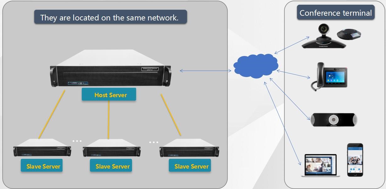
Multiple IPVT10 servers can be deployed under the same network to expand MCU capabilities. The Clustering feature allows the load balancing between multiple IPVT10 which will allow the users to make conferences in better conditions and in a balanced environment.
Setup Method
In cluster mode, users could use 1 IPVT10 server as the host server, and the other IPVT10 servers can be used as the slave servers.
There are two ways to connect the host server with the slave servers:
- Under the same LAN (such as in the same office)
- Under the external network (such as setup the cluster in different offices)
The conferencing capability of the cluster is shown on below table:
MCU Capability | 1 Host Server | Adding 1 Slave Server | Adding N Slave Servers |
Max Video Feeds | 120 | +120 | +N*120 |
Max Participants | 300 (Dual NICs) 200 (Single NIC) | +200 | +N*200 |
Max Meeting Number | 10 | +10 | +N*10 |
For Single Meeting | Up to 120 video feeds Up to 300 participants | Up to 120 video feeds Up to 300 Participants | Up to 120 video feeds Up to 300 Participants |
Installation Process
The process to setup cluster servers is shown as below:
- Select an IPVT10 server as the host server, install the IPVT10 server and setup the device.
- Install the IPVT10 slave servers, and setup the devices.
- Complete the setup and check the configuration on each device.
HOST SERVER INSTALLATION AND SETUP
Setup Host Server
- Install the IPVT10 server following the IPVT10 Quick Installation Guide. Please refer to the IPVT10 Quick Installation Guide on https://www.grandstream.com/support
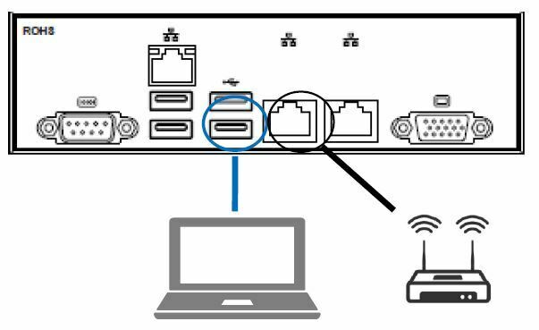
- Connect your PC to the Network Interface 1 of the IPVT10 server using an Ethernet cable.
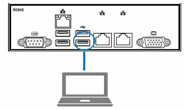
- Login the IPVT10 server with your browser, the address is “192.168.88.88/deploy”, and the default username and password are “admin/change_me”.
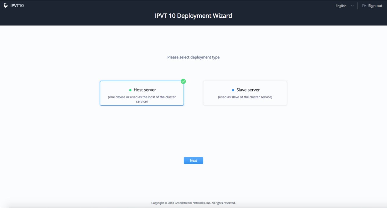
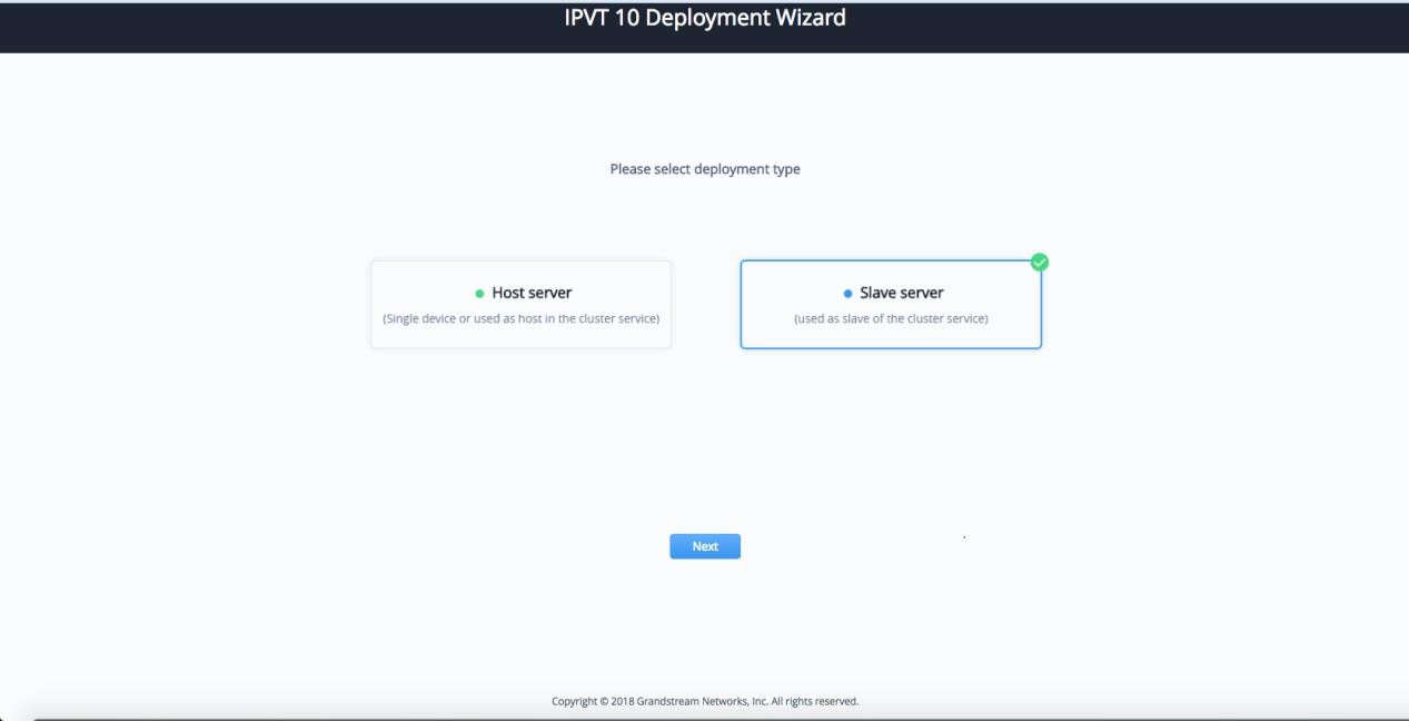
- Access the IPVT10 Deployment Wizard page, and select “Host Server”, then click on “Next” to set the IPVT10 server as the host server.
- Network Settings: The host server allows users to configure dual networks in the device.
- Time Settings, SMTP Mailbox and Meeting Management Platform are necessary settings. Users need to configure the settings before using the host server.
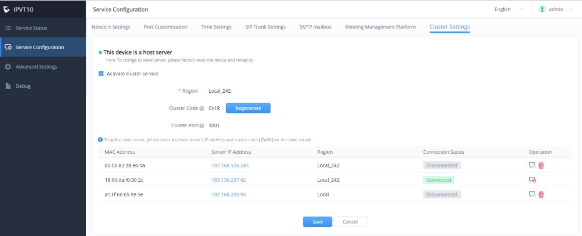
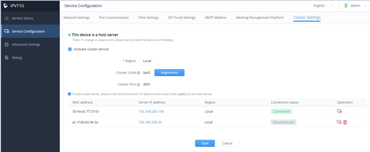
- Users must enable the Cluster Service feature in the IPVT10 host server. Users could click on “Cluster Settings”, and check the option “Active Cluster Service” to active the Cluster Service in the IPVT10 host server, as the figure shown below:
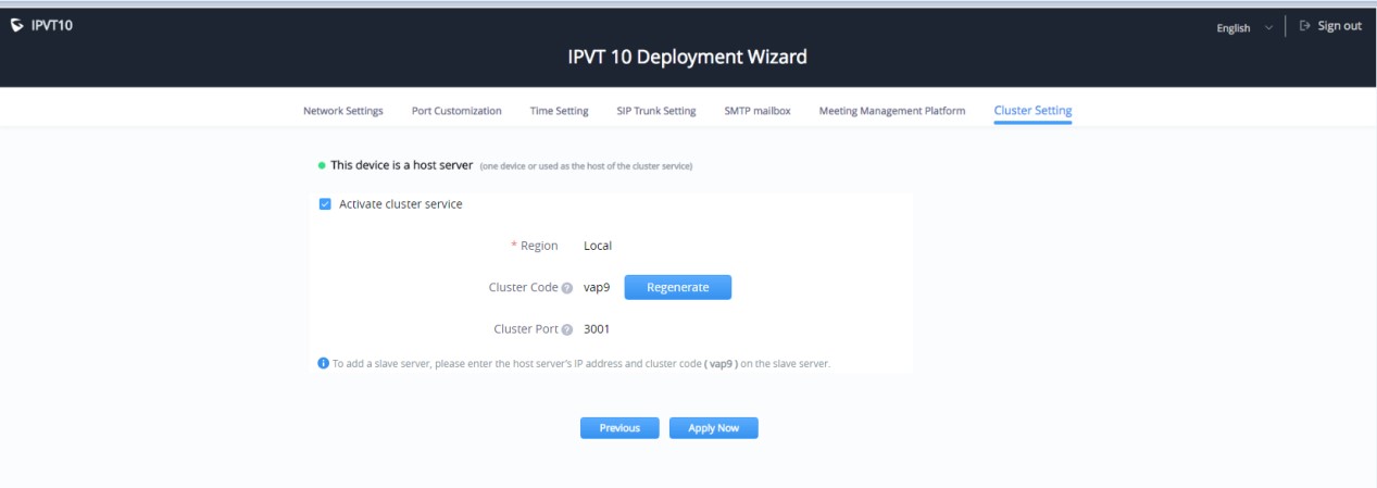
- Click on “Apply Now” to apply the configuration in the IPVT10 host server.
Enable Cluster Service for Active IPVT10 Server
If users want to enable Cluster Service in an active IPVT10 server, users could follow the steps below:
Prerequisites:
Required system version: 1.0.1.5.
If the system version is too low, please upgrade your IPVT10 device before enabling Cluster Service.
Steps:
- Login IPVT10 Web UI.
- Go to “Service Configuration” → “Cluster Settings” options and check the option “Active Cluster
Service” to activate Cluster Service in the IPVT10 server, and setup the device as the host server.
- User must click to save the configuration and click on “Apply Now” to apply the entire configurations.
When the deployment is complete, it will take effect immediately.
- In the slave servers, users need to input the “Cluster Code” (e.g. “Cv1R” in the screenshot above, case sensitive). Then, the connection between the cluster host server and slave server will be established.
Change Slave Server to Host Server
If the user wants to change the slave server to the host server, the user could follow the steps below:
- Login the Web UI of the IPVT10 slave server, go to “Advanced Settings”, and click “Factory Reset” option to reset the IPVT10 slave server.
- Setup the IPVT10 device again following the section HOST SERVER INSTALLATION AND SETUP.
SLAVE SERVER INSTALLATION AND SETUP
Setup Slave Server
- Install the IPVT10 server following the IPVT10 Quick Installation Guide. Please refer to the IPVT10 Quick Installation Guide on https://www.grandstream.com/support
- Connect your PC to the Network Interface 1 of IPVT10 device with Ethernet cable. Network Interface 2 of IPVT10 device needs to be connected with 1000M network, and the IPVT10 slave server needs to be able to reach the IPVT10 host server.
- Login the IPVT10 server with your browser, the address is “192.168.88.88/deploy”, and the default username and password are “admin/change_me”.
- Go to IPVT10 Deployment Wizard page, select “Slave Server”, and click “Next” for next step.
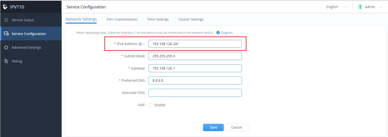
- Network Settings: The IPVT10 slave server only allows users to configure single network. The configured IP address must be able to connect with the host server.
- Time Settings is necessary configuration for IPVT10 slave server.
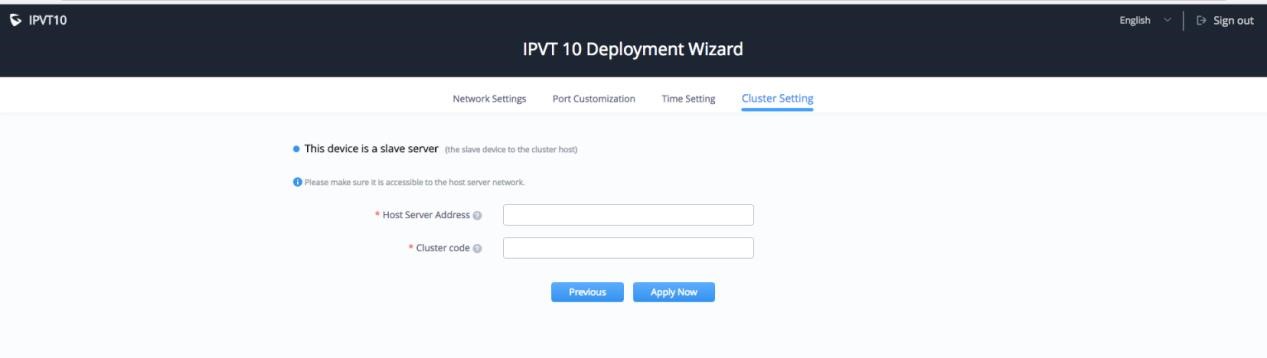
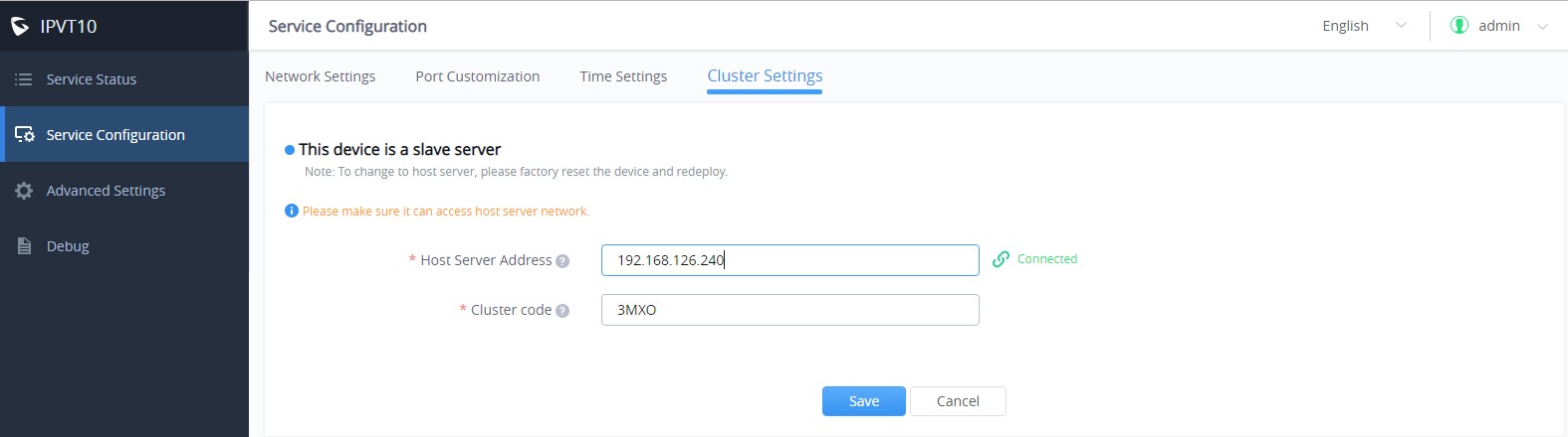
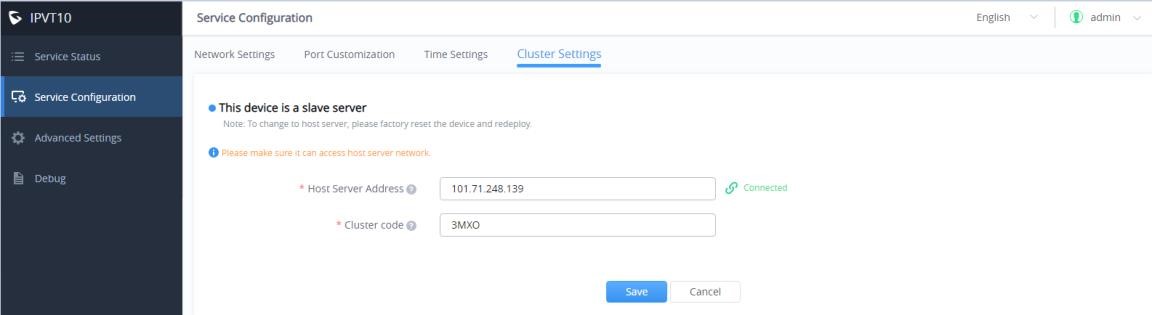
- Configure “Cluster Settings” options, as the figure shown below:
-
The slave server is required to configure the host server IP address and the cluster code:
- Input the IP address of the host server, this IP address must be able to be reached by the slave server.
- Input the Cluster Code of the host server, case sensitive.
- Click on “Apply Now” to apply the configuration in the IPVT10 slave server.
Change Host Server to Slave Server
Steps:
- Login the Web UI of the IPVT10 host server, go to “Advanced Settings”, and click “Factory Reset” option to reset the IPVT10 host server.
- Setup the IPVT10 device again following the section SLAVE SERVER INSTALLATION AND SETUP.
NETWORK CONFIGURATION EXAMPLE
Under Same LAN
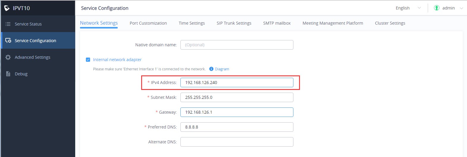
The host server and all slave servers are under the same LAN (same office). Users need to assign the IP addresses for each IPVT10 server.
- The host server is configured with an internal IP address, such as 192.168.126.240.
- The slave server is configured with the same LAN network, such as 192.168.126.241.
- Configure the host server’s IP address in each slave server, such as 192.168.126.240. When users click on “Apply Now” to apply the configuration in the slave server, users could see the host server connection status – “Connected” on the Web UI as the screenshot shows below:
Under Different Public Network
The IPVT10 host server could be in the office A, and the other slave servers could be in other different offices. Users could build the cluster servers through the public network with host server and slave servers.
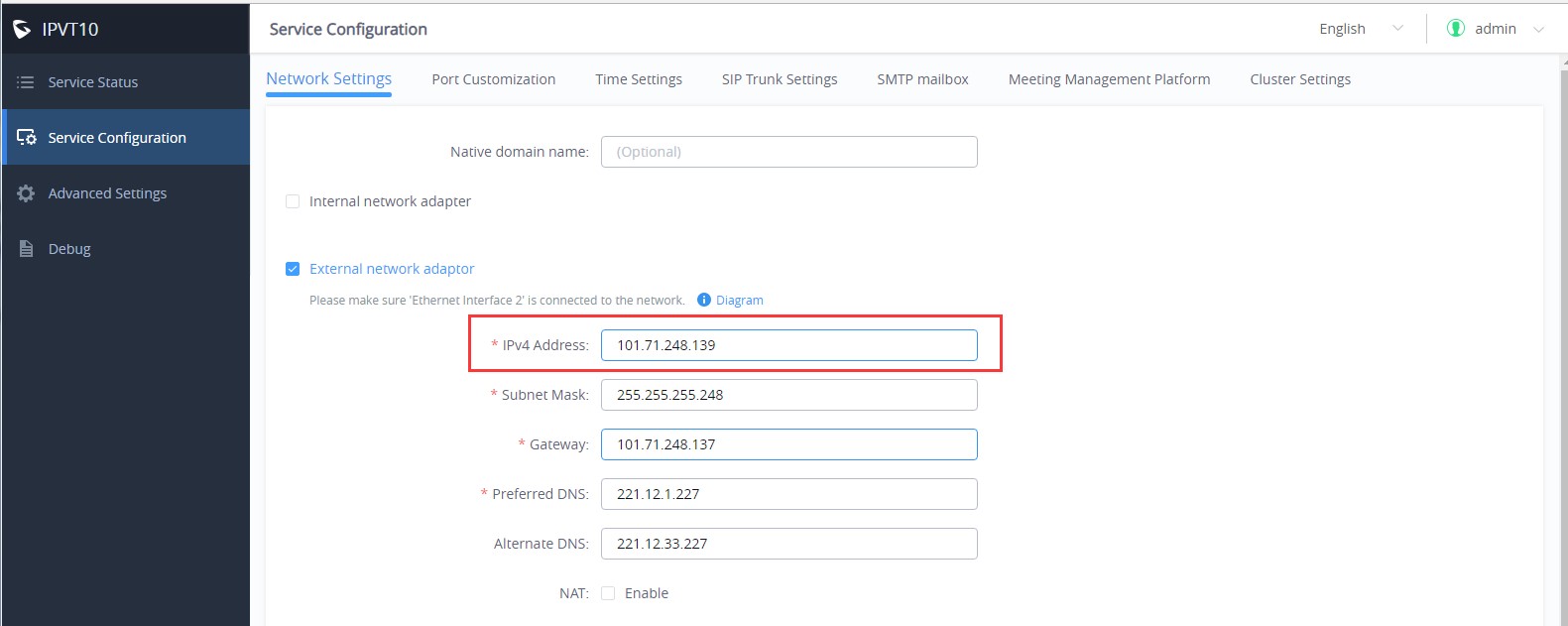
- Configure the public network IP address in the host server. For example, go to “External Network
Adapter”, and configure IP address 101.71.248.139 for the host server.
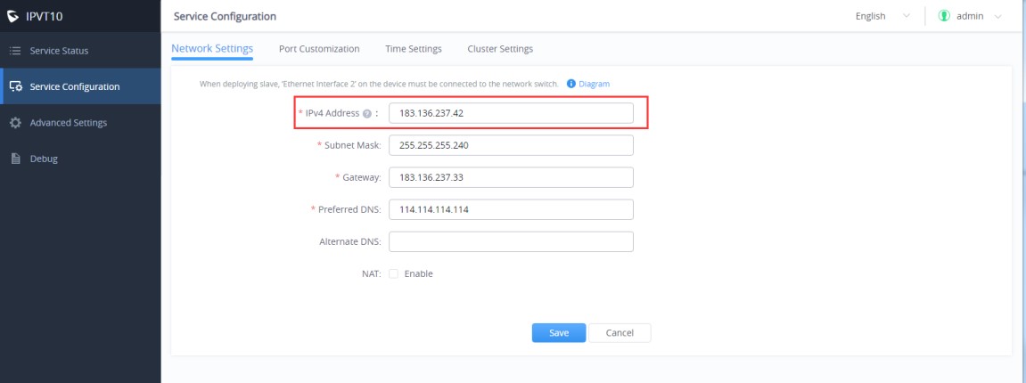
- Configure the public network IP address in the slave server, such as 183.136.237.42.
- Configure the public network IP address of the host server in each IPVT10 slave server, such as 101.71.248.139. If NAT is configured in host server, users need to input the NAT IP address.

CONFIGURATION REVIEW
After configuring the Cluster, users can verify the configuration and status of the Host/Slave connection.
This can be verified from the 2 side, Host side or Slave side.
- Login the Web UI of the IPVT10 host server and go to “Service Configuration” → “Cluster Settings” to check the connection status of each IPVT10 slave server.
- Or, users could login the Web UI of the IPVT10 slave server and go to “Service Configuration” → “Cluster Settings” to check the connection status with the host server.
CHECK STATUS OF EACH SLAVE SERVER
Users could check the slave server connection status, system version number, number of conferences, network conditions, and the status of the hard disk on IPVT10 host server’s Web UI.
- Login the Web UI of the IPVT10 host server.
- Go to “Service Status”, and check the information of each slave server, as the screenshot shows below:
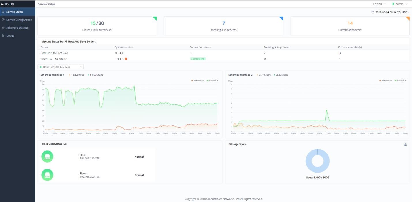
- If the system version number of the slave server and host server are inconsistent, there will be a prompt
 next to the version number. The recommendation is the host server and slave server are using the same system version.
- It also displays the number of ongoing conferences and current participants of the host server and each slave server in the real time. If users reboot the server, or update the configuration in the server, the ongoing conference will be forced to end.
- Users could view the network bandwidth of each slave server. Users could click the drop-down menu to select the host server or certain slave server to view the network bandwidth.
- Device Status: Users could view the status of the hard disk of the host server and all slave servers.
Below the explanations of each Hard Disk status icons:
 | This icon represents the normal status of the Hard disk. |
 | This icon means that the Hard disk status is abnormal, and the specific disk symbol will be |
 | This icon means that the drive letter is rebuilt, and the specific disk symbol is displayed. After |
UPGRADE SYSTEM VERSION
If users need to upgrade the system version, it is recommended that both the host server and the slave servers are upgraded to the same system version. Otherwise, it may cause some issues for the conference.