
OVERVIEW
IPVT10 is an enterprise full-HD conference system that integrates multiple service units such as MCU, media service, WebRTC service, and conference management. IPVT10 includes a full set of conferencing system solutions in one single device. The product is mainly used in small and medium enterprise for internal conferences and communications (internal communications between headquarters and branch offices), government-to-business communications, remote training/education, and etc.
Product Features
- Support two-way audio/video real-time conference in 1080P / 30fps / H.264 for maximum 120 attendees.
- Support two-way audio real-time conference for maximum 200 attendees.
- Support one-way video (receiving video) and two-way audio real-time conference in 1080P/30fps/H.264/VP8 for maximum 200 attendees.
- Support up to 10 conferences at the same time.
- Support up to 49 sharing cameras at the same time during the conference.
- Support GVC3200/3202, GVC3210, WebRTC client (Firefox, Chrome, Edge, Opera, Safari, etc.), IE11, IOS/Android mobile applications and other SIP Phones
- Packets loss resistance rate during the conference is as high as 30%.
- Conference Control features: Presentation, Video Layouts, Conference Control, Chat, Q&A, Recording, and etc.
- Multiple Meeting Modes: Schedule Meetings, Instant Meetings, and Personal Meetings.
- Multiple Meeting Types: Video Conference, Webinar, and Recurring Meetings.
- Complete conference management platform and functional post-meeting statistics.
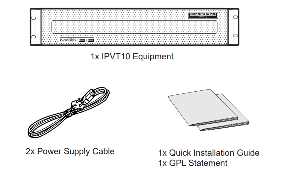
PACKAGE CONTENTS
HARDWARE SPECIFICATIONS
| Power Supply | – Redundant Power. – 550W. – Only AC power supply supported. |
| Applicable Cabinet | 2U Rackmount Design, and it supports 19” cabinets and rails. |
| Equipment Size | Bare Equipment size: Height 88mm * Width 430mm * Depth 650mm. |
| USB Interfaces | – 3x USB 3.0 (2 rear, 1 via header) – 3x USB 2.0 (2 rear, 1 via header) |
| LAN Interfaces | – 2x RJ45 Gigabit Ethernet LAN Ports. – 1x RJ45 Dedicated IPMI LAN Port. |
| Display Interfaces | 1x VGA Port. |
| Operating Temperature | 0°C – 45°C |
| Relative Humidity | 10% – 90% (Non-condensing) |
MOUNTING IPVT10 TO CABINET
Users can install the IPVT10 in a 19-inch cabinet that conforms to the IEC (International Electro-Technical Commission) 60297 standard.
- The IPVT10 server is heavy and we suggest to carry it by two people at least.
- The cabinet has been installed and we suggest a space of at least “2U” (1U=44.45mm) needs to be reserved.
- Users can select the regular rail for installation, or optional installation (Rails and Rail Holders are not included within the package contents).
Users need to follow the steps below to mount IPVT10 to Cabinet:
- Remove the rail holder and the rails by loosening the 4 screws first, and then removing the front and back rail holders.
- Install the inner rail to the server case. Pull the inner rail out of the rail until it cannot be pulled.
- Fix the inner rail with 2 screws to the server case. Fit the smooth surface of the inner rail to the side of the server case, and match the screw holes on the inner rail with the screw holes on the server case. Hold the inner rail tightly against the server case and tighten with the screws.
- Repeat steps 1 to 3 to install the other inner rail on the other side of the server case.
- Install the rail holder to the cabinet. Make sure the installation position of BACK PANEL the front rail holder on the cabinet, align the two fixing holes between the rail holder and the cabinet corner, tighten the screws. Then, according to the depth of the cabinet (the depth of the cabinet is 650mm), adjust the back rail holder properly, and align the two fixing holes between the back rail holder and the cabinet corner at the back of the cabinet, tighten the screws. (Note: Please make sure that the front and back rail holders are horizontal.)
- Repeat the above steps to install the other front and back rail holders to the cabinet. (Note: Please make sure that the left and right side rails are horizontal)
- Lift the server up and close to the cabinet so that the back of the server faces the front of the cabinet. Insert the inner rails on the two sides of the server into the front and back rail holders on the cabinet, align the fixing holes and tighten the screws.
- When the installation is completed, push the server into the cabinet.
EQUIPMENT SETUP
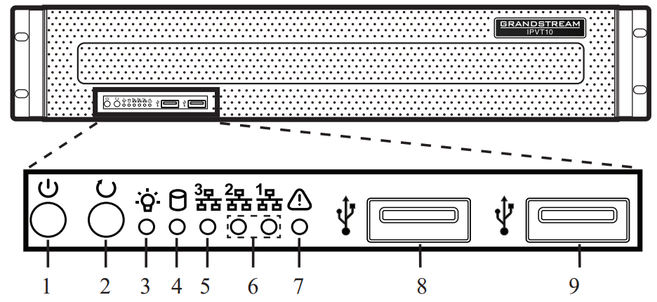
| NO. | NAME | NO. | NAME | NO. | NAME |
| 1 | Equipment Switch | 4 | Hard Disk Indicator | 7 | Failure Indicator |
| 2 | Reboot Switch | 5 | Network Connection Indicator | 8 | USB 2.0 Interface |
| 3 | Power Indicator | 6 | Ethernet Interface Indicators | 9 | USB 3.0 Interface |
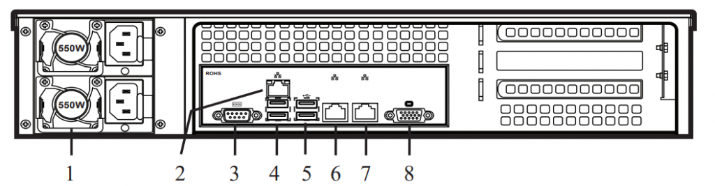
| NO. | NAME | NO. | NAME |
| 1 | Power Supply Interfaces | 5 | USB 3.0 Interfaces |
| 2 | IPMI Interface | 6 | Ethernet Interface 1 |
| 3 | COM Interface | 7 | Ethernet Interface 2 |
| 4 | USB 2.0 Interfaces | 8 | VGA Input Interface |
CONNECTING THE IPVT10 SERVER
- Connect Network cables: In order to ensure using IPVT10 properly, users need to connect the server to a Gigabit Switch. Connect the RJ45 Ethernet Cable with Ethernet interface 1 and connect the other end to Gigabit Switch. Do the same for Ethernet interface 2.
- Connect Power Supply: Connect the standard power supply cable with the equipment and plug it into the AC Power supply.
POWERING ON THE IPVT10 SERVER
When the equipment is properly installed, users can power on the equipment by proceeding as follows:
Check before Power on
Before powering on the equipment, users need to ensure that the equipment meets the following conditions:
- If the equipment is installed in a cabinet, please ensure that the screws are fixed, and the equipment has enough space for heat dissipation.
- The connections of the cables on the equipment are normal.
- The input power and current are within the working range of the equipment.
- The distance between the power cable and the Ethernet cable outside the cabinet must be greater than 30 mm.
Power on Equipment
Once the previous conditions are checked, the users can power up the IPVT10 Server. In order to make the equipment run properly, users need to press the equipment switch in the front panel of the server to power on the equipment. The indicator will turn to solid green.
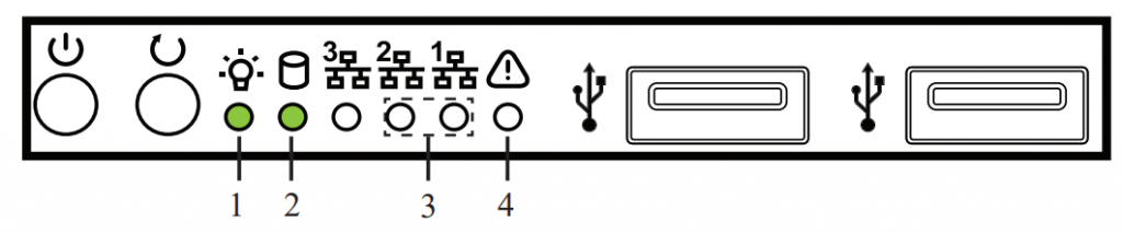
Check after Power on
After the equipment is turned on, please check the following indicators to make sure the equipment is working properly.
| NO. | Name | Description |
| 1 | Power Indicator | • When the equipment is on and connected to the power supply: the light is solid green. • When the equipment is off and the power supply is not connected with the equipment: the light is off |
| 2 | Hard Disk Indicator | • When the hard disk is writing/reading: the light is solid blue. • When the hard disk is faulted or work off: the light is off. |
| 3 | Network Connection Indicators | • When the network connection is normal: the light is flashing yellow. • When the network connection is abnormal or the network is not connected with the equipment: the light is of |
| 4 | Failure Indicators | • Normal condition: the light is always off. • When the equipment is faulted: the light is flashing red. |
CONFIGURING THE IPVT10 SERVER
- Please make sure that the IP address of the PC is under the same network segment as the server’s. If not, users need to go to “Network” configuration page of the PC to setup the network segment as the same as IPVT10 server’s.
- Enter the IP address (http://192.168.88.88) of the equipment in the browser of the PC, and press “Enter” to access the configuration page, as the screenshot shows below:
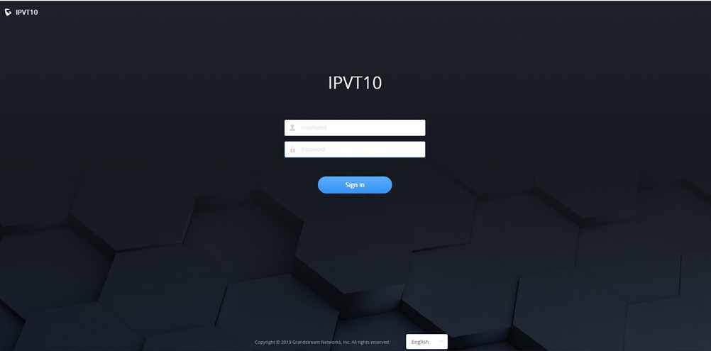
- Input login user name and password.
- (Optional) Users could select the language on the list at the bottom of the configuration page.
- Click to login to the configuration page.
If there is an IP conflict, users can connect the PC directly to the server via an Ethernet cable for configuration purpose. Follow the steps below:
- Unplug the Ethernet cable from the Ethernet Port 1 on the IPVT10 equipment.
- Then, connect the Ethernet Port 1 and a PC with an Ethernet cable.
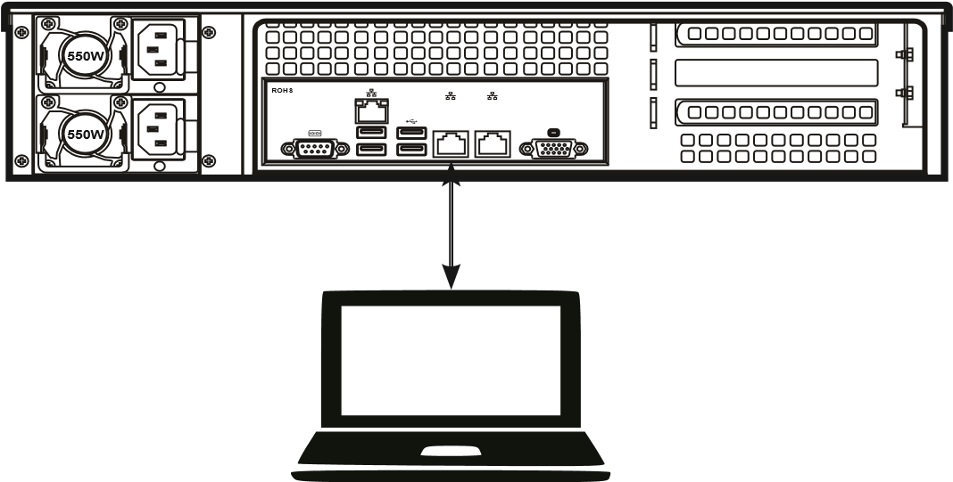
- Enter the IP address (http://192.168.88.88) of the equipment in the browser of the PC, and press “Enter” to access the configuration page.
- Input login user name and password.
- (Optional) Users could select the language on the list at the bottom of the configuration page.
- Click to login to the configuration page.