

The GDS372x supports the Safe Room feature, a security solution designed to control access to a single-door secure area using linked indoor and outdoor access units. This feature enhances protection by ensuring that only one authorized user can access the room at a time while preventing unauthorized entry from the opposite side when the room is occupied.
The Safe Room solution integrates access control, alarm signaling, door status monitoring, door open duration detection, and snapshot capture to provide a secure environment suitable for high-security scenarios.
The indoor and outdoor units operate together through linked alarm interfaces, allowing both devices to monitor room occupancy status and door activity in real time.
In addition to local access control, SecureAccess provides remote monitoring and management capabilities, including live video preview and remote door opening through the application during emergency situations.
This guide describes the Safe Room feature configuration, device wiring & interconnection requirements, and operational behavior for both indoor and outdoor access scenarios.
Safe Room Alarm
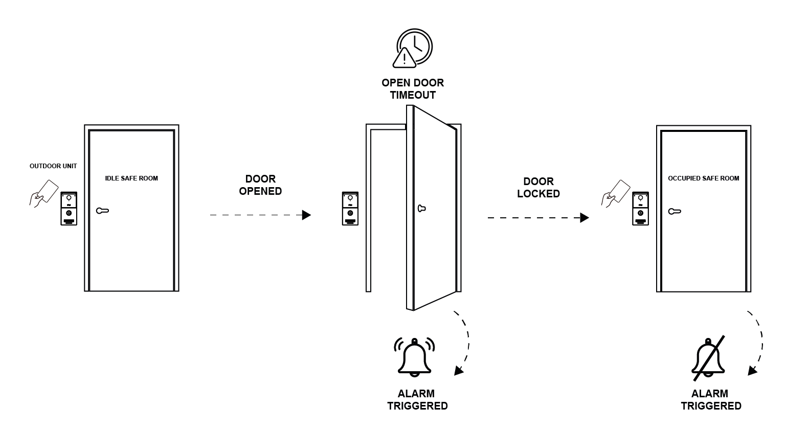
The Safe Room alarm is a security feature that monitors whether the safe room is in an idle or occupied state and prevents entry attempts from the outdoor unit while the room is occupied. The alarm is triggered under the following conditions:
- When the safe room is occupied and an attempt is made to open the door from the outdoor unit, the device generates a ‘Security Room Occupied’ alarm record locally and/or through cloud services and executes the configured alarm actions defined in the associated profile.
- When the safe room is in idle state and the door is opened via card or password authentication from the outdoor or indoor unit, but is not closed within the duration configured in Open Door Timeout Alarm. In this case, the device generates an Open Door Timeout alarm and executes the configured alarm actions defined in the associated profile. Both Safe Room Alarm and Open Door Timeout Alarm must be enabled.
Scope of Usage
The Safe Room feature is intended for environments that require controlled, single-person entry into secured areas. Common deployment scenarios include:
- Data Centers and Server Rooms: Prevents tailgating by ensuring only one individual enters the secured area at a time while maintaining a record of all access events.
- Research Laboratories: Controls access to sensitive research facilities where personnel must be individually verified before entering restricted zones.
- Financial Institutions: Secures access to cash handling areas, vaults, and other high-security locations by preventing unauthorized or simultaneous entry.
- Government and Military Facilities: Provides an additional security layer for areas containing classified information or critical infrastructure.
- Pharmaceutical and Manufacturing Facilities: Restricts access to controlled production areas where personnel movement must be monitored and audited.
- Corporate Security Zones: Protects executive offices, security operation centers, and other restricted business areas from unauthorized access.
In these environments, the Safe Room acts as an intermediary security checkpoint, allowing personnel verification, preventing multiple occupants from entering simultaneously, and generating alerts when abnormal access conditions are detected.
GDS372x Wiring
The Safe Room feature relies on proper communication between the indoor and outdoor units to ensure correct room status detection, alarm triggering, and door operation behavior. To achieve this functionality, the devices must be connected using the appropriate wiring interfaces and relay connections
Fail-safe Strike
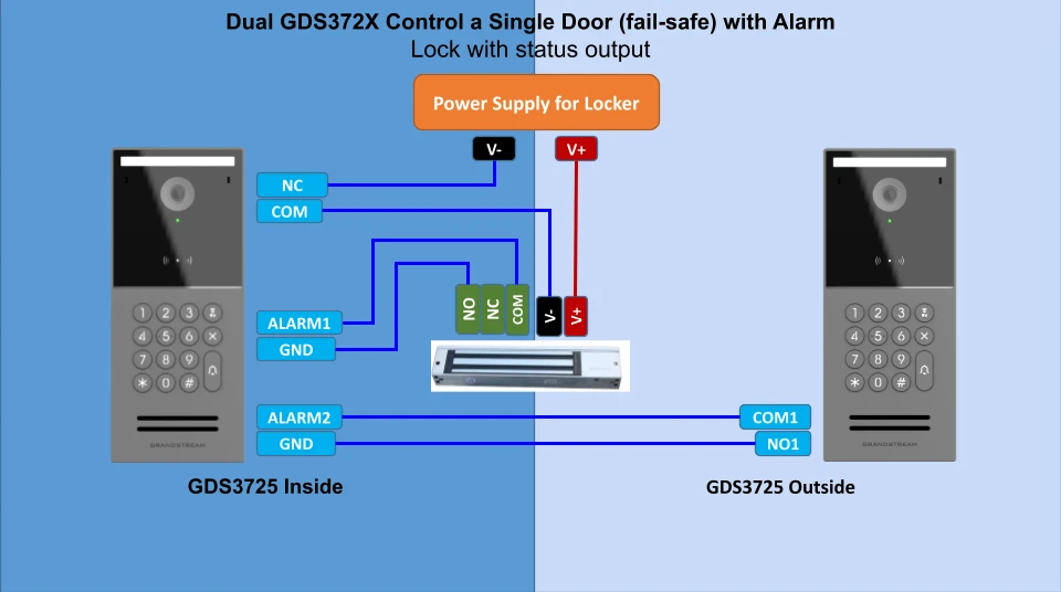
The following wiring diagram illustrates the recommended wiring connections for a fail-safe electric strike deployment. In a fail-safe configuration, the electric strike automatically unlocks when power is lost. Within the Safe Room scenario, this allows the door to open during a power outage, enabling users inside the room to exit safely.
The diagram demonstrates the relay, alarm, and power connections between the GDS372x devices and a fail-safe magnetic strike with status output.
Fail-secure Strike
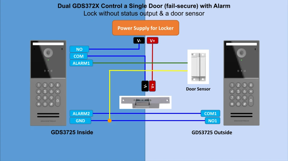
The following wiring diagram illustrates the recommended wiring connections for a fail-secure electric strike deployment. In a fail-secure configuration, the electric strike remains locked when power is lost and unlocks only when power is applied. Within the Safe Room scenario, this allows the door to remain closed during a power outage, maintaining the secured state of the room.
The diagram demonstrates the relay, alarm, and power connections between the GDS372x devices, the fail-secure electric strike, and the door sensor.
GDS372x Interconnection Configuration
After completing the wiring connections, the next step is to configure the Safe Room feature on both the indoor and outdoor units. This configuration ensures proper door control behavior, alarm handling, and accurate room status synchronization between devices.
Indoor Unit
Configure the indoor unit by following the steps below:
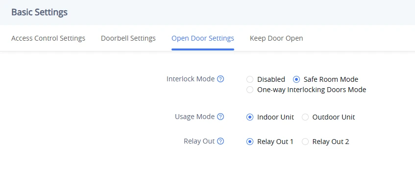
- Navigate to Access Control Settings → Basic Settings → Open Door Settings and set to Interlock Mode.
- Set Usage Mode to Indoor Unit.
- Set Relay Out to the relay output interface used during wiring as shown below.
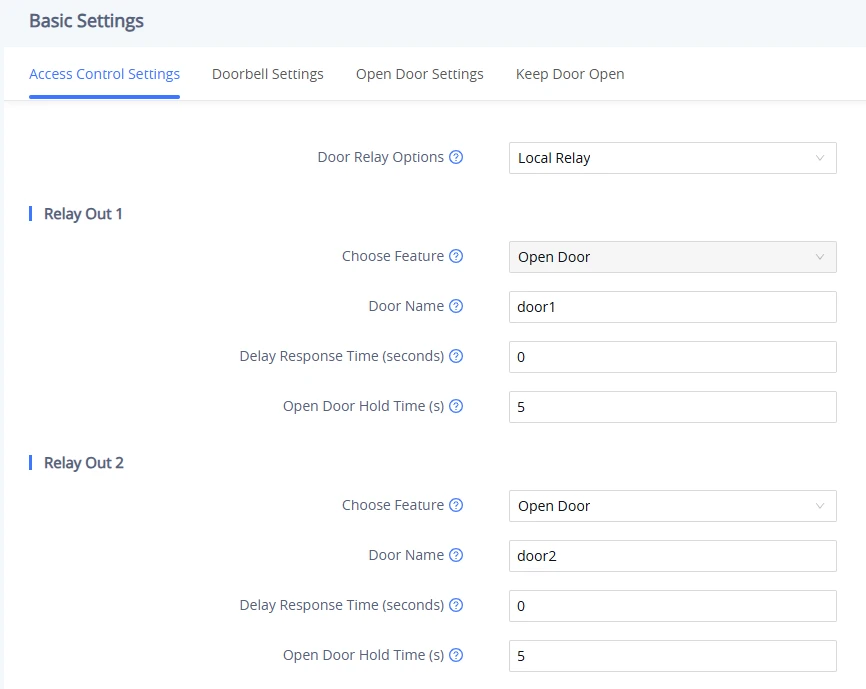
Under Access Control Settings → Basic Settings → Access Control Settings, this relay’s Feature will be automatically set to Open Door.
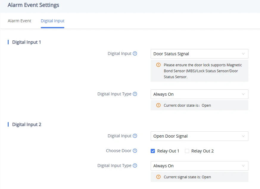
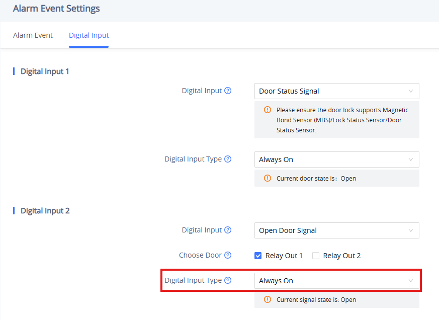
Under Alarm Settings → Alarm Event Settings → Digital Input, Digital Input 1 will be automatically set to Door Status Signal and Digital Input 2 will be set to Door Open Signal.
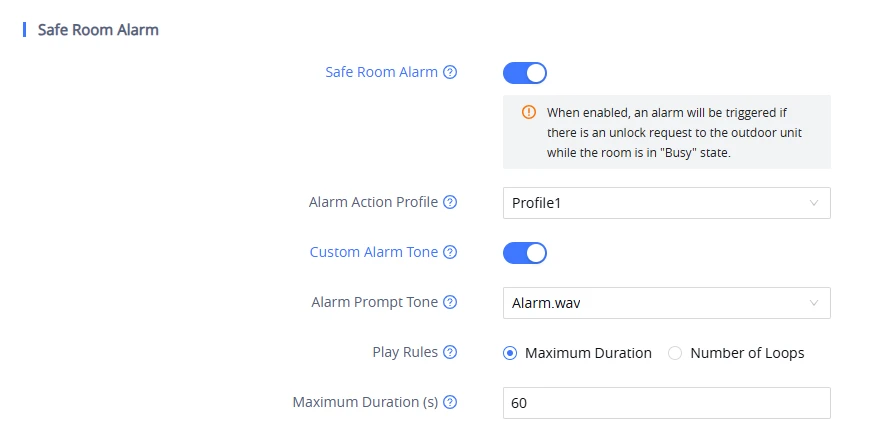
- Navigate to Alarm Settings → Alarm Event Settings → Alarm Event → Safe Room Alarm and press the toggle.
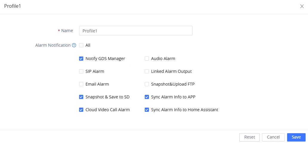
- Select the Alarm Action Profile that will be associated with the alarm; the actions configured in this profile under Alarm Settings → Alarm Action → Alarm Action Profile will be executed when the alarm is triggered.
- Configure a custom Alarm Tone if required to define the audio alert played when the alarm is activated as shown below.
Outdoor Unit
Configure the outdoor unit by following the steps below:
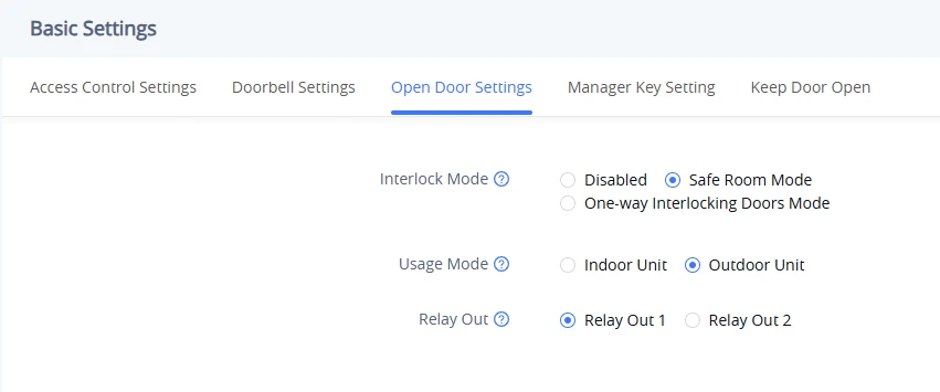
- Navigate to Access Control Settings → Basic Settings → Open Door Settings and set to Interlock Mode.
- Set Usage Mode to Outdoor Unit.
- Set Relay Out to the relay output interface used during wiring as shown below.
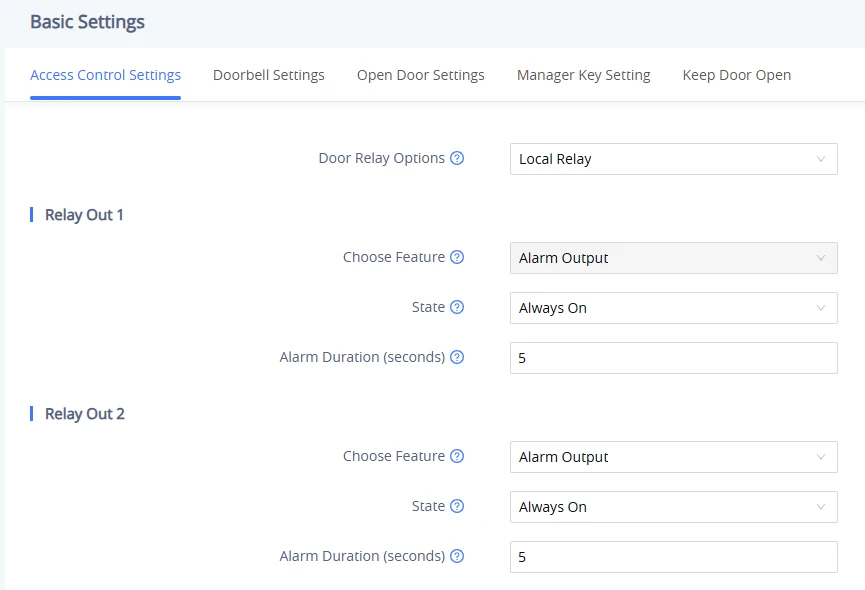
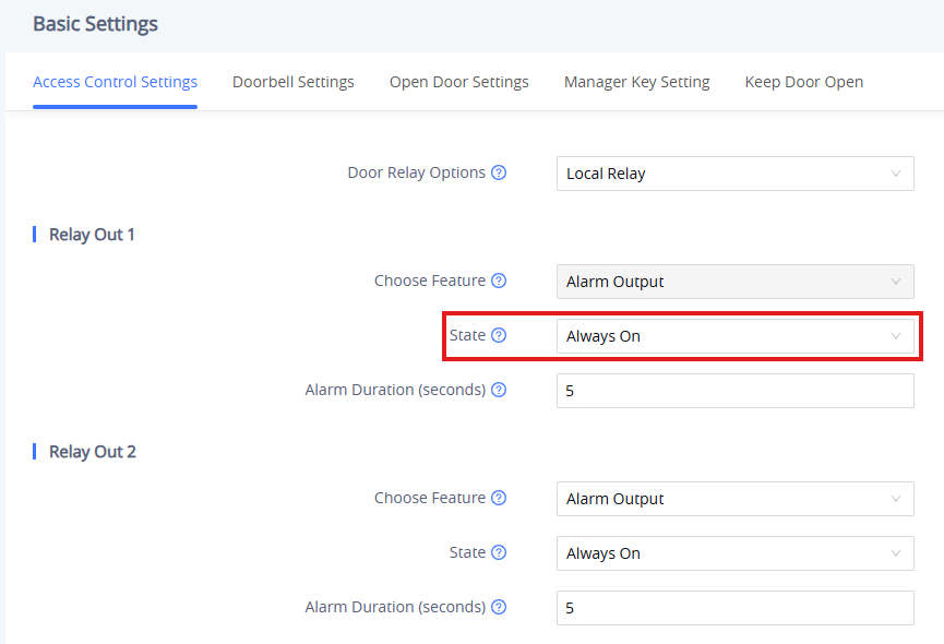
Under Access Control Settings → Basic Settings → Access Control Settings, this relay’s Feature will be automatically set to Alarm Output.
Alarm Action
When the Safe Room Alarm is triggered, the assigned Alarm Action Profile can perform one or more of the following actions:
- Notify GDS Manager: Sends a real-time notification to GDS Manager.
- Audio Alarm: Triggers the built-in audio alarm.
- SIP Alarm: Calls a designated SIP endpoint (e.g., a video intercom).
- Linked Alarm Output: Activates a configured relay or digital output (e.g., a siren).
- Email Alarm: Sends an email notification.
- Snapshot & Upload to FTP: Captures a snapshot and uploads it to a configured FTP server.
- Snapshot & Save to SD: Captures a snapshot and saves it to the device’s SD card.
- Sync Alarm Info to App: Sends the alarm information to the mobile app.
- Cloud Video Call Alarm: When cloud service is enabled, Account 4 (Cloud Account) is automatically used as the callout account.
- Sync Alarm Info to Home Assistant: Sends alarm information to the Home Assistant platform.
Supported Devices
Model | Firmware Version |
GDS3725 | 1.0.3.5 or higher |
GDS3726 | 1.0.3.5 or higher |
GDS3727 | 1.0.3.5 or higher |