


WELCOME
The WP856 is a high-end mobile computing device designed for users on the go who need access to reliable mobile scanning software. This powerful, portable device comes equipped with integrated dual-band 802.11a/b/g/n/ac/ax,2.4G/5G Wi-Fi support, advanced antenna design, roaming support, and integrated Bluetooth for pairing with headsets and mobile devices. With excellent data scanning performance for 1D and 2D barcodes, as well as NFC support for instant data communication, this device helps increase productivity by providing instant access to critical and real-time information. The WP856 is equipped with a 20-hour talk time, a 5.5-inch HD touch screen, and an IP65 dustproof, waterproof, and drop-safe height of 1.5 meters. This device is long-lasting and durable for any environment or user on the go. The WP856 is ideal for deployment scenarios such as healthcare facilities, retail locations, building security, logistics environments, and more.
PRODUCT OVERVIEW
Feature Highlights
The following table contains the major features of the WP856:
 |
|
WP856 Features at a Glance
Technical Specifications
The following table summarizes all the technical specifications, including the protocols/standards supported, voice codecs, telephony features, languages, and upgrade/provisioning settings for the Base station WP856.
Processor | 2.2GHz Octa-core 64-bit processor |
Operating System | Android 13 , Google Mobile Services certified |
Memory | RAM: 4GB ROM: 64GB |
Interface | Type-C 2.0 OTG; Support USB Type-C headset |
Protocol/Standards | SIP RFC3261, TCP/IP/UDP, RTP/RTCP, HTTP/HTTPS,ARP, ICMP, DNS (A record, SRV, NAPTR), DHCP, SSH,TFTP, NTP, STUN, SIMPLE, LDAP, TR-069, 802.1x, TLS, SRTP, IPv6 |
Wi-Fi | Dual-band (2.4GHz and 5GHz) Wi-Fi 6 (IEEE 802.11a/b/g/n/ac/ax) 2.4G supports 20/40MHz bandwidth, 5G supports 20/40/80/160MHz bandwidth |
Voice Codecs and Capabilities | Support for G.711μ /a, G.729A/B, G.722 (wide-band), iLBC, Opus, in-band and out-of-band DTMF (In audio, RFC2833, SIP INFO),VAD, CNG, AEC, PLC,AJB,AGC, ANS |
Video Codecs and Capabilities | H.264 BP/MP/HP, video resolution up to 1080p, frame rate up to 30 FPS, bit rate up to 20Mbps, 3-way video conference (1080p at 30 FPS), anti-flicker capability, auto focus and auto exposure |
Customizable Function Keys | Customizable button for scan, push-to-talk, panic call, and other related functions |
Bluetooth | Yes, Bluetooth 5.2, supports Bluetooth Low Energy (BLE) CMOS (≥5 mil) |
Scanner | 1D: Code128, Code 49, Code 16K, (GS1128) UCC/EAN-128, AIM-128, EAN-8, EAN-13, UPC-E, UPC-A, ITF, ITF 6, ITF 14, Matrix 2 of 5, Industrial 25, Standard 2 of 5, Code39, ISSN, ISBN, CodaBar, Code93, Code 11, Plessey, MSI Plessey, RSS 2D: Aztec, Composite, CS Code, Maxicode, Micro PDF, Micro QR, PDF 417, QR Code, Data Matrix, DotCode. |
Near-Field Communication (NFC) | 13.56MHz RFID ISO14443A/B, ISO15693,ISO18000-3, MIFARE, FeliCa RF, NFC Forum Type 1-4 Tag |
Telephony Features | Hold, transfer, forward, 6-line audio conference, downloadable phonebook (XML, LDAP, up to 1000 items), call waiting, call log (up to 1000 records), auto answer, click-to-dial, flexible dial plan, hot desking, personalized music ring-tones and music on hold, server redundancy and fail-over, push-to-talk |
Security | User and administrator level passwords, MD5 and MD5-sess based authentication, 256-bit AES based secure configuration file, SRTP, TLS, HTTPS, 802.1x media access control |
HD Audio | Yes, both on handset and speakerphone, supports wideband audio |
QoS | 802.11e and Layer 3 (ToS, DiffServ, MPLS) QoS |
Multi-language | English, Arabic, Chinese, Czech, Dutch, German, French, Hebrew, Italian, Japanese, Polish, Portuguese, Russian, Spanish, Turkish, and more |
Upgrade/Provisioning | Firmware upgrade via HTTP/HTTPS, mass provisioning using TR-069 or encrypted XML configuration file, manual upload |
Display | 5.5 inch (1440×720) multi-point capacitive touch screen; Up to 450 NIT (brightness), display backlight adjusts automatically |
Camera | Rear camera: 13MP, auto focus, with LED flashlight Front camera: 5MP, fixed focus |
GPS | Supports GPS, Galilieo, and Beidou |
SD Card | Supports Micro SD cards (up to 256GB) |
AC Adapter | Quick charger (Output: 5V-3A/9V-2A/12V-1.5A Input: AC 100~240V, 50/60Hz) |
Peripherals | Volume button(+,-), Push-To-Talk Button, Left/Right Scan Button, Power button, Vibration motor, Multi-color LED |
Battery | 5000mAh 3.85V rechargeable battery; 200 hours standby time and 20 hours talk time (the battery can be removed and replaced) |
Microphone and Speaker | Dual microphones, HD speaker and speakerphone (1W) |
Sensors | Light & Proximity sensor, accelerometer sensor, gyroscope sensor |
Physical | Headset dimensions: 161x 74 x 15mm Handset weight: 0.28KG |
Temperature and Humidity | Operating Temperature: -20 °C to 50 °C (-4°F to 122°F); Charging Temperature: 5-40 °C (41°F to 104°F); Storage Temperature: -20 °C to 60 °C (-4°F to 140°F); |
Package Contents | Handset unit, power adapter, quick start guide, hand rope, protective shell, 3x plug adapter, Lithium battery, USB cable |
Ruggedization and Protection | Dropsafe up to 1.5m height when dropped on to concrete Casing: IP65-rated waterproof and dustrproof Static Discharge: ±15 kV (air discharge), ±8 kV (direct discharge) |
Compliance | FCC, CE, EAC, IC, RCM |
WP856 Technical Specifications
GETTING STARTED
This chapter provides basic installation instructions, including the packaging contents list and information for obtaining the best performance with the WP856.
Equipment Packaging
WP856 |
|
Equipment Packaging
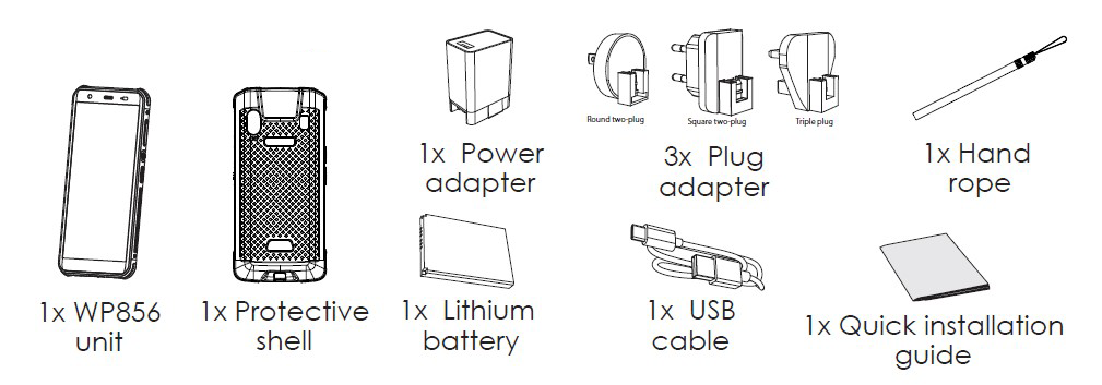
Setting up the WP856
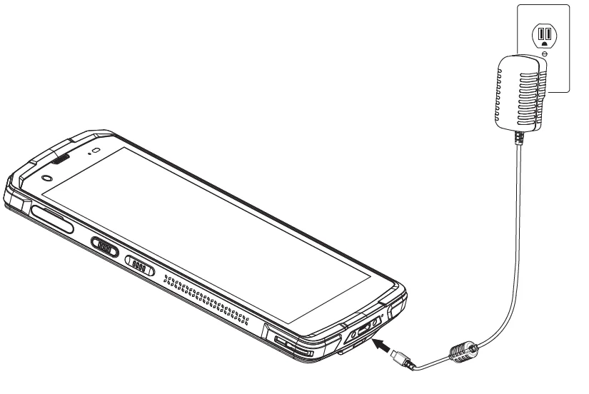
Charging the Battery
Connect the device to a power outlet using the included AC adapter and cable as shown in the figure:
Battery Information
- Technology: Rechargeable Li-ion Battery
- Capacity: 5000mAh
- Standby time: up to 200 hours
- Talk time: up to 20 hours of active talk time
To get the best performance from your WP856, we recommend using the original battery provided in the package. The specifications may differ depending on the age and capacity of the battery used.
WP856 Handset Buttons Description
The WP856 enhances communication and combines usability and scalability in industries such as warehousing, catering, retail, and factory settings. The following screenshot describes the WP856 LCD screen and the main hardware components.
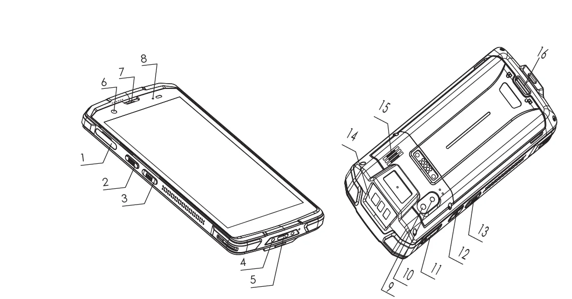
The following table describes the WP856 keypad keys.
Key | Description | |
1 | TF card | Slot for inserting a TF (TransFlash) or microSD card for additional storage. |
2 | PTT Button | Programmable key for quick access to specific functions or applications. |
3 | Left scan key | Button for initiating barcode or QR code scanning. |
4 | Dock connector | Interface for connecting the device to a docking station for charging or data transfer. |
5 | Charging port | Port for connecting a charger to power the device. |
6 | Front camera | Camera located on the front for taking selfies or video calls. |
7 | Earpiece | Speaker for listening to phone calls. |
8 | LED indicator | Light to signal notifications, charging status, or other alerts. |
9 | Camera | Rear camera for taking photos and videos. |
10 | Flashlight | LED light for illumination, used with the rear camera. |
11 | Volume keys | Buttons to increase or decrease the audio volume. |
12 | Power buttom | Button to power on/off the device or wake it from sleep mode. |
13 | Right scan key | Button for initiating barcode or QR code scanning. |
14 | Scan window | The area where the device scans barcodes or QR codes. |
15 | Speaker | Speaker for audio output, such as media playback or speakerphone calls. |
16 | Battery back cover latch | Mechanism to release the back cover to access the battery. |
WP856 LED Status
The WP856 device has the following LED indications:
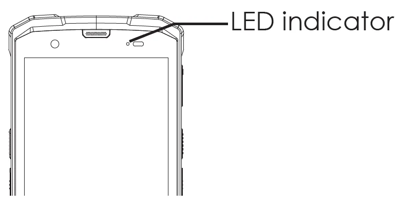
Solid Green | Charged (full) |
Solid Red | Charging (not full) |
Red Blinking | Low battery alarm |
Blue Blinking Once: | Decode successfully |
LED OFF | Normal |
WP856 LED Status
Installing TF Card
The Transfer-Flash (TF) Card is used for additional data storage on the WP856 device. Please follow the steps below for installation:
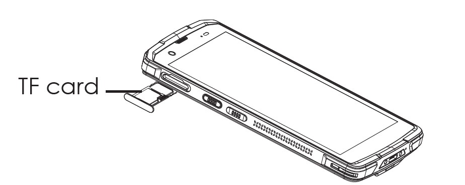
- Find the TF card slot on the left side of the collector/terminal and pull out the cardholder.
- Put the TF card into the cardholder and push the cardholder inside.
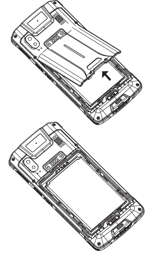
Battery Installation and Removal
Installing the Battery
- Unlock the battery back cover and remove the back cover.
- Attach the top metal contacts of the battery to the metal contacts inside the body and press down firmly.
Removing the Battery
- Press and hold the power button for 2 seconds, then click the shutdown option on the screen, then unlock the battery back cover to open the back cover.
- Remove the battery.
Scanning Barcode
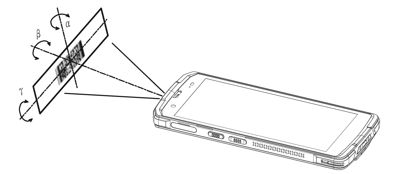
The WP856 mobile computing device allows users to scan 1D and 2D barcodes using an integrated scan window at the top of the phone. It uses NFC technology to scan a barcode using the WP856 device, adjust the scan angle and the distance between the device and the target barcode to make them fall into the following ranges:
- Point the Device’s focus lamp at the center of the barcode.
- Move the Device until you find the appropriate scan distance.
- Optimum scan angles:
- Skew(α)<45° (0° preferably)
- Pitch(γ )<45° (5°- 20° preferably)
- Roll(β)=0° – 360°
Connecting WP856 to a Wi-Fi network
Manual Connection
The WP856 supports dual-band 802.11a/b/g/n/ac/ax Wi-Fi. Please refer to the following steps to connect your WP856 to the Wi-Fi networks:
- On the WP856 touchscreen menu, press the Menu key and navigate to Settings → Network and Internet → Internet.
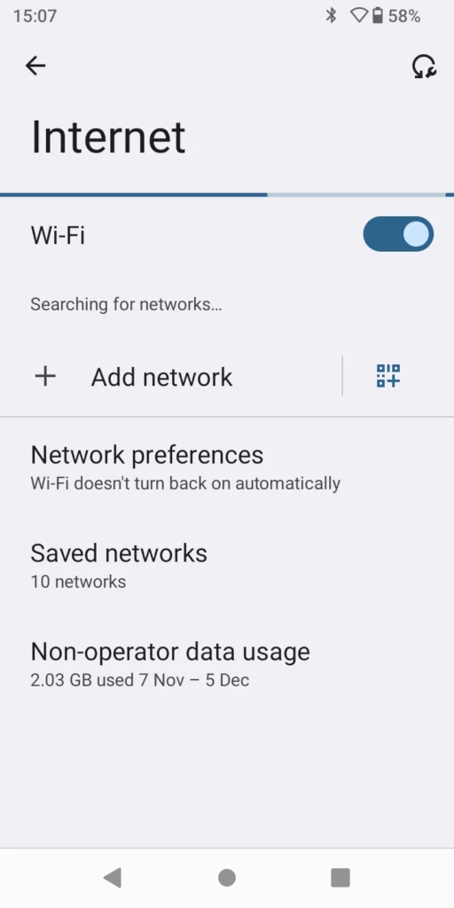
- Set Wi-Fi to “On“ and navigate to “Wi-Fi Settings“. A list of Wi-Fi networks will be displayed.
- Select the desired network to connect to. (Enter the correct password to connect if requested.)
WP856 will display a Wi-Fi icon on the main LCD menu if the connection to the Wi-Fi network is successful.
Wi-Fi Batch Deployment
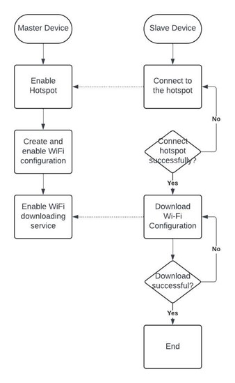
In some scenarios, WP856 can be set as a master device to deploy other units to the Wi-Fi network. This works as follows:
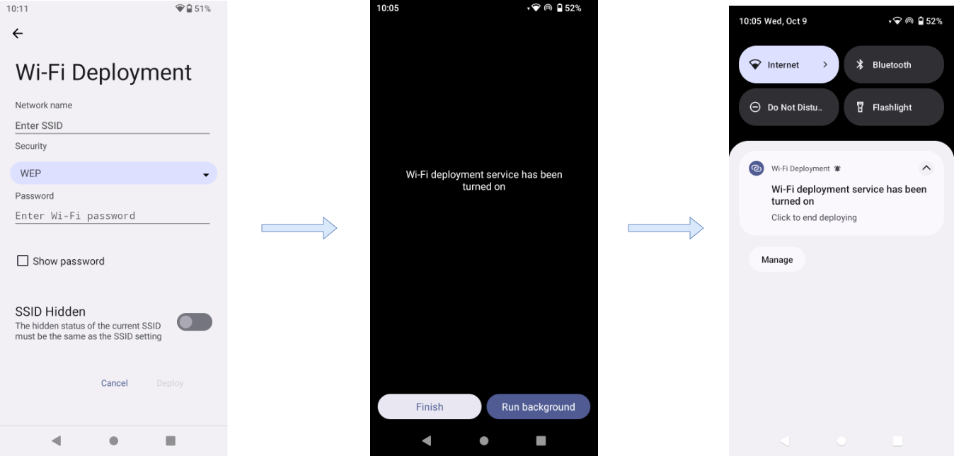
- Enter the key code ( ***800* ) on the dial pad to enter the host mode, in which the device hotspot will be automatically turned on.
- The Master device needs to fill in the Wi-Fi information ( SSID, security, password ), and then start the deployment.
- The Master device will indicate that the Wi-Fi deployment service is enabled and can be used by other devices.
- The Slave devices can connect to the SSID defined on the Master device and connect to the network by dialing the key code ( ***801* ) to enter the slave mode, and they automatically find the hotspot of the master device and establish a connection. Then download the Wi-Fi configuration parameter file, and automatically exit the slave mode after completing the Wi-Fi configuration.
The following flowchart explains the connection process:
Obtain WP856 IP Address
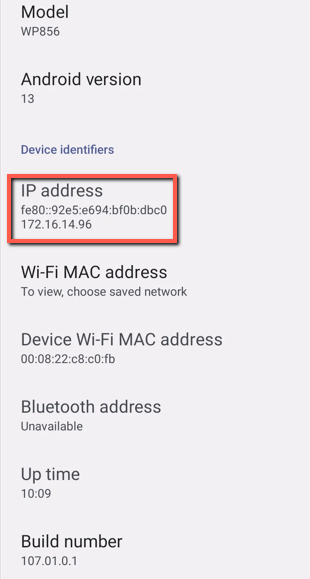
To know which IP address is assigned to your WP856, please follow the steps below:
- After unlocking, sliding the screen up will open the operation menu.
- Go to GsSettings → Device information → Network status to check the IP address assigned to WP856.
- Both the IPv4 and IPv6 addresses of the device will be displayed.
WP856 WEB GUI ACCESS CONFIGURATION
The WP856 can be configured using:
- Web GUI embedded on the WP856 using the PC’s web browser.
- Configuration Menu using the WP856 touchscreen.
Note: From the Web GUI, you can configure all the functions supported by the WP856; while there will be some limitations when configuring the WP856 mobile computing device from the touchscreen.
Configuration via Web Browser
The WP856 embedded Web server responds to HTTP/HTTPS GET/POST requests. Embedded HTML pages allow a user to configure the WP856 through a Web browser such as Google Chrome or Mozilla Firefox.
Note: Please note that Microsoft’s IE 9 and below are not supported, also the records from the web cannot be played with IE10, Edge, and Safari. We highly recommend using Google Chrome or Mozilla Firefox.
Accessing the Web UI
- Access GsSettings → Advanced settings to set “Disable web login” to “No”.
- Go to GsSettings → Device information → Network status to check the IP address assigned to WP856.
- Type the phone’s IP address in your PC browser.
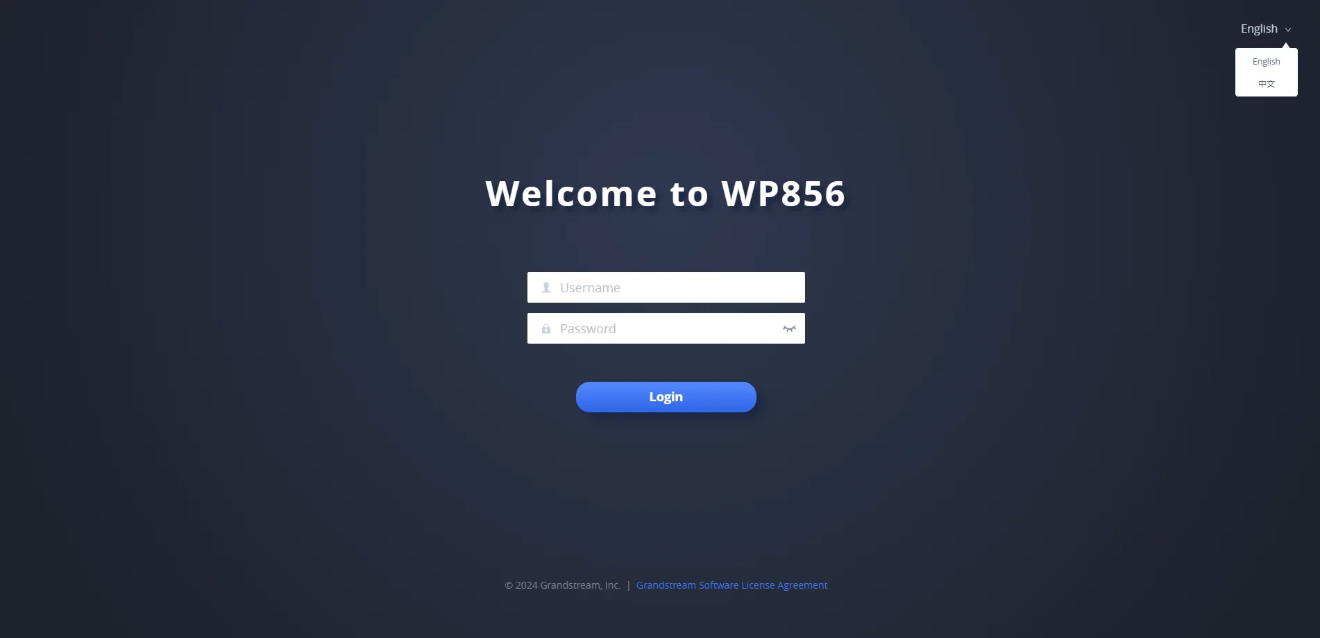
- Enter the admin’s username and password to access the configuration menu. (The factory default username is “admin” and the password is a randomly generated string that is printed on a label in the battery compartment of the device.)
Web GUI Languages
The WP856 web GUI supports English and Chinese languages.
Users can select the displayed language on the web GUI login page or at the upper right of the web GUI after logging in.
Saving the Configuration Changes
When changing any settings, always submit them by pressing the Save and Apply buttons. If using the Save button, after making all the changes, click on the Apply button at the top of the page to submit.
Web UI Access Level Management
There are two default passwords for the login page:
User Level | Username | Password | Web Pages Allowed |
End User Level | user | 123 | Only Status, Phone Settings, Network Settings, System Settings, Application settings, and Maintenance settings with limited access |
Administrator Level | admin | Found on a sticker, on the device | All pages |
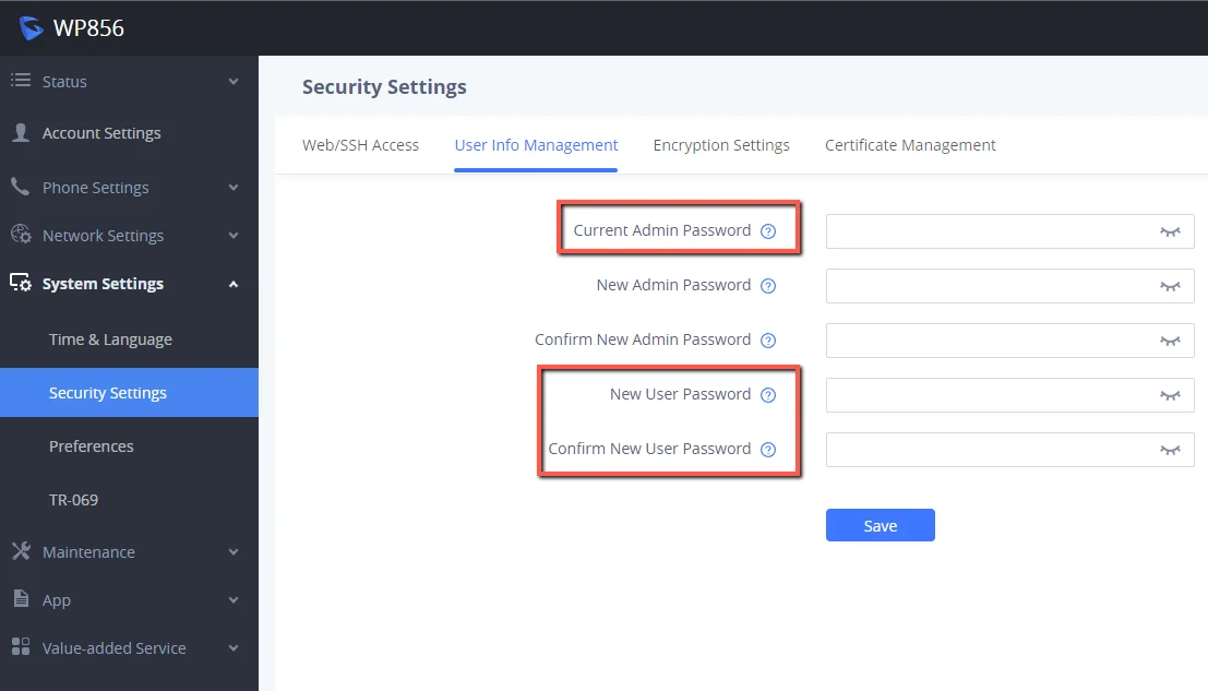
Changing User Level Password
- Access the Web GUI of your WP856 using the admin’s username and password.
- Press Login to access your settings.
- Go to System Settings → Security Settings.
- In User Info Management, locate the user password section:
- Type in the admin password in the Current Admin Password field.
- Type in your new user password in the New User Password field.
- Type in the same password again in the Confirm New User Password field.
- Press the Save and Apply buttons to save your new settings.
Changing Admin Level Password
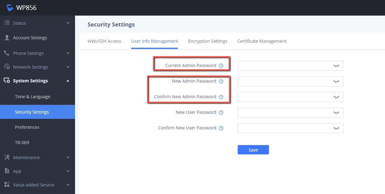
- Access the Web GUI of your WP856 using the admin’s username and password.
- Press Login to access your settings.
- Go to System Settings → Security Settings.
- In User Info Management, locate the admin password section:
- Type in the admin password in the Current Admin Password field
- Type in your new user password in the New Admin Password field.
- Type in the same password again in the Confirm New Admin Password field.
- Press the Save and Apply buttons to save your new settings.
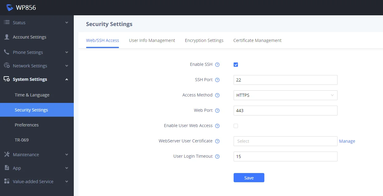
Changing HTTP / HTTPS Web Access Port
- Access the Web GUI of your WP856 using the admin’s username and password.
- Press Login to access your settings.
- Go to System Settings → Security Settings.
- In the Web/SSH Access page, select the access method depending on the desired protocol (HTTP or HTTPS)
- Locate the HTTP / HTTPS Web Port field and change it to your desired/new HTTP / HTTPS port.
- Press the Save and Apply buttons to save your new settings.
WP856 WEB GUI SETTINGS
This section describes the options in the WP856 Web UI. As mentioned, you can log in as an administrator or an end user.
- Status: Displays the Account status, Network status, and System Info of the WP856.
- Account Settings: To configure the SIP account settings and swap account settings.
- Phone Settings: To configure call features, ring tone, audio control, LCD display, multicast paging, etc.
- Network Settings: To configure network settings.
- System Settings: This section configures the features related to the device system settings, such as the Time&Language settings, the security settings…
- Maintenance: To configure web access, upgrading and provisioning, syslog, security settings, etc.
- App: To manage GDS integration and Broadsoft Directories…
Status
Account Status
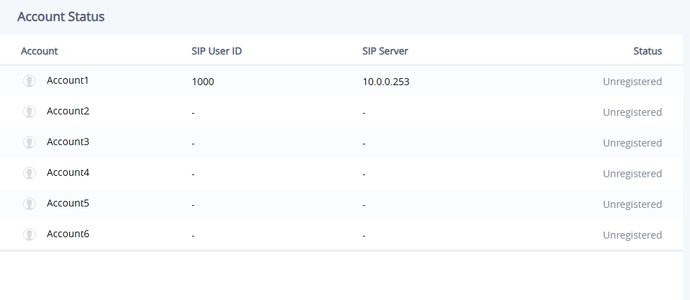
Account | Displays the list of accounts supported by the WP856, the device supports up to 6 accounts |
SIP User ID | Displays the registered SIP user ID. |
SIP Server | Displays the SIP server address |
Status | Shows whether the device is registered or not. |
Network Status
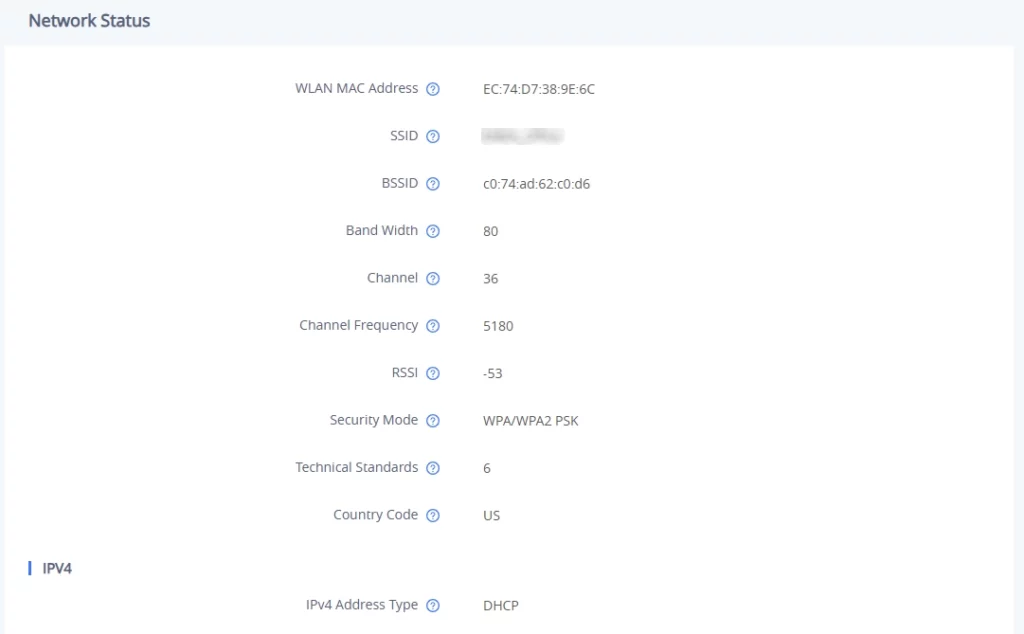
MAC Address | Displays the global unique ID of device, in HEX format. The MAC address will be used for provisioning and can be found on the label coming with original box and on the label located on the back of the device |
NAT Type | Displays the type of NAT connection used by the device. |
IPv4 Address Type | Displays The configured address type: DHCP, Static IP or PPPoE. |
IPv4 Address | Displays The IP address of the device. |
Subnet Mask | Displays Subnet mask of the device. |
Gateway | Displays Default gateway of the device. |
DNS Server 1 | Displays DNS Server 1 of the device. |
DNS Server 2 | Displays DNS Server 2 of the device. |
IPv6 Address Type | Displays The configured address type: DHCP, Static IP. |
IPv6 Address | Displays The IPv6 address obtained on the device. |
IPv6 Gateway | Displays IPv6 gateway of the device. |
IPv6 DNS Server 1 | Displays IPv6 DNS Server 1 of the device. |
IPv6 DNS Server 2 | Displays IPv6 DNS Server 2 of the device. |
System Info
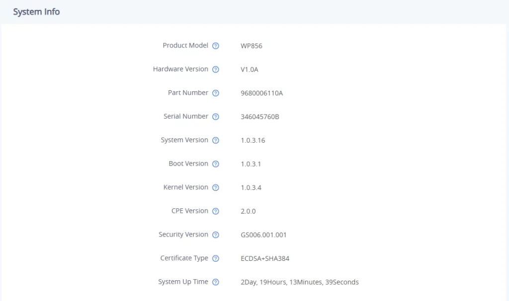
Product Model | Displays the Product model of the device. |
Hardware Version | Displays the Hardware version number. |
Part Number | Displays the Product part number. |
Serial Number | Displays the Product Serial number. |
System Version | Displays the Firmware version. This is the main software release version. |
Boot Version | Displays the Booting code version. |
Kernel Version | Displays the Kernel version |
CPE Version | Displays the CPE Version |
Certificate Type | Displays the certificate type of the device. |
System Up Time | Displays the total running time of the device since last reboot. |
Account
Account x → General Settings | |
Account Registration | |
Account Active | Enables/Disables the SIP Account. |
Account Name | The name associated with each account to be displayed on the LCD. (e.g., MyCompany) |
SIP Server | The URL or IP address, and port of the SIP server. This is provided by your VoIP service provider (e.g., sip.mycompany.com, or IP address) |
Secondary SIP Server | The URL or IP address, and port of the SIP server. This will be used when the primary SIP server fails |
SIP User ID | User account information, provided by your VoIP service provider. |
SIP Authentication ID | SIP service subscriber’s Authenticate ID used for authentication. It can be identical to or different from the SIP User ID. |
SIP Authentication Password | The account password required for the phone to authenticate with the SIP server before the account can be registered. After it is saved, this will appear as hidden for security purpose. |
Display Name | The SIP server subscriber’s name (optional) that will be used for Caller ID display (e.g., John Doe). |
TEL URI | If the phone has an assigned PSTN telephone number, this field should be set to “user=phone”. A “user=phone” parameter will be attached to the Request-URI and “To” header in the SIP request to indicate the E.164 number. If set to “Enable”, “tel:” will be used instead of “sip:” in the SIP request. |
Voice Mail Access Number | Allows users to access voice messages by pressing the MESSAGE button on the phone. This value is usually the VM portal access number. |
Network Settings | |
Outbound Proxy | The IP address or domain name of the main outbound proxy, media gateway, or session border controller. This information is utilized by the device to navigate Firewall or NAT obstacles in various network settings. In the event of detecting a symmetric NAT, STUN becomes ineffective, leaving only an outbound proxy capable of resolving the issue. |
Secondary Outbound Proxy | The IP address or domain name of the Secondary Outbound Proxy, Media Gateway, or Session Border Controller. This secondary outbound proxy comes into play when the primary one encounters a failure. |
DNS Mode | This parameter controls how the Search Appliance looks up IP addresses for hostnames.
|
Max Number Of Sip Request Retries | Sets the maximum number of retries for the device to send requests to the server. In DNS SRV configuration, if the destination address does not respond, all request messages are resent to the same address according to the configured retry times. Valid range: 1-10. |
DNS SRV Failover Mode | Configures the preferred IP mode for DNS SRV. If set to “default”, the first IP from the query result will be applied. If set to “Saved one until DNS TTL”, previous IP will be applied before DNS timeout is reached. If set to “Saved one until no response”, previous IP will be applied even after DNS timeout until it cannot respond.
If the option is set with “default”, it will again try to send register messages to one IP at a time, and the process repeats.
If the option is set with “Saved one until DNS TTL”, it will send register messages to the previously registered IP first. If no response, it will try to send one at a time for each IP. This behavior lasts if DNS TTL (time-to-live) is up.
If the option is set with “Saved one until no responses”, it will send registered messages to the previously registered IP first, but this behavior will persist until the registered server does not respond.
If “Failback follows failback expiration timer” is selected, the device will send all SIP messages to the current failover SIP server or Outbound Proxy until the failback timer expires. |
Failback Expiration (m) | Specifies the duration (in minutes) since failover to the current SIP server or Outbound Proxy before making failback attempts to the primary SIP server or Outbound Proxy. |
Register Before DNS SRV Failover | Configures whether to send REGISTER requests to the failover SIP server or Outbound Proxy before sending INVITE requests in the event of a DNS SRV failover. |
NAT Traversal | Configures whether NAT traversal mechanism is activated. Please refer to user manual for more details. If set to “STUN” and STUN server is configured, the phone will route according to the STUN server. If NAT type is Full Cone, Restricted Cone or Port-Restricted Cone, the phone will try to use public IP addresses and port number in all the SIP&SDP messages. The phone will send empty SDP packet to the SIP server periodically to keep the NAT port open if it is configured to be “Keep-alive”. Configure this to be “No” if an outbound proxy is used. “STUN” cannot be used if the detected NAT is symmetric NAT. Set this to “VPN” if OpenVPN is used. |
Proxy-Require | A SIP Extension to notify the SIP server that the phone is behind a NAT/Firewall. |
Account x → SIP Settings | |
Basic Settings | |
SIP Registration | Selects whether the phone will send SIP Register messages to the proxy/server. The default setting is “Enabled”. |
Unregister Before New Registration |
|
REGISTER Expiration (m) | Specifies the frequency (in minutes) in which the phone refreshes its registration with the specified registrar. The maximum value is 64800 minutes (about 45 days). The default value is 60 minutes. |
SUBSCRIBE Expiration (m) | Specifies the frequency (in minutes) in which the phone refreshes its subscription with the specified registrar. The maximum value is 64800 minutes (about 45 days). The default value is 60 minutes. |
Re-Register before Expiration (s) | Specifies the time frequency (in seconds) that the phone sends re-registration request before the Register Expiration. The default value is 0. |
Registration Retry Wait Time (s) | Specifies the interval to retry registration if the process is failed. The valid range is 1 to 3600. The default value is 20 seconds. |
Add Auth Header on Initial REGISTER | If enabled, the phone will add Authorization header in initial REGISTER request. Default is “Disabled”. |
Enable SIP OPTIONS Keep Alive | Configures whether to enable SIP OPTIONS to track account registration status. If enabled, the phone will send periodic OPTIONS messages to server to track the connection status with the server. Default is “Disabled”. |
SIP OPTIONS Keep Alive Interval (s) | Configures the time interval the phone sends OPTIONS message to the server. If set to 30 seconds, it means the phone will send an OPTIONS message to the server every 30 seconds. |
SIP OPTIONS Keep Alive Maximum Tries | Configures the maximum number of times the phone will try to send OPTIONS message consistently to server without receiving a response. If set to “3”, the phone will send OPTIONS message 3 times. If no response from the server, the phone will re-register. |
SUBSCRIBE for MWI | When set to “Yes”, a SUBSCRIBE for Message Waiting Indication will be sent periodically. The default setting is “No”. |
Use Privacy Header | Configures whether the “Privacy Header” is present in the SIP INVITE message.
The default setting is “default”. |
Use P-Preferred- Identity Header | Configures whether the “P-Preferred-Identity Header” is present in the SIP INVITE message.
|
Use P-Access-Network-Info Header | Configures to use P-Access-Network-Info header in SIP request. Default setting is “Yes”. |
Use P-Emergency-Info Header | Configures to use P-Emergency-Info header in SIP request. Default setting is “Yes”. |
Use P-Asserted-Identity Header | Includes P-Asserted-Identity header in SIP request. |
Use MAC Header |
The default setting is “No”. |
Add MAC in User-Agent |
The default setting is “No”. |
SIP Transport | Selects the network protocol used for the SIP transport. The default setting is “UDP”. |
Local SIP Port | Configures the local SIP port used to listen and transmit. |
SIP URI Scheme when using TLS | Specifies if “sip” or “sips” will be used when TLS/TCP is selected for SIP Transport. The default setting is “sips”. |
Use Actual Ephemeral Port in Contact with TCP/TLS | Configures whether the actual ephemeral port in contact with TCP/TLS will be used when TLS/TCP is selected for SIP Transport. The default setting is “No”. |
Support SIP Instance ID | Configures whether SIP Instance ID is supported or not. The default setting is “Yes”. |
SIP T1 Timeout | SIP T1 Timeout is an estimate of the round-trip time of transactions between a client and server. If no response is received the timeout is increased and request re-transmit retries would continue until a maximum amount of time define by T2. The default setting is 0.5 seconds. |
SIP T2 Timeout | SIP T2 Timeout is the maximum retransmit time of any SIP request messages (excluding the INVITE message). The re-transmitting and doubling of T1 continues until it reaches the T2 value. Default is 4 seconds. |
SIP Timer D Interval | Sets the time interval of SIP Timer D. This timer specifies the wait time of response retransmissions when the client receives 3xx ~ 6xx response to an INVITE. The valid range is 0-64 seconds. If set to 0, the parameter will not take effect. The true time interval is equal to T1*64. |
Remove OBP From Route | Configures to remove outbound proxy from route. If set to “Enabled”, the SIP account will notify the server to remove the proxy in NAT/Firewall environment. If set to “Always”, the SIP account will notify the server to remove the proxy unconditionally. |
Enable 100rel | The use of the PRACK (Provisional Acknowledgment) method enables reliability to SIP provisional responses (1xx series). This is very important in order to support PSTN internetworking. To invoke a reliable provisional response, the 100rel tag is appended to the value of the required header of the initial signaling messages. |
SIP Registration Failure Retry Wait Time upon 403 Forbidden | This parameter sets the wait time before an IP phone retries SIP registration after receiving a 403 Forbidden error, preventing rapid reattempts. |
Session Timer | |
Enable Session Timer | Configures whether to enable session timer function. It enables SIP sessions to be periodically “refreshed” via a SIP request (UPDATE, or re-INVITE). If there is no refresh via an UPDATE or re-INVITE message, the session will be terminated once the session interval expires. If set to “Yes”, the phone will use the related parameters when sending session timer according to “Session Expiration”. If set to “No”, session timer will be disabled. The default setting is “No”. |
Session Expiration (s) | Session Expiration is the time (in seconds) where the session is considered timed out, provided no successful session refresh transaction occurs beforehand. The default setting is 180. The valid range is from 90 to 64800. |
Min-SE (s) | The minimum session expiration (in seconds). The default value is 90 seconds. The valid range is from 90 to 64800. |
UAC Specify Refresher | As a caller, select UAC to use the phone as the refresher, or select UAS to use the callee or proxy server as the refresher. When set to “Omit”, the refresh object is not specified. The default setting is “UAC”. |
UAS Specify Refresher | As a callee, select UAC to use caller or proxy server as the refresher, or select UAS to use the phone as the refresher. The default setting is “UAC”. |
Caller Request Timer | If set to “Yes” and the remote party supports session timers, the phone will use a session timer when it makes outbound calls. The default setting is “No”. |
Callee Request Timer | If set to “Yes” and the remote party supports session timers, the phone will use a session timer when it receives inbound calls. The default setting is “No”. |
Force Timer | If set to “Yes”, the phone will use the Session Timer even if the remote party does not support this feature. Otherwise, Session Timer is enabled only when the remote party supports it. The default setting is “No”. |
Force INVITE | Select “Yes” to force using the INVITE method to refresh the session timer. The default setting is “No”. |
Account x → Codec Settings | |
Preferred Vocoder | |
Preferred Vocoder (Choice 1 – 8) | Multiple vocoder types are supported on the phone, the vocoders in the list is a higher preference. Users can configure vocoders in a preference list that is included with the same preference order in SDP message.
|
Codec Negotiation Priority | Configures the phone to use which codec sequence to negotiate as the callee. When set to “Caller”, the phone negotiates by SDP codec sequence from received SIP Invite. When set to “Callee”, the phone negotiates by audio codec sequence on the phone. The default setting is “Callee”. |
Use First Matching Vocoder in 200OK SDP | When set to “Yes”, the device will use the first matching vocoder in the received 200OK SDP as the codec. The default setting is “No”. |
iLBC Frame Size | Selects iLBC packet frame size. Users can choose from 20ms and 30ms. The default setting is “30ms”. |
G726-32 ITU Payload Type | Payload type for G726-32 in ITU packing mode. Payload 2 remains static, while payload dynamic varies dynamically. |
G.726-32 Dynamic Payload Type | Specifies G726-32 payload type. Valid range is 96 to 126. |
Opus Payload Type | Specifies Opus payload type. Valid range is 96 to 127. It cannot be the same as iLBC or DTMF Payload Type. Default value is 123. |
DTMF | Specifies the mechanism to transmit DTMF digits. There are 3 supported modes:
Default setting is “RFC2833”. |
DTMF Payload Type | Configures the payload type for DTMF using RFC2833. Cannot be the same as iLBC or OPUS payload type. |
Enable Audio RED with FEC | If set to “Yes”, FEC will be enabled for audio call. |
Audio FEC Payload Type | Configures audio FEC payload type. The valid range is from 96 to 126. The default value is 121. |
Audio RED Payload Type | Configures audio RED payload type. The valid range is from 96 to 126. The default value is 124. |
Silence Suppression | If set to “Yes”, when silence is detected, a small quantity of VAD packets (instead of audio packets) will be sent during the period of no talking. For codec G.723 and G.729 only. Default setting is “No”. |
Voice Frames Per TX | Configures the number of voice frames transmitted per packet. It is recommended that the IS limit value of Ethernet packet is 1500 bytes or 120 kbps. When configuring this, it should be noted that the “ptime” value for the SDP will change with different configurations here. This value is related to the codec used in the codec table or negotiate the payload type during the actual call. For example, if set to 2 and the first code is G.729, G.711 or G.726, the “ptime” value in the SDP datagram of the INVITE request is 20 ms. If the “Voice Frame/TX” setting exceeds the maximum allowed value, the phone will use and save the maximum allowed value for the selected first codec. It is recommended to use the default setting provided, and incorrect setting may affect voice quality. The default setting is 2. |
Preferred Video Codec | |
Preferred Video Codec | This parameter allows user to select preferred video codec from the “available” list. The device supports H.264. |
Enable Video FEC | If set to “Yes,” FEC (Forward Error Correction) will be activated for the video call. |
Enable RFC5168 Support | If set to “Yes”, RFC5168 support will be enabled for video call. |
FEC Payload Type | Configures FEC payload type. The valid range is from 96 to 126. |
Packetization Mode | Sets the video packetization mode. If set to “Single NAL Unit Mode”, the packetization mode will be negotiated as single NAL unit mode for video calls and used for video encoding regardles if the other party support the negotiation. If set to “Non-Interleaved Mode”, the packetization mode will be negotiated as Non-interleaved mode for video calls and used for video encoding regardless if the other party supports the negotiation. If set to “Prefer Non-Interleaved Mode”, the packetization mode will prioritize Non-interleaved mode to be negotiated for video calls but if the other party does not support this,the device negotiate “Single NAL Unit Mode”. |
H.264 Image Size | Select the H.264 image size from “720P” , “4CIF”, “VGA”, “CIF” , “QVGA” or “QCIF”. |
Use H.264 Constrained Profiles | Configures whether to use H.264 CBP to establish video call with WebRTC. The function takes effect when H.264 profile setting includes BP type. It is recommended to set to “Yes” when establish video call with WebRTC. |
H.264 Profile Type | Select the H.264 profile type from Baseline Profile, Main Profile, High Profile, or BP/MP/HP. Lower-level profiles are easier to decode, while higher-level profiles provide better compression ratio. Typically, High Profile is recommended for achieving higher video compression ratio. For devices with lower CPU performance, choose Baseline Profile for smoother playback. In high-quality video conferencing scenarios, BP/MP/HP is often used, where all three profiles are negotiated during video decoding to achieve optimal video performance. |
Video Bit Rate | The video bit rate can be adjusted based on the network environment. Increasing the video bit rate may improve video quality if the bandwidth is permitted. If the bandwidth is not permitted than the video quality will decrease due to packet loss. |
SDP Bandwidth Attribute | Select the SDP bandwidth attribute from “Standard” , “Media Level” , “Session Level” or “None”. |
H.264 Payload Type | Enter H.264 codec payload type. The valid range is from 96 to 127. |
Packet Retransmission | When the function is enabled, signaling will carry RTX information, if the final negotiation is successful, the related media RTX function will realize packet loss retransmission purpose. When this function is disabled. then packet loss retransmission cannot be used. |
RTP Settings | |
SRTP Mode | Enable SRTP mode based on your selection from the drop-down menu.
The default setting is “Disabled”. |
SRTP Key Exchange | Selects SRTP key exchange method, the options are:
By Default, the SRTP Key Exchange is set to SDES |
SRTP Key Length | Allows users to specify the length of the SRTP calls. Available options are:
Default setting is AES 128&256 bit |
Enable SRTP Key Life Time | Enable or disable the crypto lifetime when using SRTP. If users set to disable this option, phone does not add the crypto lifetime to SRTP header. The default setting is “Yes”. |
RTCP Keep-Alive Method | Configures the RTCP channel keep-alive packet type.
|
RTP Keep-Alive Method | Configures the RTP channel keep-alive packet type.
|
RTCP Destination | Configures the server address. When there is a call, the RTCP package sent from the device will also be sent to this address. Note: The address should contain port number. |
Symmetric RTP | Configures whether Symmetric RTP is used or not. Symmetric RTP means that the UA uses the same socket/port for sending and receiving the RTP stream. The default setting is “No”. |
RTP IP Filter | Configures whether to filter the received RTP. If set to “Disabled”, the device will receive RTP from any address. If set to “IP Only”, the device will receive RTP from certain IP address in SDP with no port limited. If set to “IP and Port”, the device will only receive RTP from IP address & port in SDP. |
RTP Timeout (s) | Configures the RTP timeout of the phone. If the phone does not receive the RTP packet within the specified RTP time, the call will be automatically disconnected. The default range is 0 and 6-600. If set to 0, the phone will not hang up the call automatically. |
Account x → Call Settings | |
Call Features | |
Start Video Automatically | Configure whether to enable video automatically when auto answering video calls. If set to “No”, video needs to be turned on manually. |
Remote Video Request | Configures the preference of video request handling during an audio call. Users could select “prompt”, “accept” or “deny”. |
Auto-answer | If set to “Yes”, the device will automatically answer incoming calls. If set to “Intercom/Paging Only”, it will answer the call based on the SIP Call-Info or Alert-Info header sent from the server/proxy. |
Play Warning Tone for Auto Answer Intercom | Plays Warning Tone for Auto Answer Intercom |
Intercom Barging | Configures whether to auto answer incoming intercom call when there is already an active call on the phone. When “Intercom Barging” is enabled and the current active call is an intercom call, then the incoming intercom call will be automatically rejected. If the current active call is not an intercom call, then the current active call will be put on hold and the incoming intercom call will be automatically answered. When “Intercom Barging” is disabled, a prompt will be used to indicate the incoming intercom call without interrupting the current active call. |
Auto Preview | Configures whether to turn on video to preview the video of the caller. If set to “Yes”, the user can view the video and hear the caller on the incoming page when there is an incoming call. If set to “Yes with Ringing”, the caller can view the video of the caller and hear the ringtone on the incoming page, but cannot hear the caller. Note: If Auto Answer function has been enabled, this function does not take effect. |
Send Anonymous | If set to “Yes”, the “From” header in outgoing INVITE messages will be set to anonymous. Default is “No”. |
Reject Anonymous Call | If set to “Yes”, anonymous calls will be rejected. The default setting is “No”. |
Call Log | Configures Call Log setting on the phone.
The default setting is “Log All”. |
Enable Call Features | If set to “Yes”, call features (including anonymous call, DND and etc) will be supported locally instead of using the feature code supported on SIP server/proxy. Please refer to user manual for more details. |
Mute on Answer Intercom Call | When enabled, device will mute the incoming intercom call by Call-Info/Alert-Info. |
Transfer On 3-Way Conference Hangup | Defines whether or not the local conference call is transferred to the other parties if the initiator of the conference hangs up. |
Use # as Dial Key | Allows users to configure the “#” key as the “Send” key. If set to “Yes”, the “#” key will immediately dial out the input digits. In this case, this key is essentially equivalent to the “Send” key. If set to “No”, the “#” key is treated as part of the dialed string. |
Use # as Redial Key | Allows users to configure the “#” key as the “Redial” key. If set to “Yes”, the “#” key will immediately redial the last call. In this case, this key is essentially equivalent to the “Redial” key. If set to “No”, the “#” key is treated as part of the dialed string. |
DND Call Feature On | Configuring the DND feature code. When the DND turned on, the feature code will be sent to server, then the server synchronously enables the DND function. |
DND Call Feature Off | Configuring the DND feature code. When the DND turned off, the feature code will be sent to server, then the server synchronously disables the DND function. |
No Key Entry Timeout (s) | This is used to set the time length before dialing the entered digits automatically when no key operation is detected. |
Ring Timeout (s) | Defines the timeout (in seconds) for the rings on no answer. |
Refer-to Use Target Contact | When this feature is enabled, the phone uses the contact address of the target you are transferring the call to, instead of the address provided in the Refer-To header during the call transfer process. |
RFC2543 Hold | If yes, c=0.0.0.0 will be used in INVITE SDP for hold. |
Call Forwarding | |
Call Forwarding | Specifies the Call Forward Type. Select “Disabled” to disable call forward feature. Select “Unconditional” to forward all calls to a particular number. Select “Time based” to set a time range for the call to be forwarded. Or select “Others” to set Call Forward On No Answer and Call Forward On Busy. |
Dial plan | |
Dial Plan Prefix | Configures a prefix added to all numbers when making outbound calls. |
Disable Dialplan | Defines whether to disable dial plan of the Dial Page, Contacts, Incoming Call History, Outgoing Call History, Programmable Key & Click2Dial functions. If set to “Yes”, the corresponding dial plan of the function will be disabled. |
Dial Plan | Configures the dial plan rule. For syntax and examples, please refer to user manual for more details. Dial Plan Rules:
Allow 311, 611, and 911 or any 11 digit numbers with leading digits 1617;
Block any number of leading digits 1900 or add prefix 1617 for any dialed 7 digit numbers;
Allows any number with leading digit 1 followed by a 3-digit number, followed by any number between 2 and 9, followed by any 7-digit number OR Allows any length of numbers with leading digit 2, replacing the 2 with 011 when dialed.
Explanation of example rule (reading from left to right):
Note: In some cases, where the user wishes to dial strings such as *123 to activate voice mail or other applications provided by their service provider, the * should be predefined inside the dial plan feature. An example dial plan will be: { *x+ } which allows the user to dial * followed by any length of numbers. Max length of dial plan is up to 1024 characters. |
Caller IDs | |
Caller ID Display | When set to “Auto”, the phone will look for the caller ID in the order of P-Asserted Identity Header, Remote-Party-ID Header and From Header in the incoming SIP INVITE. When set to “Disabled”, all incoming calls are displayed with “Unavailable”. |
Callee ID Display | When set to “Auto”, the phone will update the callee ID in the order of P-Asserted Identity Header, Remote-Party-ID Header and To Header in the 180 Ringing. When set to “Disabled”, callee id will be displayed as “Unavailable”. When set to “To Header”, caller id will not be updated and displayed as To Header. |
Ringtone | |
Account RingTone | Allows users to configure the ringtone for the account. Users can choose from different ringtones from the dropdown menu. Note: User can also choose silent ring tone or doorbell. |
Ignore Alert-Info header | Configures to play default ringtone by ignoring Alert-Info header. The default setting is “No”. |
Match Incoming Caller ID | Specifies matching rules with number, pattern, or Alert Info text (up to 10 matching rules). When the incoming caller ID or Alert Info matches the rule, the phone will ring with selected distinctive ringtone. Matching rules:
xx+ : at least 2-digit number. xx : only 2-digit number. [345]xx: 3-digit number with the leading digit of 3, 4 or 5. [6-9]xx: 3-digit number with the leading digit from 6 to 9.
Users could configure the matching rule as certain text (e.g., priority) and select the custom ring tone mapped to it. The custom ring tone will be used if the phone receives SIP INVITE with Alert-Info header in the following format: Alert-Info: <http://127.0.0.1>; info=priority When the incoming caller ID or Alert Info matches one of the 10 rules, the phone will ring with the associated ringtone. Note: Beginning with firmware version 1.0.3.98, a new feature was introduced that enables the use of a ringtone stream via a remote URL. The functionality of this feature works as follows: the following audio file named test.wav is uploaded onto an HTTP server and the remote URL is “http://192.168.5.165:8080/test.wav;info=ring3”, the IP phone then attempts to use the provided URL first to play the ringtone. If the URL is not functional for some reason, it will then use the info=ring3 parameter, as the default ringtone. |
Account x → Advanced Settings | |
Security Settings | |
Check Domain Certificates | Configures whether the domain certificates will be checked when TLS/TCP is used for SIP Transport. The default setting is “No”. |
Trusted Domain Name List | Fill in the list of trusted domain names, which supports filling in the SAN list used only for domain name verification in TLS to obtain certificates. If it matches any item in the trusted domain name list, the certificate is trusted. By default, the remote proxy domain name and SIP server domain name are trusted.Supports filling in numbers/letters/-/./*, Support setting wildcard domain names, such as “*.grandstream.com”, and trust any domains that end with “.gradstream.com”. |
Validate Certificate Chain | Validates CA certificate when TLS/TCP is configured for SIP. |
SIP CA Certificate | Select the CA certificate for server verification. |
SIP User Certificate | Select the user certificate to access SIP TLS authentication content required by some specific servers. If the private key is included, upload it with the user certificate. |
Validate Incoming SIP Messages | Defines whether the incoming SIP messages will be validated or not. |
Allow Unsolicited REFER | The “Allow Unsolicited REFER” option allows the handset to accept, deny, or require authentification for external REFER requests coming from the SIP server, these requests automatically transfer calls to other parties without user intervention, the available options are:
The default value is Disabled. |
Accept Incoming SIP from Proxy Only | When set to “Yes”, the SIP address of the request URL in the incoming SIP message will be checked. If it doesn’t match the SIP server address of the account, the request will be rejected. |
Check SIP User ID for Incoming INVITE | If set to “Yes”, SIP User ID will be checked in the Request URI of the incoming INVITE. If it doesn’t match the device’s SIP User ID, the call will be rejected. |
Allow SIP Reset | Allow SIP Notification message to perform factory reset. The default setting is “No”. |
Authenticate Incoming INVITE | If set to “Yes”, the phone will challenge the incoming INVITE for authentication with SIP 401 Unauthorized response. The default setting is “No”. |
SIP Realm Used for Challenge INVITE & NOTIFY | Configure this option to set the SIP server used to validate incoming INVITE or NOTIFY (for check-sync, resync, reboot). Only takes effect when Authenticate Incoming INVITE or SIP NOTIFY Authentication is enabled. |
MOH | |
Upload Local MOH Audio File | Configures to play reminder tone when the call is on hold. Click BROWSE to upload audio file from PC. The MOH audio file should be “.wav” or “.mp3” format. It may take a long time uploading and processing the file, please be patient. |
Enable Local MOH | If set to “Yes” , the local MOH will be enabled. Users need to upload local MOH audio file. Once enabled, users could play the file when holding the call. |
Advanced Features | |
Special Feature | Different soft switch vendors have special requirements. Therefore users may need select special features to meet these requirements. Users can choose from Standard, CBCOM, RNK, China Mobile, ZTE IMS, Mobotix, ZTE NGN, or Huawei IMS depending on the server type. |
Feature Key Synchronization | This feature is used for BroadSoft or Metaswitch call feature synchronization. When set to “BroadSoft/Metaswitch”, DND and Call Forward features can be synchronized with the server. The local call forward function are disabled when this feature is active. |
Conference URI | Refers to the Uniform Resource Identifier used for initiating or joining a conference call or a multi-party call session. This URI is predefined by the system or the conference server and is used by the WP856 to route conference call requests to the appropriate conferencing server. |
Allow Sync Phonebook Via SIP Notify | If set to “Yes”, the device will allow SIP NOTIFY messages to sync local phonebook. |
SCA | |
Enable SCA (Shared Call Appearance) | If enabled, Shared Call Appearance (BroadSoft standard) feature will be applied to the registered account. |
Enable Barge-in | If enabled, users can barge into an active call on a shared line. |
Line-seize Timeout (s) | Configures the interval (in seconds) when the line seize is considered timed out when Shared Line feature is used. The valid range is: 15-60. The default value is 15 seconds. |
Call Park | |
BroadSoft Call Park | If enabled, phone will send SUBSCRIBE to BroadSoft server to obtain Call Park notifications. |
Call Park Feature Code | Configures the feature access code to park current call on a parking lot or another extension. |
Auto-filling Call Park Retrieve Feature Code | If enabled, the Call Park Retrieve feature code will be automatically filled in the dialing interface during call pickup. Default value is “Enable”. |
Call Park Retrieve Feature Code | Configure the feature access code for retrieving the parked call on the account or BLF keys. |
Account Settings Page Definitions
Phone Settings Page Definitions
General Settings
Basic Settings | |
Local RTP Port | Defines the Local RTP port used. |
Use Random Port | When set to “Yes”, this parameter will force random generation of both the local SIP and RTP ports. This is usually necessary when multiple devices are behind the same full cone NAT. (This parameter must be set to “No” for Direct IP incoming calls, but IP outgoing calls are not affected) |
Enable In-call DTMF Display | Enables DTMF display when in-call. |
Enable LDAP Timeout Auto Search | Configures whether to display the matched content automatically in LDAP search when timeout. If set to “No”, users need to click the Search button to search the matched contacts mentioned above. |
Keep-alive Interval (s) | Specifies how often the device sends a blank UDP packet to the SIP server in order to keep the “pin hole” on the NAT router to open. |
STUN Server | The IP address or domain name of the STUN server. STUN resolution results are displayed in the STATUS page of the device Web GUI. Only non-symmetric NAT routers work with STUN. |
Use NAT IP | The NAT IP address in SIP/SDP messages. This field is blank by default settings. You should ONLY use it when required by your ITSP. |
Guest Features | |
Guest Login | This feature allows the user to register SIP account as a guest. The guest can enter the user ID, password, and PIN, to ensure the validation and account information. Enable/disable guest login. Users should configure SIP domain name when using this function. Users should input SIP user name and password on LCD after rebooting the phone. |
Guest Login PIN Code | When set “Guest Login” option to “Yes” and “Guest Login Timeout” to “Never”, users should input the PIN code to login. |
Server Alias | The server alias is used to customize the server name. |
Server List | This is the list of SIP domain names under the selected severs. The registration priority of addresses in the list is from top to bottom. Up to 2 SIP domains are supported. |
Call Settings
Call Features | |
Enable Video Call | Enables the video call feature. |
Enable Direct IP Call Mode | Configures enable/disable direct IP call mode of the device. If set to “Yes”, the feature of direct IP call will be enabled. |
Enable Paging Call Mode | Configures enable/disable paging call mode of the device. If set to “Yes”, the feature of paging call will be enabled. |
Enable Call Waiting | Enables the call waiting feature. |
Enable Call Waiting Tone | Enables the call waiting tone when call waiting is on. |
Enable Transfer | Enables the Transfer function. |
Hold Call Before Completing Transfer | If you choose “Yes”, the transfer call status will be kept as hold status after Attended transfer operation. |
Enable Transfer Via Non-Transfer Programmable Key | Programmable Key with type Speed dial, BLF and Speed dial via active account will perform as transfer programmable keys under active call. The transfer mode during the call depends on the “Default Transfer Mode” mentioned above, and can also be selected on the transfer interface, but the transfer mode for incoming calls only supports blind transfer. |
Auto Unhold on Line Key Press | Configures when there are multiple lines, whether to resume the line automatically when clicking the line on hold, and hold the line in the primary call. Note: if this is a manually hold operation rather than hold from switching lines, the call will not be resumed automatically. |
Record Mode | Configures recording mode. If set to “Record locally”, the device will use the local recorder for call recording, and the audio file will be saved according to the recorder setup. If set to “Record on UCM”, the device will send the recording feature code to the UCM server to request for recording, and the recording function will be executed by the server. |
Enable Auto Record When Call Established | Configures whether to auto record when a call is established. If set to “Yes”, the call recording will start automatically when the call is established. |
Enable Noise Block | Configures whether to enable noise block feature. If enabled, all the background noise will be effectively blocked during the call. |
Enable Local In-call DTMF Tone in Speaker Mode | When using the speaker channel in call, enable the playback effect of the local DTMF sound. |
Enable Headset Noise Shield | Select the appropriate shield level based on the TX loudness of the earphone. The higher the selected shield level, the more environmental noise will be reduced in the transmitted audio, but the more likely it will affect sound quality.
The default setting is set to Disabled. |
Enable Handset Noise Shield 2.0 | When enabled, the remote party will hear less environmental noise during a call. If set to “High Shield”, most of the environmental noise can be shielded. If set to “Moderate Shield”, some comfortable environmental noise will remain for the remote party.
The default setting is set to High Shield. |
Noise Suppression Mode | Configure the noise suppression mode for the TX direction. Classic noise suppression can shield the smooth noise in the environment, while AI noise suppression can shield the smooth noise in the environment and eliminate sudden noise at the same time.
|
Incoming/Outgoing Call | |
Auto Mute on Entry | Configures whether to mute the call on entry automatically. If set to “Disabled”, then do not use auto mute function. If set to “Auto Mute on Outgoing Call”, then mute automatically when the other party answers the outgoing call. If set to “Auto Mute on Incoming Call”, then mute automatically when answering the incoming call. If set to “Mute on Incoming & Outgoing Call”, then mute automatically when the call is established. Note: This function only takes effect when the device is changed from the idle status to call status. Users could click the Mute button on call interface to cancel the current mute status. |
Rejected Call Notification | Specify whether to enable rejected call notification. Once enabled, a missed call will prompt on LCD when reject the incoming call. |
Special Function for Incoming Call | Defines the function for the incoming call. |
Enable Conference | Enables the Conference function. |
Auto Conference | If enabled and the user clicks “Conference ” or “Invite” (in conference) button and there exists more than 1 line but less than 6 lines, the phone will put all lines into the conference room for multi-party conference call; If the current lines are more than 6, the phone will access line selection interface, the user needs to manually choose the line before making a conference call. |
Hold Call Before Adding Conferee | Configures whether to place the current call on hold before adding new member(s) to a conference. If enabled, the current call will be put on hold when the host presses Conference or Add key to invite new member(s). When an invited member answers the call and agrees to attend the conference, the host needs to manually resume the conference with the new member added. If disabled, the current call will not be put on hold and the invited member will join the meeting automatically after answering the call. |
Return Code When Refusing Incoming Call | When refusing the incoming call, the phone will send the selected type of SIP message of the call.
|
DND Settings | |
DND Mode | Enables/Disables DND mode on the phone. |
Enable DND Reminder Ring | If enabled, the phone will play a sound when it is set to DND mode. Disabled by default. |
Return Code When Enable DND | When DND is enabled, the device will send the selected type of SIP message. |
Advanced Settings | |
Filter Characters | Filter Characters are used to filter the specific separator characters for Click2Dial or contacts imported from other devices. These specific characters are not part of the actual phone number and needed to filter out. Users could set up multiple characters. For example, if set to “[()-]”, when dialing (0571)-8800-8888, the character “()-” will be automatically filtered and dial 057188008888 directly. Initiate calls from other places except dial screen, such as call history and contacts, will automatically filter the characters. Dialing out from Dial screen will not filter any characters. |
Escape ‘#’ as %23 in SIP URI | Replaces ‘#’ by ‘%23’ in some special situations. |
Ringtone
Auto Config CPT by Region | If set to “Yes”, the phone will configure CPT (Call Progress Tone) according to different regions automatically. If set to “No”, you can manually configure CPT parameters. |
Ringback Tone | Configures tone frequencies based on parameters from the local telecom provider. By default, they are set to the North American standard. Frequencies should be configured with known values to avoid uncomfortable high pitch sounds. |
Busy Tone | |
Reorder Tone | |
Call Waiting Tone | |
Call Waiting Tone Gain | This configures the call waiting tone gain. By default, they are set to the North American standard. Users could adjust the tone frequencies based on parameters from the local telecom provider. Users could select “Low”, “Medium” or “High”. |
Default Ring Cadence | The ringing pattern heard by the dialer before the called party picks up the call. |
Video Settings
Video Frame Rate | The video frame rate is adjustable based on network condition. Increasing the frame rate will significantly increase the amount of data transmitted, therefore consuming more bandwidth. The video quality will deteriorate due to packet loss if extra bandwidth is not allocated.
|
Video Display Mode | Set the video display mode to “Original proportion”, “Equal proportional cutting” or “Proportional add black edge”. If set to “Original proportion”, the device displays video in its original proportion that received from remote party, if the remote video display proportion is different from the device, the device will stretch or compress video to display it; If set to “Equal proportional cutting”, the device will cut video to meet its own display proportion; If set to “Proportional add black edge”, the device will display video in its original proportion, if still exists spare space, the device will add black edge on it. |
Enable Frame Skipping in Video Decoder | If set to default setting “Yes”, the device will skip the P frame in lost video packet to decode the I frame in the next video packet. This setting helps to reduce video distortion. |
Default Video Stream | Select the default video stream enabled during video calls.
|
PTT/Paging
General Settings | |
Allow PTT/Paging When Phone Is Locked | If set to “Yes”, the device can initiate an PTT/Paging in the lock screen status. Set to “No” by default |
IGMP Keep-Alive Interval (s) | Specifies how often the phone report IGMP when PTT/ Paging function is turned on. IGMP reporter help to keep PTT/ Paging receivable in dormant state. The interval may take some effect to standby time. Disabled value is 30 seconds |
PTT/Group Paging | |
PTT/Group Paging Address | Set the PTT/Group Paging address. |
Port | Set port number for PTT/Group paging Address. |
Emergency Channel Volume | Set default volume for PTT/paging when emergency channel/group is used. the range is from 1-7 |
PTT Config | |
PTT | Configures to enable or disable PTT. |
Default Channel | Set default channel for PTT. When presing and holding the PTT button, PTT will be initiated using the default channel. |
Priority Channel | Set priority channel for PTT. PTT received on priority channel will take precedence over active PTT on normal channel. |
Emergency Channel | Set emergency channel for PTT. Emergency channel has the highest priority. PTT using emergency channel will take precedence over PTT on priority or normal channel. Please note PTT to emergency channel will not be rejected even when device has enabled DND. |
Accept While Busy | Configures whether to accept PTT while device is in active call. If set to “No”, device will ignore PTT while in active call. If set to “Yes”, while in active PTT talk, device will accept PTT if it has the same priority; If device is in active SIP call, device will accept PTT and put the SIP call on hold. Disabled by default |
Caller ID | Set Caller ID displayed on the call interface during a PTT call. |
PTime (ms) | Set payload size for PTT. |
Audio Codec | Set audio codec for PTT. |
Channel | Set PTT channel. Users can configure whether to use the channel for transmit, subscribe, join PTT and its label. Only available and joined channel will be displayed in PTT channel list. If users need send or receive PTT, “Transmit” and “Subscribe” must be enabled for this channel. |
Paging Config | |
Group Paging | Configures to enable or disable group paging. |
Default Group | Set default paging group. When pressing and holding the PTT button, paging will be initiated using the default group. |
Priority Group | Configures priority paging group. Paging received on priority group will take precedence over active paging on normal group. |
Emergency Group | Set emergency group for paging. Emergency group has the highest priority. Paging using emergency group will take precedence over paging on priority or normal group. |
Accept While Busy | Configures whether to accept paging while device is in active call. If set to “No”, device will ignore paging while in active call. If set to “Yes”, while in active paging call, the device will accept other paging calls if it has the same priority. If device is in an active SIP call, device will accept paging and hang up the SIP call. |
Caller ID | Set Caller ID displayed on the call interface during paging. Default is “channel(*)” |
PTime (ms) | Set payload size for paging. |
Audio Codec | Set audio codec for paging. |
Group | Configures paging group. Users can configure whether to use the group to accept and join group, and its label. Only available and joined group will be displayed in paging group list. If users need receive paging, “Subscribe” must be enabled for this group. |
Multicast Paging | |
Paging Priority Active | If enabled, during a multicast page if another multicast is received with higher priority (1 being the highest) that one will be played instead. Enabled by Default. |
Paging Barge | During an active call if incoming multicast page has higher priority (1 being the highest) than this value, the call will be held and multicast page will be played. |
Multicast Paging Codec | The codec for sending multicast pages. |
Multicast Paging Function | Enable or disable multicast paging. Disabled by Default |
Multicast Paging Address | Configure the listening address and channel name of multicast paging. You can configure up to 10 Listening Addresses |
Account Disaster Recovery
Main Account | |
Main Account | Configures the main account into account disaster recovery group. Each account can only be selected once. |
SIP Server | The URL or IP address, and port of the SIP server. This is provided by your VoIP service provider (ITSP). |
SIP User ID | User account information, provided by your VoIP service provider (ITSP). It’s usually in the form of digits similar to phone number or actually a phone number. |
SIP Authentication ID | SIP service subscriber’s ID used for authentication. It can be identical to or different from the SIP User ID. |
SIP Authentication Password | The account password required for the phone to authenticate with the ITSP (SIP) server before the account can be registered. After it is saved, this will appear as hidden for security purpose. |
Outbound Proxy | IP address or domain name of the primary outbound proxy, media gateway, or session border controller. It’s used by the device for Firewall or NAT penetration in different network environments. If a symmetric NAT is detected, STUN will not work and ONLY an outbound proxy can provide a solution. |
Backup Account 1 | |
Backup Account | If the outgoing/incoming call fails when using main account, the phone will try to use other backup accounts in the same group. Each account can only be selected once. |
SIP Server | The URL or IP address, and port of the SIP server. This is provided by your VoIP service provider (ITSP). |
Outbound Proxy | IP address or domain name of the primary outbound proxy, media gateway, or session border controller. It’s used by the device for Firewall or NAT penetration in different network environments. If a symmetric NAT is detected, STUN will not work and ONLY an outbound proxy can provide a solution. |
Network Settings Page Definitions
Bluetooth
Device Name | Display name when paired with other devices. |
Bluetooth | Enables/Disables the Bluetooth function. |
Bluetooth Devices | Scan available Bluetooth devices for pairing. After enabling the Bluetooth function, the device will automatically scan for available Bluetooth devices. |
Wi-Fi Settings
Wi-Fi Basics | |
IP Mode | Selects which Internet protocol to use. When both IPv4 and IPv6 are enabled, device attempts to use preferred protocol first and switches to the other choice if it fails. |
Wi-Fi Signal Warning | When the Wi-Fi signal strength is lower than the threshold set by this level, the device will display a warning. Disabled by default |
Wi-Fi Function | This parameter enables/disables the Wi-Fi function. The default setting is set to “No”. |
Wi-Fi Band | Sets the type of WiFi Band. The default setting is 2.4G&5G. |
ESSID | This parameter sets the ESSID for the Wireless network. Press “Scan” to scan for the available wireless network. |
Add Network | |
ESSID | Enter the name of hidden ESSID. |
Security Mode for Hidden SSID | This parameter defines the security mode used for the wireless network when the SSID is hidden, the options are: None, WEP, or WPA/WPA2 PSK |
Password | Configures the hidden ESSID password. |
Advanced Settings | |
Host Name (option 12) | Specifies the name of the client. This field is optional but may be required by some Internet Service Providers. |
Vendor Class ID (option 60) | Used by clients and servers to exchange vendor class ID. |
WiFi Roaming | |
WiFi Roaming Mode | Set the WiFi roaming mode. The default mode is suitable for regular scenarios and has a strong battery life; Boost mode is suitable for scenarios where you need to move around a lot; Fast roaming mode supports 802.11k, 802.11v, 802.11r; Custom mode requires you to manually enter the value yourself. |
Signal Threshold | Sets the WiFi signal threshold. When the WiFi signal strength of the device drops below this value, the device will scan for a hotspot above the threshold value and connect to it. |
Roaming Gain (dB) | Sets the minimum signal gap of roaming between different APs. When the signal strength difference between the scanned AP and the current is greater than this value, roaming will be triggered. |
Good Signal Scanning Interval (s) | Sets the time interval for signal scanning when the WiFi signal strength is higher than the signal threshold. |
Poor Signal Scanning Interval (s) | Sets the time interval for signal scanning when the WiFi signal strength is lower than the signal threshold and there is no hotspot which is higher than the current signal strength. |
802.11r | Enables faster handoff between Wi-Fi access points by pre-authenticating, reducing interruptions during roaming, ideal for VoIP and video calls. |
802.11v | Improves Wi-Fi efficiency by helping devices select better access points and manage power usage, optimizing performance and battery life. |
Advanced Settings
Preferred DNS 1 | Configures the preferred DNS 1 address. |
Preferred DNS 2 | Configures the preferred DNS 2 address. |
IPv6 Preferred DNS Server | If enabled, the device will accept VLAN, QoS and other parameters sent in LLDP packet from the switch in the network. |
Layer 3 QoS for SIP | Configures the interval the device sends LLDP-MED packets. |
Layer 3 QoS for Audio | Configures whether to enable CDP to receive and/or transmit information from/to CDP-enabled devices. |
Layer 3 QoS for Video | Defines the Layer 3 QoS parameter for SIP packets. This value is used for IP Precedence, Diff-Serv or MPLS. |
HTTP/HTTPS User-Agent | This sets the user-agent information for HTTP/HTTPS request. |
SIP User-Agent | This option sets the user-agent for SIP. If the value includes the word “$version”, it will be replaced with the system version. |
Maximum Transmission Unit (MTU) | Configures the MTU in bytes. Please set MTU reasonably according to your needs. Note: If MTU is set to less than 1280, IPv6 may not take effect. |
HTTP/HTTPS Proxy Hostname | Specifies the HTTP/HTTPS proxy hostname for the device to send packets to. The proxy server will act as an intermediary to route the packets to the destination. |
HTTP/HTTPS Proxy Port | Specifies the HTTP/HTTPS proxy port for the device to send packets to. The proxy server will act as an intermediary to route the packets to the destination. |
Bypass Proxy For | Defines the destination IP address where no proxy server is needed. The device will not use a proxy server when sending packets to the specified destination IP address. |
CSTA Control | Indicates whether CSTA Control feature is enabled. Change of this configuration will need the system reboot to make it take effect. Disabled by default Note: This change will require a reboot |
Static DNS Cache | |
NAPTR | NAPTR (Naming Authority Pointer) records are used to specify rules for rewriting one type of domain name to another, typically used for handling Uniform Resource Identifiers (URIs) within the domain, when you configure NAPTR in the static DNS cache, you are specifying custom rules for how specific URIs or domain names should be resolved, the options to configure are:
|
SRV | SRV records are DNS records used to identify servers that provide specific services, such as email, SIP (Session Initiation Protocol) servers, or other services, Configuring SRV in the static DNS cache allows you to specify which servers should be used for particular services, helping ensure that your IP phone connects to the correct servers for specific functions, the available options to configure are:
|
A | A records are used to map a domain name to an IPv4 address. They are the most common type of DNS record and are used to resolve domain names to IP addresses, Configuring A records in the static DNS cache allows you to manually specify the IP addresses associated with specific domain names, ensuring that your IP phone always connects to the intended destination, the options to configure are:
|
System Settings Page Definitions
Time and Language
Time Settings | |
NTP Server | Defines the URL or IP address of the NTP server. The device may obtain the date and time from the server. |
Allow DHCP Option 42 to Override NTP Server | Defines whether DHCP Option 42 should override NTP server or not. When enabled, DHCP Option 42 will override the NTP server to synchronize date and time on the device if it’s set up on the LAN. |
Allow DHCP Option 2 to Override Time Zone Setting | Allows device to get provisioned for Time Zone from DHCP Option 2 in the local server automatically. |
Automatic Time Zone | When this option is enabled, it adjusts the device’s time zone based on network data, this ensures accurate time without manual changes, also this helpful when moving between different networks or locations. |
Time Zone | Controls the date/time display according to the specified time zone. |
Time Display Format | 12-hour or 24-hour time display format. |
Date Display Format | Configures date format displayed on the device. |
Language | |
Language Selection | Select the language displayed on the device. |
Security Settings
Web/SSH Access | |
Enable SSH | When set to “Yes”, this option allows remote access to the device via SSH (Secure Shell) from any IP address. SSH access provides command-line control of the device for administrative tasks. |
SSH Port | Specifies the port number used for SSH access to the device. The port used is port 22 and is open by default. |
Access Method | Allows users to select HTTP or HTTPS for Web Access. |
Web Port | By default, HTTP uses port 80 and HTTPS uses port 443. This field is for customizing the web port. |
Enable User Web Access | Administrators can disable or enable the user web access. It is disabled by default. |
Web Server User Certificate | Selects the user certificate as the web server certificate to encrypt web access. |
User Login Timeout | Sets login timeout (in minutes) for user. If there is no activity within the specified amount of time, the user will be logged out, and the system will jump to the login page automatically. If set to 0, the user will not be logged out automatically. Default value is 15 minutes. |
User Info Management | |
Current Admin Password | Enter current login user password. This field is case sensitive. |
New Admin Password | Allows the user to change the admin password. The password field is purposely blank after clicking the “Save” button for security purpose. This field is case sensitive with a maximum length of 32 characters. |
Confirm New Admin Password | Enter the new Admin password again to confirm. |
New User Password | Allows the administrator to set the password for user-level web GUI access. This field is case sensitive with a maximum length of 32 characters. |
Confirm New User Password | Enter the new User password again to confirm. |
Certificate Management | |
Trusted CA Certificates | Tusted CA certificates ensure secure communication by verifying the authenticity of SSL/TLS connections. They validate the identity of parties involved, safeguarding against unauthorized access or data breaches. Properly configured, they establish a foundation of trust for encrypted communication, enhancing overall system security, the WP856 supports contains two types of CA certificates:
|
User Certificates | User certificates serve as digital credentials verifying user identities, granting access based on permissions, and facilitating secure interactions with the panel’s functionalities, bolstering overall system security, you can add a user certificate in PEM, PFX, or P12 format, by clicking the icon “Add”, then defining a label, and an optional password. |
Preferences
LCD & LED Management | |
Enable Missed Call Indicator | If set to “Yes”, the LED indicator on the upper middle side of the device will light up when there is new missed call on the device. Enabled by default. |
Enable MWI Indicator | If set to “Yes”, the LED indicator on the upper middle side of the device will light up when there is new voicemail on the device. Enabled by default. |
Enable New Message Indicator | If set to “Yes”, the LED indicator on the upper right corner of the phone will light up when there is new message on the phone. Enabled by default. |
Enable Contact Full Indicator | If set to “Yes”, the LED indicator on the upper right corner of the device will light up when the contact storage or message storage is full. Enabled by default. |
Adaptive Brightness | Set whether to adjust the brightness automatically. Disabled by default. |
Brightness | Set the brightness of LCD backlight. |
Timeout | Set the timeout interval of the LCD backlight. If timeout sets to “never”, the screen will always stay on. Set to “Never” by default. |
Font Size | Set the font size for the LCD display, it can be set to small, default, large, and largest. |
Gesture Control | |
Reject Incoming Call | Sets whether device will reject an incoming call if the user flips the device. The option is disabled by default. |
Ringtone | Sets whether to mute or decrease ring tone volume when the user picks up device upon incoming call. If device vibrates on incoming call, vibration will also be turned off when device is muted. |
Alarm Ringtone | Sets whether to decrease alarm volume if user picks up device during alarm. |
TR-069
Enable TR-069 | Enables TR-069 feature. |
ACS URL | Defines the URL for TR-069 Auto Configuration Servers (ACS). |
ACS Username | Defines the ACS username for TR-069. |
ACS Password | Defines the ACS password for TR-069. |
Enable Periodic Inform | Enables periodic inform. If set to “Yes”, device will send inform packets to the ACS. |
Periodic Inform Interval (s) | Sets up the periodic inform interval in seconds to send the inform packets to the ACS. |
Connection Request Username | The user name for the ACS to connect to the device. It should match the configuration in the ACS. |
Connection Request Password | The password for the ACS to connect to the device. It should match the configuration in the ACS. |
Connection Request Port | The port for the request sent from the ACS to the device. It should not be occupied by other protocol used on the device. For example, it cannot be 5060 or 5004 which are already used for SIP protocol. |
CPE CA Certificate | Select the CA certificate for server verification. |
CPE User Certificate | Select the user certificate to be used for mutual server authentication. If the private key is included, upload it with the user certificate. |
Maintenance Page Definitions
Upgrade
Firmware | |
Complete Upgrade | If enabled, all files will be replaced except user data. Disabled by Default |
Upload Firmware File to Update | Allows users to load the local firmware to the device to update the firmware. This setting requires a reboot |
Firmware Upgrade Mode | Allows users to choose the firmware upgrade method: HTTP, HTTPS. |
Firmware Server Path | Defines the server path for the firmware server. It could be different from the Config Server Path which is for provisioning. |
HTTP/HTTPS Username | Defines the user name for the firmware HTTP/HTTPS server. |
HTTP/HTTPS Password | Defines the password for the firmware HTTP/HTTPS server. |
Firmware File Prefix | Enables your ITSP to lock firmware updates. Only matching encrypted postfix and(or) suffix, will the firmware be downloaded and flashed into the device. |
Firmware File Postfix | Enables your ITSP to lock firmware updates. If configured, only the firmware with the matching encrypted postfix will be downloaded and flashed into the device. |
Firmware Upgrade | |
Config File | |
Download Device Configuration | Click to download the device configuration file in .txt format. |
Upload Device Configuration | Upload configuration file to the device. |
Use Grandstream GAPS | It is used to configure the download path and update mode for the configuration file server. If set to “Yes”, the device will set the download path of the configuration file to fm.grandstream.com/gs by default, and use HTTPS protocol to connect to the server; If set to “No”, users can manually configure the path and update mode for the configuration file server. |
Config Upgrade Mode | Allows users to choose the config upgrade method: HTTP or HTTPS. |
Config Server Path | Defines the server path for provisioning. It could be different from the Firmware Server Path. |
HTTP/HTTPS User Name | The user name for the config HTTP/HTTPS server. |
HTTP/HTTPS Password | The password for the config HTTP/HTTPS server. |
Config File Prefix | Enables your ITSP to lock configuration updates. If configured, only the configuration file with the matching encrypted prefix will be downloaded and flashed into the device. |
Config File Postfix | Enables your ITSP to lock configuration updates. If configured, only the configuration file with the matching encrypted prefix will be downloaded and flashed into the device. |
Authenticate Conf File | Authenticate the configuration file before the device accepts the file. |
XML Config File Password | The password for encrypting the XML configuration file using OpenSSL. This is required for the device to decrypt the encrypted XML configuration file. |
Provision | |
Automatic Upgrade | Set automatic upgrade every intervals/day/week. The device will send request to upgrade automatically according to the setup time. |
Firmware Upgrade and Provisioning | Specifies how firmware upgrading and provisioning request to be sent. |
Upgrade with Prompt | If set to “Yes”, the device will pop up a prompt after downloading the firmware files to confirm whether start upgrading . Otherwise, the device will automatically start upgrading process. |
Allow DHCP Option 43, 160 and 66 Override Server | If set to “Yes”, the device will reset the CPE, upgrade, network VLAN tag and priority configuration according to option 43 sent by the server. At the same time, the upgrade mode and server path of the configuration upgrade mode will be reset according to option 160 and 66 sent by the server. If set to “Prefer, fallback when failed”, the device can fallback to use the configured provisioning server under its Firmware and Config server path in case the server from DHCP Option fails. |
DHCP Option 120 Override SIP Server | If set to “Yes”, the device will enable DHCP Option 120 from local server to override the SIP Server on the device. |
Allow DHCP Option 242 (Avaya IP Phones) | Once enabled, the device will use the configuration info issued by the local DHCP in Option 242 to configure proxy, transport protocol and server path. |
Download and Process All Available Config Files | By default, the device will provision the first available config in the order of cfgMAC.xml, cfgMODEL.xml, and cfg.xml(corresponding to device specific, model specific, and global configs). If set to “Yes”, the device will download and apply (override) all available configs in the order of cfgMAC.xml, cfgMODEL.xml, cfg.xml. |
Config Provision | The device will download the configuration files and provision by the configured order. |
PNP (3CX) Auto Provision | If enabled, the device will send SUBSCRIBE request for automatic assigned URL to the multicast address in LAN when bootup to accomplish automatic configuration of SIP account, It requires 3CX server support. |
Advanced Settings | |
Send HTTP Basic Authentication by Default | Determine whether to send basic HTTP authentication information to the server by default when using wget to download firmware or config file. If set to “Yes”, send HTTP/HTTPS user name and password no matter the server needs authentication or not. If set to “No”, only send HTTP/HTTPS user name and password when the server needs authentication. |
Enable SIP NOTIFY Authentication | Device will challenge NOTIFY with 401 when set to “Yes”. |
Validate Server Certificates | Configures whether to validate the server certificate when downloading the firmware/config file. If set to “Yes”, the device downloads firmware/configuration files only from servers validated by CA certificates. |
Validate Hostname in Certificate | This option ensures that the hostname of the server you’re connecting to matches the one specified in the server’s SSL/TLS certificate. When enabled, this feature adds an extra layer of security by preventing connections to servers that present certificates with mismatched hostnames. Disabled by default. |
CA Certificate | Select the CA certificate for server verification. |
User Certificate | Select the user certificate to be used for mutual server authentication. If the private key is included, upload it with the user certificate. |
mDNS Override Server | Enable mDNS to override config/firmware server settings on the phone., available options are: Disabled, Use Type A DNS caching, Use Type SRV DNS caching. Default is Disabled |
Factory Reset | Restore to factory default settings. Note: Please backup the data to avoid data loss. |
Safe Mode | Configures enable/disable safe mode. If enabled, the device will enter safe mode after rebooting, which will help remote troubleshooting when an abnormal situation occurs. Note: Once entering safe mode, only the system applications will be up and running, all widgets and 3rd party apps will be disabled. |
System Diagnostics
Syslog | |
Syslog Protocol | Configure sending syslog through UDP or secured SSL/TLS protocol to syslog server. The default value is “UDP” |
Syslog Server | The IP address or URL for the System log server. The default value is “log.ipvideotalk.com” |
Syslog Level | Selects the level of logging for syslog. There are 5 levels: None, DEBUG, INFO, WARNING and ERROR. each level will have specific information displayed on the syslog traces. The default value is “None” |
Syslog Keyword Filter | Only send the syslog with keyword. Multiple keywords are separated by comma. E.g.: set the filter keyword to “SIP” to filter SIP log. |
Debug | |
One-click Debugging | Capture the checked items in the debugging list. If “Capture trace” is selected, click “Start” to start capture and click “Stop” to end. Otherwise, click “Capture” to download. All log files will be generated in a TAR package and the trace file as PCAP. |
Debug Info Menu | Display a list of info items that can be debugged. Currently system logs, info log, capture trace, tombstones, ANR log are supported. The captured data can be viewed in “Debug information list”. By default all items are selected. |
Debug Info List | Select an existing debug file and click the “Delete” button on the right to delete the file. |
View Debug Info | Click “List” to view the existing debugging info package or trace file. The files are listed in chronological order. Click the file to download to computer. |
Enable Core Dump Generation | Configures whether to generate and save the core dump file when the program crashes. The default setting is “No”. |
Core Dump List | Select the existing core dump file in the drop-down box. Users could click the “Delete” button on the right to delete the file. |
View Core Dump | Click “List” to view all existing core dump files. The files are listed in chronological order. Click the file to download to computer. |
Capture in Monitor Mode | |
Capture in Monitor Mode | Enable the Wi-Fi monitoring mode to capture network data in the environment. In this mode, Wi-Fi cannot be connected and accounts cannot be registered. Please choose carefully. |
Monitor Mode Channel | When in Wi-Fi monitoring mode, select the monitoring channel. |
Monitor Mode Bandwidth | When in Wi-Fi monitoring mode, select the monitoring bandwidth.
|
Monitor Info List | Select an existing capture file and click the “Delete” button on the right to delete the file. |
View Monitor Info | Click “List” to view the existing monitor capture files. The files are listed in chronological order. Click the file to download to computer. |
Traceroute | |
Target Host | The IP address or URL for the Target Host of the Traceroute. |
Ping | |
Target Host | The IP address or URL for the Target Host of the Ping. |
NSLookup | |
Host Name | Enter a host name to look up the corresponding IP address. This feature can also do reverse name lookup and find the host name for the entered IP address. |
Event Notification
Bootup Completed | Set the URL for events on device web GUI. When the corresponding event occurs on the device, the device will send the configured URL to SIP server. The dynamic variables in the URL will be replaced by the actual values of the device before sending to SIP server, in order to achieve the purpose of events notification. Here are the standards:
When the corresponding event occurs on the device, the device will send the MAC address and phone number to server address 192.168.40.207. |
Incoming Call | |
Outgoing Call | |
Missed Call | |
Connected | |
Disconnected | |
DND On | |
DND Off | |
Forward On | |
Forward Off | |
Blind Transfer | |
Attended Transfer | |
On Hold | |
Unhold | |
Log On | |
Log Off | |
Register | |
Unregister |
Application Page Definitions
Programmable Keys
Display Format | Configures the display format for the Programmable Key. Users could select “Display Name”, “Number” , “Display Name,Number” or “Display Name,Number,Key mode”. |
Show Display Name From Server | If selected, the display name on the server will replace the name users configured. |
Key Mode | The key modes are:
|
Account | Configures the SIP account when the accounts are configured as Programmable Key. |
Name | Configures the display name when the accounts are configured as Programmable Key. |
User ID | Configures the number for the corresponding Programmable Key mode when the accounts are configured as Programmable Key. |
Account |
|
Contacts
Value Added Services Page Definitions
Value-added Services – Value-added Services | |
Service Type – Door System | The WP856 supports adding up to 50 door control devices, including GDS37xx Door control models and third-party variants. To add a door control device, simply click the “add” icon and proceed to specify the following fields:
|
Service Type – DTMF |
|
General Settings | |
Display Open Door Button when Calling | Configures whether to display Open Door button when there is an incoming call. If enabled, the phone will hide the Open Door button and will not allow open door with DTMF if the preview function is disabled. |
Enable Preview | Configures whether to enable preview function or not. |
Value-added Services – BroadSoft Directories | |
XSI Service Settings | |
Authentication Type | Defines the authentication type to use for Broadsoft XSI. If set to “Login Credentials”, please fill in the user ID and password in the following fields. If set to “SIP Credentials”, please fill in user ID, auth ID, and password. |
Server | Defines BroadSoft XSI server address with protocol. |
Port | Port of the BroadSoft XSI server |
Action Path | Defines Action Path for BroadSoft XSI server |
BroadWorks User ID | Defines the User ID for BroadSoft XSI server |
Login Password | Password for BroadSoft XSI server. |
SIP Authentication ID | When using SIP credentials as the authentification type, you can define SIP Authentification ID |
SIP Authentication Password | When using SIP credentials as the authentification type, you can define SIP Authentification Password |
BroadSoft Directory & Call Logs Update Interval (s) | Configures the interval (in seconds) to retrieve BroadSoft call log and directory data. |
BroadSoft Directory Hits | The maximum hits returned from the BroadSoft XSI server directory. The valid range is from 1 to 1000. If set to blank, server’s default value will be used |
Associated BroadSoft Account | Configures the associated BroadSoft account when dialing BroadSoft contacts. |
BroadSoft Directory Order | Defines the BroadSoft directory order displayed on LCD. Select one item and click the Up/Down arrow on the right to adjust the order. |
Network Directories | Enables /Disables BroadSoft Network Directories and assigns name to them:
All directories are enabled by default |
Value-added Services – Monitor | |
Device Name | A custom name used to identify the monitored RTSP device (for example, an IP camera or door station). |
Connection Type | Defines how the RTSP stream is transmitted. Three options are supported:
Default connetion type is RTSP (TCP). |
RTSP URL | The complete RTSP stream address of the monitored device (e.g., rtsp://192.168.1.100:554/stream1). |
RTSP Username | The username required to access the RTSP stream if authentication is enabled. |
RTSP Password | The password associated with the RTSP username for authentication. |
Value Added Services Page Definitions
BARCODE SCANNING
The WP856 features an essential barcode scanning capability that allows users to scan 1D and 2D barcodes remotely from any location. It uses an integrated infrared scanner, which can be activated through the Scan Demo app and triggered by pressing the left or right scan buttons.
For more detailed information on how to use the barcode scanning features on the WP856 device, please visit the guide: WP856 Code Scanning Guide.
UPGRADING AND PROVISIONING
The WP856 can be upgraded via TFTP/HTTP/HTTPS by configuring the URL/IP Address for the TFTP/HTTP/HTTPS server and selecting a download method. Configure a valid URL for TFTP, HTTP, or HTTPS; the server name can be an FQDN or an IP address.
Examples of valid URLs:
fw.mycompany.com
Upgrade and Provisioning Configuration
There are two ways to set up an upgrade and provisioning on WP856. They are LCD Menu and Web GUI.
Configure via LCD Menu
- In WP856 Settings, select Advanced Settings → System Update.
- Activate the Upgrade Detection method; this will detect if a new firmware or configuration file is available, based on the firmware and config server paths provided.
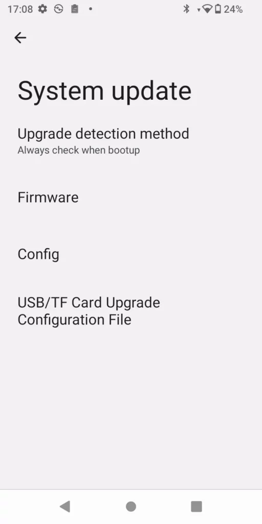
Configure via Web GUI
Open a web browser on a PC and enter the IP address for the WP856. Then log in with the administrator username and password. Go to Maintenance → Upgrade → Firmware. In the Upgrade web page, enter the IP address or the FQDN for the upgrade server and choose to upgrade via TFTP, HTTP, or HTTPS (The default setting is HTTPS). Save and apply the changes, press the Upgrade button, or reboot the phone to initiate the firmware upgrade process.
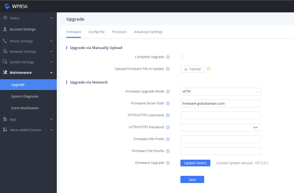
Upload Firmware Locally
If there is no HTTP(S)/TFTP server, users could also upload the firmware to the WP856 directly via Web GUI. Please follow the steps below to upload firmware to WP856 locally.
- Download the latest WP856 firmware file from the following link and save it on your PC.
https://www.grandstream.com/support/firmware - Log in to the Web GUI as an administrator on the PC.
- Go to Web GUI → Maintenance → Upgrade → Firmware.
- Click the “Upload” button, and a window will prompt you to select the firmware file to upload.
- Select the firmware file from your PC. Then uploading progress will show at the button where it was “Upload” in the above step.
- When uploading is done, users can see the upgrading process start on the WP856 LCD.
- The phone will reboot again with the new firmware version upgraded.

No Local Firmware Servers
Service providers should maintain their firmware upgrade servers. For users who do not have a TFTP/HTTP/HTTPS server, some free Windows version TFTP servers are available for download from:
https://www.solarwinds.com/free-tools/free-tftp-server and http://www.tftpd64.com/.
Please check our website at https://www.grandstream.com/support/firmware for the latest firmware.
Instructions for local firmware upgrade via TFTP:
- Unzip the firmware files and put all of them in the root directory of the TFTP server.
- Connect the PC running the TFTP server and the WP856 device to the same LAN segment;
- Launch the TFTP server and go to the File menu → Configure → Security to change the TFTP server’s default setting from “Receive Only” to “Transmit Only” for the firmware upgrade;
- Start the TFTP server and configure the TFTP server in the phone’s web configuration interface.
- Configure the Firmware Server Path on your WP856 to the IP address of the PC;
- Update the changes and reboot the WP856.
End users can also choose to download a free HTTP server from http://httpd.apache.org/ or use a Microsoft IIS web server.
Provisioning and Configuration File Download
WP856 SIP Device can be configured via the Web Interface as well as via a Configuration File through HTTP/HTTPS. The “Config Server Path” is the HTTP or HTTPS server path for the configuration file. It needs to be set to a valid URL, either in FQDN or IP address format. The “Config Server Path” can be the same or different from the “Firmware Server Path”.
A configuration parameter is associated with each particular field in the web configuration page. A parameter consists of a Capital letter P and 1 to 5 (could be extended to more in the future) digit numbers. i.e., P2 is associated with the “Admin Password” in the Web GUI → System Settings → Security Settings🡪User Info Management page. For a detailed parameter list, please refer to the corresponding firmware release configuration template in the following link:
https://www.grandstream.com/support/tools
When the WP856 boots up, it will issue an HTTP(S) request to download a configuration XML file named “cfgxxxxxxxxxxxx.xml”, where “xxxxxxxxxxxx” is the MAC address of the phone, i.e., “cfgec74d700aabb.xml”. If downloading the “cfgxxxxxxxxxxxx.xml” file is not successful, the provision program will download a generic cfg<MODEL>.xml file; if this one fails as well, then it downloads cfg.xml.
The configuration file name should be in lowercase letters.
For more details on XML provisioning, please refer to the following document: https://documentation.grandstream.com/knowledge-base/sip-device-provisioning-guide/
FACTORY RESET
Restore to Factory Default via Touchscreen
There are two methods to restore the WP856 to the factory default settings.
- On the WP856 idle screen, go to GsSettings → Advanced Settings → Factory reset.
- In the new window, confirm the reset using the left softkey.
3. Once confirming the factory reset, WP856 will reboot with the default factory settings.
Restore to Factory Default via the LCD Settings
- Go to GsSettings → Advanced Settings → Factory Reset
- Select the factory reset option, the device will be rebooted, and after this, all the WP856 data will be erased
Restore to Factory Default via the Web GUI
- Log in to WP856 Web GUI and go to Maintenance → Upgrade → Advanced Settings.
- At the bottom of the page, click on the Reset button for a Factory reset.

3. A dialog box will pop up to confirm the factory reset.
4. Click OK to restore the phone to factory settings.
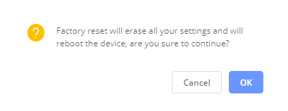
SDK INTERFACE
The WP856 operating system is developed based on the Android TM platform. In addition to inheriting the functional interface of Android, it also provides an interface for third-party application development according to user needs.
For details about the SDK, please refer to the document “Android Framework Service Guide“
CHANGE LOG
This section documents significant changes from previous firmware versions. Only major new features or major document updates are listed here. Minor updates for corrections or editing are not documented here.
Firmware Version 1.0.3.16_GS_207.0.3.16
- No major changes.
Firmware Version 1.0.3.16_GS_205.0.3.16
- Added Guest Features [Guest Features]
- Added Wi-Fi Monitoring tool [Capture in Monitor Mode]
- Added Headset Noise Shield feature [Headset Noise Shield]
- Added Handset Noise Shield feature [Handset Noise Shield]
- Added Noise Suppression feature [Noise Suppression Mode]
- Added Account Sharing feature [Account Sharing]
- Added Account Disaster Recovery feature [Account Disaster Recovery]
- Added Programmable Keys feature [Programmable Keys]
- Updated minimum TLS version to 1.2 or above. [Check Domain Certificates]
- Added Monitor settings. [Monitor]
Firmware Version 1.0.1.11
- This is the initial release.