
WELCOME
WP810/WP822/WP825 are Cordless Wi-Fi IP Phones featuring dual-band 802.11a/b/g/n/ac Wi-Fi and supports Wi-Fi roaming. The combination of advanced telephony features and durability make them ideal for mobilizing your VoIP network in residences, warehouses, retail stores, hotels and many more environments. Due to a ruggedized design, these phones are safe for accidental drops and they are as well waterproof and dustproof, with large rechargeable batteries for long period of use, making them an ideal addition for homes and businesses alike.
PRODUCT OVERVIEW
Feature Highlights
The following table contain the major features of the WP810, WP822 and WP825:
 WP810 |
|
 WP822 |
|
 WP825 |
|
Table 1: WP810/WP822/WP825 Features at a Glance
Technical Specifications
The following table resumes all the technical specifications including the protocols/standards supported, voice codecs, telephony features, languages and upgrade/provisioning settings.
- WP810
Protocols/Standards | SIP RFC3261, TCP/IP/UDP, RTP/RTCP, HTTP/HTTPS, ARP, ICMP, DNS (A record, SRV, NAPTR), DHCP, SSH, TFTP, NTP, STUN, SIMPLE, 802.1x, TLS, SRTP, IPv6 |
Voice Codecs and Capabilities | Support for G.711μ/a, G.729A/B, G.722 (wide-band), iLBC, Opus, in-band and out-of-band DTMF (In audio, RFC2833, SIP INFO), VAD, CNG, AEC, PLC, AJB, AGC, ANS |
Graphic Display | 1.8-inch (128×160) TFT color LCD |
Peripherals | 2 soft keys, dial, hangup, speakerphone, phonebook, backlit keypad, proximity senor, vibration motor, volume button and navigation keys |
Push-to-Talk | Customizable button for push-to-talk. |
Auxiliary Ports | 3.5 mm headset jack, Micro-USB port for charging, dual-MIC, dual-color MWI LED. |
Telephony Features | Hold, transfer, forward, 3-way audio conference, downloadable phonebook XML (up to 500 items), call waiting, call log (up to 100 records), off-hook auto dial, auto answer, flexible dial plan, personalized music ringtones, server redundancy and fail-over, push to talk |
Security | User and administrator level passwords, MD5 and MD5-sess based authentication, 256-bit AES based secure configuration file, SRTP, TLS, 802.1x media access control |
HD Audio | Yes, both on handset and speakerphone with support for wideband audio, HAC supported |
QoS | 802.11e and Layer 3 (ToS, DiffServ, MPLS) QoS |
Multi-language | English, Chinese, German, French, Italian, Portuguese, Russian, Spanish, Turkish, Japanese, Hewbrew and more |
Upgrade/ Provisioning | Firmware upgrade via TFTP/HTTP/HTTPS/FTP/FTPS, mass provisioning using encrypted XML configuration file, manual upload. |
Power & Green Energy Efficiency | Universal power adapter included Input: 100-240VAC; Output: +5VDC, 1A (5W) 1500mA Li-ion battery, 120h standby time and 6h talk time |
Physical | Handset Dimensions : 158.5 x 50 x 22.5mm Charger cradle dimensions : 81.15 x 75.89 x 36.36mm Handset weight: 120g Handset package weight (not including QIG): 340g |
Temperature and Humidity | Operating Temperature: 0~45°C; Operating Humidity: 10~90%(non-condensing) Storage Temperature: -20~60°C; Storage Humidity:10~90%(non-condensing |
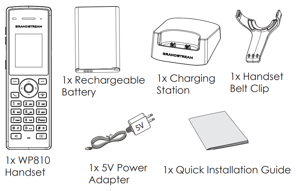
Package Contents | Handset unit, universal power supply, charger cradle, belt clip, 1 Li-ion battery. Quick Installation Guide. |
Compliance | FCC, CE, RCM, IC |
Table 2: WP810 Technical Specifications
- WP822
Protocols/Standards | SIP RFC3261, TCP/IP/UDP, RTP/RTCP, HTTP/HTTPS, ARP, ICMP, DNS (A record, SRV, NAPTR), DHCP, SSH, TFTP, NTP, STUN, SIMPLE, 802.1x, TLS, SRTP, IPv6 |
Voice Codecs and Capabilities | Support for G.711μ/a, G.729A/B, G.722 (wide-band), iLBC, Opus, in-band and out-of-band DTMF (In audio, RFC2833, SIP INFO), VAD, CNG, AEC, PLC, AJB, AGC, ANS |
Graphic Display | 2.4 inch (240x320) TFT color LCD |
Peripherals | 3 soft keys, dial, hang-up, speakerphone, phonebook, backlit keypad, proximity sensor, vibration motor, volume button, navigation keys, and accelerometer supporting configurable gestures |
Push-to-Talk | Customizable button for push-to-talk. |
Auxiliary Ports | 3.5 mm headset jack, Micro-USB port for charging, dual-MIC, dual-color MWI LED. |
Telephony Features | Hold, transfer, forward, 3-way audio conference, call waiting, call log (up to 100 records), downloadable phonebook (XML, up to 500 items) off-hook auto dial, auto answer, flexible dial plan, personalized music ringtones, server redundancy and fail-over, push to talk, LDAP |
Security | User and administrator level passwords, MD5 and MD5-sess based authentication, 256-bit AES based secure configuration file, SRTP, TLS, 802.1x media access control |
HD Audio | Yes, both on handset and speakerphone with support for wideband audio, HAC supported |
QoS | 802.11e (WMM) and Layer 3 (ToS, DiffServ, MPLS) QoS |
Multi-language | English, Chinese, German, French, Italian, Portuguese, Russian, Spanish, Japanese, Hewbrew and more |
Upgrade/ Provisioning | Firmware upgrade via TFTP/HTTP/HTTPS/FTP/FTPS, mass provisioning using encrypted XML configuration file, manual upload. |
Power & Green Energy Efficiency | Universal power adapter included |
Physical | Handset dimensions: 164.0 x 52.0 x 25.8mm |
Temperature and Humidity | Operating Temperature: 0ºC to 45ºC; Operating Humidity: 10-90% (non-condensing) |
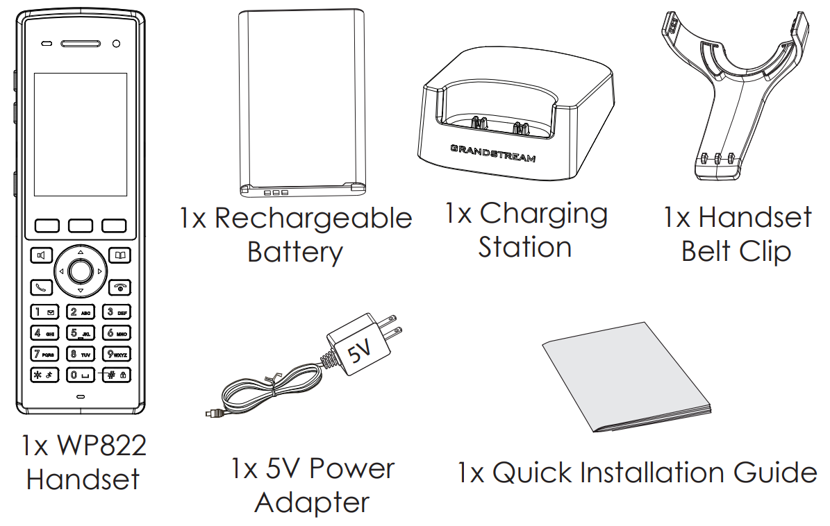
Package Contents | Handset unit, universal power supply, charger cradle, belt clip, 1 Li-ion battery, Quick Start Guide |
Compliance | FCC, CE, RCM, IC, UKCA |
Table 3: WP822 Technical Specifications
- WP825
Protocols/Standards | SIP RFC3261, TCP/IP/UDP, RTP/RTCP, HTTP/HTTPS, ARP, ICMP, DNS (A record, SRV, NAPTR), DHCP, SSH, TFTP, NTP, STUN, SIMPLE, 802.1x, TLS, SRTP, IPv6 |
Voice Codecs and Capabilities | Support for G.711μ/a, G.729A/B, G.722 (wide-band), iLBC, Opus, in-band and out-of-band DTMF (In audio, RFC2833, SIP INFO), VAD, CNG, AEC, PLC, AJB, AGC, ANS |
Graphic Display | 2.4 inch (240x320) TFT color LCD |
Peripherals | 3 soft keys, dial, hang-up, speakerphone, phonebook, backlit keypad, proximity sensor, vibration motor, volume button, navigation keys, and accelerometer supporting configurable gestures |
Push-to-Talk | Customizable button for push-to-talk. |
Auxiliary Ports | 3.5 mm headset jack, Micro-USB port for charging, dual-MIC, dual-color MWI LED. |
Telephony Features | Hold, transfer, forward, 3-way audio conference, call waiting, call log (up to 100 records), downloadable phonebook (XML, up to 500 items) off-hook auto dial, auto answer, flexible dial plan, personalized music ringtones, server redundancy and fail-over, push to talk, LDAP |
Security | User and administrator level passwords, MD5 and MD5-sess based authentication, 256-bit AES based secure configuration file, SRTP, TLS, 802.1x media access control |
HD Audio | Yes, both on handset and speakerphone with support for wideband audio, HAC supported |
QoS | 802.11e (WMM) and Layer 3 (ToS, DiffServ, MPLS) QoS |
Multi-language | English, Chinese, German, French, Italian, Portuguese, Russian, Spanish, Hewbrew, Japanese and more |
Upgrade/ Provisioning | Firmware upgrade via TFTP/HTTP/HTTPS/FTP/FTPS, mass provisioning using encrypted XML configuration file, manual upload. |
Power & Green Energy Efficiency | Universal power adapter included |
Physical | Handset dimensions: 164.0 x 52.0 x 25.8mm |
Weatherproof | IP67 Rated -Water-proof, dust-proof, cleaning chemical resistant, anti-microbial casing and 2.5m drop safe |
Temperature and Humidity | Operating Temperature: 0ºC to 45ºC; Operating Humidity: 10-90% (non-condensing) |
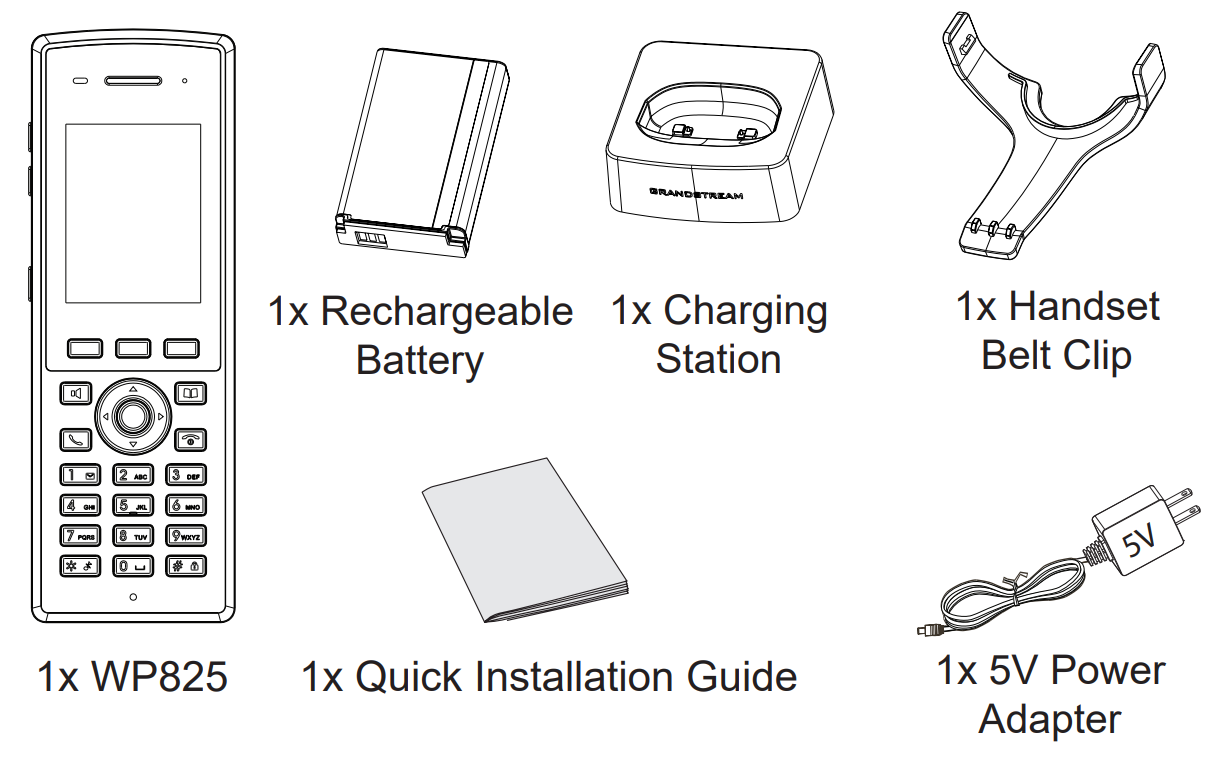
Package Contents | Handset unit, universal power supply, charger cradle, belt clip, 1 Li-ion battery, Quick Start Guide |
Compliance | FCC, CE, RCM, IC, UKCA |
Table 4: WP825 Technical Specifications
GETTING STARTED
This chapter provides basic installation instructions including the list of the packaging contents and also information for obtaining best performance with the WP810, WP822 and WP825.
Equipment Packaging
WP810/WP822/WP825 |
|
Table 5: Equipment Packaging
- WP822
- WP825
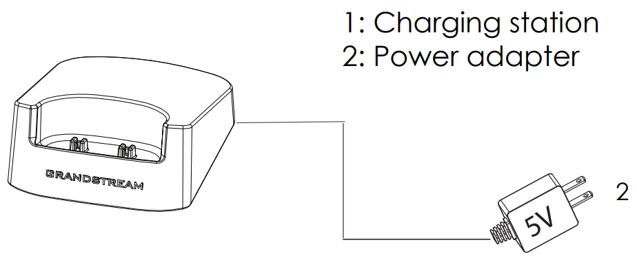
Setting up the Phone
Charging Station
Plug the power adapter into a power source socket to start using the charging station.
Handset
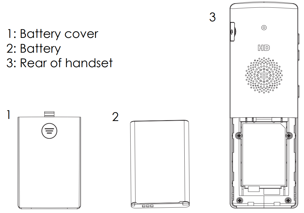
Please refer to the following steps in order to setup your WP810/WP822/WP825 phone:
- Open the battery cover.
- Insert the battery with the electrodes in the bottom left corner.
- Close the battery cover.
Battery Information
WP810
- Technology: Rechargeable Li-ion Battery
- Voltage: 3.8V (Nominal Voltage 3.8V / Limited charge Voltage: 4.35V)
- Capacity: 1500mAh
- Standby time: up to 120 hours
- Talk time: up to 6 hours’ active talk time
WP822
- Technology: Rechargeable Li-ion Battery
- Voltage: 3.8V (Nominal Voltage 3.8V / Limited charge Voltage: 4.35V)
- Capacity: 2000mAh
- Standby time: up to 200 hours
- Talk time: up to 8 hours’ active talk time
WP825
- Technology: Rechargeable Li-ion Battery
- Voltage: 3.8V (Nominal Voltage 3.8V / Limited charge Voltage: 4.35V)
- Capacity: 2000mAh
- Standby time: up to 200 hours
- Talk time: up to 8 hours’ active talk time
In order to get the best performance of your WP810/WP822/WP825, we recommend using original battery provided in the package. The specifications may differ depending on the age and capacity of the battery used.
Handset Keys Description
The WP810/WP822/WP825 Wireless IP phone enhances communication and combines usability and scalability in industries such as warehousing, catering and retail as well as in factory settings. The following screenshot describe the the handsets LCD screen and the main hardware components.
- WP810
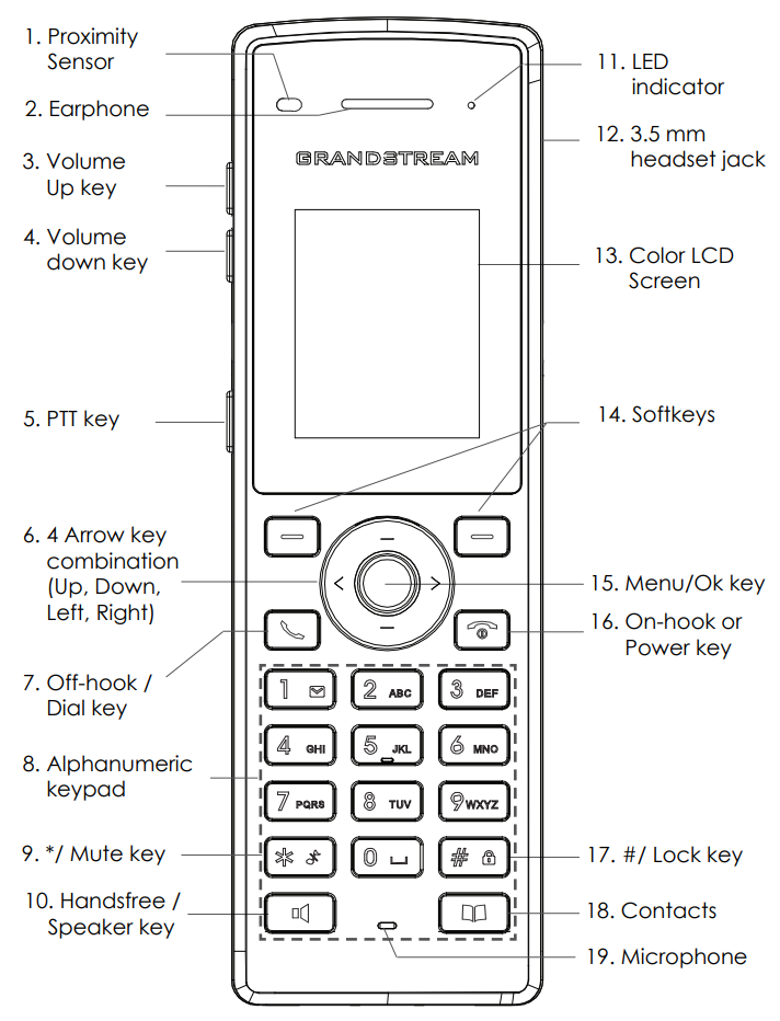
The following table describe the WP810 keypad keys.
Key | Description | |
1. | Proximity sensor | The proximity senor can detect and measure gravitational acceleration, tilt, vibration, altitude changes, and static position. |
2. | Earphone | Delivers audio output. |
3,4 | Volume up / Down Keys | Configure the handset and ringtone volume. |
5. | PTT Key | PTT (Push-to-Talk) button, to initiate PTT call. |
6. | * / Mute key | Keep pressing on * in idle screen to mute/unmute the ringtone. |
7. | Arrow key combination (Up, Down, Left, Right) | Allows navigation of the cursor through the displayed menu options. |
8. | Off-hook / Dial key | Enters dialing mode, or dials number entered. |
9. | Alphanumeric Keypad | Provides the digits, letters, and special characters in context-sensitive applications. For + sign, press and hold key 0. |
10. | Hands-free / Speaker key | Activates or deactivates the mute feature when keep pressing on * in idle screen. |
11. | LED indicator | 1dual-color LED indicator indicating power, call, battery, message waiting… |
12. | 3.5 mm headset jack | Phone connector for the headphones/headsets. |
13. | Color LCD Screen | 1.8-inch (128×160) color LCD |
14. | Softkeys | Correspond to functions displayed on the LCD. These functions change depending on the current context. |
15. | Menu/OK key | Access to contacts list. |
16. | On-hook or Power key | Selects the option chosen by the cursor or enters the main menu from the home screen. |
17. | # / Lock key | Terminates calls or turns the handset on / off. |
18. | Contacts | Locks keypad against unintentional entries when keep pressing #.
|
19. | Microphone | Picks up audio earpiece and hands-free calls. |
- WP822
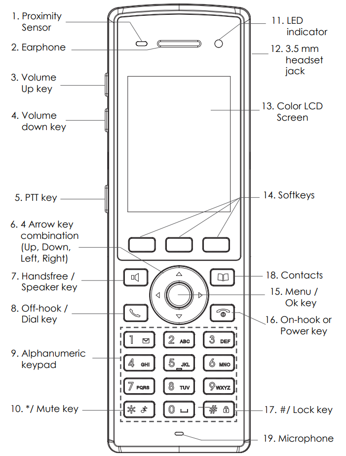
The following table describe the WP822 keypad keys.
Key | Description | |
1. | Proximity sensor | The proximity senor can detect and measure gravitational acceleration, tilt, vibration, altitude changes, and static position. |
2. | Earphone | Delivers audio output. |
3,4 | Volume up / Down Keys | Configure the handset and ringtone volume. |
5. | PTT Key | PTT (Push-to-Talk) button, to initiate PTT call. |
6. | * / Mute key | Keep pressing on * in idle screen to mute/unmute the ringtone. |
7. | Arrow key combination (Up, Down, Left, Right) | Allows navigation of the cursor through the displayed menu options. |
8. | Off-hook / Dial key | Enters dialing mode, or dials number entered. |
9. | Alphanumeric Keypad | Provides the digits, letters, and special characters in context-sensitive applications. For + sign, press and hold key 0. |
10. | Hands-free / Speaker key | Activates or deactivates the mute feature when keep pressing on * in idle screen. |
11. | LED indicator | 1dual-color LED indicator indicating power, call, battery, message waiting… |
12. | 3.5 mm headset jack | Phone connector for the headphones/headsets. |
13. | Color LCD Screen | 1.8-inch (128×160) color LCD |
14. | Softkeys | Correspond to functions displayed on the LCD. These functions change depending on the current context. |
15. | Menu/OK key | Access to contacts list. |
16. | On-hook or Power key | Selects the option chosen by the cursor or enters the main menu from the home screen. |
17. | # / Lock key | Terminates calls or turns the handset on / off. |
18. | Contacts | Locks keypad against unintentional entries when keep pressing #.
|
19. | Microphone | Picks up audio earpiece and hands-free calls. |
- WP825
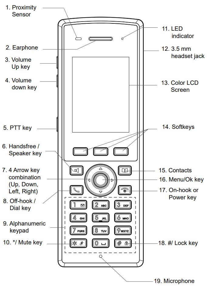
The following table describe the WP825 keypad keys.
Key | Description | |
1. | Proximity sensor | The proximity senor can detect and measure gravitational acceleration, tilt, vibration, altitude changes, and static position. |
2. | Earphone | Delivers audio output. |
3,4 | Volume up / Down Keys | Configure the handset and ringtone volume. |
5. | PTT Key | PTT (Push-to-Talk) button, to initiate PTT call. |
6. | * / Mute key | Keep pressing on * in idle screen to mute/unmute the ringtone. |
7. | Arrow key combination (Up, Down, Left, Right) | Allows navigation of the cursor through the displayed menu options. |
8. | Off-hook / Dial key | Enters dialing mode, or dials number entered. |
9. | Alphanumeric Keypad | Provides the digits, letters, and special characters in context-sensitive applications. For + sign, press and hold key 0. |
10. | Hands-free / Speaker key | Activates or deactivates the mute feature when keep pressing on * in idle screen. |
11. | LED indicator | 1dual-color LED indicator indicating power, call, battery, message waiting… |
12. | 3.5 mm headset jack | Phone connector for the headphones/headsets. |
13. | Color LCD Screen | 1.8-inch (128×160) color LCD |
14. | Softkeys | Correspond to functions displayed on the LCD. These functions change depending on the current context. |
15. | Menu/OK key | Access to contacts list. |
16. | On-hook or Power key | Selects the option chosen by the cursor or enters the main menu from the home screen. |
17. | # / Lock key | Terminates calls or turns the handset on / off. |
18. | Contacts | Locks keypad against unintentional entries when keep pressing #.
|
19. | Microphone | Picks up audio earpiece and hands-free calls. |
Icons Description
Following table contains description of each icon that might be displayed on the screen of the WP810/WP822/WP825.
Battery status Charging | |
Wi-Fi not enabled/configured | |
Wi-Fi signal status | |
Outgoing Call notification | |
Missed Call notification | |
Rejected Call notification | |
Incoming Call notification | |
Mute enabled icon | |
DND enabled icon | |
SRTP & TLS enabled icon | |
 | Contacts |
 | SMS |
 | Call History |
 | Voice Mail |
 | Diagnosis |
 | Settings |
 | Status |
Handset Menu
The handset has an easy-to-use menu structure. Every menu opens a list of options. To open the main menu, unlock first the handset and press “Menu” (softkey in the middle). Press Arrow keys to navigate to the menu option you require. Then press “Select” (left softkey) or OK/Selection key to access further options or confirm the setting displayed. To go to the previous menu item, press “Back” (right softkey). You can press Power key at any time to cancel and return to standby mode.
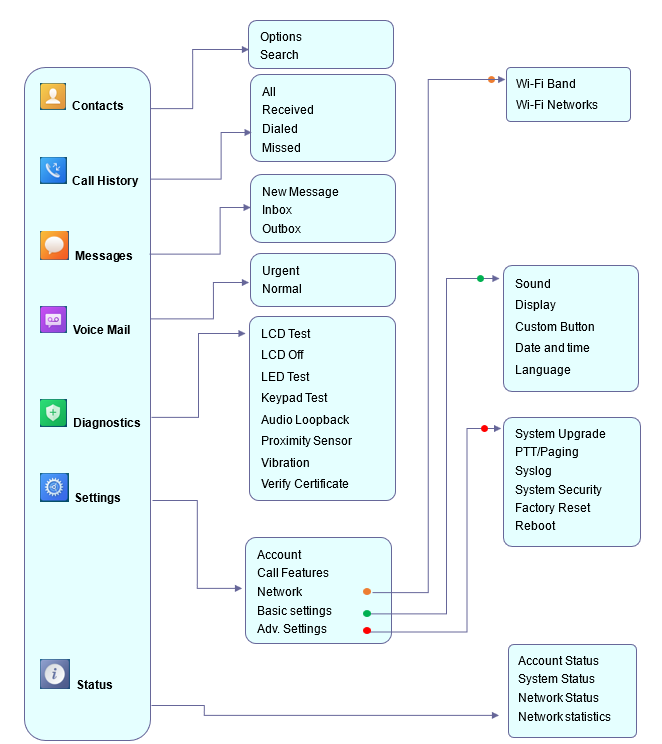
Contacts | Display the list of the registered contacts and also the groups contacts with the ability of searching, adding or editing the entries and also deleting the selected contacts. |
Call History | Display the call history: Missed Calls, Accepted Calls, Outgoing Calls or All Calls. You can add contacts to Shared Contacts directly from call logs. |
SMS | SMS stands for Short Message Service and referred to as a “text message”. With a SMS, you can send a message by pressing “New Message” of up to 160 characters to another device or check the received ones. |
Voice Mail | Select: Play voice mail messages received.
|
Diagnostics |
|
Settings |
|
Status | Displays account status, system info, Network status and network statistics
|
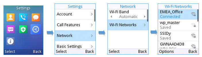
Connecting the handset to Wi-Fi Network
The WP810/WP822/WP825 phone supports dual-band 802.11a/b/g/n/ac Wi-Fi, please refer to the following steps in order to connect your handset to the Wi-Fi networks:
- On LCD menu, press Menu key and navigate to Settings → Network.
- Select “Wi-Fi Band” (automatic, 2.4GHz or 5GHz) and navigate to “Wi-Fi Networks”. A list of Wi-Fi networks will be displayed.
- Select the desired network to connect to. (Enter the correct password to connect if requested)
The handset will display Wi-Fi icon on the main LCD menu if the connection to the Wi-Fi network is successful.
Obtain IP Address
In order to know which IP address is assigned to your handset, please follow below steps:
- Unlock first your phone and press “Menu” (Middle softkey) or Ok button to view operation menu.
- Press Arrow (Up, Down, Left, Right) keys to move the cursor to Status icon
 , then press “Select” (left softkey) or Ok button.
 - Access Network Status menu to obtain the IP address of the WP810/WP822/WP825.
 , then press “Select” (left softkey) or Ok button.
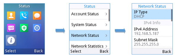
WEB GUI ACCESS CONFIGURATION
The WP810/WP822/WP825 can be configured using:
- Web GUI embedded on the handset using PC’s web browser.
- LCD Configuration Menu using the WP810/WP822/WP825 keypad.
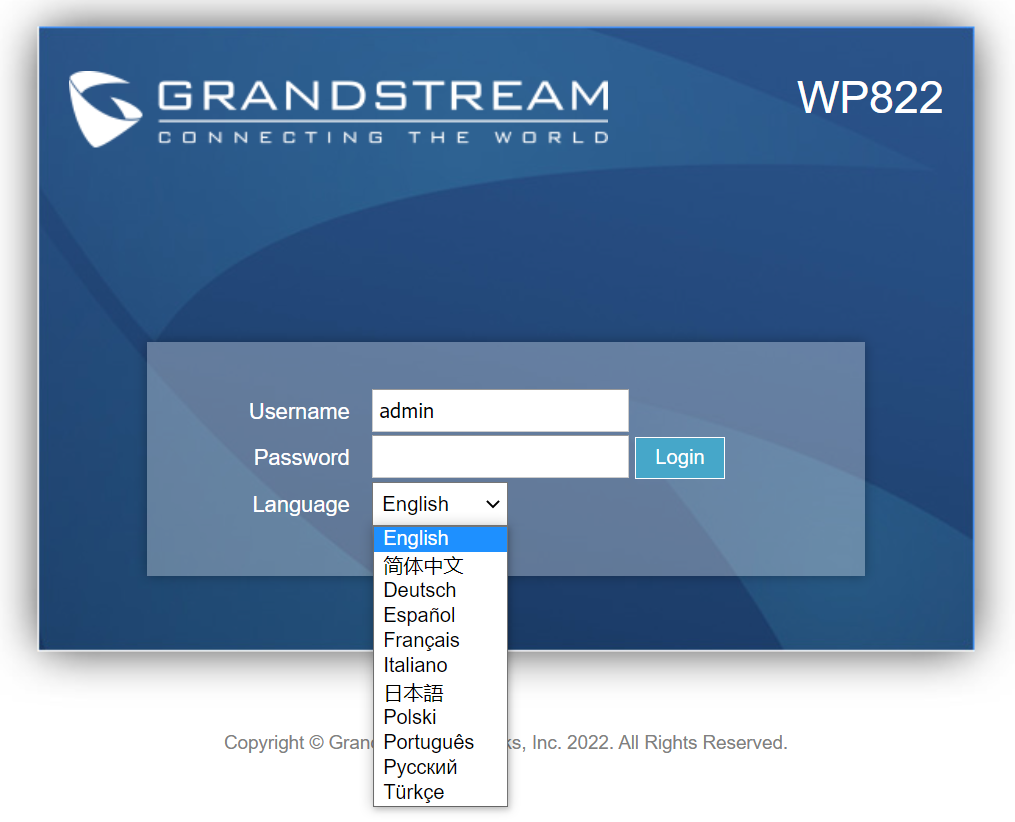
Configuration via Web Browser
The WP810/WP822/WP825 embedded Web server responds to HTTP/HTTPS GET/POST requests. Embedded HTML pages allow a user to configure the handset through a Web browser such as Google Chrome, Mozilla Firefox.
Accessing the Web UI
- Connect the computer to the same network as WP810/WP822/WP825.
- Make sure the handset is booted up and powered correctly.
- You may check the IP address on the phone LCD menu Status 🡪 Network Status. Please see Obtain WP810/WP822/WP825 IP Address
- Open Web browser on your computer and enter the WP810/WP822/WP825 IP address in the address bar of the browser.
- Enter the administrator’s username and password to access the Web Configuration Menu.
Web GUI Languages
Users can select the language in web GUI login page, or at the upper right of the web GUI after logging in.
Saving the Configuration Changes
When changing any settings, always submit them by pressing Save and Apply buttons. If using the Save button, after making all the changes, click on the Apply button on top of the page to submit.
Web UI Access Level Management
There are two default passwords for the login page:
User Level | User Name | Password | Web Pages Allowed |
End User Level | user | Defined by admin | Only Status, Phone Settings, System Settings, Maintenance and System Application with limited options. |
Administrator Level | admin | Random password generated after entering a numbers combination on the keypad | All pages |
Table 11: Web UI Access Level
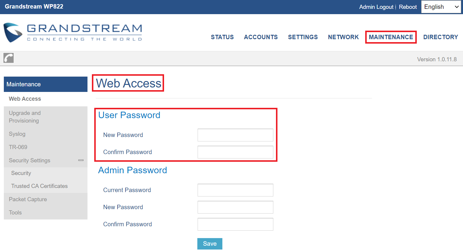
Changing User Level Password
- Access the Web GUI of your phone using the admin’s username and password.
- Press Login to access your settings.
- Go to Maintenance 🡪 Web Access.
- locate User Password section:
- Type in your new user password in New Password field.
- Type in again same entered password in Confirm Password field.
- Press Save button to save your new settings.
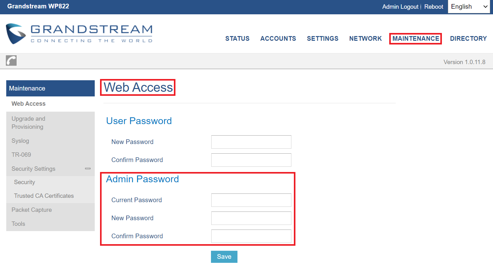
Changing Admin Level Password
- Access the Web GUI of your WP810/WP822/WP825 using the admin’s username and password. (Default username and password is admin/Random Password from the sticker on the back of the unit).
- Press Login to access your settings.
- Go to Maintenance 🡪 Web Access.
- locate Admin Password section:
- Type in the admin password in the Current Password field
- Type in your new admin password in New Password field.
- Type in again same entered password in Confirm Password field.
- Press Save button to save your new settings.
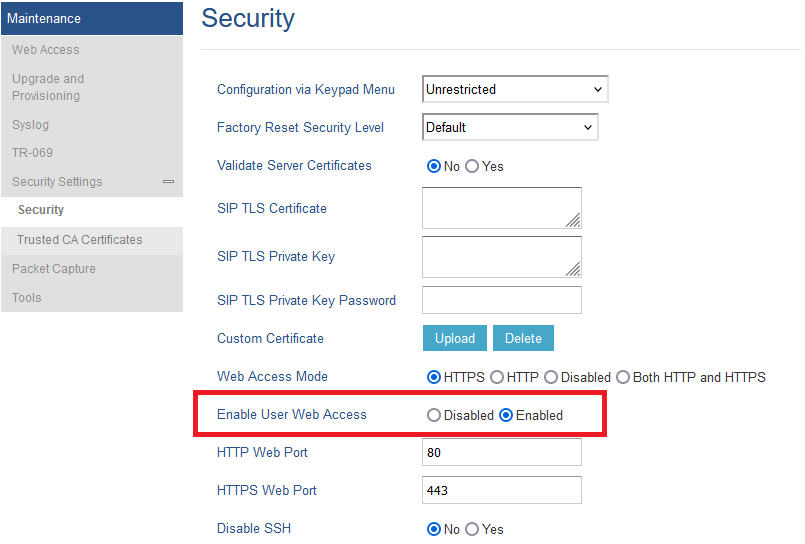
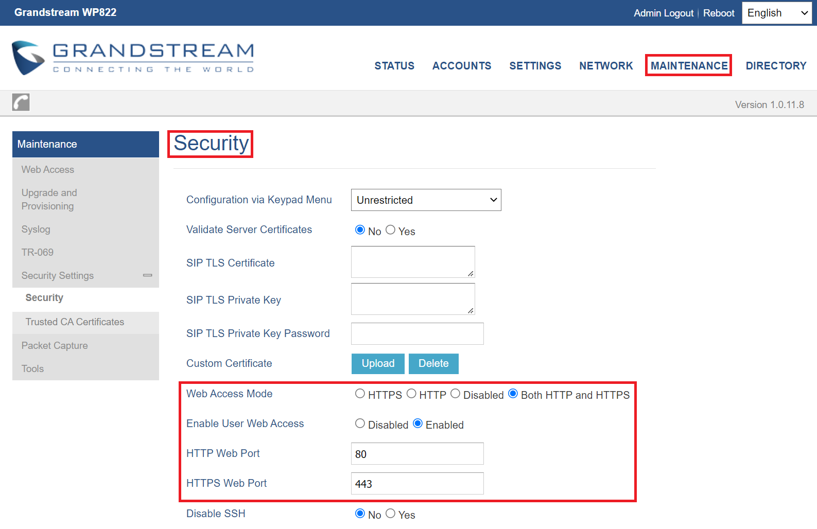
Changing HTTP/HTTPS Web Access Port
- Access the Web GUI of your handset using the admin’s username and password. (Default username and password are admin/Random password from the sticker on the back of the unit.).
- Press Login to access your settings.
- Go to Maintenance 🡪 Security Settings 🡪 Security
- In Web Access Mode, select the access method depending on desired protocol (HTTP or HTTPS or Both)
- Locate HTTP / HTTPS Web Port field and change it to your desired/new HTTP / HTTPS port.
Note: By default, the HTTP port is 80 and HTTPS is 443. - Press Save button to save your new settings.
WEB GUI SETTINGS
This section describes the options in the WP810/WP822/WP825 Web UI. As mentioned, you can log in as an administrator or an end user.
- Status: Display account status, network status and system info.
- Accounts: Configure accounts with general settings, SIP settings, codec settings, call settings and advanced settings.
- Settings: Configure general settings, call settings, ringtone, Video Settings, Multicast paging
- Network: Wi-Fi settings, and advanced network settings.
- Maintenance: Configure upgrade and provisioning settings and system diagnosis.
- Directory: Configure phonebook settings and Call History
Status Page Definitions
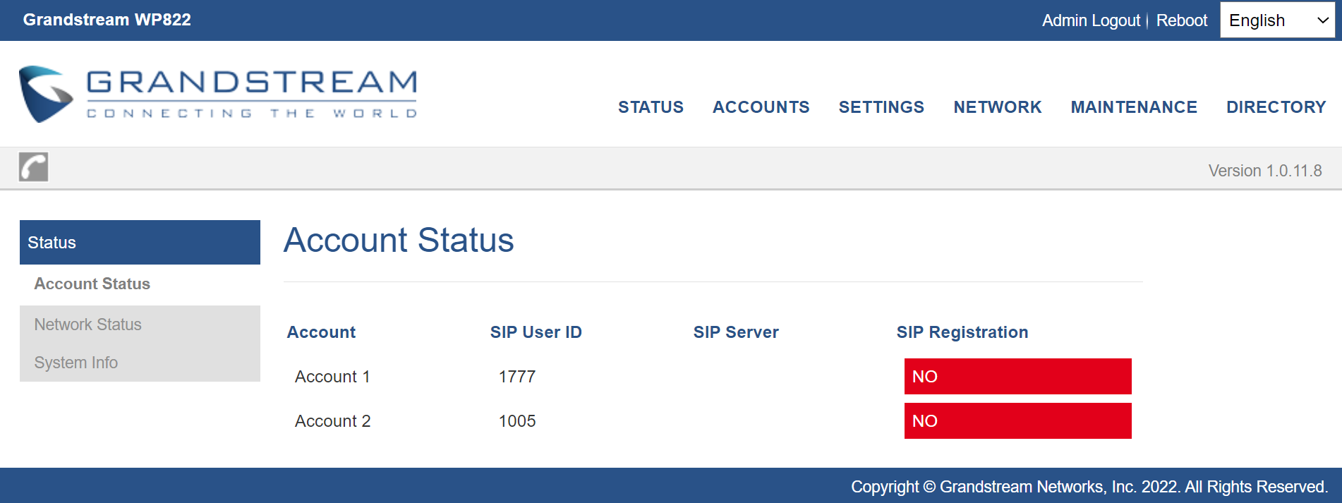
Status/Account Status
Account | Displays list of configured accounts. |
SIP user ID | Displays the numbers of the configured accounts. |
SIP Server | Displays list of SIP Server user by the configured accounts. |
SIP Registration | Shows the status of SIP registration. If the SIP account is successfully registered, it will display “Registered” with green background. If the SIP account is not registered, it will display “Unregistered” with grey background. |
Table 12: Status/Account Status
Status/Network Status
MAC Address | Shows Device ID in hexadecimal format. This is needed by network administrators for troubleshooting. The MAC address will be used for provisioning and can be found on the label on original box and on the label located on the bottom panel of the device. |
IPv4 Address Mode | Indicates the configured address mode: DHCP or Static IP |
IPv4 Address | Displays assigned IP address. Example: 192.168.5.110 |
Subnet Mask | Displays assigned subnet mask. Example: 255.255.255.0 |
Gateway | Displays assigned default gateway. Example: 192.168.5.1 |
IPv6 Address Mode | Indicates the configured address mode: DHCP or Static IP |
IPv6 Address | Displays assigned IP address. |
DNS | Shows assigned DNS server address. |
NAT Type | Indicates type of NAT for each Profile. (Based on STUN protocol.) |
NAT Traversal | |
Account 1 | Indicates type of NAT for Account 1. |
Account 2 | Indicates type of NAT for Account 2. |
Status/System Info
Product Model | Product model of the phone. |
Part Number | Product part number. |
Software Version | |
Boot | Booting code version. |
Manifest | Specifies Manifest version. |
Core | Specifies Core version. |
Base | Specifies Base version. |
IP Geographic Information | |
Time Zone | Time Zone information |
System Time | |
System Up Time | System up time since last reboot. |
System Time | Shows actual time and date according to your configuration |
Service Status | |
Gui | Reveals status of GUI |
Phone cpe | Reveals status of phone Reveals status of Customer Premise Equipment |
System Information | |
Download System Information | Click to “download” the user’s configuration file. |
User Space | |
User Space Used | Reveals status of user space |
Database Status | Reveals status of database |
Core Dump | |
Generate core dump | Generate core dump by killing program. |
Core Dump Clear Core Dumps | Core Dump status Click on “Start” to clear all the core dumps |
Accounts Page Definitions
Account/General Settings
Account Active | This field indicates whether the account is active. |
Account Name | Configure the name associated with each account to be displayed on the LCD. |
SIP Server | Configures the URL or IP address, and port of the SIP server. This is provided by your VoIP service provider (ITSP). |
Secondary SIP Server | Configures the URL or IP address, and port of the SIP server. This will be used when the primary SIP server fails. |
Outbound Proxy | Configures the IP address or Domain name of the Primary Outbound Proxy, Media Gateway, or Session Border Controller. It is used by the phone for Firewall or NAT penetration in different network environments. If a symmetric NAT is detected, STUN will not work and ONLY an Outbound Proxy can provide a solution. |
Backup Outbound Proxy | IP address or Domain name of the Secondary Outbound Proxy which will be used when the primary proxy cannot be connected. |
SIP User ID | Configures the SIP service subscriber’s ID used for authentication. It can be identical to or different from the SIP User ID. |
Authenticate ID | Configures the account password required for the phone to authenticate with the ITSP (SIP) server before the account can be registered. After it is saved, this will appear as hidden for security purpose. |
Authenticate Password | The account password required for the phone to authenticate with the SIP server before the account can be registered. |
Name | Configures the SIP server subscriber’s name (optional) that will be used for Caller ID display. |
Voice Mail Access Number | Defines the voice mail portal access number to allow users accessing their voice messages. |
Account Display | When set to “Username”, LCD will display Username if it is not empty; When set to “User ID”, LCD will display User ID if it is not empty. |
Table 15: Account/General Settings
Account/Network Settings
DNS Mode | This parameter controls how the Search Appliance looks up IP addresses for hostnames. There are four modes: A Record, SRV, NATPTR/SRV, Use Configured IP. The default setting is “A Record”. If the user wishes to locate the server by DNS SRV, the user may select “SRV” or “NATPTR/SRV”. If “Use Configured IP” is selected, please fill in the three fields below:
If SIP server is configured as domain name, phone will not send DNS query, but use “Primary IP” or “Backup IP x” to send SIP message if at least one of them are not empty. Phone will try to use “Primary IP” first. After 3 tries without any response, it will switch to “Backup IP x”, and then it will switch back to “Primary IP” after 3 re-tries. If SIP server is already an IP address, phone will use it directly even “User Configured IP” is selected |
Maximum Number of SIP Request Retries | Specifies the maximum number of retries on SIP Requests. |
DNS SRV Fail-over Mode | The option will decide which IP is going to be used in sending SIP packets after IPs for SIP server host are resolved with DNS SRV.
|
Failback Timer | Specifies the time interval (in minutes) that the device should continue to send SIP requests (REGISTER or INVITE) to the failover IP. Once it expires, the SIP requests will be sent to the preferred IP. The default value is 60 minutes, and the max value is 45 days. |
Register Before DNS SRV Failover | This option allows to choose the behavior for registering before DNS SRV Fail-over.
|
Primary IP | Configures the primary IP address where the phone sends DNS query to when “Use Configured IP” is selected for DNS mode. |
Backup IP1 | Configures the backup IP1 address where the phone sends DNS query to when “Use Configured IP” is selected for DNS mode |
Backup IP2 | Configures the backup IP2 address where the phone sends DNS query to when “Use Configured IP” is selected for DNS mode |
NAT Traversal | This parameter configures whether the NAT traversal mechanism is activated. Users could select the mechanism from No, STUN, Keep-alive, UPnP or Auto. The default setting is “No”. If set to “STUN” and STUN server is configured, the phone will route according to the STUN server. If NAT type is Full Cone, Restricted Cone or Port-Restricted Cone, the phone will try to use public IP addresses and port number in all the SIP&SDP messages. The phone will send empty SDP packet to the SIP server periodically to keep the NAT port open if it is configured to be “Keep-alive”. Configure this to be “No” if an outbound proxy is used. “STUN” cannot be used if the detected NAT is symmetric NAT. |
Proxy-Require | Adds the Proxy-Required header in the SIP message. It is used to indicate proxy-sensitive features that must be supported by the proxy. Do not configure this parameter unless this feature is supported on the SIP server. |
Table 16: Account/Network Settings
Account/SIP Settings
Basic Settings | |
TEL URI | If the phone has an assigned PSTN telephone number, this field should be set to “User=Phone”. Then a “User=Phone” parameter will be attached to the Request-Line and “TO” header in the SIP request to indicate the E.164 number.
The default setting is “Disable”. |
SIP Registration | Selects whether the phone will send SIP Register messages to the proxy/server. The default setting is “Yes”. |
Unregister On Reboot | Allows the SIP user’s registration information to be cleared when the phone reboots. The SIP REGISTER message will contain “Expires: 0” to unbind the connection. Three options are available: The default setting is “No”.
|
Register Expiration | Specifies the frequency (in minutes) in which the phone refreshes its registration with the specified registrar. The default value is 60 minutes. |
Subscribe Expiration | Specifies the frequency (in minutes) in which the phone refreshes its subscription with the specified registrar. The maximum value is The default value is 60 minutes. |
Reregister Before Expiration | Specifies the time frequency (in seconds) that the phone sends re-registration request before the Register Expiration. The default value is 0. |
Enable OPTIONS Keep Alive | Enable OPTIONS Keep Alive to check SIP Server. |
OPTIONS Keep Alive Interval | Time interval for OPTIONS Keep Alive feature in Second. |
OPTIONS Keep Alive Max Lost | Number of max lost packets for OPTIONS Keep Alive feature before the phone re-registration. |
Enable TCP Keep Alive | Enable TCP keep alive for the respective SIP account when the account protocol uses TCP/TLS. The default setting is “No”. |
Local SIP Port | Defines the local SIP port used to listen and transmit. The default value is 5060 for Account 1, 5062 for Account 2, 5064 for Account 3, 5066 for Account 4, 5068 for Account 5, 5070 for Account 6. The valid range is from 1 to 65535. |
SIP Registration Failure Retry Wait Time | Specifies the interval to retry registration if the process is failed. The valid range is 1 to 3600. The default value is 20 seconds. |
SIP T1 Timeout | SIP T1 Timeout is an estimate of the round-trip time of transactions between a client and server. If no response is received the timeout is increased and request re-transmit retries would continue until a maximum amount of time define by T2. The default setting is 0.5 seconds. |
SIP T2 Timeout | SIP T2 Timeout is the maximum retransmit time of any SIP request messages (excluding the INVITE message). The re-transmitting and doubling of T1 continues until it reaches the T2 value. Default is 4 seconds. |
SIP Timer B Timeout | Timer B is the maximum amount of time that a sender will wait for an INVITE message to be acknowledged. |
SIP Timer F Timeout | Timer F is the maximum amount of time that a sender will wait for a non INVITE message to be acknowledged. |
SIP Transport | Determines the network protocol used for the SIP transport. Users can choose from TCP, UDP and TLS. The default setting is “UDP”. |
SIP Listening Mode | Based on option “SIP Transport” and this option “SIP Listening Mode”, phone will decide which transport protocol it should listening to from the incoming request. The default setting is “Transport Only”.
|
SIP URI Scheme when using TLS | Specifies if “sip” or “sips” will be used when TLS/TCP is selected for SIP Transport. The default setting is “sips”. |
Use Actual Ephemeral Port in Contact with TCP/TLS | This option is used to control the port information in the Via header and Contact header. If set to No, these port numbers will use the permanent listening port on the phone. Otherwise, they will use the ephemeral port for the connection. The default setting is “No”. |
Outbound Proxy Mode | The Outbound proxy mode is placed in the route header when sending SIP messages, or they can be always sent to outbound proxy. |
Support SIP Instance ID | Defines whether SIP Instance ID is supported or not. Default setting is “Yes”. |
SUBSCRIBE for MWI | When set to “Yes”, a SUBSCRIBE for Message Waiting Indication will be sent periodically. The phone supports synchronized and non-synchronized MWI. The default setting is “No”. |
SUBSCRIBE for Registration | When set to “Yes”, a SUBSCRIBE for Registration will be sent out periodically. The default setting is “No”. |
Enable 100rel | The use of the PRACK (Provisional Acknowledgment) method enables reliability to SIP provisional responses (1xx series). This is very important to support PSTN internetworking. To invoke a reliable provisional response, the 100rel tag is appended to the value of the required header of the initial signaling messages. The default setting is “No”. |
Callee ID Display | When set to “Auto”, the phone will update the callee ID in the order of P-Asserted Identity Header, Remote-Party-ID Header and To Header in the 180 Ringing. If “Disabled”, callee ID will be displayed as “Unavailable”. When set to “To Header”, caller ID will not be updated and displayed as To Header. |
Caller ID Display | When set to “Auto”, the phone will look for the caller ID in the order of P-Asserted Identity Header, Remote-Party-ID Header and From Header in the incoming SIP INVITE. When set to “Disabled”, all incoming calls are displayed with “Unavailable”. When set to “From Header”, the phone will display the caller ID based on the From Header in the incoming SIP INVITE. The default setting is “Auto”. |
Add Auth Header on Initial REGISTER | To define whether authorization Header will be added on initial REGISTER from the first REGISTER. The default setting is “No”. |
Allow SIP Reset | This is used to perform a factory reset through SIP NOTIFY. When the phone receives the NOTIFY with event: RESET, the phone should perform a factory reset after the authentication. The default setting is “No”. |
Ignore Alert-Info header | This option is used to configure default ringtone. If set to “Yes”, configured default ringtone will be played. The default setting is “No”. |
Custom SIP Headers | |
Use Privacy Header | Controls whether the Privacy header will present in the SIP INVITE message or not, whether the header contains the caller info. When set to “Default”, the Privacy Header will show in INVITE only when “Huawei IMS” special feature is on. If set to “Yes”, the Privacy Header will always show in INVITE. If set to “No”, the Privacy Header will not show in INVITE. Default setting is “Default”. |
Use P-Preferred- Identity Header | Controls whether the P-Preferred-Identity Header will present in the SIP INVITE message. The default setting is “default”: The P-Preferred-Identity Header will show in INVITE unless “Huawei IMS” special feature is on. If set to “Yes”, the P-Preferred-Identity Header will always show in INVITE. If set to “No”, the P-Preferred-Identity Header will not show in INVITE. |
Use P-Access-Network-Info Header | Enables / disables the use of P-Access-Network-Info header in SIP request. When disabled, the SIP message sent from the phone will not include the selected header. Default setting is “No”. |
Use P-Emergency-Info Header | Enables / disables the use of P-Emergency-Info header in SIP request. When disabled, the SIP message sent from the phone will not include the selected header. Default setting is “No”. |
Use MAC Header | If set to "Only for REGISTER", only the SIP message for register and unregister will contain the MAC header. If set to "Yes to All SIP", all the outgoing SIP messages will contain the MAC header. If set to "No", MAC header will not be contained in any outgoing SIP message. |
Add MAC in User-Agent | If set to "Yes except REGISTER", If set to "Yes to All SIP", all outgoing SIP messages will include the phone's MAC address in the User-Agent header. If set to "No", the phone's MAC address will not be included in the User-Agent header in |
Advanced Features | |
PUBLISH for Presence | Enables Presence feature on the phone. |
Omit charset=UTF-8 in MESSAGE | Omit charset=UTF-8 in MESSAGE content-type |
Feature Key Synchronization | When enabled, DND and Call Forward features can be synchronized with Broadsoft server. Note: When using this feature, Special Feature needs to be set to BroadSoft. Default is “Disabled” |
Special Feature | Different soft switch vendors have special requirements. Therefore, users may need select special features to meet these requirements. Users can choose from Standard, Nortel MCS, Broadsoft, CBCOM, RNK, Sylantro, Huawei IMS, PhonePower and UCM Call center depending on the server type. The default setting is “Standard”. |
VQ RTCP-XR | |
VQ RTCP-XR Collector Name | Configures the host name of the central report collector that accepts voice quality reports contained in SIP PUBLISH messages. |
VQ RTCP-XR Collector Address Selection | If set to Manual, the device will use the configured collector address. If set to Auto, the device will use the registered SIP server if no address is configured. |
VQ RTCP-XR Collector Address | Configures the IP address of the central report collector that accepts voice quality reports contained in SIP PUBLISH messages. |
VQ RTCP-XR Collector Port | Configures the port of the central report collector that accepts voice quality reports contained in SIP PUBLISH messages. |
Session Timer | |
Enable Session Timer | This option is used to enable or disable session timer on the phone side. The default setting is “No”. |
Session Expiration | The SIP Session Timer extension (in seconds) that enables SIP sessions to be periodically “refreshed” via a SIP request (UPDATE, or re-INVITE). If there is no refresh via an UPDATE or re-INVITE message, the session will be terminated once the session interval expires. Session Expiration is the time (in seconds) where the session is considered timed out, provided no successful session refresh transaction occurs beforehand. The default setting is 180. The valid range is from 90 to 64800. |
Min-SE | The minimum session expiration (in seconds). The default value is 90 seconds. |
Caller Request Timer | If set to “Yes” and the remote party supports session timers, the phone will use a session timer when it makes outbound calls. The default setting is “No”. |
Callee Request Timer | If set to “Yes” and the remote party supports session timers, the phone will use a session timer when it receives inbound calls. Default setting is “No”. |
Force Timer | If Force Timer is set to “Yes”, the phone will use the session timer even if the remote party does not support this feature. If Force Timer is set to “No”, the phone will enable the session timer only when the remote party supports this feature. To turn off the session timer, select “No”. The default setting is “No”. |
UAC Specify Refresher | As a Caller, select UAC to use the phone as the refresher; or select UAS to use the Callee or proxy server as the refresher. The default setting is “Omit”. |
UAS Specify Refresher | As a Callee, select UAC to use caller or proxy server as the refresher; or select UAS to use the phone as the refresher. The default setting is “UAC”. |
Force INVITE | The Session Timer can be refreshed using the INVITE method or the UPDATE method. Select “Yes” to use the INVITE method to refresh the session timer. The default setting is “No”. |
Security Settings | |
Check Domain Certificates | Choose whether the domain certificates will be checked or not when TLS/TCP is used for SIP Transport. The default setting is “No”. |
Trusted Domain Name | This functionality enables users to customize the "Trusted Domain Name List." Populate this list with domain names that are considered trustworthy. These domain names are utilized exclusively for domain name verification within the TLS protocol to acquire certificates. If a domain name in the certificate matches any entry in the trusted domain name list, the certificate is deemed valid. The default trusted entries include the remote proxy domain name and SIP server domain name. This feature accommodates alphanumeric characters, hyphens, dots, and asterisks (). It also facilitates the inclusion of wildcard domain names like ".grandstream.com" and extends trust to any domain concluding with ".grandstream.com." |
Validate Certificate Chain | Validate certification chain when TCP/TLS is configured. Default setting is “No”. |
Validate Incoming Messages | Choose whether the incoming messages will be validated or not. The default setting is “No”. |
Check SIP User ID for Incoming INVITE | If set to “Yes”, SIP User ID will be checked in the Request URI of the incoming INVITE. If it does not match the phone’s SIP User ID, the call will be rejected. The default setting is “No”. |
Accept Incoming SIP from Proxy Only | When set to “Yes”, the SIP address of the Request URL in the incoming SIP message will be checked. If it does not match the SIP server address of the account, the call will be rejected. The default setting is “No”. |
Authenticate Incoming INVITE | If set to “Yes”, the phone will challenge the incoming INVITE for authentication with SIP 401 Unauthorized response. Default setting is “No”. |
Table 17: Account/SIP Settings
Account/Audio Settings
Preferred Vocoder | Multiple vocoder types are supported on the phone, the vocoders in the list is a higher preference. Users can configure vocoders in a preference list that is included with the same preference order in SDP message. |
Use First Matching Vocoder in 200OK SDP | When it is set to “Yes”, the device will use the first matching vocoder in the received 200OK SDP as the codec. The default setting is “No”. |
On Hold Reminder Tone | This feature allows the user to configure the play of a reminder tone when having a call on hold. Enabled by default. |
Codec Negotiation Priority | Configures the phone to use which codec sequence to negotiate as the callee. When set to “Caller”, the phone negotiates by SDP codec sequence from received SIP Invite. When set to “Callee”, the phone negotiates by audio codec sequence on the phone. The default setting is “Callee”. |
Disable Multiple m line in SDP | When it is set to “No”, the device will reply with multiple m lines; Otherwise, it will reply 1 m line. The default setting is “No”. |
SRTP Mode | Enable SRTP mode based on your selection from the drop-down menu. The default setting is “Disabled”. |
SRTP Key Length | Allows users to specify the length of the SRTP calls. The available options are AES 128&256 bit, AES 128 bit and AES 256 bit.
Default setting is AES 128&256 bit |
Crypto Lifetime | Enable or disable the crypto lifetime when using SRTP. If users set to disable this option, phone does not add the crypto lifetime to SRTP header. The default setting is “Yes”. |
Symmetric RTP | Defines whether symmetric RTP is supported or not. Default setting is “No”. |
Silence Suppression | Controls the silence suppression/VAD feature of the audio codecs except forG.723 (pending) and G.729. If set to “Yes”, a small quantity of RTP packets containing comfort noise will be sent during the periods of silence. If set to “No”, this feature is disabled. Default setting is “No” |
Jitter Buffer Type | Selects either Fixed or Adaptive for jitter buffer type, based on network conditions. The default setting is “Adaptive”. |
Jitter Buffer Length | Selects jitter buffer length from 100ms to 800ms, based on network conditions. The default setting is “300ms”. |
Voice Frames Per TX | Configures the number of voice frames transmitted per packet. When configuring this, it should be noted that the “ptime” value for the SDP will change with different configurations here. This value is related to the codec used and the actual frames transmitted during the in-payload call. For end users, it is recommended to use the default setting, as incorrect settings may influence the audio quality. The default setting is 2. |
G.726-32 Packing Mode | Selects “ITU” or “IETF” for G726-32 packing mode. The default setting is “ITU”. |
iLBC Frame Size | This option determines the iLBC packet frame size. Users can choose from 20ms and 30ms. The default setting is “30ms”. |
iLBC Payload Type | This option is used to specify iLBC payload type. Valid range is 96 to 127. The default setting is “97”. |
OPUS Payload Type | Specifies OPUS payload type. Valid range is 96 to 127. Cannot be the same as iLBC or DTMF Payload Type. Default value is 123. |
DTMF Payload Type | Configures the payload type for DTMF using RFC2833. Cannot be the same as iLBC or OPUS payload type. |
Send DTMF | This parameter specifies the mechanism to transmit DTMF digits. There are 3 supported modes:
• In audio: DTMF is combined in the audio signal (not very reliable with low-bit-rate codecs).
• RFC2833 sends DTMF with RTP packet. Users can check the RTP packet to see the DTMFs sent as well as the number pressed.
• SIP INFO uses SIP INFO to carry DTMF.
Default setting is “RFC2833”. |
Account/Call Settings
Dial Plan | Configures the dial plan rule. For syntax and examples, please refer to user manual for more details. |
Bypass Dial Plan | Select where to bypass the dial plan |
Call Log | Configures Call Log setting on the phone. You can log all calls, only log incoming/outgoing calls (missed calls will not be logged) or disable call log. The default setting is “Log All Calls”. |
Send Anonymous | If set to “Yes”, the “From” header in outgoing INVITE messages will be set to anonymous, blocking the Caller ID to be displayed. Default is “No”. |
Anonymous Call Rejection | If set to “Yes”, anonymous calls will be rejected. |
Auto Answer | If set to “Yes”, the phone will automatically turn on the speaker phone to answer incoming calls after a short reminding beep. Default setting is “No”. |
Refer-To Use Target Contact | If set to “Yes”, the “Refer-To” header uses the transferred target’s Contact header information for attended transfer. The default setting is “No”. |
Transfer on Conference Hangup | Defines whether the call is transferred to the other party if the conference initiator hangs up. |
Disable Recovery on Blind Transfer | Disable recovery to the call to the transferee on failing blind transfer to the target. |
Blind Transfer Wait Timeout | Defines the timeout (in seconds) for waiting SIP frag response in blind transfer. Valid range is 30 to 300. |
No Key Entry Timeout | Defines the timeout (in seconds) for no key entry. If no key is pressed after the timeout, the digits will be sent out. |
Key As Send | Pressing selected key will immediately dial out. |
Disable Key As Send Redial | Disables the redial function of the Key As Send key. |
RFC2543 Hold | Allows users to toggle between RFC2543 hold and RFC3261 hold. RFC2543 hold (0.0.0.0) allows user to disable the hold music sent to the other side. RFC3261 (a line) will play the hold music to the other side. |
Disable Call Waiting | Enables / disables the call waiting feature for the current account. When set to “Default”, global call feature setting will be used. Default setting is Default. |
Ringtone | |
Account Ringtone | Configures the Account ringtone from a dropdown list that contains multiple ringtone options. Default value is “Default Ringtone”. |
Match Incoming Caller ID | Specifies matching rules with number, pattern, or Alert Info text (up to 3 matching rules). When the incoming caller ID or Alert Info matches the rule, the phone will ring with selected distinctive ringtone. Matching rules: Specific caller ID number. For example, 8321123. A defined pattern with certain length using x and + to specify, where x could be any digit from 0 to 9. Samples: xx+: at least 2-digit number. xx: only 2-digit number. [345]xx: 3-digit number with the leading digit of 3, 4 or 5. [6-9]xx : 3-digit number with the leading digit from 6 to 9. Alert Info text: Users could configure the matching rule as certain text (e.g., priority) and select the custom ring tone mapped to it. The custom ring tone will be used if the phone receives SIP INVITE with Alert-Info header in the following format: Alert-Info: <http://127.0.0.1>; info=priority Alert Info header: is used to indicate the alerting tone or announcement to be played to the called party during call setup. It contains a URI pointing to the audio file or resource that provides the alerting information. This header helps in providing a customized or standardized alert tone or announcement to the callee before the call is answered. Remote Ringtone via Alert Info: The remote ringtone feature enables the use of a ringtone stream via a remote URL. The functionality of this feature works as follows: the following audio file named test.wav is uploaded onto an HTTP server and the remote URL is “http://192.168.5.165:8080/test.wav;info=ring3”, the IP phone then attempts to use the provided URL first to play the ringtone. If the URL is not functional for some reason, it will then use the info=ring3 parameter, as the default ringtone. When the incoming caller ID or Alert Info matches one of the 10 rules, the phone will ring with the associated ringtone |
Ring Timeout | Defines the timeout (in seconds) for the rings on no answer. The default setting is 60. The valid range is from 10 to 300. |
Account/Intercom Settings
Allow Auto Answer by Call-Info/Alert-Info | If set to “Yes”, the phone will automatically turn on the speaker phone to answer incoming calls after a short reminding beep, based on the SIP Call-Info/Alert-Info header sent from the server/proxy. |
Allow Barging by Call-Info/Alert-Info | When enabled, the phone will automatically put the current call on hold and answer the incoming calls based on the SIP Call-Info/Alert-Info header sent from the server/proxy. However, if the current call was answered based on the SIP Call-Info/Alert-Info header, then all other incoming calls with SIP Call-Info/Alert-Info headers will be rejected automatically. |
Custom Alert-Info for Auto Answer | Used exclusively to match the contents of the Alert-Info header for auto answer. The default auto answer headers will not be matched if this is defined. |
Account/Feature Codes
Enable Local Call Features | When enabled, Do Not Disturb, Call Forwarding and other call features can be used via the local feature codes on the phone. Otherwise, the provisioned feature codes from the server will be used. User configured feature codes will be used only if server provisioned feature codes are not provided. And once feature codes are configured, either via server provisioning or local setting, a Softkey named “Features” will show on the LCD screen. Note: If the device is registered with Broadsoft account, it doesn’t matter if local call features are enabled or disabled, once the Broadsoft account is set, special feature to Broadsoft and Feature Key Synchronization is enabled, the call feature will be handled by Broadsoft server, not by the phone. |
Table 21: Account/Feature Codes
Account Swap
Swap Account Settings | Swap configurations between two accounts |
Settings Page Definitions
Settings/General Settings
Local RTP Port | Defines local RTP port used to listen and transmit RTP packets. |
Local RTP Port Range | This parameter defines the range of local RTP port from 48 to 10000. |
Use Random Port | Forces the phone to use random ports for both SIP and RTP messages. This is usually necessary when multiple phones are behind the same full cone NAT. The default setting is “No”. Note: This parameter must be set to “No” for Direct IP Calling to work. |
Keep-alive Interval (s) | Specifies how often the phone will send a Binding Request packet to the SIP server in order to keep the “ping hole” on the NAT router to open. The valid range is from 10 to 160. The default setting is 20 seconds. |
Use NAT IP | Configures the IP address for the Contact header and Connection Information in the SIP/SDP message. It should ONLY be used if it is required by your ITSP. The default setting is keeping the box blank. |
STUN server | The IP address or Domain name of the STUN server. Only non-symmetric NAT routers work with STUN. |
Configures specific time that the account will be registered after booting up. | |
Test Password Strength | Only Allow password with some constraints to ensure better security. Password needs at least 9 characters and 3 of the following options:numerics (0-9) capital letters (A-Z) lower case (a-z) special characters (‘ ./’`@*-=,|&?!%()~_#’) |
| Allow Dial Through Popups | Allows user to dial DMTF through Popups. |
Settings/External Service
Service Type | Select the door system service type from the drop-down list. Example : GDS |
Account | Select which account to be linked to this service. |
System Identification | Enter a System Identification |
System Number | Configures the number of the door system. When a call number is the system number, the open door button will be displayed on LCD. |
Access Password | Configures the access password of the door system. This password corresponds to the system number. When a call comes from the door system, tap on the open button on LCD to send the password to the corresponding door system. |
Table 24: Settings/External Service
Settings/Call Features
Off-hook Auto Dial | Enter the digits to be dialed via the first account when the phone is off-hook. |
Off-hook Auto Dial Delay | Defines the timeout (in seconds) for off-hook auto dial. Note: Valid range is 0-10. If set to 0, it will be dialed out immediately; If set to other values, it will be dialed out after the delay. |
Disable Call Waiting | Disables the call waiting feature. The default setting is “No”. |
Disable Direct IP Call | Disables Direct IP Call. The default setting is “No”. |
Disable in-call DTMF Display | When set to "Yes", the DTMF digits entered during the call will not display. |
Enable Live DialPad | If Live DialPad is enabled, the phone will automatically dial out and turns on handsfree mode as soon as a dial pad key or softkey is pressed. |
Live DialPad Expire Time | Sets the Live Dialpad expiration time, the interval is between 2s and 15s, Default value is 5s |
Contact Name Format | Chooses whether to use the first name last name format for a contact's name, or vice versa, with the last name coming before the first. |
Enable DND Feature | Enables or disables the DND feature, if set to "No", a user cannot turn on the Do Not Disturb feature via the MUTE key, MPK, or menu on LCD. |
Do Not Escape # as %23 in SIP URI | Specifies whether to replace # by %23 or not for some special situations. The default setting is “No”. |
Return Code When Refusing Incoming Call | When refusing the incoming call. The phone will send the selected type of SIP message of the call. Default setting is “Busy 486”. |
Return Code When Enable DND | When DND is enabled, the phone will send the selected type of SIP message. Default setting is “Busy 486”. |
Allow Incoming Call Before Ringing | This allows incoming calls after dialed but before ringing. This can be used under custom user configuration based on need. Default setting is No. |
User-Agent Prefix | Configure the prefix in the User-Agent header. |
Auto Answer Delay | Configure the delay for automatically answering the incoming call. Valid range is 0 to 10 (second). |
Off-cradle Pickup | Enable the Off-cradle Pickup feature to automatically answer incoming calls after picking up WP810/WP822/WP825 Handset from its cradle. |
On-cradle Hangup | Enable the On-cradle Hangup feature to automatically hangup calls after putting the WP810/WP822/WP825 Handset back to its cradle. |
Disable Call End Tone | Configure the toggle of prompt tone when the call is ended. |
Table 25: Settings/Call Features
Settings/Multicast Paging
| Multicast Paging Allowed In DND Mode | Click to disable or enable Multicast paging Allow Multicast paging when DND Mode is enabled |
Paging Barge | During active call if incoming multicast page is higher priority (1 being the highest) than this value the call will be held, and multicast page will be played. |
Paging Priority Active Multicast Paging Codec | If enabled, during a multicast page if another multicast is received with higher priority (1 being the highest) that one will be played instead. Select from the drop list the codec to be used with Multicast Paging |
Multicast Sender ID | Outgoing caller ID that displays to your page group recipients( for multicast channel 1 – 50 ). |
Defines multicast listening addresses and labels. For example:
|
Settings/Preferences
Audio Control | |
Speaker Ring Volume | The user may be able to adjust the speaker ring loudness using this feature. The range is between 0 and 7. |
Lock Speaker Volume | The user could set up this function to lock the speaker volume in either talk mode or ring mode or both. Adjusting the Lock volume can be done when the option is active. |
Headset | |
Headset Noise Shield 2.0 | The Noise Shield feature for Headset creates a virtual "noise shield" which blocks the sounds outside. When the value is set to "high" power, the shield is created closer to the user which filters more noise. When the value is set to "low" power, the shield is created further from the user which filters less noise. |
Headset TX Gain (dB) | Configures the transmission gain of the headset. |
Headset RX Gain (dB) | Configures the receiving gain of the headset. |
Handset | |
Handset Noise Shield 2.0 | The Noise Shield feature for Handset creates a virtual "noise shield" which blocks the sounds outside. When the value is set to "high" power, the shield is created closer to the user which filters more noise. When the value is set to "low" power, the shield is created further from the user which filters less noise. |
Handset TX Gain (dB) | Configures the transmission gain of the handset, it can be set to 0, 6, or -6 dB |
Date and Time | |
NTP Server | Defines the URL or IP address of the NTP server. The phone may obtain the date and time from the server. The default setting is “pool.ntp.org”. |
Secondary NTP Server | Defines the URL or IP address of the NTP server. The phone may obtain the date and time from the server. Allow user to configure 2 NTP servers. |
NTP Update Interval | Time interval for updating time from the NTP server. Valid time value is in between 5 to 1440 minutes. The default setting is “1440” minutes. |
Allow DHCP Option 42 to override NTP server | Defines whether DHCP Option 42 should override NTP server or not. When enabled, DHCP Option 42 will override the NTP server if it is set up on the LAN. The default setting is “Yes”. |
Time Zone | Configures the date/time used on the phone according to the specified time zone. |
Allow DHCP Option 2 to Override Time Zone Setting | Allows device to get provisioned for Time Zone from DHCP Option 2 in the local server. |
Self-Defined Time Zone | This parameter allows the users to define their own time zone. The syntax is: std offset dst [offset], start [/time], end [/time] Default is set to: MTZ+6MDT+5, M4.1.0, M11.1.0 MTZ+6MDT+5 This indicates a time zone with 6 hours offset with 1 hour ahead (when daylight saving) which is U.S central time. If it is positive (+) if the local time zone is west of the Prime Meridian (A.K.A: International or Greenwich Meridian) and negative (-) if it is east. M4.1.0, M11.1.0 The 1st number indicates Month: 1,2,3…, 12 (for Jan, Feb, …, Dec) The 2nd number indicates the nth iteration of the weekday: (1st Sunday, 3rd Tuesday…) The 3rd number indicates weekday: 0,1, 2,….,6 (for Sun, Mon, Tue, … ,Sat) Therefore, this example is the DST which starts from the First Sunday of April to the 1st Sunday of November. |
Date Display Format | Configures the date display format on the LCD. |
Time Display Format | Configures the time display in 12-hour or 24-hour format on the LCD. The default setting is in 12-hour format. |
Language | |
Display Language | Selects display language on the phone. Default is English. |
Wallpaper | |
Wallpaper Source | Configures the location where wallpapers are stored, the options are "Default", "Download", "Uploaded" |
Wallpaper Server Path | Configures the directory or file path of wallpaper |
Upload Wallpaper | Allows the user to upload his prefered wallpaper,Must be in JPG or PNG format. 500 KB or smaller in size. |
LED Control | |
Disable Incoming Call LED Pattern | Disables the LED Pattern that shows when receiving an Incoming Call. |
Disable Missed Call LED Pattern | Disables the LED Pattern that shows when receiving a Missed Call. |
Disable Charging LED Pattern | Disables the LED Pattern that shows when Charging. |
Disable Fully Charged LED Pattern | Disables the LED Pattern that shows when Fully Charged. |
Disable Voicemail LED Pattern | Disables the LED Pattern that shows when there is an unread Voicemail. |
Disable Message LED Pattern | Disables the LED Pattern that shows when there is an unread Message. |
Ringtone | |
Call Progress Tones | Configures tone frequencies according to user preference. By default, the tones are set to North American frequencies. Frequencies should be configured with known values to avoid uncomfortable high pitch sounds. ON is the period of ringing ("On time" in "ms" while OFF is the period of silence. Up to three cadences are supported.
|
Call Waiting Tone Gain | Configures the call waiting tone gain to adjust call waiting tone volume. Default is “Low”. |
Default Ringtone | |
Default Ringtone | Configures the default ringtone of the wifi phone |
Notification Tone | |
Disable WiFi Notification Beep | Disables the WiFi notification beep. |
Disable Charging Beep | Disables the charging beep. |
SIP Message Alert Repeat Count | Controls how many times the alert tone is played when receiving a new message. |
Table 27: Settings/Preferences
Settings/Voice Monitoring
Session Report | |
VQ RTCP-XR Session Report | When enabled, phone will send a session quality report to the central report collector at the end of each call. |
Interval Report | |
VQ RTCP-XR Interval Report | When enabled, phone will send an interval quality report to the central report collector periodically throughout a call. |
VQ RTCP-XR Interval Report Period | Configure the interval (in seconds) of phone sending an interval quality report to the central report collector periodically throughout a call. |
Alert Report | |
Warning Threshold for Moslq | Configure the threshold value of listening MOS score (MOS-LQ) multiplied by 10. The threshold value of MOS-LQ causes the phone to send a warning alert quality report to the central report collector. |
Critical Threshold for Moslq | Configure the threshold value of listening MOS score (MOS-LQ) multiplied by 10. The threshold value of MOS-LQ causes the phone to send a critical alert quality report to the central report collector. |
Warning Threshold for Delay | Configure the threshold value of one way delay (in milliseconds) that causes the phone to send a warning alert quality report to the central report collector. |
Critical Threshold for Delay | Configure the threshold value of one way delay (in milliseconds) that causes the phone to send a critical alert quality report to the central report collector. |
Table 28: Settings/Voice Monitoring
Network Settings Page Definitions
Network/Basic Settings
Host name (Option 12) | Specifies the name of the client. This field is optional but may be required by Internet Service Providers. |
Vendor Class ID (Option 60) | Used by clients and servers to exchange vendor class ID. |
Network/Advanced Settings
HTTP Proxy | Specifies the HTTP proxy URL for the phone to send packets to. The proxy server will act as an intermediary to route the packets to the destination. |
HTTPS Proxy | Specifies the HTTPS proxy URL for the phone to send packets to. The proxy server will act as an intermediary to route the packets to the destination. |
Bypass Proxy For | Enter host names that do not require a proxy to reach. Those names should be separated by commas. |
Layer 3 QoS for SIP | Defines the Layer 3 QoS parameter for SIP. This value is used for IP Precedence, Diff-Serv or MPLS. Default is 26. |
Layer 3 QoS for RTP | Defines the Layer 3 QoS parameter for RTP. This value is used for IP Precedence, Diff-Serv or MPLS. Default is 46. |
RELEASE DHCP | Configures whether the phone will release the DHCP lease on reboot. Disabled by Default. |
Network/Advanced Settings
Network/OpenVPN® Settings
OpenVPN® Enable | Enables/Disables OpenVPN® feature. Default is “No”. |
OpenVPN® mode | Selects OpenVPN® mode:
Default is "Simple Mode" |
OpenVPN® Server Address | Specify the IP address or FQDN for the OpenVPN® Server. |
OpenVPN® Port | Specify the listening port of the OpenVPN® server. The valid range is 1 – 65535. The default value is “1194”. |
OpenVPN® Transport | Specify the Transport Type of OpenVPN® whether UDP or TCP. |
OpenVPN® CA | Click on “Upload” to upload the Certification Authority of OpenVPN®. For a new upload, users could click on “Delete” to erase the last certificate, and then upload a new one. |
OpenVPN® Certificate | Click on “Upload” to upload OpenVPN® certificate. For a new upload, users could click on “Delete” to erase the last certificate, and then upload a new one. |
OpenVPN® Client Key | Click on “Upload” to upload OpenVPN® Key. |
OpenVPN® TLS Key | |
OpenVPN® Cipher Method | Specifies the Cipher method used by the OpenVPN® server. The available options are:
The default setting is “Blowfish”. |
OpenVPN® Username | Configures the optional username for authentication if the OpenVPN server supports it. |
OpenVPN® Password | Configures the optional password for authentication if the OpenVPN server supports it. |
OpenVPN® Comp-lzo | |
Additional Options | Note: Please use this option with caution. Make sure that the options are recognizable by OpenVPN® and do not unnecessarily override the other configurations above. Additional options to be appended to the OpenVPN® config file, separated by semicolons. For example, comp-lzo no;auth SHA256 |
Network/Wi-Fi Settings
Country | Selects the country code for the Wi-Fi settings. |
Advanced Settings | |
Power Save Mode | For WP810/822/825 devices, this function enables the user to customize the Power Saving Mode. Four choices are available :
|
Poor Signal Scan Interval | Sets the time interval for signal scanning when the Wi-Fi signal strength is lower than the signal threshold and there is no hotspot that is higher than the current signal strength. |
Roaming Signal Threshold | Roaming Signal Threshold sets the Wi-Fi signal threshold Wi-Fi. When the Wi-Fi signal strength of the device drops below this configured value, the device will scan for a hotspot above the threshold value and connect to it. |
VoWLAN Target Delay | This feature enables the user to configure the jitter buffer target delay. by setting the voice over WLAN Target Delay to either Low, Meduim, or high , the default value is Low.
|
SSID 1-20 | |
SSID | Wi-Fi name |
Enabled | Enable/Disable SSID |
Hidden | Specifies if it is a Hidden SSID |
Security | |
Security Type | This parameter defines the security mode used for the wireless network when the SSID is hidden. 3 Modes are available:
|
Password | Password to access Wi-Fi Network |
802.11r | This feature allows user to use 802.11r. The default setting is Disabled. |
Network | |
Internet Protocol | Selects which Internet protocol to use. When both IPv4 and IPv6 are enabled, phone attempts to use preferred protocol first and switches to the other choice if it fails. |
IPv4 Address | Select the address mode for the IPv4 Address obtained on the phone. The default is “DHCP”. If set to “Static”, additional information will be required: 1. IPv4 Static Address |
Preferred DNS Server | Enter the Preferred DNS server. |
IPv6 Address | Select the address mode for the IPv6 Address obtained on the phone. The default is “Auto-configured”. If set to “Statically configured”, additional information will be required: Full Static: Configures IPv6 address using Full Static type. |
Preferred DNS Server | Enter the Preferred DNS server. |
Network/Static DNS Cache
Static DNS Cache | |
NPTR | NPTR (Naming Authority Pointer) records are used to specify rules for rewriting one type of domain name to another, typically used for handling Uniform Resource Identifiers (URIs) within the domain, when you configure NAPTR in the static DNS cache, you are specifying custom rules for how specific URIs or domain names should be resolved, the options to configure are :
You can configure up to 18 enteries |
SRV | SRV records are DNS records used to identify servers that provide specific services, such as email, SIP (Session Initiation Protocol) servers, or other services, Configuring SRV in the static DNS cache allows you to specify which servers should be used for particular services, helping ensure that your IP phone connects to the correct servers for specific functions, the available options to configure are:
You can configure up to 18 enteries |
A | A records are used to map a domain name to an IPv4 address. They are the most common type of DNS record and are used to resolve domain names to IP addresses, Configuring A records in the static DNS cache allows you to manually specify the IP addresses associated with specific domain names, ensuring that your IP phone always connects to the intended destination, the options to configure are:
|
Maintenance Page Definitions
Maintenance/Web Access
User Password | |
New Password | Set new password for web GUI access as User. This field is case sensitive. |
Confirm Password | Enter the new User password again to confirm. |
Admin Password | |
Current Password | The current admin password is required for setting a new admin password. |
New Password | Set new password for web GUI access as Admin. This field is case sensitive |
Confirm Password | Enter the new Admin password again to confirm. |
Maintenance/Upgrade and Provisioning
Allows users to upload the firmware file locally by pressing Start, after selecting the correct firmware file from the local storage, the phone will start the firmware upgrade automatically. | |
Firmware Upgrade and Provisioning | Specifies how firmware upgrading and provisioning request to be sent: Always Check for New Firmware, Check New Firmware only when F/W pre/suffix changes, Always Skip the Firmware Check. The default setting is “Always Check for New Firmware”. |
Always Authenticate Before Challenge | Only applies to HTTP/HTTPS. If enabled, the phone will send credentials before being challenged by the server. The default setting is “No”. |
| Disable Firmware Upgrade Confirmation | Disables the Firmware Upgrade confirmation popup. Set to “No” by Default. |
Validate Hostname in Certificate | To validate the hostname in the SSL certificate |
Default setting is “Yes”. DHCP option 66 originally was only designed for TFTP server. Later on it was extended to support an HTTP URL. WP phones support both TFTP and HTTP server via option 66. Users can also use DHCP option 43 vendor specific option to do this.
| |
Additional Override DHCP Option | When enabled, users could select Option 150 or Option 160 to override the firmware server instead of using the configured firmware server path or the server from option 43 and option 66 in the local network. Please note this option will be effective only when option “Allow DHCP Option 43 and Option 66 to Override Server” is enabled. The default setting is “None”. |
Allow DHCP Option 120 to override SIP Server | Enables DHCP Option 120 from local server to override the SIP Server on the phone. The default setting is “No”. |
| 3CX Auto Provision | Phone will multicast SUBSCRIBE for provision. The default settings is “Yes”. |
Automatic Upgrade | Enables automatic upgrade and provisioning. The default setting is “No”. |
Randomized Automatic Upgrade within the range of hours of the day or postpone the upgrade every X minute(s) by random 1 to X minute(s). | |
Hour of the Day (0-23) | Defines the hour of the day to check the HTTP/TFTP/FTP server for firmware upgrades or configuration files changes. The default value is 1. |
Day of the Week (0-6) | Defines the day of the week to check HTTP/TFTP/FTP server for firmware upgrades or configuration files changes. The default value is 1. |
Disable SIP NOTIFY Authentication | Device will not challenge NOTIFY with 401 when set to “Yes”. Default setting is “No”. |
Config | |
Allows users to choose the config upgrade method: TFTP, FTP, FTPS, HTTP or HTTPS. The default setting is “HTTPS”. | |
Config Server Path | Defines the server path for provisioning. |
Config Server Username | The username for the config server. |
Config Server Password | The password for the config server. |
Config File Prefix | Enables your ITSP to lock configuration updates. If configured, only the configuration file with the matching encrypted prefix will be downloaded and flashed into the phone. |
Config File Postfix | Enables your ITSP to lock configuration updates. If configured, only the configuration file with the matching encrypted postfix will be downloaded and flashed into the phone. |
XML Config File Password | The password for encrypting XML configuration file using OpenSSL. This is required for the phone to decrypt the encrypted XML configuration file. |
Authenticate Conf File | Sets the phone system to authenticate configuration file before applying it. When set to “Yes”, the configuration file must include value P1 with phone system’s administration password. If it is missed or does not match the password, the phone system will not apply it. Default setting is “No”. |
Click to download phone’s configuration file in .txt format. Note: Configuration backup file does not include passwords or CA/Custom certificate | |
Download Device Configuration (XML) | Click to download the device configuration file in .xml format. |
By default, device will provision the first available config in the order of cfgMAC, cfgMAC.xml, cfgMODEL.xml and cfg.xml (corresponding to device specific, model specific and global configs). If this option is enabled, the phone will inverse the downloading process to cfg.xml > cfgMAC.bin > cfgMAC.xml. The following files will override the files that has already been load and processed. | |
This allows users to download part of the configuration that does not include any personal settings like Username and Passwords. Also, it will include all the changes manually made by user from web UI, or config file uploaded from “Upload Device Configuration”, but not include the changes from the server provision via TFTP/FTP/FTPS/HTTP/HTTPS. | |
Upload Device Configuration | Uploads configuration file to phone. |
Export backup Package | Export backup package which contains device configuration along with personal data. |
Restore from Backup package | Click to upload backup package and restore. |
Firmware | |
Firmware Upgrade Via | Allows users to choose the firmware upgrade method: TFTP, FTP, FTPS, HTTP or HTTPS. The default setting is “HTTPS”. |
Firmware Server Path | Defines the server path for the firmware server. |
Firmware Server Username | The username for the firmware server. |
Firmware Server Password | The password for the firmware server. |
Firmware File Prefix | Enables your ITSP to lock firmware updates. If configured, only the firmware with the matching encrypted prefix will be downloaded and flashed into the phone. |
Firmware File Postfix | Enables your ITSP to lock firmware updates. If configured, only the firmware with the matching encrypted postfix will be downloaded and flashed into the phone. |
Maintenance/Syslog
If set to SSL/TLS, the syslog messages will be sent through secured TLS protocol to syslog server. Default setting is UDP. Note: The CA certificate is required to connect with the TLS server. | |
The URL or IP address of the syslog server for the phone to send syslog to. Note: By adding port number to the Syslog server field (i.e. 172.18.1.1:1000), the phone will send syslog to the corresponding port of that IP. | |
Syslog Level | Selects the level of logging for syslog. The default setting is “None”. There are 4 levels: DEBUG, INFO, WARNING and ERROR. Syslog messages are sent based on the following events:
|
Syslog Keyword Filtering | Syslog will be filtered based on keywords provided. If you enter multiple keywords, it should be separated by ‘,’. Please note that no spaces are allowed. |
Configures whether the SIP log will be included in the syslog messages. The default setting is “No”. Note: By setting Send SIP Log to Yes, the phone will still send SIP log from syslog even when Syslog Level set to NONE. | |
Status | Shows the status of the capture. |
Capture Location | Defines the location where the capture will be stored. Available choices for location are Internal Storage or USB. Default setting is Internal Storage. |
Capture Mode | Sets the capture mode. Either set to Timed mode or continuous. • Timed Mode: When a new capture is running, the previous files are deleted. Capture Timer is optional, if Internal Storage is selected, the maximum Capture Timer limit is 30 minutes. • Continuous Mode: This mode allows device to capture logs continuously during the days set under Continuous Capture Days option. |
Capture Timer | If Capture Mode is set to “Timed” this field will appear to specify how long to capture syslog in minutes. 0 is unlimited. Internal capture has a 30-minute maximum limit. |
Log File Rotation | Rotation is always enabled when capturing internally. Log File Rotation will maintain a fixed maximum limit of the file size based on the Max Log File Size and Max Log Files configured. Old logs will be deleted when rotated. |
Max Log File Size | The maximum log file size used when rotation is enabled |
Max Log Files | The number of log files used when rotation is enabled |
Maintenance/TR-069
Enable TR-069 | Sets the phone to enable the “CPE WAN Management Protocol” (TR-069). The default setting is “Yes”. Note: Once you enable or disable TR-069 and click “save,” a confirmation pop-up will appear, asking you to confirm your desire to reboot the device. |
ACS URL | Specifies URL of TR-069 ACS (e.g., http://acs.mycompany.com), or IP address. The default setting is https://acs.dgms.cloud |
TR-069 Username | Specifies the username to authenticate to ACS. |
TR-069 Password | Specifies the password to authenticate to ACS. |
Periodic Inform Enable | When enabled, periodic inform packets to ACS server will be sent. The default setting is “Yes” |
Periodic Inform Interval | Configures periodic inform interval to send the inform packets to TR-069 Auto Configuration Server. The default setting is 86400 |
Connection Request Username | Specifies the username for the ACS to connect to the phone. |
Connection Request Password | Specifies the password for the ACS to connect to the phone. |
Connection Request Port | The port for the ACS to connect to the phone. |
CPE SSL Certificate | Uploads Cert File for the phone to connect to the ACS via SSL. |
CPE SSL Private Key | Uploads Cert Key for the phone to connect to the ACS via SSL. |
Randomized TR069 Startup | When enabled, TR069 will send out first INFORM message to server on randomized timing between 1 to 3600 seconds after phone boots up. |
Maintenance/Security Settings
Security | |
Configuration via Keypad Menu | Configures the access control for the users to configure from the keypad Menu. There are four different options:
The default setting is “Unrestricted”. |
Factory Reset Security Level | Allows Factory Reset under certain security constraints.the options available are
The default value is "Default" which will not require any password upon factory reset. |
Validate Server Certificates | After enabling this feature, the phone will validate the server’s certificate. If the server that our phone tries to register on is not on our list, it will not allow the server to access the phone.
|
SIP TLS Certificate | SSL Certificate used for SIP Transport in TLS/TCP. |
SIP TLS Private Key | SSL Private key used for SIP Transport in TLS/TCP. |
SIP TLS Private Key Password | SSL Private key password used for SIP Transport in TLS/TCP. |
Custom Certificate | The uploaded custom certificate will be used for SSL/TLS communication instead of the WP phone default certificate. |
Web Access Mode | Sets the protocol for web interface. The default setting is “HTTP”. |
Enable User Web Access | Administrator can disable or enable user web access. Default is "Disabled". |
HTTP Web Port | Configures the HTTP port under the HTTP web access mode. |
HTTPS Web Port | Configures the HTTPS port under the HTTPS web access mode. Default setting is “443”. |
Disable SSH | Disables SSH access. The default setting is “No”. |
SSH Public Key | This option allows you to use authentication keys for SSH access. The public key should be loaded to the phone’s web UI while the private key should be used on the SSH tool side. |
Web Session Timeout | Configures timer to logout web session during idle. Default is 10 min. Range is 2-60 min. |
Web Access Attempt Limit | Configures attempt limit before lockout. Default is 5. Range is 1-10. |
Minimum TLS Version | Allows users to choose the minimum TLS version for HTTPS provisioning. |
Maximum TLS Version | Allows users to choose the maximum TLS version for HTTPS provisioning. |
Trusted CA Certificates | |
Trusted CA Certificates | Allows to upload and delete the CA Certificate file to phone. |
Load CA Certificates | Users are able to specify which certificate they are going to use:
|
Maintenance/Packet Capture
Field | Description |
Capture Location | Location where the capture will be stored. Internal storage or USB. |
With RTP Packets | Choose whether the packet capture file contains RTP or not. |
With Secret Key Information | Include secret key to decrypt the capture TLS packets |
USB Filename | Filename of the capture. Only required for USB. |
Capture in Monitor Mode | Select "Yes" from the drop-down list to make packet capture based on a specific Channel and Bandwidth. |
Monitor Mode Channel | Select the Channel from the drop-down list to be monitored for Packet Capture. Note: Channel support is restricted by the device region. |
Monitor Mode Bandwidth | Select the Channel Bandwidth to be monitored for Packet Capture. Note: Channels 1-13 and 165 are restricted to 20 MHz. |
Table 37: Maintenance/Packet Capture
Maintenance/Tools
Provision | Makes the phone trigger an instant provisioning. |
Factory Reset | Sets back the phone to the factory default settings. |
Ping | Makes the phone ping an URL to check if it has access to it. |
Traceroute | Checks the route packets take to the specified URL. |
Directory Page Definitions
Directory/Contacts
Directory/Phonebook Management
Enable Phonebook XML Download | Enables Phonebook XML download via HTTP, HTTPS, or TFTP. |
HTTP/HTTPS User Name | The user name for the HTTP/HTTPS server. |
HTTP/HTTPS Password | The password for the HTTP/HTTPS server |
Phonebook XML Server Path | Configures the server path to download XML phonebook file. This field could be IP address or URL, with up to 256 characters. |
Phonebook Download Interval | Configures the phonebook download interval (in minutes). If set to 0, automatic download will be disabled. Valid range is 5 to 720. |
Remove Manually-edited Entries on Download | If set to “Yes”, when XML phonebook is downloaded, the entries added manually will be automatically removed. |
Download XML | Click on “Download” to download the XML phonebook file to local PC |
Upload XML Phonebook | Click on “Upload” to upload local XML phonebook file to the phone. |
Directory/Call History
| Call History | |
Delete | Users can select an entry, then click “Delete” to remove it from the list. |
Delete all | Click on Delete All in order to remove all Call History stored in the phone. Note: Users could use the drop-down list to show only selected call history type (All, Answered, Dialed, Missed, Transferred) and also use navigation keys to browse pages when many entries exist. |
Directory/LDAP
LDAP protocol | Select protocol options: LDAP or LDAPS. |
Server Address | Configures the IP address or DNS name of the LDAP server. |
Port | Configures the IP address or DNS name of the LDAP server. Default is 389. |
Base | This is the location in the directory where the search is requested to begin. Example: ou=Boston, dc=grandstream, dc=com |
User Name | Configures the bind "Username" for querying LDAP servers. The field can be left blank if the LDAP server allows anonymous binds. |
Password | Configures the bind "Password" for querying LDAP servers. The field can be left blank if the LDAP server allows anonymous binds. |
LDAP Number Filter | Configures the filter used for number lookups. |
LDAP Name Filter | Configures the filter used for name lookups. |
LDAP Version | Selects the LDAP version, the available options are: Version 2, and Version 3. |
LDAP Name Attributes | Specifies the "number" attributes of each record which are returned in the LDAP search result. Example: |
LDAP Number Attributes | Specifies the "number" attributes of each record which are returned in the LDAP search result. Example: |
LDAP Display Name | Configures the entry information to be shown on phone's LCD. Up to 3 fields can be displayed. |
Max. Hits | Specifies the maximum number of results to be returned by the LDAP server. Valid range is 1 to 3000. Default is 50. |
Search Timeout | Specifies the interval (in seconds) for the server to process the request and client waits for server to return. Valid range is 0 to 180. Default is 30. |
LDAP Lookup | Configures to enable LDAP number searching when dialing and receiving calls. |
Table 42: Directory/LDAP
UPGRADING AND PROVISIONING
The WP810/WP822/WP825 can be upgraded via TFTP/HTTP/HTTPS by configuring the URL/IP Address for the TFTP/HTTP/HTTPS server and selecting a download method. Configure a valid URL for TFTP, HTTP or HTTPS; the server name can be FQDN or IP address.
Upgrade and Provisioning Configuration
There are two ways to setup upgrade and provisioning on WP810/WP822/WP825. They are Keypad Menu and Web GUI.
Configure via keypad Menu
- In WP810/WP822/WP825 Settings, select Advanced Settings 🡪 System Upgrade.
- Navigate to Firmware and configure the firmware upgrade server path.
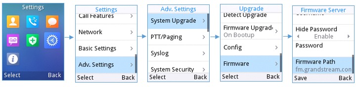
Configure via Web GUI
Open a web browser on PC and enter the IP address for the WP810/WP822/WP825. Then login with the administrator username and password. Go to Maintenance 🡪 Upgrade and Provisioning🡪 Firmware., enter the IP address or the FQDN for the upgrade server and choose to upgrade via TFTP, HTTP or HTTPS (The default setting is HTTPS). Save and apply the changes or reboot the phone for the upgrade process to begin.
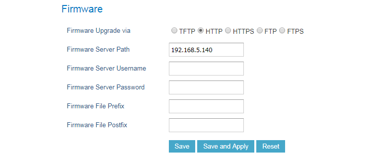
Local Firmware Servers
Instructions for local firmware upgrade via TFTP:
- Unzip the firmware files and put all of them in the root directory of the TFTP server.
- Connect the PC running the TFTP server and the WP810/WP822/WP825 device to the same LAN segment.
- Start the TFTP server and configure the TFTP server in the phone’s web configuration interface.
- Configure the Firmware Server Path on your WP810/WP822/WP825 to the IP address of the PC.
- Update the changes and reboot the WP810/WP822/WP825.
Provisioning and Configuration File Download
Grandstream SIP Devices can be configured via the Web Interface as well as via a Configuration File (binary or XML) through TFTP or HTTP/HTTPS. The “Config Server Path” is the TFTP, HTTP or HTTPS server path for the configuration file. It needs to be set to a valid URL, either in FQDN or IP address format. The “Config Server Path” can be the same or different from the “Firmware Server Path”.
A configuration parameter is associated with each field in the web configuration page. A parameter consists of a Capital letter P and 1 to 5 (could be extended to more in the future) digit numeric numbers. i.e. For a detailed parameter list, please refer to the corresponding firmware release configuration template in the following link: https://www.grandstream.com/support/tools
When the WP810/WP822/WP825 boots up, it will issue TFTP or HTTP(S) request to download a configuration XML file named “cfgxxxxxxxxxxxx” followed by “cfgxxxxxxxxxxxx.xml”, where “xxxxxxxxxxxx” is the MAC address of the phone, i.e., “cfg000b820102ab” and “cfg000b820102ab.xml”. If downloading “cfgxxxxxxxxxxxx.xml” file is not successful, the provision program will download a generic cfg.xml file. The configuration file name should be in lower case letters.
For more details on XML provisioning, please refer to the following document:
https://documentation.grandstream.com/knowledge-base/sip-device-provisioning-guide/
FACTORY RESET
Restore to Factory Default via LCD Menu
There are two methods to restore the WP810/WP822/WP825 to the factory default settings.
- On WP810/WP822/WP825 idle screen, go to Settings 🡪 Advanced Settings 🡪 Factory reset.
- In the new window, confirm the reset using the left softkey.
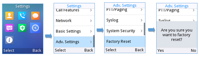
- Once confirming the factory reset, the phone will reboot with the default factory settings.
Restore to Factory Default via the Web GUI
- Login WP810/WP822/WP825 Web GUI and go to Maintenance 🡪 Tools.
- Click on the Start button in front of Factory Reset.

- A dialog box will pop up to confirm factory reset.
- Click OK to restore the phone to factory settings.
CHANGE LOG
This section documents significant changes from previous firmware versions. Only major new features or major document updates are listed here. Minor updates for corrections or editing are not documented here.
Firmware Version 1.0.11.60
- Disabled user account by default. [Enable User Web Access]
- Discard default user passwords. [Web UI Access Level Management]
Firmware Version 1.0.11.59
- No Major changes.
Firmware Version 1.0.11.57
- Added support VQ RTCP-XR. [VQ RTCP-XR]
- Added support to configure the static DNS SRV records. [Static DNS Cache]
- Add support for the On-Cradle Hang-up. [On-cradle Hangup]
- Added support Alert-Info header value under Match incoming caller ID feature. [Alert Info header]
- Changed the “Maximum Number of SIP Request Retries” default value to 2. [Maximum Number of SIP Request Retries]
Firmware Version 1.0.11.51
- Added support for on hold reminder tone. [On Hold Reminder Tone]
- Added The LDAP Named Filter Field to The LDAP Config. [LDAP Name Filter]
Firmware Version 1.0.11.43
- Added support for the remote ringtones. [Remote Ringtone via Alert Info]
- Added support for Trusted Domain Name. [Trusted Domain Name]
Firmware Version 1.0.11.40
- Added “Enable Live DialPad” and “Live DialPad Expire Time”. [Live DialPad]
- Added the prompt information while enable or disable the TR-069 function requires a restart to take effect. [Enable TR-069]
Firmware Version 1.0.11.34
- Added support for increased jitter buffer target delay. [VoWLAN Target Delay]
- Added support for 802.11k and 802.11v standards. [VoWLAN Target Delay]
- Added roam scan parameters. [Poor Signal Scan Interval and Roaming Signal Threshold]
- Added support for power saving. [Power save mode]
- Enhanced “Network Monitor” which supports MAC address on LCD. [Network status]
- Added support for disabling the DND mode. [Enable DND Feature]
- Added support for contact name format. [Contact name format]
- Added support for lock volume control. [Lock Speaker Volume]
- Added support set the volume from WebUI. [Speaker Ring Volume]
- Added support for Headset TX Gain. [Headset TX Gain]
- Added support for Headset RX Gain. [Headset RX Gain]
- Added support for Handset TX Gain. [Handset TX Gain]
Firmware Version 1.0.11.28
- Added support for reboot notification for certain if must reboot to apply settings. [Reboot Confirmation]
- Added support for different account ringtones without using Match Incoming Caller ID. [Account Ringtone and Default Ringtone]
- Added Support to configure F-timer and B-timer. [SIP Timer B Timeout] [SIP Timer F Timeout]
- Integrate new Digicert certificates in firmware. [Validate Server Certificates]
- Added the options to control the indicated LED pattern. [LED Control]
- Added support for factory resetting the security level. [Factory Reset Security Level]
- Added support for upgrade prompt bypass. [Disable Firmware Upgrade Confirmation]
- Added support to disable the Notification Tone. [Notification Tone]
- Added support for SIP messages tone. [SIP Message Alert Repeat Count]
- Added support for the Maximum Number of SIP Request Retries. [Maximum Number of SIP Request Retries]
- Added support for Failback Timer. [Failback Timer]
- Added the option “Saved one until failback timer expires” in DNS SRV Fail-over Mode. [Saved one until failback timer expires]
Firmware Version 1.0.11.22
- Added new feature to disable redial with # key. [Account/Call Settings]
- Added new feature to support for OpenVPN®. [Network/OpenVPN®]
Firmware Version 1.0.11.20
- Added new feature to support capture SSL Key Log File [With System Key Information]
- Added new features in Packet Capture monitor mode support. [Capture in Monitor Mode]
- Added 3CX Auto Provision option. [3CX Auto Provision]
- Added support to connect up to 20 SSIDs.
- Added door system support and GDS settings [Grandstream Door System]
- Added support for Off-hook Auto Dial. [Off-hook Auto Dial]
- Added support for Audio Control. [Audio Control]
Firmware Version 1.0.11.8
- Added new option “Enable TCP Keep Alive”. [Enable TCP Keep Alive]
- Added new option to enable/disable “Off-cradle Pickup”. [Off-cradle Pickup]
- Added new option to enable/disable call end tone. [Disable Call End Tone]
Firmware Version 1.0.11.2
- Added support for disable in-call DTMF display. [Settings/Call Features]
- Added support for WPA3 Wi-Fi security. [Network/Wi-Fi Settings]
- Added support for LDAP configuration. [Directory/LDAP]
- Added support for Allow Dial Through Popups. [Settings/General Settings]
- Added option “Use MAC Header” for account 1 and account 2. [Account/SIP Settings]
- Updated option “Use MAC Header” to “Add MAC in User-Agent” for account 1 and account 2. [Account/SIP Settings]
- Added support busy tone configuration to the web GUI. [Settings/Preferences]
Firmware Version 1.0.7.83
- No major changes.
- Added support for GDMS. [TR-069]
- Added support for Turkish language. [Multi-language]
- Added Japanese language support on LCD. [Multi-language]
- Update Wi-Fi Security type from “WPA PSK” to “WPA/WPA2 PSK”. [Security Type]
- Added support for “Feature Key Synchronization”. [Feature Key Synchronization]
- Added support for “Capture”. [Capture]
- Added support for “Matching Incoming Caller ID”. [Match Incoming Caller ID]
- Added support for TR-069 configuration. [TR-069]
- Added support for “Configuration via Keypad Menu”. [Configuration via Keypad Menu]
- Added support for “Register Before DNS SRV Failover”. [Register Before DNS SRV Failover]
- Added support for Minimum and Maximum TLS Version configuration. [Minimum TLS Version] [Maximum TLS Version]
- Added support for 802.11r. [802.11r]
- Added support to configure Country Code while configuring Wi-Fi from handset on the first time. [Country]
- Added support to differentiate rejected calls icon from missed calls. Now the rejected calls will be logged as received calls with different icon. [Icons Description]
- Added support to download a phonebook from the server [Directory/Phonebook Management].
- Added support for “Disable Recovery on Blind Transfer” [Disable Recovery on Blind Transfer].
- Added Multicast Listening setting fields for Multicast Paging settings on web UI [Multicast Listening].