
WELCOME
Thank you for purchasing Grandstream GDS3710/GDS3712.
The GDS3710 is an IP Video Door System that also serves as a high-definition IP surveillance camera and IP intercom to offer facility access control and security monitoring for buildings of all sizes. This powerful IP Video Door System offers a 180-degree video viewing angle for wall-to-wall coverage, has a built-in RFID chip reader for secure keyless entry, includes a built-in microphone and speaker to support intercom functionality, and offers alarm-in and alarm-out support for integration with existing security devices. The GDS3710 integrates with Grandstream’s free management utility software, GDS Manager, allowing RFID card information, video feeds as well as the device itself to be fully managed by this software. By being ONVIF Profile S compliant, the GDS3710 can be integrated with any third-party ONVIF-compliant surveillance or recording solution. Powered by an advanced Image Sensor Processor (ISP) and state-of-the-art image algorithms, the GDS3710 delivers 1080p FHD video resolutions and offers exceptional performance in all lighting conditions. It features SIP/VoIP technology with 2-way audio and video streaming feeds loaded directly to smartphones, SIP endpoints, and the GDS management software. The GDS3710 is equipped with integrated PoE for seamless installation, bright LEDs for illumination, a motion detector for security protection, a lighting control switch, and more. The combination of the GDS3710, Grandstream’s GXP21xx IP phones, GXV video phones, and Grandstream Wave mobile app provide a complete solution for access control, video intercom, and security needs.
The GDS3712 is a hemispheric IP Video Intercom System that also serves as a high-definition IP surveillance camera to offer facility access control and security monitoring for buildings of all sizes. Powered by an advanced Image Sensor Processor (ISP) and state-of-the-art image algorithms, it delivers exceptional performance without blind spots. The GDS3712 IP video intercom system features industry-leading SIP/VoIP for 2-way audio and video streaming to smartphones and SIP phones and the GDS management software. This system is equipped with integrated PoE for seamless installation, motion detection for security protection, a lighting control switch, Alarm Input/Output, and more . The GDS3712 can also be managed with GSURF Pro or any ONVIF-compliant video management system. It also offers a flexible HTTP API for easy integration with 3rd party applications and other surveillance systems. The combination of the GDS3712, Grandstream’s IP phones, video phones, and Wave mobile app provides a complete end-to-end solution for access control, video intercom, and security recording needs.
PRODUCT OVERVIEW
Feature Highlights
The following table contains the major features of the GDS3710 and GDS3712.
 |
|
 |
|
GDS3710/GDS3712 Features in a Glance
Technical Specifications
The following table resumes all the technical specifications including the protocols/standards supported, voice codecs, telephony features, and upgrade/provisioning settings for GDS371x.
- GDS3710
Video Compression | H.264 High Profile / Main Profile / Base Profile, Motion JPEG. |
Image Sensor Resolution | 1/2.7”, 2 Megapixel, 1920H x 1080V. |
Lens Type | 1/2”, F2.5, FOV: 180°(W) x 150°(H). |
Day & Night Mode | White LEDs with smart brightness control. |
Max Video Resolution | 1920×1080. |
Max Frame Rate | 30 frames per second. |
Minimum Illumination | 0.5Lux. |
Wide Dynamic Range | Yes, up to 120dB. |
Embedded Analytics | Motion detection. |
Snapshots | Triggered upon events, sent via email and/or FTP. |
Multi-stream Resolution | High-performance streaming server allowing multiple simultaneous accesses:
|
Network Protocols | TCP/IP/UDP, RTP/RTCP, HTTP/HTTPS local upload and mass provisioning using TR-069, ARP/RARP, ICMP, DNS, DHCP, SSH, SMTP, TFTP, NTP, STUN, TLS, SRTP. |
SIP/VoIP Support | Broad interoperability with most 3rd party SIP/VoIP devices and leading SIP/NGN/IMS platforms. |
Voice Codecs | G.711µ/a-law, G.722, G.729A/B, DTMF (RFC2833, SIP INFO), AEC. |
QoS | Layer 2 QoS (802.1Q, 802.1P) and Layer 3 QoS (ToS, DiffServ, MPLS). |
Security | User and administrator level access control, MD5 and MD5-sess based authentication, 256-bit AES encrypted configuration file, TLS, SRTP, HTTPS, 802.1Q. |
Upgrade / Provisioning | Firmware upgrade via TFTP/HTTP/HTTPS, mass provisioning using TR-069 or AES encrypted XML configuration file. |
Audio Input | Built-in Digital Microphone, up to 1.5m with AEC. |
Audio Output | Built-in HD Loudspeaker (2 Watt), sound quality suitable for up to 3 m. |
Keypad / Buttons | 12-key touchpad plus a capacitive doorbell button, each with individual LED illumination. |
RFID | 125KHz: EM4100 (1 RFID card and 1 RFID key fob included). |
Alarm Input | Yes, 2 channels, Vin < 15V, for door sensor or other devices. |
Alarm Output | Yes, 2 channels, 125VAC/0.5A, 30VDC/2A, Normal Open or Normal Close, for electric lock, light switch or other devices. |
Network Interface | 10M/100M auto-sensing. |
Expansion Interface | Wiegand (26 bits) input and output. |
Dimensions and Weight | 173mm(H) x 80mm(W) x 36mm(D). |
Power Supply | PoE (Power over Ethernet) IEEE 802.3af Class 3, or 12VDC/1A connection (AC power adapter not included). |
Interoperability | ONVIF (Profile S). |
Ingress Protection | Weatherproof, vandal resistant, with support for extra back reinforcing metal plate |
Temperature and Humidity | Operation: -30°C to 60°C (-22°F to 140°F) |
Protection Class | IP66 (EN60529), IK09 (IEC62262). |
Compliance | FCC: Part 15 subpart B Class B; Part 15 C; MPE |
GDS3710 Technical Specifications
- GDS3712
Video Compression | H.264 High Profile / Main Profile / Baseline Profile, Motion JPEG. |
Image Sensor Resolution | 1/2.7”, 2 Megapixel, 1920H x 1080V. |
Lens Type | 1/2”, F2.5, FOV:180°(W) x 150°(H). |
Max Video Resolution | 1920×1080. |
Max Frame Rate | 30 frames per second. |
Minimum Illumination | 0.5Lux. |
Wide Dynamic Range | Yes, up to 120dB. |
Video Bit Rates | 128 Kbps to 4 Mbps, multi-rate for preview & recording. |
PoE | IEEE 802.3af Class 3. |
Embedded Analytics | Motion detection (up to 4 privacy masks). |
Snapshots | Triggered upon events, sent via email and/or FTP. |
Multi-stream Resolution | High-performance streaming server allowing multiple simultaneous accesses:
|
Network Protocols | TCP/IP/UDP, RTP/RTCP, HTTP/HTTPS local upload and mass provisioning using TR-069, ARP/RARP, ICMP, LLDP-MED, DNS, DHCP, SSH, SMTP, TFTP, NTP, STUN, TLS, SRTP. |
SIP/VoIP Support | Broad interoperability with most 3rd party SIP/VoIP devices and leading SIP/NGN/IMS platforms. |
Voice Codecs | G.711µ/a-law, G.722, G.729A/B, DTMF (RFC2833, SIP INFO), AEC. |
QoS | Layer 2 QoS (802.1Q, 802.1P) and Layer 3 QoS (ToS, DiffServ, MPLS). |
Security | User and administrator level access control, MD5 and MD5-sess based authentication, 256-bit AES encrypted configuration file, TLS, SRTP, HTTPS, 802.1Q. |
Upgrade / Provisioning | Firmware upgrade via TFTP/HTTP/HTTPS, mass provisioning using TR-069 or AES encrypted XML configuration file. |
Audio Input | Built-in microphone, up to 1.5m with AEC |
Audio Output | Built-in HD Loudspeaker (2 Watt), sound quality suitable for up to 3 m. |
Button | 1 call button with Blue LED backlight |
Alarm Input | 2 Optocoupler Input, Vin < 15V, for door sensor or another low voltage device. |
Alarm Output | 2 Relay, 125VAC/0.5A or 30VDC/2A, Normal Open or Normal Close, for electric lock, light switch, or other device. |
Network Interface | 10M/100M auto-sensing. |
Dimensions and Weight | On-Wall: 173mm(H) x 80mm(W) x 36mm(D); |
Power Supply | PoE (Power over Ethernet) IEEE 802.3af Class 3, or 12VDC/1A connection (AC power adapter not included). |
Ingress Protection | Weatherproof, vandal resistant, with support for extra back reinforcing metal plate. |
Temperature and Humidity | Operation: -30°C to 60°C (-22°F to 140°F) |
Protection Class | IP66 (EN60529), IK09 (IEC62262). |
Compliance | FCC: Part 15 subpart B Class B; Part 15 C; MPE |
GDS3712 Technical Specifications
GETTING STARTED
This chapter provides basic installation instructions including the list of the packaging contents and information for obtaining the best performance using the GDS371x Video Door System.
Equipment Packaging
GDS3710
|
|

GDS3712
|
|

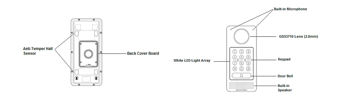
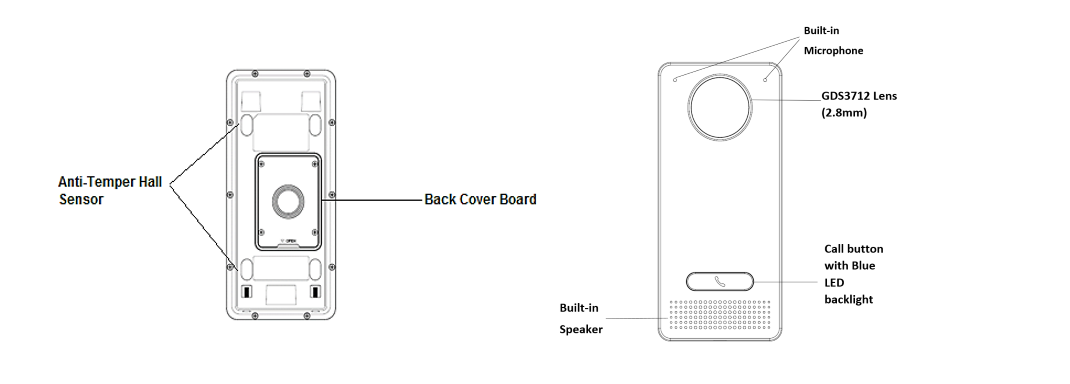
Description of the GDS371x
Below figures show the component of the back and front view of GDS371x IP Video Door System:
GDS3710
GDS3712
Connecting and Setting up the GDS371x
The GDS371x can be powered using PoE or PSU:
Using PoE as power supply (Suggested)
- Connect the other end of the RJ45 cable to the PoE switch.
- PoE injector can be used if PoE switch is not available.
Using the power adapter as power supply (PSU not provided)
- Connect the other end of the RJ45 cable to network switch or router.
- Connect DC 12V power source via related cable to the corrected PIN of the GDS371x.
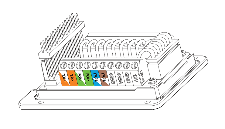
GDS371x Wiring Connection
Jack | Signal | Function | Note | |
J2 (Basic) 3.81mm | TX+ | Ethernet | Orange / White | Data |
TX- | Orange | |||
RX+ | Green / White | |||
RX- | Green | |||
PoE_SP2 | Blue + Blue/White | Please twist these two wires together and connect to SP1, SP2 respectively even the PoE NOT used. | ||
PoE_SP1 | Brown + Brown/White | |||
GND | Power Supply | DC 12V, 1A Minimum | ||
12V | ||||
J3 (Advanced) 3.81mm | GND | Alarm GND | ||
ALARM1_IN+ | Alarm In | Vin<15V | ||
ALARM1_IN- | ||||
ALARM2_IN+ | ||||
ALARM2_IN- | ||||
NO1 | Alarm Out | Relay: 30VDC/2A; 125VAC/0.5A | ||
COM1 | ||||
NO2 | Electric Lock | For "Fail Secure" (Locked when Power Lost) Strike, connect COM2 & NO2. For "Fail Safe" (Open when No Power) Magnetic Lock, connect COM2 & NC2. Relay: 30VDC/2A; 125VAC/0.5A | ||
COM2 | ||||
NC2 | ||||
J4 (Special) 2.0mm | GND | Wiegand Power GND | Black | Both Input and Output MUST be connected |
WG_D1_OUT | Wiegand Output Signal | Orange | GDS3710 function as Output of Card Reader, Connect Pin 1, 2, 3 | |
WG_D0_OUT | Brown | |||
LED | Wiegand Output LED Signal | Blue | For External Card Reader; Or GDS3710 as Receiver Only | |
WG_D1_IN | Wiegand Input Signal | White | For External Card Reader | |
WG_D0_IN | Green | |||
BEEP | Wiegand Output BEEP Signal | Yellow | For External Reader Only | |
5V | Wiegand Power Output | Red | For External Card Reader Only. | |
GDS371x Wiring Connection
GDS371x Back Cover Connections

Connection Example
To connect the GDS either by using PoE or PSU follow steps below:
- Open the Back-Cover Board of the GDS371x which should look like following figure.
Power the unit using PoE
- Cut into the plastic sheath of your Ethernet cable, then Unwind and pair as shown below.
Use the TIA/EIA 568-B standard, which define pin-outs for using Unshielded Twisted Pair cable and RJ-45 connectors for Ethernet connectivity.
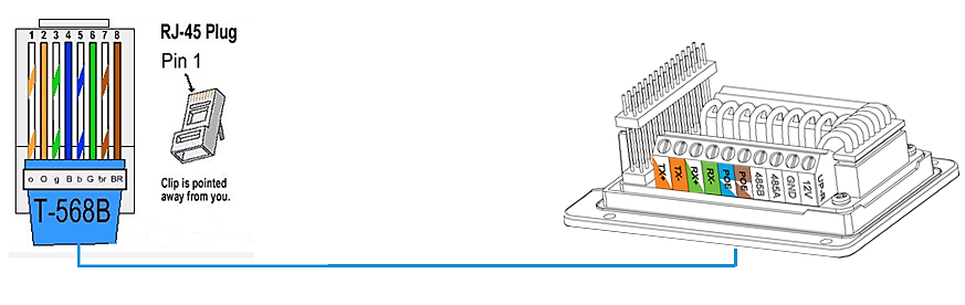
- Connect each wire of the cable to its associate on the Back Cover of the GDS371x to power the unit using PoE.
Power the unit using PSU
- To power the unit using PSU, use a multimeter to detect the polarity of your Power Supply, then connect GND to negative pole and 12V to positive pole of the PSU.

GETTING TO KNOW GDS371x
The GDS371x has an embedded Web server to respond to HTTP/HTTPS GET/POST requests. Embedded HTML pages allow users to configure the GDS371x through Microsoft Internet Explorer or Mozilla Firefox.
Download WebControl Plug-in from the GDS371x WebGUI. For Apple platform OS-X, only MJPEG video codec supported currently.
Connecting GDS371x to Network with DHCP Server
The GDS371x by default has a DHCP client enabled, it will automatically get IP address from DHCP server.
Windows Platform
Two ways exist for Windows user to get access to the GDS371x:
UPnP
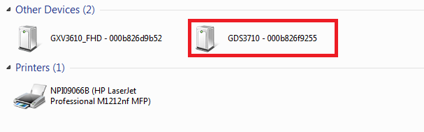
By default, the GDS371x has the UPnP feature turned ON. For customers using Windows network with UPnP turned on (most SOHO routers support UPnP), it is very easy to access the GDS371x , in this example we will take the GDS3710 as our testing unit:
- Find the “Network” icon
 on the windows Desktop.
 - Click the icon to get into the “Network”, the GDS3710 will list as “Other Devices” shown like below. Refresh the pages if nothing displayed. Otherwise, the UPnP may not be active in the network.
3. Click on the displayed icon of related GDS3710, the default browser (e.g.: Internet Explorer, Firefox or Chrome) will open and connect directly to the login webpage.
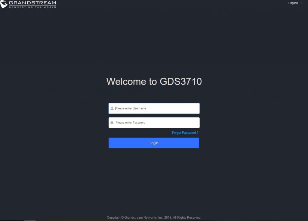
4. Once logged in, the prompt message will display asking for plug-in installation.
5. Disable security or antivirus software, download and install the plug-in, close and open the browser again, the embedded video will be displayed if clicking the “LiveView” and pressing the stream number.
GS Search
GS search is a program that is used to detect and capture the IP address of Grandstream devices, below are instructions for using the “GS Search” utility tool:
- Download the GS Search utility tool from Grandstream website using the following link: GS_Search
- Double click on the downloaded file and the search window will appear.
- Click on
 button to start the discovery for Grandstream devices.
 - The detected devices will appear in the output field like below.
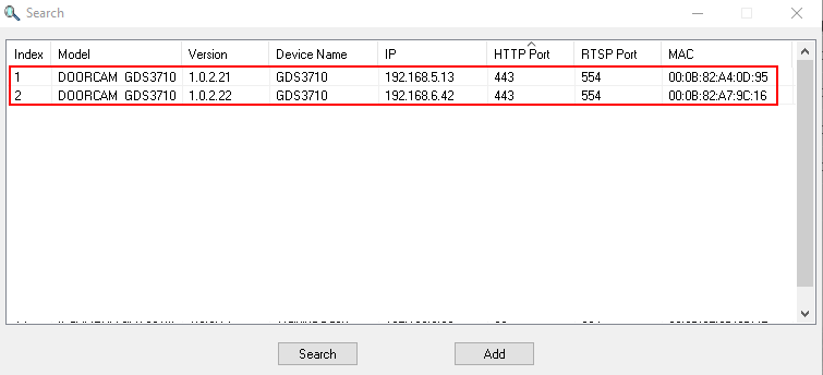
5. Double click on a device to access its webGUI.
GDS Manager Utility Tool
User can know the IP address assigned to the GDS371x from DHCP server log or using the Grandstream GDS Manager after installing this free utility tool provided by Grandstream. User can find instructions below, for using “GDS Manager” utility tool:
- Download the GDS Manager utility tool from Grandstream website using the following link: GDSManager Download
- Install and run the Grandstream GDS Manager, a client/server architecture application, the server should be running first, then GDSManager (client) later:


3. On the GDS Manager access to Device 🡪 Search and Click on the ![]() button to start device detection
button to start device detection
4. The detected devices will appear in the output field like below:
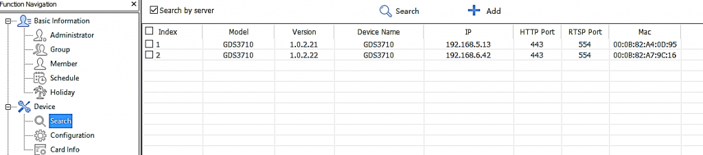
5. Double click the column of the detected GDS371x, the browser will automatically open and show the device’s web configuration page.
6. The browser will ask for plug-in if not installed, please authorize the installation of the plug-in.
7. Enter the administrator user name and password to access the Web Configuration Interface, the default admin username is “admin” and the default random password can be found at the sticker on the GDS371x.
8. The plug-in can be downloaded from the GDS371x Web GUI.
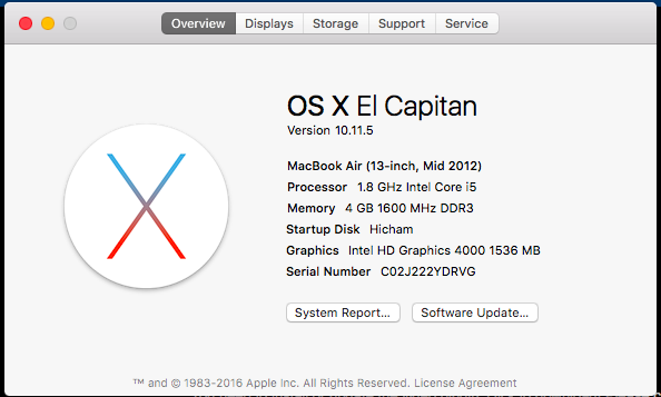
Apple Platform
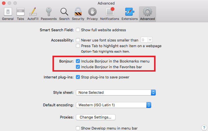
For Apple users, please turn on Bonjour of Safari to find and access the GDS371x.
- Open Safari, select “Advanced” to open the Advanced Setting.
- Click “Include Bonjour in the Bookmarks menu” and “Include Bonjour in the Favorites bar” then close the setting page and back to Safari.
3. Bonjour will now display embedded at Safari. Select “Bonjour” pull-down menu and select “Webpages”, the related device like GDS371x will be there.
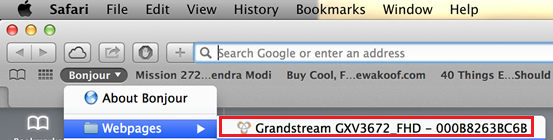
4. Click on the displayed GDS371x to access to the configuration page of the GDS371x.
5. To see the MJPEG video stream, users should type in the browser the following URL while specifying the correct protocol (either HTTP or HTTPs and the correct port number) : http(s)://IP_address_GDS:Port/jpeg/mjpeg.html
Notes:
- The instructions provided above are based on Safari/OS-X, other Apple platform like iOS (iPhone/iPad) can use similar method.
- iPhone/iPad (iOS) users are recommended to use Applications in Apple Store.
- Free or Paid applications from Apple Store like “IP Cam Viewer” is suggested and verified working with Grandstream GDS371x.
- Apple Store applications like “IP Cam Viewer” will support H.264 video codec.
Connect to the GDS371x using Static IP
If there is no DHCP server in the network, or the GDS371x does not get IP from DHCP server, user can connect the GDS371x to a computer directly, using static IP to configure the GDS371x.
- The default IP, if no DHCP server, or DHCP request times out (after 3 minutes), is 192.168.1.168
- Connect the Ethernet cable from GDS371x to the computer network port directly.
- Configure the computer using Static IP: 192.168.1.XXX (1<XXX<255, except for 168) and configure the “Subnet mask” to “255.255.255.0”. Leave the “Default Gateway” to “Blank” like below:

4. Power on the GDS371x, using PoE injector or external DC power.
5. Enter 192.168.1.168 in the address bar of the browser, log in to the device with admin credentials. the default admin username is “admin” and the default random password can be found at the sticker on the GDS371x.
6. The browser will ask for plug-in or ActiveX if not installed, otherwise it will get to Home page and show web interface of GDS371x.
7. Access the Web Configuration Interface. Internet Explorer will indicate that “This website wants to install the following add-on: GSViewerX.cab from Grandstream Networks Inc.”, allow the installation.
GDS371x APPLICATION SCENARIOS
The GDS371x Door System can be used in different scenarios.
Peering Mode without SIP Server
For environment like remote warehouse/storage, grocery store, small (take-out) restaurants, just using static IP with PoE switch to form a LAN, using Grandstream’s video phone GXV3x50 or GXV3x70, the GDS371x will meet your very basic intercom, open door and surveillance requirement.
This is the solution to upgrade the traditional analog Intercom and CCTV security system. All you need is a Power source, Switch or PoE Switch and Grandstream GXV33xx or GXV34xx video phones.
The equipment list can be found below:
- GDS371x
- GXV33xx or GXV34xx
- PoE Switch with related Cat5e/Cat6 wiring
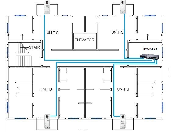
Peering using SIP Server (UCM6XXX)
For large deployment, multiple GDS371x might be required, peered connection will not work in such case due to multiple connections. Such scenarios require an IPPBX or a SIP Proxy to accomplish the tasks.
If remote access is required, a router with internet access should be added to below-needed equipment list:
- Several GDS371x
- UCM6XXX or another SIP Server
- GXV33xx or GXV34xx Video Phones
- PoE Switch with related Cat5e/Cat6 wiring
- Electronic Lock
If remote access to the GDS371x is required for viewing live video stream, Internet access is required and more equipment such as:
- Router.
- Internet Access (Optical fiber, 3G, 4G, Cable or DSL).
- iPhone or Android phone with 3rd party applications (IP Cam Viewer for instance).
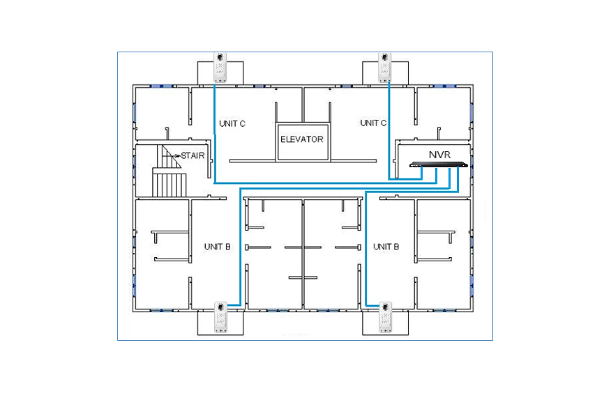
Using a Network Video Recorder (NVR)
For implementation with more than two GDS371Xs, if local video recording is required to store the record, then an NVR will be added to save all the video streams when people enter the door.
Equipment List:
- Several GDS371x
- NVR supporting Onvif Profile S.
- PoE switches with Cat5e/Cat6 wiring.
- Router.
- Internet Access (Optical fiber, 3G, 4G, Cable or DSL).
- iPhone or Android phone with 3rd party APP.
GDS371x PERIPHERAL CONNECTIONS
Below is the illustration of GDS371x peripheral connections for related applications, We will take the GDS3710 as our testing unit.
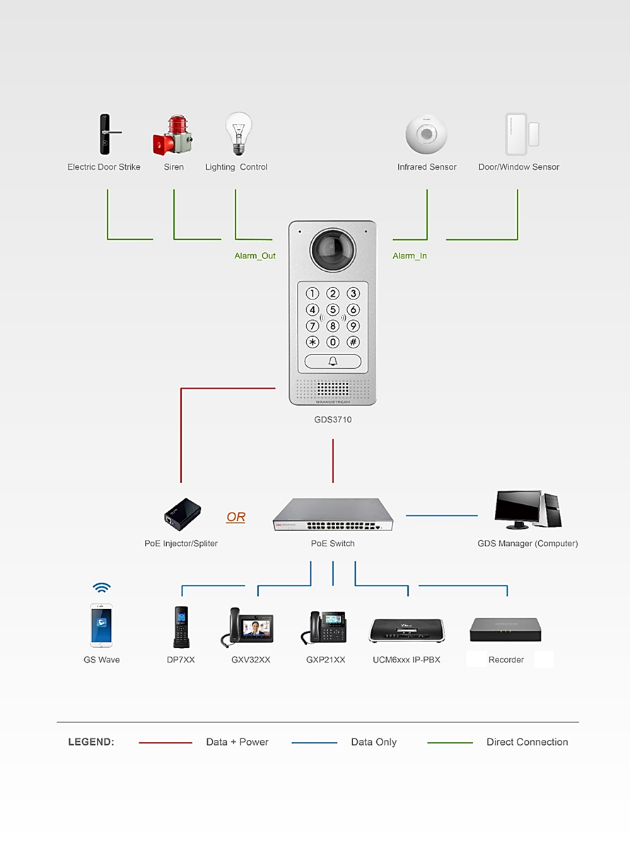
Alarm IN/OUT
Alarm_In could use any 3rd party Sensors (like IR Motion Sensor).
Alarm_Out device could use 3rd party Siren and Strobe Light, or Electric Door Striker, etc.
The figure below shows illustration of the Circuit for Alarm_In and Alarm_Out.
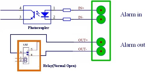
Notes:
- The Alarm_In and Alarm_Out circuit for the GDS371x should meet the following requirement:
Alarm Input | 3V<Vin<15V, PINs (1.02KΩ) |
Alarm Output | 125VAC/0.5A, 30VDC/2A, Normal Open, PINs |
- The Alarm_In circuit, if there is any voltage change between 3V and 15V, as specified in the table above, the GDS3710 Alarm_In port will detect it and trigger the action and event.
- Higher voltage and wrong polarity connections are prohibited because this will damage the devices.
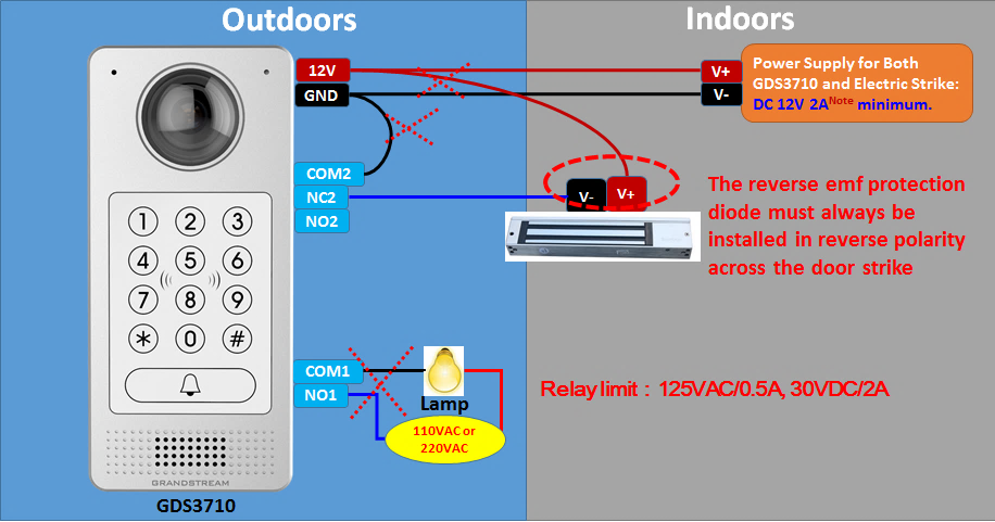
Protection Diode
When connecting the GDS371x to a door strike it is recommended to set an EMF protection diode in reverse polarity for a secure use, below examples of deploying the GDS3710 for the protection diode.
The reverse EMF protection diode must always be installed in reverse polarity across the door strike.
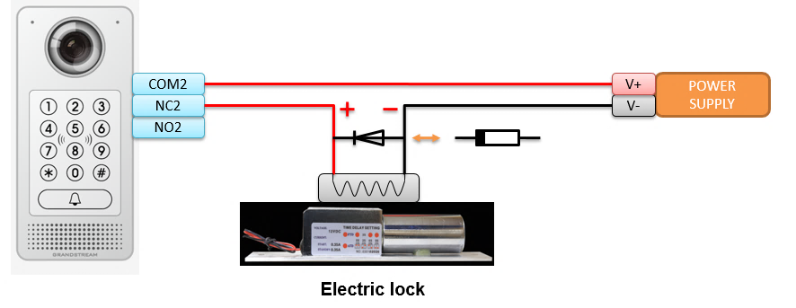
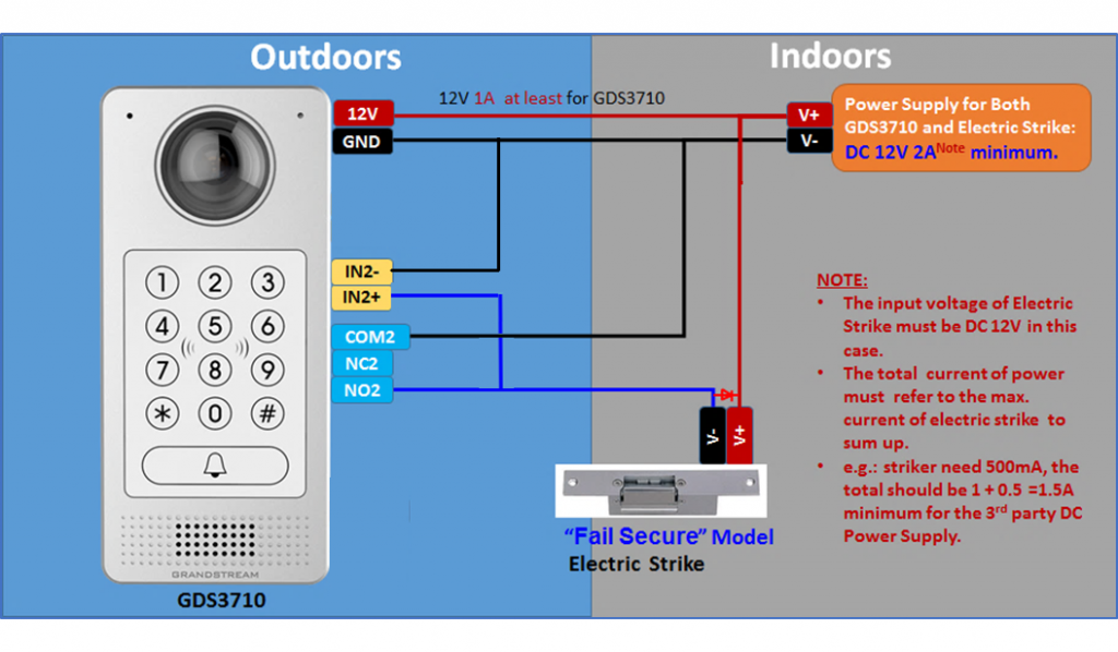
Connection Examples
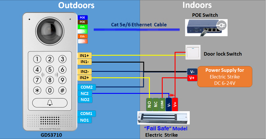
Below examples, show how to use wiring on the back cover of the GDS3710 to connect with external devices. The “NO” (Normal Open) model strike is used as example, “NC” (Normal Closed) should be similar and users need to decide which model (NO or NC) to be used on the door.
Wiring Sample using 3rd Party Power Supply
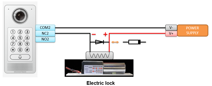
Wiring Sample using Power Supply for both GDS371x and Electric Strike
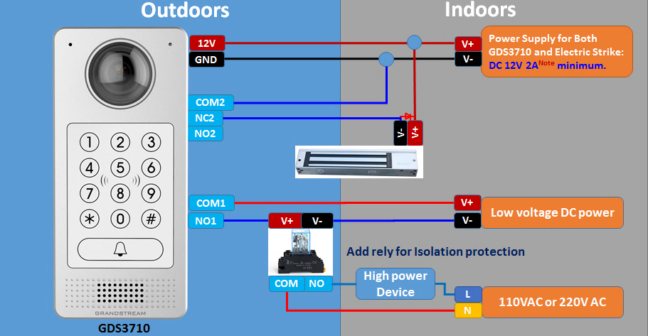
Wiring Sample using PoE to power GDS371x and 3rd Party Power Supply for Electric Strike
Good Wiring Sample for Electric Strike and High-Power Device
Wiegand Module Wiring Examples
GDS3710 package is shipped with one Wiegand cable for Input/Output Wiegand connections. The following examples shows how to connect the Wiegand Input/Output devices to the GDS3710.
Input example with 3rd party power supply for Wiegand device
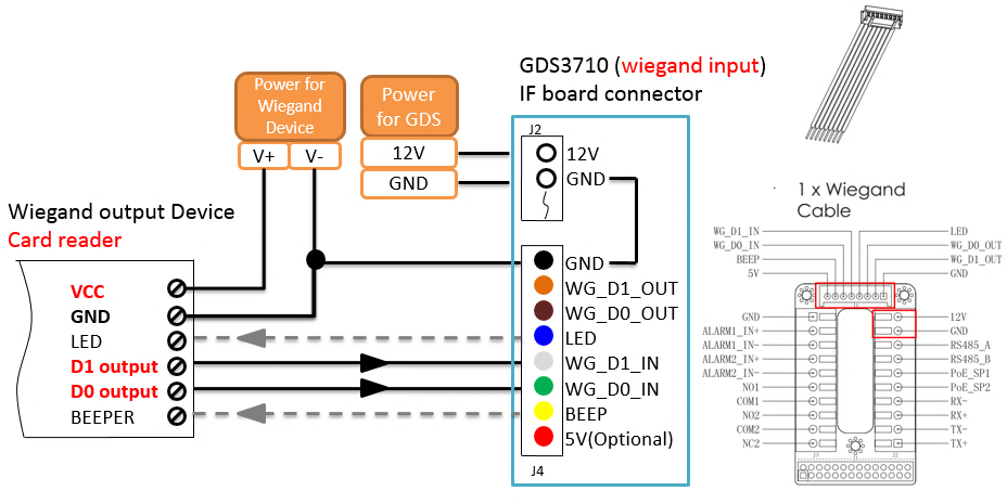
Make sure to connect the GND of the Wiegand device and the GDS3710 Wiegand port.
For Wiegand input mode, LED and Beep pins require that the Wiegand device support those interfaces. These two pins will not affect the Wiegand bus when not connected.
Input example with power supply for both GDS371x and Wiegand device

If power source is 12VDC, Wiegand device can share same power source of GDS3710. However, users need to check the max power consumption and the max capability of the power source.
If Wiegand device is using 5VDC, GDS3710 Wiegand port can provide 5VDC with max 500mA to power up Wiegand device.
Output example with 3rd party power supply for Wiegand device
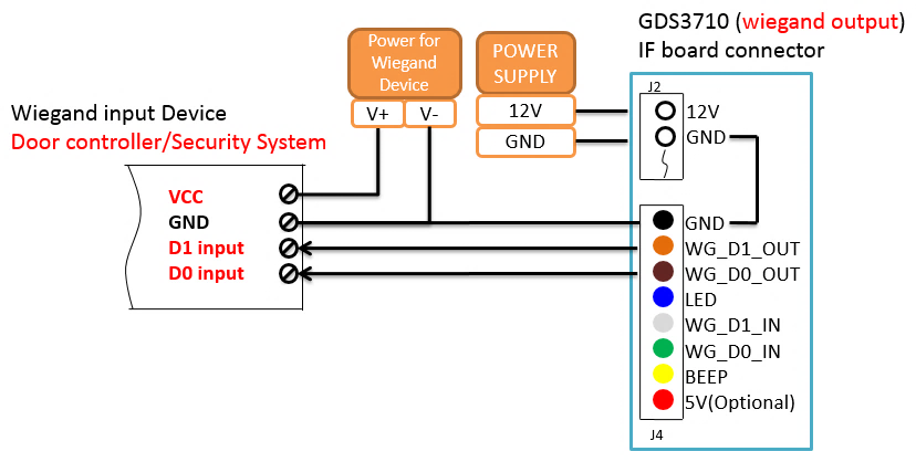
When the Wiegand output of the GDS3710 is connected, it acts as the signal receiver of the 3rd party Wiegand device, connecting to door controller. The major wiring is GND, D0, and D1. Because usually the door controller will consume big current and power, the power supply should be separated.
Wiegand RFID Card Reader Example

Siren alarming when door opened abnormally
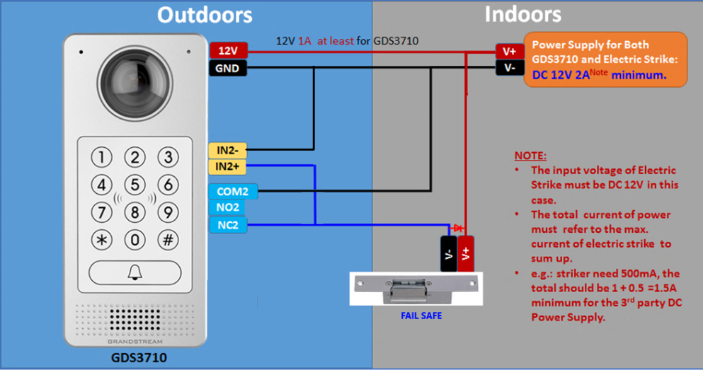
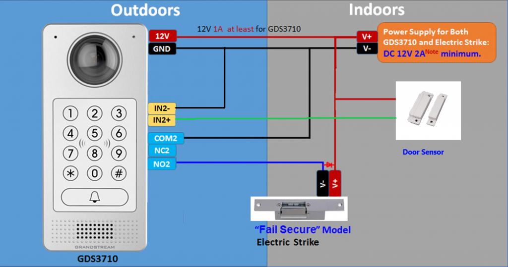
When this feature enabled (special wiring required, see below wiring diagram), abnormal open door will be detected by DI port (Alarm_In2 or IN2 in below diagram showed) if wired correctly (connecting the COMx port to DIx port) therefore trigger siren alarm. Once abnormal open door alarm triggered, the siren will sound non-stop, until manually override by related person.
There are several ways to stop and disable the alarm:
1) Power cycle the GDS37xx
2) Pick up the Alarm Phone Call (if configured)
3) Open Door using PIN (either public PIN or private PIN , Option valid only for the GDS3710 Model)
Once alarm triggered, the GDS371x will take snapshots when the abnormal open door happened, email and upload the snapshots to FTP or Central Server (when configured); call the configured alarm SIP phone, send the alarm output (if connected). User will only be able to disable the siren using the 3 methods mentioned above.
Detailed action information please refer to GDS37xx User Manual, “Alarm Action Settings” configuration.
Below are some diagrams showing the correct wiring to enable this new security enhancement feature:
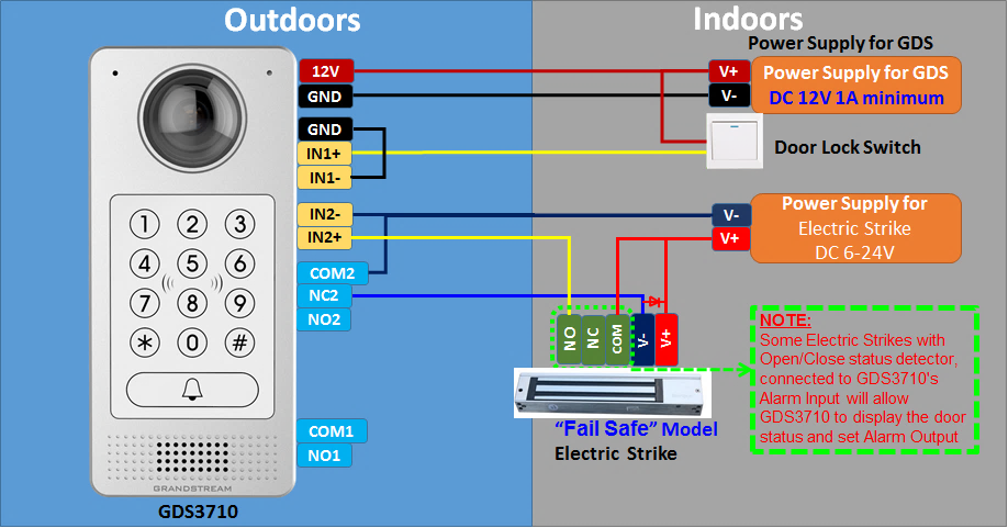
GDS371x Connection: IN2 set as Normal Close and “Fail Safe” Electric Strike using 3rd Party Power Supply
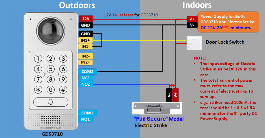
GDS371x Connection: IN2 set as Normal Open and “Fail Secure” Electric Strike using 3rd Party Power Supply
GDS371x Connection: IN2 set as Normal Open and “Fail Secure” Electric Strike using 3rd Party Power Supply with Door sensor
GSC3570 Secure Open Door via GDS37XX/GSC3570 Peering
This secure open door new feature is a major enhancement to GDS37xx, but need to include GSC3570 to make it a whole solution. The GDS37xx/GSC3570 will be peering together in LAN/WAN via IP/SIP, the door lock/strike will be wired to GSC3570 Alarm_Out port and controlled by GSC3570. This way the strike control is inside the building with enhanced security. Below is a setup example:
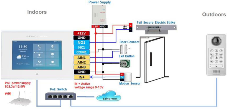
The GDS37xx can be powered via PoE, the GSC3570 can connect to same network via PoE or WiFi. For open door combination with GSC3570 and GDS37xx, if GSC3570 needs to control multiple GDS37xx, it has to use SIP and the related GDS37xx will control the strike/lock. The different GDS37xx doorbell call will have“ One Button Open Door” displayed when in “Preview” (early media support) or when call established.
The GSC3570 user will press the virtual button on touch screen to remotely open the door controlled by the related GDS37xx.There is no door limitation for such usage but only ONE DOOR can be opened at one time. It is just a SIP call open door application, but strike/lock control circuit is located outdoor.
For “Secure Open Door”, the GSC3570 is peering with GDS37xx. The GSC3570 controlling the relay/strike/lock from inside the building (Unlike GDS37xx installed outside), but only ONE door can be controlled because GSC3570 only has one Relay Control circuit build in.
This peering can be via LAN/WAN but LAN is recommended and actually most of the application scene are in LAN environment because most likely the GSC3570 and GDS37xx are in the same building. Although SIP/UCM over Internet/WAN also works, it is recommended to use static IP if the GSC3570 (inside) and GDS37xx(outside) are at same location in the same LAN.
This setup is much simple and reliable in case there is network outage like Internet/UCM is down.
For the GSC3570 and GDS37xx peering, it can be used via SIP only (Cloud or UCM); IP only (No SIP proxy or UCM but static IP address) and Mixed (SIP and fallback to IP if Proxy failed).
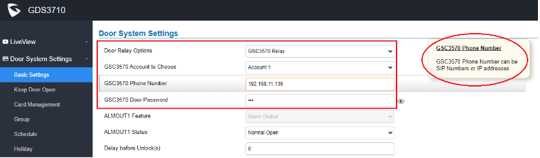
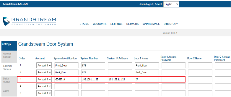
GDS3710 Web Configuration
This setup can be found under device web UI→Door System Settings →Basic Settings:
GSC3570 Web Configuration
The GSC3570 side also need to be configured according, like below:
Then we will be configuring the Digital Input on the GSC3570 as the figure below:

One-Way Interlocking Mode
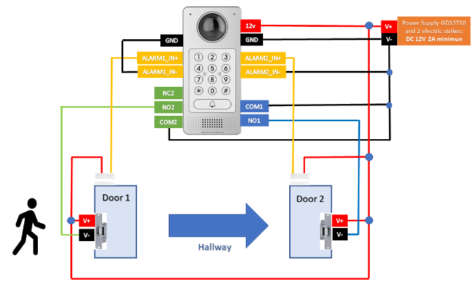
This feature will allow GDS3710 to control two doors in one direction, with additional 3rd party window/door sensor installed accordingly (not provided by Grandstream). When configured and wired correctly, the two doors will operate under a controlling logic as below:
1) Only legal PIN or RFID card can open door when BOTH doors are detected closed. ( Only for GDS3710 Model )
2) When 1st door opened by valid user, the 2nd door is and will remain closed; the 2nd door will automatically open once detected the 1st door closed and programmed timer reached.
3) When 2nd door opening, the 1st door will NOT open even a valid PIN/RFID used. ( Only for GDS3710 Model )
4) If entering 1st door and after 1st door closed and 2nd door opened, the person failed to enter 2nd door promptly (after 2nd door opening time out) will be locked in between two doors until next transaction happens or ask help (e.g.: call posted number or press button if there is one) from security staff to open door remotely (via SIP call into GDS3710 or GDSManager, for example).
This open door logic will make sure two doors are open in “One-Way” direction, at any given time only one door can be opened, and only one legal open door request is allowed to execute.
The hallway or scene between two doors could be monitored by installing Grandstream IP cameras.
This feature can be used in application scene like: College Dorm, Bank Branches, Government Offices, Medical Clinics, Private Clubs, etc., where there are two doors in place, high security and flow control is required (only one entry per time) but security guard may not be on site always.
Below is the illustrated drawing of the application scene as well as the wiring sample:
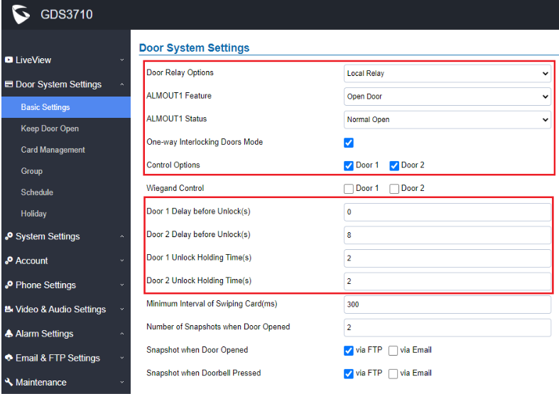
Web Configuration
This option can be found under device web UI→Door System Settings. Below example configuration screenshots are for reference only, customers need to test and get own parameters in field:
Digital Input to Check Door Status (Door 1 & Door 2)
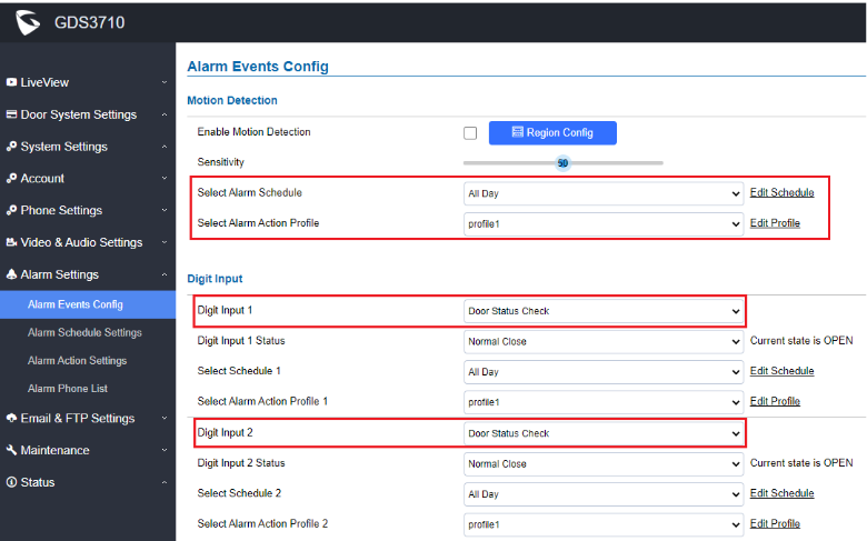
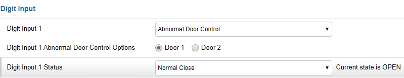
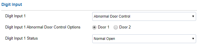
Proceed to Alarm Settings →Alarm Events Config →Digit Input, configured as follow:
- Digit Input 1: Door Status Check. The DI will validate the current status of the Door, whether it is close or open, based on the sensor signal sending to the “Digit input 1.
- Digit Input 1 Status: If set to Normal Open: Configured door status check will be triggered when Digital Input Status switch from Close to Open, If set to Normal Close: Configured door status check will be triggered when Digital Input Status switch from Open to Close. By default, Input Digit 1 Status is “Disabled”.
- Digit Input 2: Door Status Check. The DI will validate the current status of the Door, whether it is close or open, based on the sensor signal sending to the “Digit input 2”.
- Digit Input 2 Status: If set to Normal Open: Configured door status check will be triggered when Digital Input Status switch from Close to Open, if set to Normal Close: Configured door status check will be triggered when Digital Input Status switch from Open to Close. By default, Input Digit 2 Status is “Disabled.
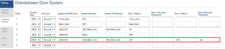
Open Door via GDS37xx with or without a SIP Call
This feature needs related matching GDS37XX firmware to work. The minimum firmware version needed:
- GDS3710: 1.0.7.19 or higher.
- GDS3705: 1.0.1.13 or higher.
From GDS37XX side, the configuration is the same. Only difference is the number of doors be controlled: If using Local Relay controlled by GDS37XX, TWO DOORS can be controlled.
If using GSC3570 Relay, ONLY ONE DOOR can be controlled. The PIN and other settings are the same as SIP remote open door or GSC3570 secure open door for the GDS3710.
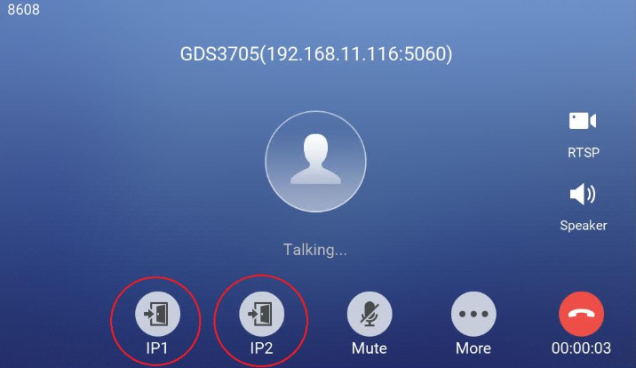
The difference will come out at the touch screen UI operation of GSC3570.

Door opening with SIP Call:
When GSC3570 established call with GDS37XX, the screen will display virtual open door button(s), and user will press the button to open door:
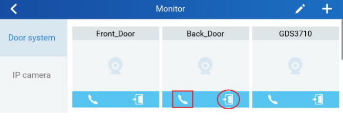
GSC3570 Open Door NO SIP Call:
At the GSC3570 idle screen, press “Monitor →Door system”, the related GDS37XX will be displayed. In the blue bar, left is a “Phone”icon and right is the “Open door”icon. The“Phone”icon will establish SIP call as previous firmware behaved.
Press “Open door” icon, the GSC3570 will open door directly and NO SIP CALL will be established. Depending on how many doors controlled, if one door configured, the door will open directly; if two doors configured, another screen will pop up to allow user to choose which door to open, as shown below:
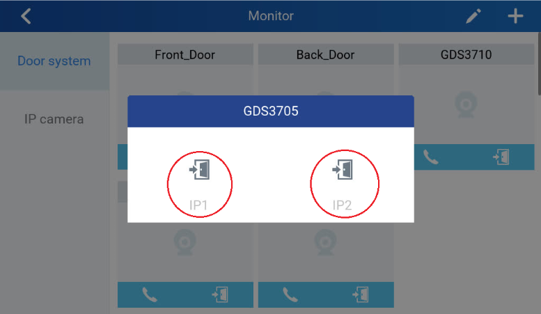
When the door is successfully opened the following message will appear:

GDS371x HOME WEB PAGE
Once logged in successfully to the GDS371x, user will see the following page.
Note: the options displayed might differ from browser to another, and from a GDS model to another (GDS3710/GDS3712)
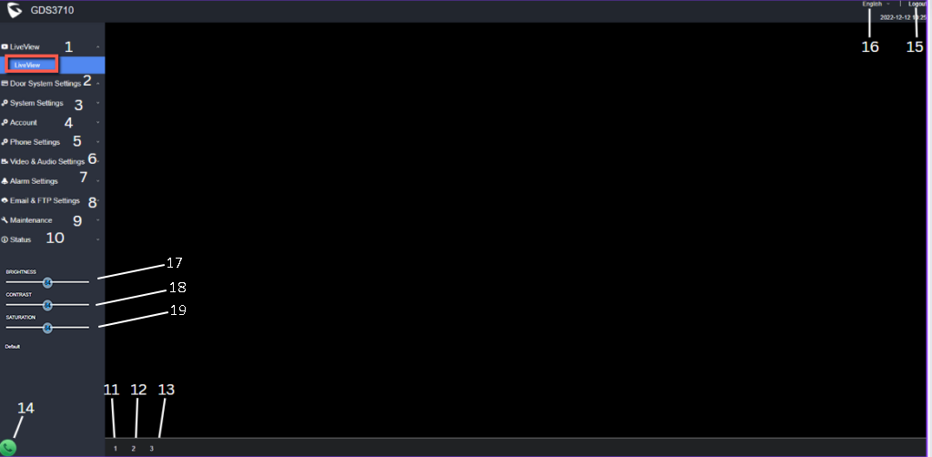
Number | Fields | Description |
1 | LiveView | Access to live view stream page. |
2 | Door System Settings | Access to “Door System Settings” page. |
3 | System Settings | Access to “System Settings” page. |
4 | Account | Access to “Account” configuration page. |
5 | Phone Settings | Access to “Phone Settings” configuration page. |
6 | Video & Audio Settings | Access to “Video & Audio settings” page. |
7 | Alarm Settings | Access to “Alarm settings” page. |
8 | Email & FTP Settings | Access to “Email & FTP Settings” page. |
9 | Maintenance | Access to “Maintenance” page. |
10 | Status | Click to enter “Status” page. |
11 | Stream 1 | Play the primary stream. |
12 | Stream 2 | Play the secondary stream. |
13 | Stream 3 | Play the third stream. |
14 | Calling interface | Allows to dial an extension from the web interface and select an account to place the call |
15 | Logout | Logout from the web page. |
16 | Language | Select the webpage language. |
17 | Brightness | Adjusts the live preview brightness |
18 | Contrast | Adjusts the live preview contrast |
19 | Saturation | Adjusts the live preview saturation |
Home Page Description
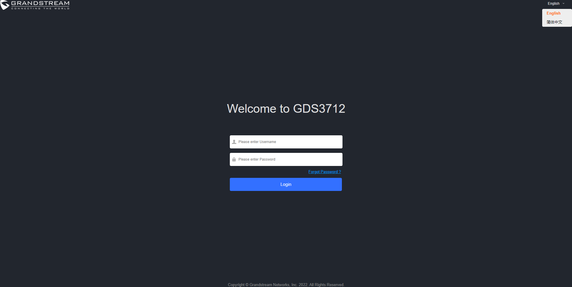
GDS371x Configuration & Language Page
- Once the IP address of the GDS371x is entered on the user browser, the login web page will pop up allowing user to configure the GDS371x parameters.
- When clicking on the “Language” drop down, supported languages will be displayed as shown in Figure below. Click to select the related webpage display language.
GDS371x SETTINGS
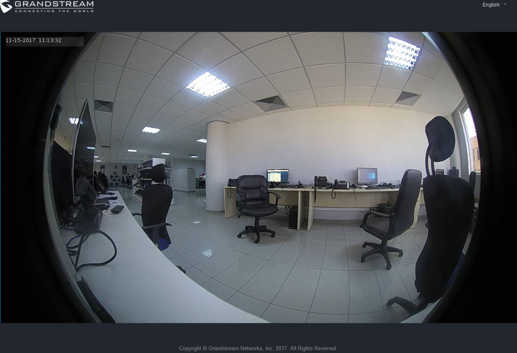
Live View Page
This page allows users to view the live video of the GDS371x using popular browsers like Chrome or Firefox immediately without downloading and installing any plugins.
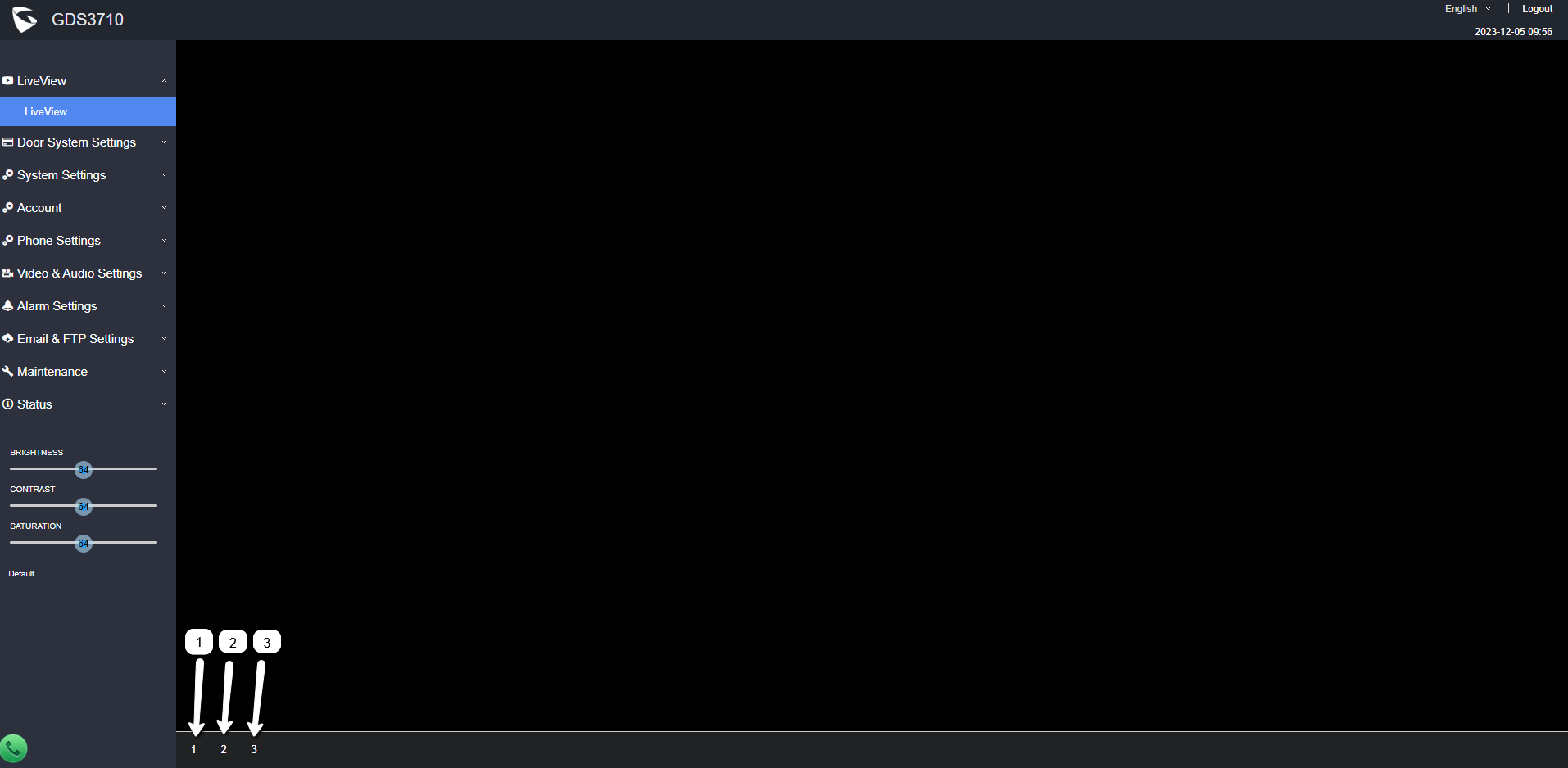
Three streams are available:
- 1 => Primary video stream: 1920*1080 resolution, recommended for continuous full HD recording.
- 2 => Secondary video stream: 640*480 resolution (1280 x 720 resolution for GDS3712), recommended for SIP/VoIP video calls (if used with GXV3470/GXV3480).
- 3 => Third video stream: 320*240 resolution, recommended for smartphone or Tablet Apps (IP Cam Viewer for instance).
Live Snapshot
Users can take view snapshots from GDS371x live view via HTTP API, this can be used without installing the any browser plugin. Starting from firmware 1.0.3.34, users can deploy two methods to view snapshots depending on JPEG Authentication Mode, which can be set under following path:
Web UI 🡺 System Settings 🡺 Access Settings

1). Challenge+Response MJPEG Authentication Mode:
Please follow below steps in order to take a snapshot via HTTP commands on this mode:
- In browser type in: http(s)://IP_Address_GDS:Port/jpeg/view.html
- The browser will pop up the window above asking for credentials, user needs to enter admin credential.

3. The browser will show one frame of the video (720p) as a snapshot.

2). Basic MJPEG Authentication Mode:
Please follow below steps in order to take a snapshot via HTTP commands:
- In browser type in: http(s)://admin:password@IP_Address_GDS:Port/jpeg/view.html
- The browser will show one frame of the video (720p) as a snapshot.

MJPEG Stream
The GDS371x supports MJPEG Stream live viewing via HTTP API commands, this can be used without installing the Live view browser plugin. Starting from firmware 1.0.3.34, users can deploy two methods to retrieve MJPEG stream depending on JPEG Authentication Mode, which can be set under following path:
Web UI 🡺 System Settings 🡺 Access Settings
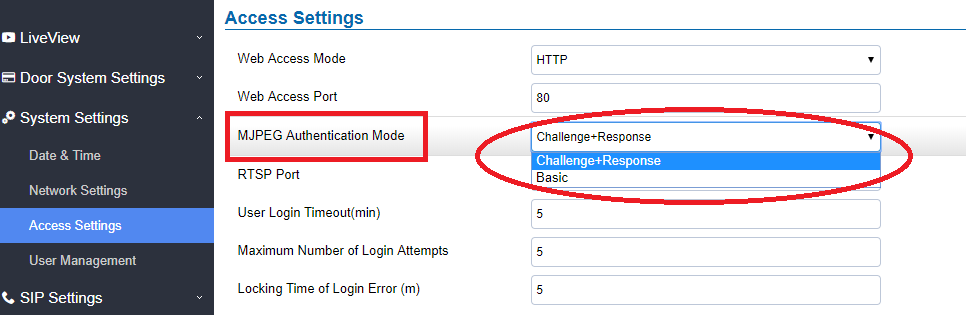
1). Challenge+Response MJPEG Authentication Mode:
In order to get a live view stream using MJPEG stream over HTTP command on this mode, please follow the below steps:
- In browser type in: http(s)://IP_Address_GDS:Port/jpeg/mjpeg.html
- The browser will pop up the window above asking for credentials, user needs to enter admin credential.
3. The browser will show MJPEG stream (720p).
2). Basic MJPEG Authentication Mode:
Please follow below steps in order to take a snapshot via HTTP commands:
- In browser type in: http(s)://admin:password@IP_Address_GDS:Port/jpeg/mjpeg.html
- The browser will show MJPEG stream (720p).

Where X=0,4,8 corresponded to 1st, 2nd and 3rd video stream (2nd recommended).
Door System Settings
Users can configure system operations parameters, like input PIN for the door and manage users’ settings.
Basic Settings
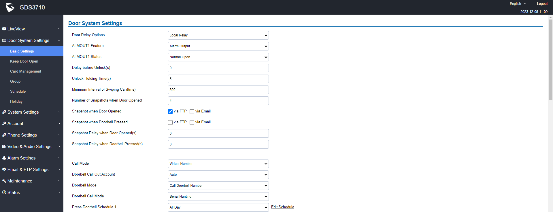
Door Relay Options | This feature allows customers to integrate GDS37XX with 3rd party web relay to control door open over network, via script or other applications, to meet real application scene and enhance security. User need to input web relay IP address or domain name, as well as authentication information, to make this to work. There are four choices in the pull-down selection:
Note: In web relay mode, the strike is wired to the web relay controller device. |
Webrelay URL ON | When Door relay Option set to Webrelay, then enter the correct URL used by the third party controller so that the GDS3710 send the command to activate the relay. This adds an extra layer of security so when legal open door event happened, the configured web relay will get the communication from GDS3710, and will operate the strike to open door for the authenticated open door request or use that command to operate other industry application. Notes:
|
Webrelay URL OFF | When Door relay Option set to Webrelay, then enter the correct URL used by the third party controller so that the GDS3710 send the command to disable the relay. |
Webrelay Username | Enter the web relay username. |
Webrelay Password | Enter the web relay password. |
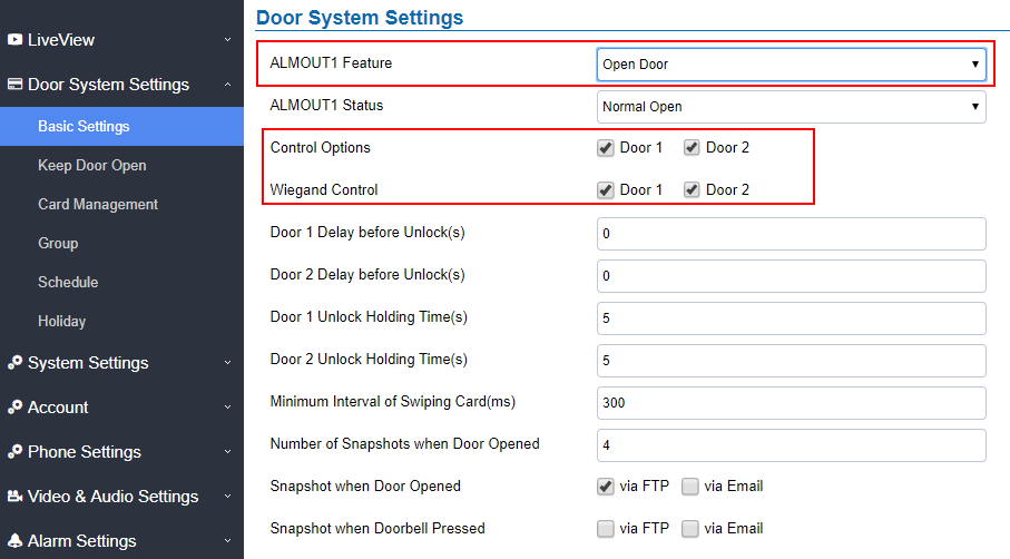
ALMOUT1 Feature | This option allows to choose to use Alarm_Out (COM1) interface for either as alarm out with 3rd party device, or to control a second door “Door 2” (the two functions are mutual exclusive). When the option “Open Door” is selected, will enable GDS3710 to control the operation of two doors via RFID, and local and remote PINs. |
ALMOUT1 Status | Select Normal Open or Normal Close depending on the lock used. |
Delay before Unlock (s) | Device will open door after specified delay (in seconds) when user issuing the authorization. |
Unlock Holding Time (s) | Configures the lock holding time, in seconds (default value is 5 seconds). Device will hold the door unlocked for this specified duration. Range: 1-1800 seconds. |
One-way Interlocking Doors Mode | This option allows to control two doors for access control in one-way mode. Once the card or PIN is fully validated by the GDS3710, it will check the status of both doors (using 3rd party window/door sensors - not provided by Grandstream - to verify if they are opened or closed), if |
Control Options | Configures weather to allow the two doors to be controlled by local RFID cards or PINs for access. |
Wiegand Control | Configures weather to allow the two doors to be controlled by wiegand or keypad Input. |
Door 1 Delay before Unlock(s) | The device will open door 1 after the specified delay (in seconds) when user has issues the authorization. |
Door 2 Delay before Unlock(s) | The device will open door 2 after the specified delay (in seconds) when user has issues the authorization. |
Door 1 Unlock Holding Time(s) | The device will hold the door 1 unlocked for a while (1-1800 seconds) |
Door 2 Unlock Holding Time(s) | The device will hold the door 2 unlocked for a while (1-1800 seconds) |
Minimum Interval of Swiping Card (ms) | Defines the interval in ms to swipe consecutive RFID cards. The range should be between 0ms and 2000ms. |
Number of Snapshots when Door Opened | Define number of snapshot to be sent by the GDS (via FTP or Email) Maximum up to 4 screenshots. |
Snapshot when Door Opened | User can choose to email the snapshot when door is opened without sending the snapshots via FTP to the FTP server. |
Snapshot when Doorbell Pressed | User can choose to email the snapshot when doorbell pressed without sending the snapshots via FTP to the FTP server. |
Snapshot Delay when Door Opened(s) | Configures the delay in seconds to the snapshots taken when Door Opened. Default value is 0, meaning there will be no delay for taking the snapshot when door opened. |
Snapshot Delay when Doorbell Pressed(s) | Configures the delay in seconds to the snapshots taken when Doorbell pressed. Default value is 0, meaning there will be no delay for taking the snapshot when door pressed. |
Call Mode | Chooses whether to make call to the SIP number or Virtual Number when dialing from the GDS3710 keypad. |
Doorbell Call Out Account | This option sets the account to be used to make call upon the doorbell trigger. If set to Auto, the GDS will use the first available account. |
Doorbell Mode | Configures the action to be taken when the doorbell is pressed, three options are available:
|
Door Bell Call Mode | Select the ring strategy for the Numbers Called when pressing the Door Bell button to be either Serial or Parallel:
|
Press Doorbell Schedule [1-4] | Select the schedule when pressing the doorbell will call the configured destination. Notes:
|
Number [1-4] Called When Door Bell Pressed | Configures SIP extension number (SIP Server mode), or IP address with port number (peering mode), to be called when the Door Bell is pressed:
|
Maximum Number of Dialed Digits | Configure the maximum digits allowed to dial in the keypad. Once the configured condition is satisfied, the device will send out the number to call automatically without pressing #. It is disabled if set to 0. |
No Key Input Timeout(s) | Defines the timeout (in seconds) for no key entry. If no key is pressed after the timeout, the digits will be sent out without pressing #. The default value is 4 seconds. The valid range is from 1 to 15. |
Press Doorbell Schedule | Configure a schedule for the Doorbell button, once configured, the doorbell with turn ON/OFF based on configured schedule. Default setting is “All Day”. |
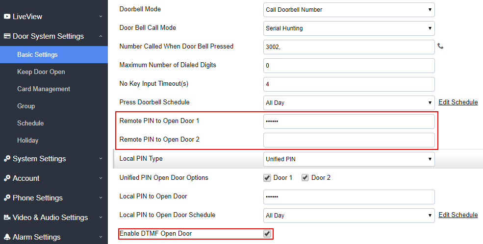
Remote PIN to Open the Door | Configures PIN code stored in the GDS3710, remote SIP phone needs to input and match this PIN (the PIN is sent via DTMF while in call) so that the GDS3710 can open the door. Note: For enhanced security, when the call is initiated from GDS then only the numbers existing in “White List” will be able to use DTMF PIN to open door remotely. |
Local PIN Type | Three options are available: Private Card PIN, Unified PIN or Card and Private PIN.
Notes:
Note: Door can still be opened by Card and with the sequence [*Virtual Number*Private PIN]. For more details and conditions, refer to [Disable Keypad SIP Number Dialing].
Notes: If “Disable Keypad SIP Number Dialing” is checked, users will be able to open door using Local PIN with following sequence [Local PIN].
Note : This feature is available to be configured only on the GDS3710 Model. |
Local PIN to Open the Door | Configures PIN stored in GDS3710, input locally this PIN on the GDS3710 keypad will unlock the door. This feature needs Private PIN, means every member has a private PIN, the GDS will record who unlocked the door every time. Users need to enter the following sequence from the GDS3710 to open the door [*Virtual Number*Private PIN#]. Note: When local PIN type is set to private card PIN, users can also open the door by swiping their cards. |
Local PIN to Open Door Schedule | Configure a schedule for the Local PIN to open the door. Once configured, the door opening ability using a local PIN with turn ON/OFF based on a configured schedule. The default setting is “All Day”. |
Enable DTMF Open Door | When enabled, remote SIP phones can open the door while in call by entering the remote PIN code configured (the PIN code is sent via DTMF). Default settings is disabled. |
Enable Guest PIN | Enables password entry for guests. |
Guest PIN | Configures the password that will be used by guests. |
Guest PIN Start Time | Selects the start time when the Guest PIN start to take effect. |
Guest PIN End Time | Selects the end time when the Guest PIN will stop working. |
Disable Auto Answer | If checked, GDS3710 will not answer incoming calls automatically, users can press any key to answer the call. Default setting in unchecked. |
Enable Doorbell Button to Hang up Call | If checked, Users can hang up an active call when pressing the doorbell button. Enabled by default. |
Disable Keypad (except the Doorbell Button) | When checked the Keypad will be disabled, only Door Bell button can be pressed. |
Enable On Hook After Remote Door Opened | When checked calls will be disconnected automatically after the remote open door event. |
Onhook Timer After Remote Open Door(s) | Defines the duration in seconds when the calls will be disconnected after the remote open door event. |
Enable HTTP API Remote Open Door | Enabling this option allows to use HTTP API command to open the door remotely.
1. Open the door command example: https://admin:password@192.168.23.123/goform/apicmd?remotepin=12345&type=1 2. Close the door command example: https://admin:password@192.168.23.123/goform/apicmd?remotepin=12345&type=2 Important note: We will not be responsible for any security problems resulting from opening the HTTP API remote function, this option is disabled by default and the user should enable it while knowing how to mitigate the risk. |
HTTP API Open Door Compatibility Mode | If this option is enabled, HTTP API Open Door will be supported under HTTPS mode. |
Disable Keypad SIP Number Dialing | When Keypad SIP number Dialing disabled, device will interpret each digit entry as private-password open door request after pressing #. Notes:
|
Enable Card Issuing Mode | Enables RFID card issuing/program into the GDS3710. When selected sweeping an RFID card into the GDS3710 will add card information into. |
Card issuing State Expire Time(m) | Card issuing mode will be automatically disabled when timer reached (The range of value is 1 – 1440, in minutes). |
Enable Key Blue Light | When checked, the blue light will be activated when pressing the GDS3710 Keys. |
Enable Background Light | When checked, the background light will turn on once clicking the GDS3710 Keys. |
Enable Doorbell Blue Light | When enabled, Doorbell LED will light based on the configured Start/End Time. For instance, this option can be used when GDS is deployed on dark environment, the GDS will be located easily using Doorbell LED. |
Enable Keypad Blue Light | When enabled, Keypad LED (except for Doorbell LED) will light based on the configured Start/End Time. For instance, this option can be used when GDS is deployed on dark environment, the GDS will be located easily using Keypad LED. |
Central Mode | If enabled, Group/Schedule/Holiday can only be synchronized from the Central (GDS Manager), local configuration will not be allowed. If disabled, only local configuration from GDS3710 is allowed. |
Key Sensitivity Level | Set the sensitivity level:
Notes: Most application scenes the Default setting of this firmware is good enough for application. Please use Default setting unless the usage scene really needs high keypad lever sensitivity. If with default or low sensitivity keypad, the false-positive ghost call issue still happens frequently, which might indicate inappropriate wiring or installation, or maybe the hardware is faulty. Please contact Our Grandstream Support for assistance to resolve such a problem. |
Key Tone Type | Configures the key tones for the GDS3710.
|
Enable Wiegand Input | This option needs to be enabled when GDS is connected to the wiegand. output device (RFID card reader for example) |
Wiegand Output | This option is to be enabled when the GDS is the wiegand output device. (example: input device is a door controller) |
Notes: Remote SIP phone needs password (digits 0-9 only, ended with # key) matching the configuration on the web page to open the door (via DTMF).
GDS3710 support RFID for multiple users to open door, therefore every user has its own PIN. For environment with large number of users (limit is 2000), it’s difficult for the GDS3710 to manage all these users, so a separate PC or Server should be involved for such kind of management and monitoring.
In environments with large number of users (limit is 2000), the GDS3710, another possibility would be to set one unified Local PIN for opening the door for all the users.
Using Alarm Out (COM 1) to Control a Second Door
Starting from firmware 1.0.5.2, user can now set Alarm_Out (COM1) interface to control a second Door, in additional to the existing Locker/COM2 interface (controlling Door1).
This feature allows GDS3710 to control the operation of two doors via RFID, local and remote PINs.
For example, a 3rd party Wiegand Input device or GDS3710 can be installed at Door2 with related cable wired into the control GDS3710 installed at Door1. The Door1 and Door2 can be configured to be open by programmed RFID cards, PINs either separately or both.
- Interface for Door Control (which Door can be OPEN):
If Alarm_Out (COM1) interface is set to control Door 2 opening, “ALMOUT1 Status” can be configured by choosing “Normal Open” or “Normal Close” based on the strike used.
Unlike default COM2 which is designed for strike control and having three connecting sockets, the COM1 only has two connecting sockets. Therefore correct lock mode has to be configured to make the strike working as expected.
For above example, the GDS3710 is configured to control Door1 (wiring to COM2 interface); the 3rd party Wiegand Input is set to control Door2 (wiring to COM1 interface).
In case of a power loss then the DOOR STATUS when power is off will be depending on the following situations:
- COM2 has three wiring PINs, corresponding to NO or NC accordingly. Therefor when connecting NC2 and COM2 (Fail Safe) then strike will open when power is lost and when using a NO2 strike (connecting COM2 and NO2) then door is “locked” when power is lost (Fail Secure).
- COM1 (ALMOUT1) has only two PIN, and NO ONLY. If the connected strike/lock is a NO strike, this means ALMOUT1 Status should be set to “Normal Open” then door will be closed when power is lost, while if the strike connected is NC strike, and ALMOUT1 Status is set to “Normal Close” then door will be open when power is lost.
- Universal PIN for Operation of Doors:

If Unified PIN (Universal PIN) is configured to open door, then which door can be controlled by the PIN is configured in the UI once “Unified PIN” selected.
For example, like above screenshot, if this universal PIN is set to open both Door1 and Door2, but due to previous “Control Option” set to open Door1, and “Wiegand Control” set to open Door2, therefore the final result will be the INTERSECT result of both sets with condition qualified.
- Remote PIN to Operation of Doors:
For remote PIN to open door, the PIN can be configured in example down below.
The PIN can be different for Door1 and Door2 and has to be configured correctly in related IP Phone which will be used to operate “One Key Open Door”.
If BOTH doors need to be opened at the same time, then both Door1 and Door2 has to be configured with exactly SAME password or PIN as DTMF open door.
- Private PIN or Card & Private PIN:
If using RFID card or Private PIN to open door, then which door can be opened by the RFID card or Private PIN is configured via “Card Management”, see above screenshot.
Please refer to our Open Door Flow chart for better understanding on how to configure and control 2 Doors operation: http://firmware.grandstream.com/GDS3710_opendoors_logic.pdf
Keep Door Open
This feature allows users to set either an immediate or scheduled open door, this will allow usage scene like schools or similar private or public places where the door needs to keep open at specific time window and closed otherwise. Also handy for buildings or properties where a seminar needs to be hosted for some period or lunch breaks in a factory or company where the door keeps open and no access log required then back to locked with authorized entry after that, by default it’s disabled.
The GDS3712 gives the option to configure Door1 and Door2 separately with either Immediate door open or Scheduled door open unlike the GDS3710 which has one configuration for both doors.
There are two modes under this section:
- Immediate Open Door (One Time Only Action)
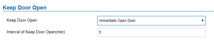
Keep Door Open | Select the Keep Door Open mode. |
Length(m) to Keep Door Open | Set the amount of time in minutes where the door will keep opened. Click Default is 5 minutes. |
2. Schedule Open Door (Repeated Action)
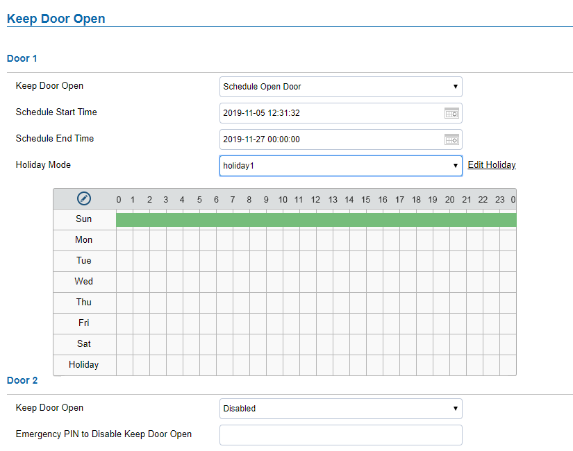
Select the Keep Door Open mode (Schedule Open Door on this case). | |
Schedule Start Time | Selects the start time when the door will be opened. |
Schedule End Time | Selects the end time when the door will be locked. |
| Schedule | Selects the preconfigured schedule from the list of schedules. |
Selects the holiday schedule to be included into the Keep Door Open schedule (Supported for Door 1 and Door 2). |
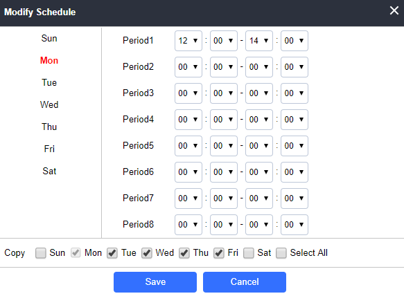
Click on Edit schedule to select which periods for each day the door will remain open, as shown on below screenshot.
Emergency PIN
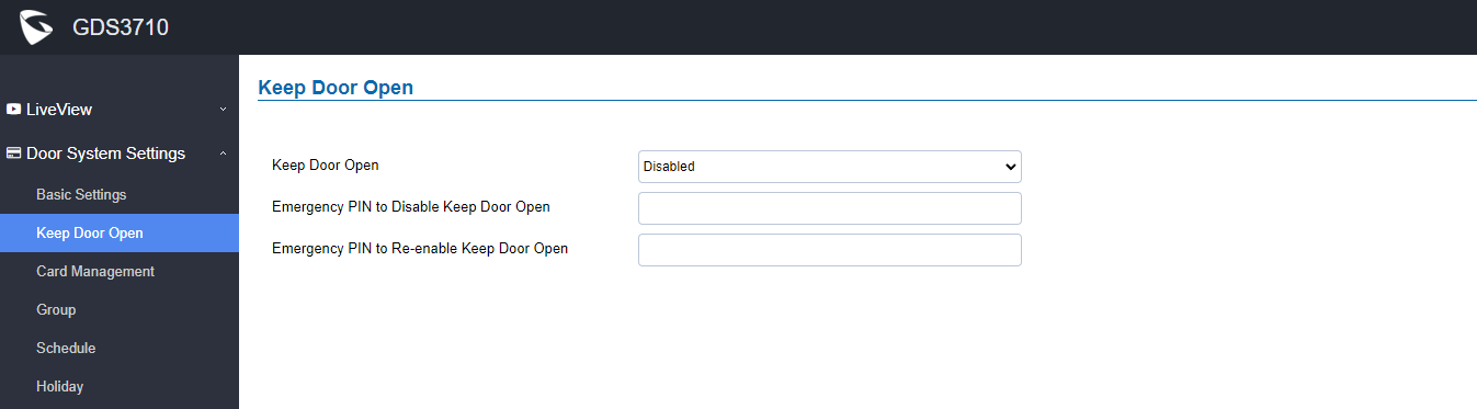
When Keep Door Open option is set to “Disabled”, user is offered the possibility to force closing the door from the device keypad by dialing the Emergency PIN set to be used.
Example:
- Fill in the password in Emergency PIN to Disable Keep Door Open, in our example: 2018
- Open the door using either Immediate/Scheduled Keep Door open
- enter the following Emergency Password sequence: *2018#
- After entering the sequence *Emergency PIN to disable#, the GDS will close the door, and when entering the web GUI, the Keep Door Open section is switched automatically to “Disabled” Option.
- Incase the user wants to re-enable the keep door open option, he can enter the sequence *Emergency PIN to re-enable#, in our example it will be *2019#, the GDS will re-enable the open door when the PIN is provided.
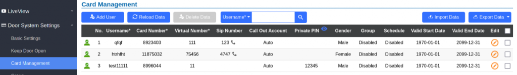
Card Management
This page allows users to add information about RFID cards, two options are possible either add RFID cards manually or automatically.

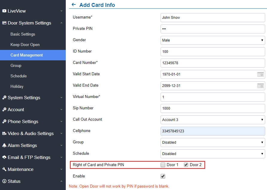
Add Users Manually
To add users, click on ![]() , the following page will pop up.
, the following page will pop up.
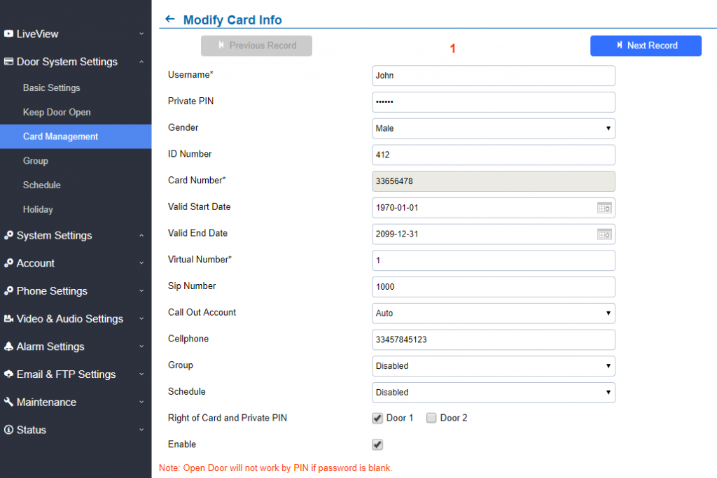
Username | Configures the username to identify the user. |
Specifies a PIN to unlock the door for this particular user. | |
Gender | Selects a gender, either Male or Female. |
ID Number | Enters an ID number (This number is set by the admin to identify each user uniquely). |
Enters the RFID Card number (this is the number written on the RFID card. When “card issuing mode” is enabled, this field will be added automatically. Maximum number that can be entered is 2147483647. | |
Valid Start Date | Configures the start date of validity of the RFID card. |
Valid End Date | Configures the End date of validity of the RFID card. |
When dialing directly from the keypad, the GDS accept only Virtual number to identify a user, once the Virtual number is typed followed by # key, the SIP Number will be dialed. | |
Configures the SIP Number which is mapped with virtual number. Once the virtual number is dialed the GDS3710 will send an INVITE to the SIP Number. Note: The SIP Number can be configured with an extension/phone number or IP address. Example: 192.168.5.124 | |
Call Out Account | Select the Account from which the GDS3710 will call the User SIP Number when dialing from the keypad. Default is Auto. |
Cellphone | Configures cellphone of the user. |
Group | Specifies to which group the user will be added. |
Schedule | Specifies the schedule that will be assigned to the user. |
Right of Card and Private PIN | Select the doors that can be accessed by user. |
Enable | When checked, the user’s RFID and Private PIN will be active for door opening. If unchecked, the Private PIN nor RFID card swipe won’t take effect. |
Add Users Automatically
If [Enable Card Issuing Mode] is checked, the GDS3710 keypad will start blinking and once an RFID card is swiped, data stored on the card will be added into the GDS3710 card management page, user can still edit the entry added automatically by modifying some fields.
Users Operation
-
Click on
 to edit the entry or show details of the entry.
-
Select the entries and click on
 to delete the selected users.
-
Click
 to refresh the data entered to the GDS3710.
-
Users can use
 to navigate through User Management pages.
Show private PIN
The private PIN can be displayed easily from the card management page using the eye icon.

To enable this feature, on the web UI, head to System Settings > Access Settings, switch the Web Access Mode to HTTPS and enable PIN/Password Display (HTTPS)
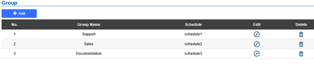
Group
The Group page permits to manage the groups which will contains multiple users, click on
![]() to create new groups or
to create new groups or
![]() to edit existing groups or
to edit existing groups or
![]() to delete the group.
to delete the group.
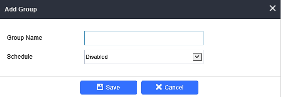
Group Name | Configures the name to identify the group. |
Schedule | Specifies the schedule that will be used by the group. |
The following screenshots display the list of the created groups.
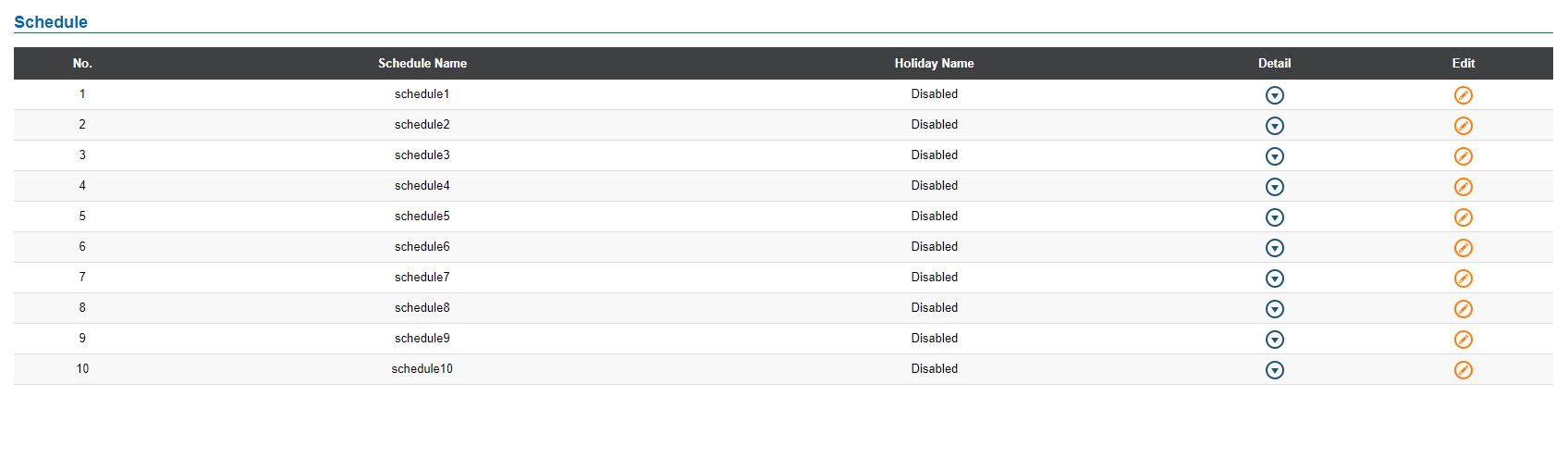
Schedule
The Schedule page allows to manage schedule time frames which will be assigned to the users for door system usage. Out of the configured time intervals, GDS3710 will not allow users to access.
Click on ![]() to edit a schedule or
to edit a schedule or ![]() for schedule details.
for schedule details.
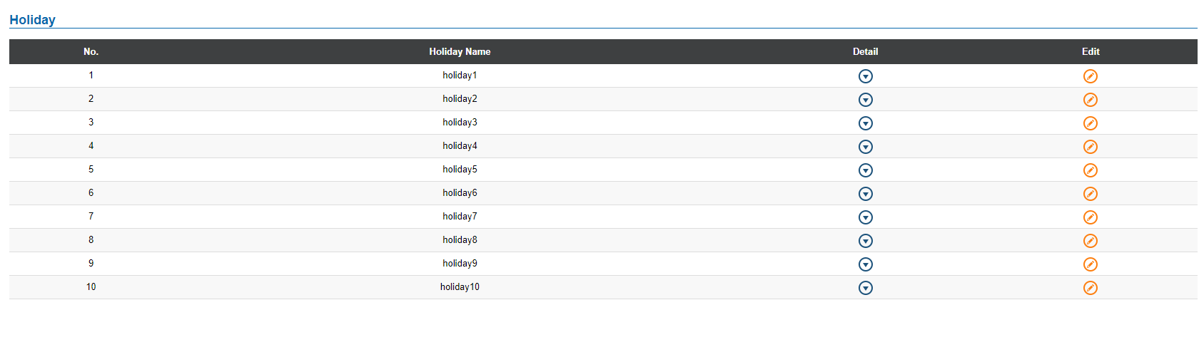
Holiday
The Holiday page allows to manage holidays which will be assigned to the users for door system usage.
Click on ![]() to edit the holidays or
to edit the holidays or ![]() for holiday details.
for holiday details.
System Settings
This page allows users to configure date and time, network settings as well as access method to the GDS3710 and password for accessing the Web GUI.
Date & Time Settings
This page allows users to adjust system date and time of the GDS371x.
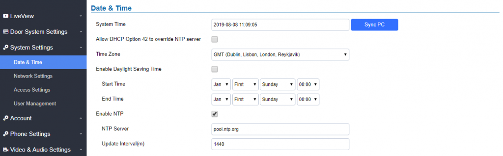
System Time | Displays the current system time. |
Defines whether DHCP Option 42 should override NTP server or not. When enabled, DHCP Option 42 will override the NTP server if it’s set up on the LAN. The default setting is “Yes”. | |
Sync PC | Clicks to synchronize current time with the computer. |
Selects from drop down menu the preferred time zone. | |
Enable Daylight Saving Time | Enables Daylight Saving Time. |
Start time | Selects the Start time of DST. |
End Time | Selects DST end time. |
Enable NTP | Enables NTP to synchronize device time. |
NTP Server | Configures the domain name of NTP server. |
Update Interval | Configures the Interval (in minutes) to retrieve updates from the NTP server. |
Network Settings
This page allows users to set either a static or DHCP IP address to access the GDS3710.

IP Address Mode | Selects DHCP or Static IP. Default DHCP. (Static recommended) |
IP Address | Configures the Static IP of the GDS3710. |
Subnet Mask | Configures the Associated Subnet Mask. |
Gateway | Configures the Gateway IP address. |
DNS Address Type | Specifies the DNS type used: Dynamic DNS or Static DNS. |
DNS Server 1 | Configures DNS Server 1 IP address. |
DNS Server 2 | Configures DNS Server 2 IP address. |
Controls the LLDP (Link Layer Discovery Protocol) service. The default setting is “Enabled”. | |
Assigns the VLAN Tag of the Layer 2 QoS packets. Default value is 0. | |
Layer 2 QoS 802.1p Priority Value | Assigns the priority value of the Layer2 QoS packets. Default value is 0. |
OpenVPN® Settings
This page allows users to configure OpenVPN settings.
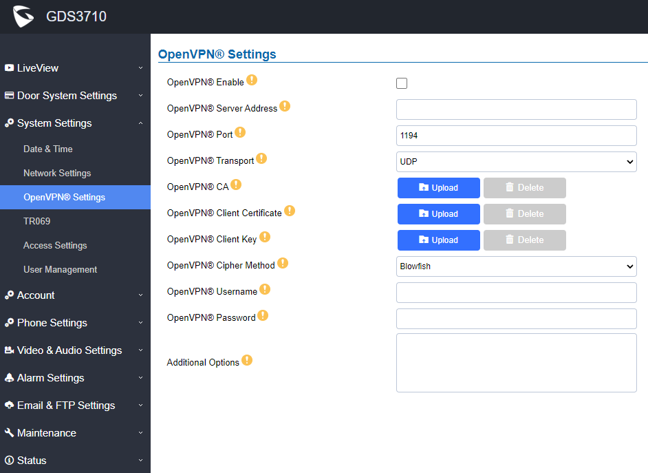
Enable OpenVPN® | Enables/disables OpenVPN® functionality and requires the user to have access to an OpenVPN® server. Note: To use OpenVPN® functionalities, users must enable OpenVPN® and configure all of the settings related to OpenVPN®, including server address, port, OpenVPN® CA, certificate and key. Additionally, the user must also set the SIP account to use “VPN” for the “NAT Traversal” (under Account 🡪 Network Settings). |
OpenVPN® Server Address | Defines the URL/IP address for the OpenVPN® server. |
OpenVPN® Port | Defines the network port for the OpenVPN® server. The default setting is 1194. |
OpenVPN® Transport | Determines network protocol used for OpenVPN® (UDP or TCP). The default setting is TCP. |
OpenVPN® CA | OpenVPN® CA file (ca.crt) required by the OpenVPN® server for authentication purposes. Press “Upload” to upload the corresponding file to the device. |
OpenVPN® Client Certificate | OpenVPN® CA file (ca.crt) required by the OpenVPN® server for authentication purposes. Press “Upload” to upload the corresponding file to the device. |
OpenVPN® Client Key | OpenVPN® Client key (*.key) required by OpenVPN® server for authentication purposes. Press “Upload” to upload the corresponding file to the device. |
OpenVPN® Cipher Method | The cipher method of OpenVPN®, must be the same cipher method used by the OpenVPN® server. Supported methods are: Blowfish, AES-128, AES-256 and Triple-DES. |
OpenVPN® Username | Configures the OpenVPN® authentication username (optional). |
OpenVPN® Password | Configures the OpenVPN® authentication password (optional). |
Additional Options | Additional options to be appended to the OpenVPN® config file, separated by semicolons. For example, comp-lzo no; auth SHA256 Note: Please use this option with caution. Make sure that the options are recognizable by OpenVPN® and do not unnecessarily override the other configurations above. |
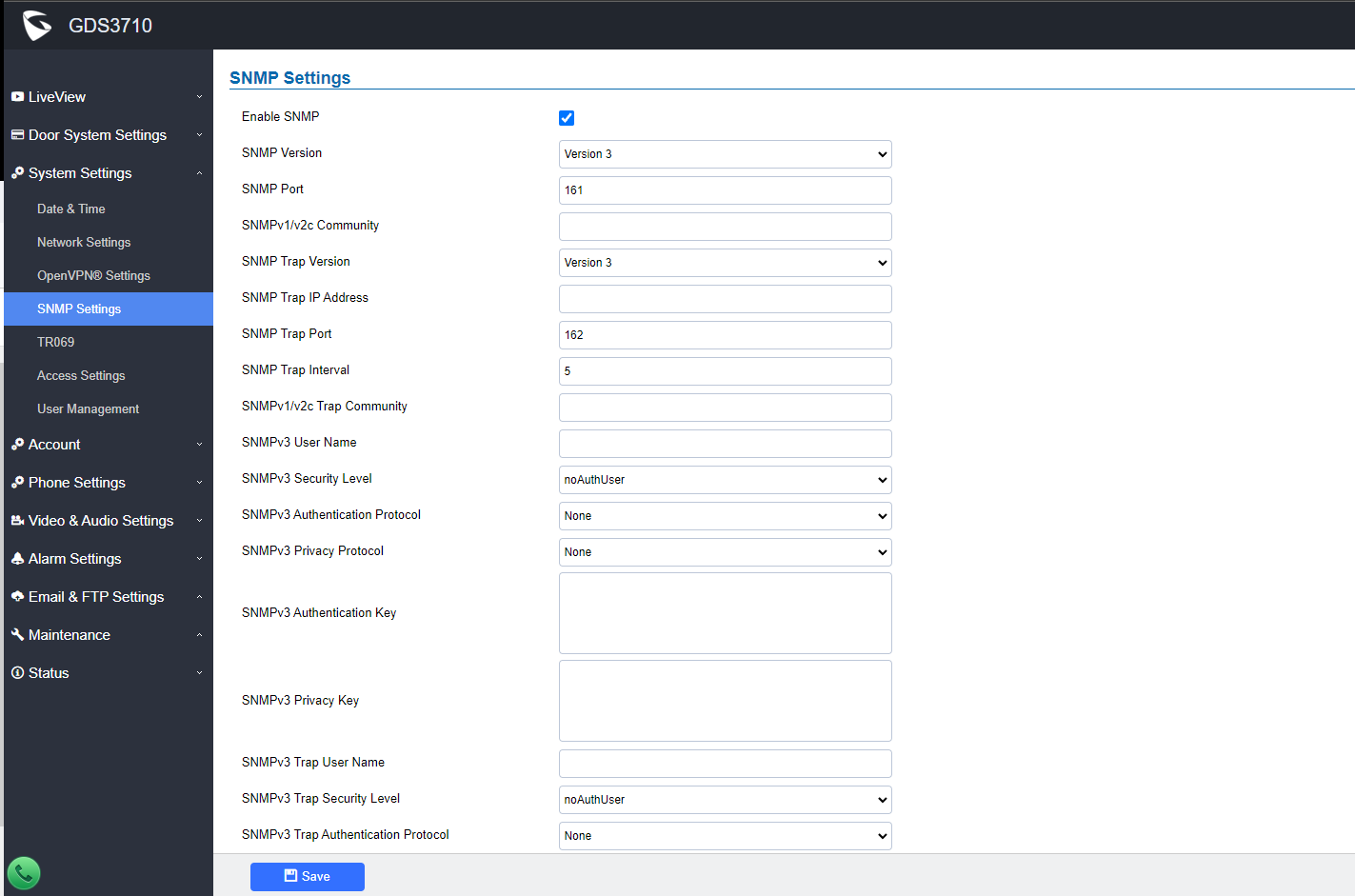
SNMP Settings
This page configures the GDS371x SNMP parameters.
Field | Description |
Enable SNMP | Enable/Disable SNMP feature. The default setting is "disabled". |
Version | Select the SNMP version.
The default setting is "Version 3" |
SNMP Port | Defines the SNMP port. The default setting is "161". |
SNMPv1/v2c Community | Enter the SNMPv1/v2c Community. |
SNMP Trap Version | Select the SNMP Trap Version.
The default setting is "Version 3" |
SNMP Trap IP Address | Enter the SNMP Trap IP Address. |
SNMP Trap Port | Enter the SNMP Trap Port. The default setting is "162".
|
SNMP Trap Inverval | Set the SNMP Trap Interval. The default setting is "5". |
SNMPv1/v2c Trap Community | Enter the SNMPv1/v2c Trap Community. |
SNMPv3 Username | Enter the SNMPv3 Username. |
SNMPv3 Security Level | Select the SNMPv3 Security Level.
The default setting is "noAuthUser". |
SNMPv3 Authentication Protocol | Select the SNMPv3 Authentication Protocol.
The default setting is "None". |
SNMPv3 Privacy Protocol | Select the SNMPv3 Privacy Protocol.
|
SNMPv3 Authentication Key | Enter the SNMPv3 Authentication Key. |
SNMPv3 Privacy Key | Enter the SNMPv3 Privacy Key. |
SNMPv3 Trap User Name | Enter the SNMPv3 Trap User Name |
SNMPv3 Trap Security Level | Select the SNMPv3 Trap Security Level.
The default setting is "noAuthUser". |
SNMPv3 Trap Authentication Protocol | Select the SNMPv3 Trap Authentication Protocol.
The default setting is "None" |
SNMPv3 Trap Privacy Protocol | Select the SNMPv3 Trap Privacy Protocol.
The default setting is "None". |
SNMPv3 Trap Authentication Key | Enter the SNMPv3 Trap Authentication Key. |
SNMPv3 Trap Privacy Key | Enter the SNMPv3 Trap Privacy Key. |
TR-069
This page configures the GDS371x TR-069 parameters.
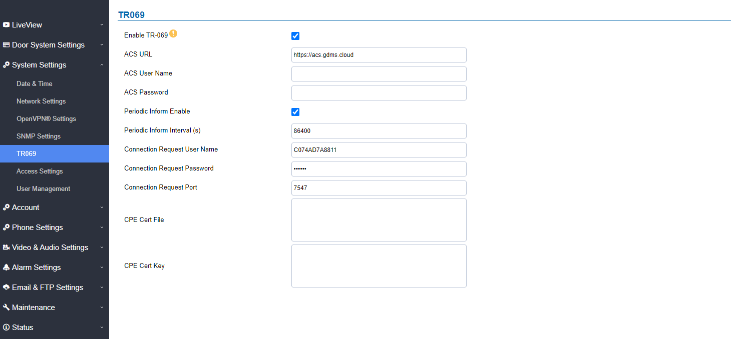
Enable TR-069 | Sets the device to enable the “CPE WAN Management Protocol” (TR-069). The default setting is “No”. Note: Reboot the device to make changes take effect. |
ACS URL | Specifies URL of TR-069 ACS (e.g, http://acs.test.com), or IP address. |
ACS Username | Enters username to authenticate to ACS. |
ACS Password | Enters password to authenticate to ACS. |
Periodic Inform Enable | Sends periodic inform packets to ACS. The default is “No”. |
Periodic Inform Interval (s) | Configures to send periodic “Inform” packets to ACS based on a specified interval. The default setting is 86400. |
Connection Request Username | Enters username for the ACS to connect to the device. |
Connection Request Password | Enters the password for the ACS to connect to the device. |
Connection Request Port | Enters the port for the ACS to connect to the device. |
CPE Cert File | Enters Cert File for the device to connect to the ACS via SSL. |
CPE Cert Key | Uploads Cert Key for the device to connect to the ACS via SSL. |
TR-069 settings
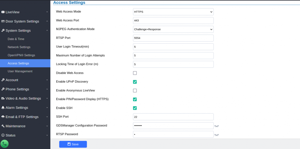
Access Settings
This page configures the GDS371x access control parameters.
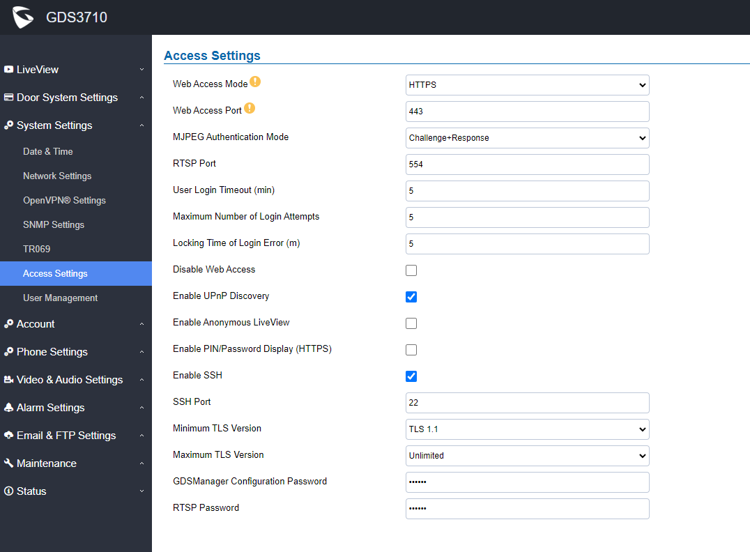
Web Access Mode | Selects the access mode to the webGUI either HTTP or HTTPS. |
Web Access Port | Specifies the TCP port for Web Access, default 443. |
JPEG Authentication Mode | Allows 3rd party system integrator or developers to implement related application for users. By default, this feature is disabled and use more secured “Challenge+Response” mode. If enabled, user can send HTTP API with correct credentials to retrieve MJPEG video stream or JPEG snapshot from GDS3710. Notes: 1. The MJPEG stream can be retrieved via the following URL HTML based 🡺 http(s)://admin:password@IP_GDS3710:Port/jpeg/mjpeg.html Stream 🡺 http(s)://admin:password@ip:port/jpeg/stream
The MJPEG stream retrieved via the methods above is running on the background and cannot be tuned. If users want more flexibility, they can use the three configurable video streams as shown on [Retrieving Video Streams]. |
RTSP Port | Specifies RTSP port for media stream, default TCP port 554. |
User Login Timeout(min) | If no action is made within this time the GDS371x will logout from the Web GUI, range is between 3 and 60. |
Maximum Number of Login Attempts | Specifies the allowed login times error limit, if the unsuccessful login attempts exceed this value, the GDS371x webGUI will be locked for the time specified in Login Error Lock Time. |
Locking Time of Login Error (m) | Specifies how long the GDS371x is locked before a new login attempt is allowed. |
Disable Web Access | Allow or deny the web access to the GDS371x. (HTTP API do not take effect when this option is enabled).
Note: If both WebUI and SSH are disabled, GDS371x will get blocked and not be able to be accessed. Only two ways to get it back:
1. Re-provisioned by ITSP or Service Provider (by adjusting the related parameters) 2. Hard Reset (GDS371x has to be offline and uninstalled to perform this hard reset). |
Enable UPnP Discovery | UPnP (or mDNS) function for local discovery. Default setting is enabled. |
Enable Anonymous LiveView | 1. When enabled, user can display the camera stream from GDS without admin credentials using the following URL scheme: http(s)://GDS371x_IP:port/videoview.html 2. User can also retrieve a real-time snapshot without admin credentials using the following URL: http(s)://IP:port/anonymous/snapshot/view.html Or with: https://IP_GDS371x:Port/anonymous/snapshot/view.jpg 3. To retrieve video stream via RTSP, users can use the following format: rtsp://IP _GDS371x:Port/X where X=0,4,8 for 1st, 2nd, 3rd streams respectively. 4. To retrieve Anonymous MJPEG, user can use following URLs to retrieve the related MJPEG streams: http(s)://IP:Port/anonymous/jpeg/stream=X (X=0, 1, 2, or default 3) For example: https://192.168.1.128/anonymous/jpeg/stream=3 Notes: Except default value 3, the stream 0, 1, 2 mapped to the stream 1, 2, 3 in the “Video Setting” page. Unless using default value 3, all other values require to choose “MJPEG” in the “Preferred Video Codec” in the “Preferred Video Codec” |
Enable SSH | Allows SSH access for remote secured configuration purposes (restart, upgrade, provision…) |
Enable PIN/Password Display (HTTPS) | If Enabled, this option allows to view system PIN/Password. Default setting is Disabled. |
SSH Port | Specifies the SSH port. Default setting is 22. |
Minimum TLS Version | Configures the minimum TLS version supported by the device. |
Maximum TLS Version | Configures the maximum TLS version supported by the device. |
GDSManager Configuration Password | User can set in this field a custom admin password instead of using GDS371x webUI administrator’s credentials, and this custom admin password will be the one used when adding the GDS371x unit to GDSManager database.
Default password is the Admin’s default random password of the GDS371x. |
RTSP Password | This feature enhancement is based on field feedback from customers. Customer request NOT using admin password to view the RTSP video stream via 3rdparty applications like VLC Player or own development Scripts. Now customer can still use admin as username, but NOT use admin password and configure another RTSP password to view the live stream via own scripts or 3rd party application like VLC Media Player. For example, using VLC Media Player, if configure the RTSP password to be “1234” in GDS371x, then using following command can get the video stream: rtsp://admin:1234@192.168.11.128/4 (here it shows the 2ndstream as “4” used) FORMAT: RTSP://admin:rtsp_password@IP_GDS371x:Port/X (X = 0, 4, 8 correspondent to Stream 1, 2, 3) The selected live video stream with audio will play out with some delay based on the computer processing power and network conditions. Notes: Please make sure the environment is secure before using this feature. Please reminder user the privacy when using this feature.
|
User Management
This page allows users to configure the password for administrator. Since this is a door system which must be a secure product, the use is only limited to administrator.
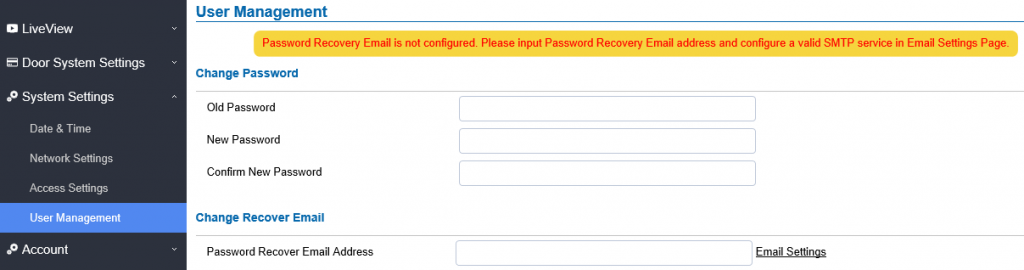
Old Password | Old password must be entered to change new password. |
New Password | Fill in the revised new password in this field. |
Confirm User Password | Re-enter the new password for verification, must match. |
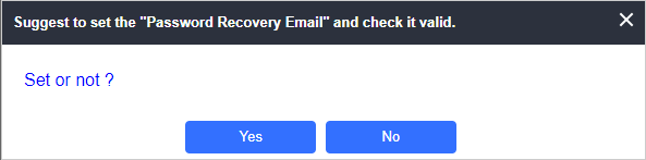
Password Recovery Email Address | This option is highly recommended, as if the password is lost, you can recover it on the configured Email address. Note: Make sure to configure SMTP Email Settings under “Email Settings” |
Account
Starting from version 1.0.5.6, the GDS371x supports four SIP accounts and four lines, this section covers the configuration of basic and advanced sip settings for each account.
Account 1 – 4
This page allows the administrator to configure the SIP account basic and advanced settings for each SIP account:
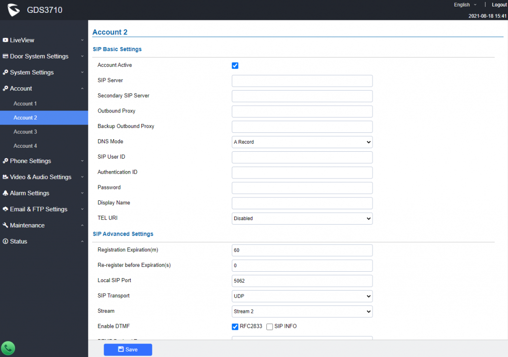
SIP Basic Settings | |
Account Active | This field indicates whether the account is active. Default setting is “Yes”. |
SIP Server | Configures the FQDN or IP of the SIP server from VoIP service provider or local IPPBX. |
Secondary SIP Server | Configures the FQDN or IP of the secondary SIP server from the VoIP service provider or local IPPBX. |
Outbound Proxy | Configures the IP address or the domain name of the outbound proxy, media gateway, or session border controller. It’s used by the GDS for firewall or NAT penetration in different network environments. If a symmetric NAT is detected, STUN will not work and only an outbound proxy can provide a solution. |
Backup Outbound Proxy | Configures the backup outbound proxy to be used when the “Outbound Proxy” registration fails. By default, this field is left empty. |
DNS Mode | Configure which DNS mode will be used to translate the SIP Server FQDN (Default value is A Record):
|
SIP User ID | Configures the SIP username or telephone number from ITSP. |
Authenticate ID | Configures the Authenticate ID used by SIP proxy. |
Password | Sets the Authenticate password used by SIP proxy. |
Display Name | To allow user to input display name to be illustrated in far side SIP device(if having LCD display or similar hardware) so user will know what extension or device connected in SIP calling, to increase the usability. |
TEL URI | Select “User=Phone” or “Enabled” from the dropdown list. |
SIP Advanced Settings | |
Registration Expiration (m) | Sets the registration expiration time. |
Re-register before Expiration (s) | Specifies the time-frequency (in seconds) that the GDS371x sends a re-registration request before the Register Expiration. The default value is 0. The range is from 0-64800 seconds. |
Local SIP Port | Sets the local SIP port. Default setting is 5060 for Account 1, 5062 for Account 2, 5064 for Account 3, 5066 for Account 4. |
SIP Transport | Chooses the SIP transport protocol. UDP, TCP or TCP/TLS. |
Check Domain Certificates | When using SIP with TLS/TCP, the "Check Domain Certificates" parameter plays a role in determining whether the GDS371x device should verify the presented domain certificates for security purposes.
|
Stream | Select the Video stream to be used by the GDS371x when a call is made from this SIP Account. |
Enable DTMF | Specifies the mechanism to transmit DTMF digits. There are 2 supported modes: |
DTMF Payload Type | Configures the payload type for DTMF using RFC2833. |
Unregister On Reboot | Allows the SIP user’s registration information to be cleared when the GDS reboots. The SIP REGISTER message will contain “Expires: 0” to unbind the connection. |
NAT Traversal | This parameter configures whether the NAT traversal mechanism is activated. Users could select the mechanism from No, STUN, Keep-alive,UPnP, Auto. The default setting is “No”. |
Enable SRTP | Enable SRTP mode based on your selection from the drop-down menu. |
Special Feature | Configures GDS settings to meet different vendors’ server requirements. |
Outbound Proxy Mode | In route: outbound proxy FQDN is placed in the routeing header. This is used for the SIP Extension to notify the SIP server that the device is behind a NAT/Firewall. |
Enable RTCP | This option allows 3rd party Service Providers or Cloud Solutions to monitor the operation status of the GDS371x by using related SIP Calls. |
H.264 Payload Type | The H.264 payload type can now be configured to be compatible with 3rd party video phones, as well as other advanced SIP settings, to easy the system integration process. The default is 99. |
Accept Incoming SIP from Proxy Only | When set to “Yes”, the SIP address of the Request URL in the incoming SIP message will be checked. If it doesn’t match the SIP server address of the account, the call will be rejected. The default setting is disabled. |
Add MAC in User-Agent | This option is used with 3CX so that the GDS37xx can be compatible with 3CX auto-provisioning. The option adds the MAC address into User-Agent in the SIP Header. |
SIP URI Scheme When Using TLS | This option allows the GDS371x to work with the Cisco WebEX server as a SIP client. The two modes are SIP and SIPS. |
Support SIP Instance ID | When enabled, the GDS371x will work with the Cisco WebEx server as a SIP client. |
Vocoder Settings | |
Preferred Vocoder 1 | Selects the first audio codec by priority order (lowest is the highest priority). Supported codecs are PCMU, PCMA, G.722, and G.729A/B. |
Preferred Vocoder 2 | Selects the second audio codec by priority order (lowest is the highest priority). Supported codecs are PCMU, PCMA, G.722, and G.729A/B. |
Preferred Vocoder 3 | Selects the third audio codec by priority order (lowest is the highest priority). Supported codecs are PCMU, PCMA, G.722, and G.729A/B. |
Preferred Vocoder 4 | Selects the fourth audio codec by priority order (lowest is the highest priority). Supported codecs are PCMU, PCMA, G.722, and G.729A/B. |
Codec Negotiation Priority | Selects the negotiation Priority, wether it is for the Caller or the Callee, Set to Callee by Default. |
Voice Frame Per TX | Configures the number of voice frames transmitted per packet. When configuring this, it should be noted that the “ptime” value for the SDP will change with different configurations here. This value is related to the codec used and the actual frames transmitted during the in-payload call. For end users, it is recommended to use the default setting, as incorrect settings may influence the audio quality. |
Phone Settings
The phone settings allow users to configure the GDS371x phone settings and the White list for all the SIP accounts.
Phone Settings
This page allows users to configure the GDS371x phone settings.
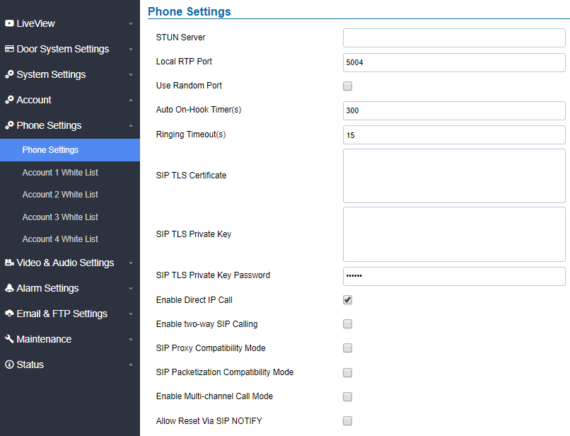
STUN Server | Configures the STUN server FQDN or IP. If the device is behind a non-symmetric router, STUN server can help to penetrate & resolve NAT issues. |
Local RTP Port | Sets the local RTP port for media. Default setting is 5004. Range between 1024~65400. |
Use Random Port | Forces the GDS to use random ports for both SIP and RTP messages. This is usually necessary when multiple units are behind the same full cone NAT. The default setting is “Disabled” Note: This parameter must be set to “Disabled” for Direct IP Calling to work. |
Auto On-Hook Timer | Configures the auto on-hook timer (in seconds) for automatic disconnecting the SIP call. Default setting is 300. Range between 0~65535. |
Ring Timeout(s) | Specifies the Ring timeout, when no reply is returned from the called party after exceeding this field, the GDS will hang up the call. The value is in the range of 0s – 90s. By default; it is “30” seconds. |
DNS Cache Expiration Time(m) | Configures the DNS Cache expiration Time, the default value is 30 , the range is 1-1440 |
DNS Cache Duration(m) | Configures the DNS Cache expiration Duration, the default value is 30 , the range is 1-1440 |
SIP TLS Certificate | Input the TLS certificate here for encryption. |
SIP TLS Private Key | Input private key here for TLS security protection. |
SIP TLS Private Key Password | Specifies the password for SIP TLS private Key. |
Enable Direct IP Call | Accepts peer-to-peer IP call (over UDP only) without SIP server. Default is “Enabled”. |
Enable two-way SIP Calling | Allows the user to enable/disable the alarm sound during a SIP call triggered by doorbell pressing. |
SIP Proxy Compatibility Mode | Enables more proxy compatibility with cost of bandwidth, the SIP call will send audio no matter what. |
SIP Packetization Compatibility Mode | When enabled, the GDS will have in SDP “packetization-mode = 0”. This is required when GDS is interacting with legacy video phones that only accepts this value to decode the RTP. |
Enable Multi-channel Call Mode | This feature allows the device to receive multiple calls at the same time,
with one active and others on hold (up to 4 calls maximum). The first call
the blue LED light will light up keypad digit “1”, 2nd call will light up keypad
digit “2”, and so on. On hold call will have related digit blinking while active
call will have the digit blue LED solid light up. Call can be switched by
pressing the blinking digits. |
Allow Reset Via SIP NOTIFY | Allows to factory reset the devices directly through SIP Notify.
If “Allow Reset Via SIP NOTIFY” is “check”, then once the GDS3710 receives the SIP NOTIFY from the SIP server with Event: reset, the GDS3710 will perform a factory reset after authentication.
This authentication can be either with:
The admin password if no SIP account is configured on the GDS3710. The SIP User ID and Password credentials of the SIP account if configured on the GDS371x.
Default is unchecked (disabled). |
Phone Settings
Account [1-4] White List
This page allows users to configure the white list per account, which is a phone number or extension list that can call the GDS371x. (The call will be automatically answered when calling from a phone set on the white list, and all other inbound calls will be blocked), the user can configure up to 200 white phone numbers per SIP account.
Moreover, besides numbers associated to active cards, and numbers on the “Number Called When Door Bell Pressed” setting, all whitelisted numbers can open door remotely by using the respective PIN code.
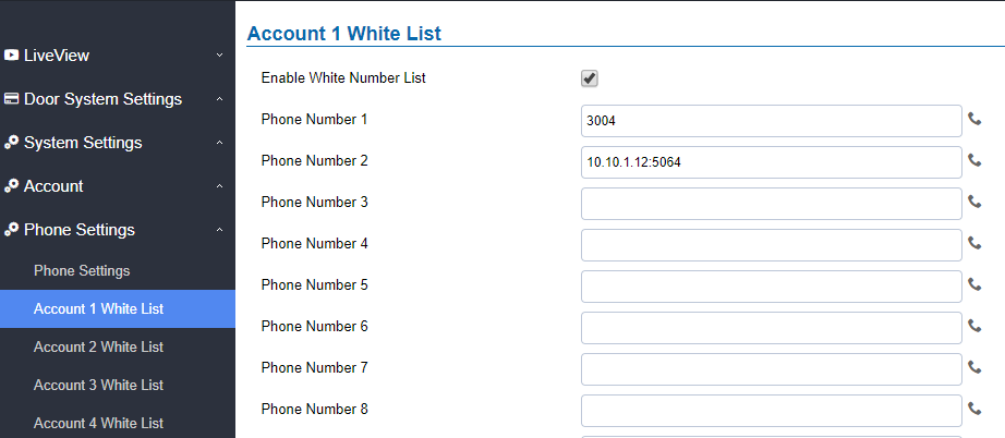
The table below gives a brief overview of the options:
Enable White Number List | Enables the White List feature. |
Phone Number 1 -200 | Adds a new phone number to the white list. |
Click-To-Dial
The GDS371x allows users to manage their calls using the Click to Dial feature which permits to initiate calls using the Web GUI by pressing the Click to dial button to access the call menu as displayed on the following screenshot.
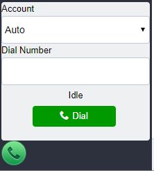
Video & Audio Settings
The audio and videos settings allow users to configure the video / audio codecs, videos resolution, CMOS settings and audio related settings.
Video Settings
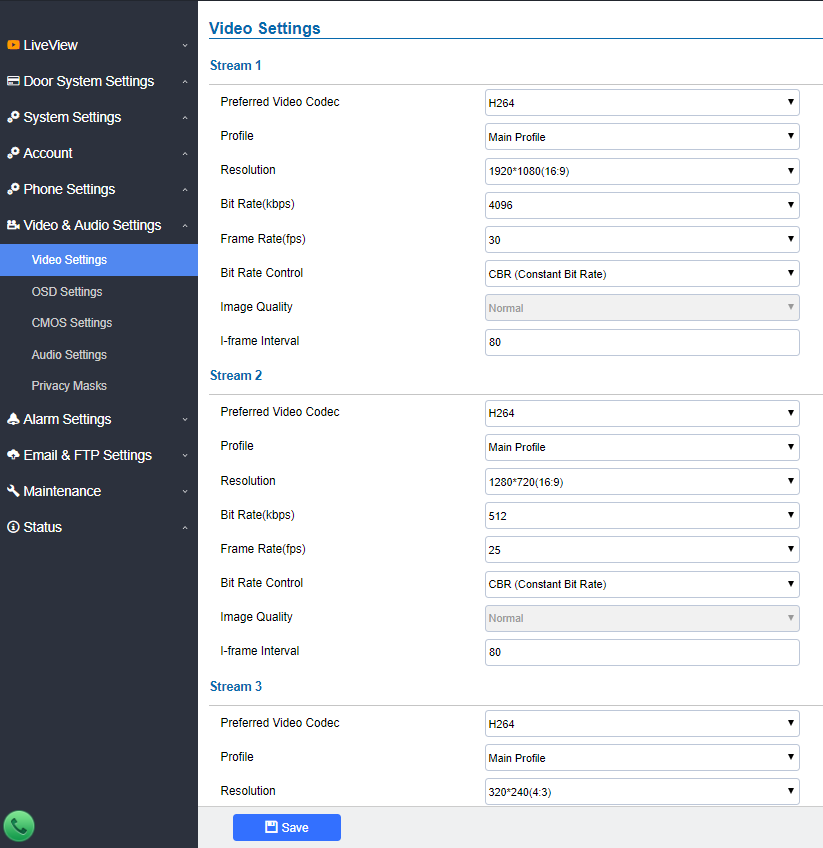
Preferred Video Codec (Stream1) | Selects the videos codecs, the codecs supported are H.264 and MJPEG supported. Default setting is H.264. |
Profile | Selects the H.264 profile. Three profiles are available: Baseline, Main Profile and High Profile. Default setting is “Main Profile”. |
Resolution | Specifies the resolution in pixels used at video image, 1080p or 720p. |
Bit Rate(kbps) | Selects the video bit rate or bandwidth used. |
Frame Rate(fps) | Selects the maximum frame rate used (more data if big frame used). |
Bit Rate Control | Selects the constantly bit rate, or variable bit rate. |
Image Quality | Selects the image quality used when Variable Bit Rate used. |
I-frame Interval | Configures the I-frame interval (suggested 2~3 times of frame rate). |
Preferred Video Codec(Stream2) | Selects the videos codecs, the codecs supported are H.264 and MJPEG supported. Default setting is H.264. |
Profile | Selects the H.264 profile. Three profiles are available: Baseline, Main Profile and High Profile. Default setting is “Main Profile”. |
Resolution | Specifies the resolution in pixels used at video image, 1080p or 720p. |
Bit Rate(kbps) | Selects the video bit rate or bandwidth used. |
Frame Rate(fps) | Selects the maximum frame rate used (more data if big frame used). |
Bit Rate Control | Selects the constantly bit rate, or variable bit rate. |
Image Quality | Selects the image quality used when Variable Bit Rate used. |
I-frame Interval | Configures the I-frame interval (suggested 2~3 times of frame rate). |
Preferred Video Codec(Stream3) | Selects the videos codecs, the codecs supported are H.264 and MJPEG supported. Default setting is H.264. |
Profile | Selects the H.264 profile. Three profiles are available: Baseline, Main Profile and High Profile. Default setting is “Main Profile”. |
Resolution | Specifies the resolution in pixels used at video image, 1080p or 720p. |
Bit Rate(kbps) | Selects the video bit rate or bandwidth used. |
Frame Rate(fps) | Selects the maximum frame rate used (more data if big frame used). |
Bit Rate Control | Selects the constantly bit rate, or variable bit rate. |
Image Quality | Selects the image quality used when Variable Bit Rate used. |
I-frame Interval | Configures the I-frame interval (suggested 2~3 times of frame rate). |
Retrieving Video Streams
- To retrieve video stream via RTSP, users can use the following format :
rtsp://admin:password@IP_GDS3710:Port/X where X=0,4,8 for 1st, 2nd, 3rd streams respectively
- To retrieve MJPEG video stream via http, users can use the following format:
http(s)://admin:password@IP:port/jpeg/stream=X (X=Stream channel 0,1,2)
OSD Settings
OSD Settings (On Screen Display) allows the users to Display time stamp and text on the video screen.
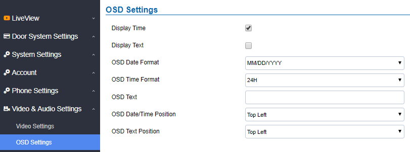
Display Time | When checked, time will be displayed inside the video image. |
Display Text | When checked, inputted text on “OSD Test” will be displayed on the video image. |
OSD Date Format | OSD Date format, choose based on user preference. |
OSD Time Format | OSD Time format, choose based on user preference. |
Input a text (to identify the GDS3710) it will be shown on the screen. Maximum length is 32. | |
OSD Date/Time Position | Show the Date/Time position on the screen. |
OSD Text Position | Show the text position on the screen. |
CMOS Settings
This page configures the CMOS parameters for different scenarios.
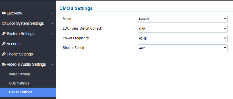
Mode | Pull down to choose “Normal, Low Light, WDR” for different light condition. Default “Normal”. |
LDC | Default “OFF”. When “ON” the display will take a normal shape, but will lose some details located at corner of the original view. |
Select LDC Ratio. Available options: 0.7 ; 0.8 ; 0.9 ; 1.0 ; 1.1 ; 1.2 ; 1.3 Default value is 1.0 | |
Power Frequency | Select the frequency power. 50Hz or 60Hz. |
Shutter Speed | Defines how much time the shutter of the camera or exposed to the light, when taking a screenshot. |
Audio Settings
This page allows users to configure the audio settings.

Preferred Audio Codec | Configures the audio codec. Three codecs are available: PCMU, PCMA and G.722 are supported. |
Adjusts the speaker volume connected. | |
Adjusts the doorbell volume. | |
User can check this option in order to use the custom Doorbell Ringtone. Default Ringtone is used when this option is disabled. | |
| Enable Audio Loopback Test | When enabled, indicating the device is ready for an audio loopback test. Please remember to disable this mode once tested. Note: The OQA Speaker testing has been optimized starting from firmware version 1.0.11.23 |
- Click on
 to upload the ringtone file, then press
- Click on
 to delete the existent custom ringtone.
 - Support upload WAV, PCM audio file(size <= 600K). Format limit to:
WAV:
1. Sample Rate: 8k or 16k.
2. Channel: Mono-channel or Dual-channel.
PCM:
1. Sample Rate: 8K.
2. Channel: Dual-channel.
Note: Empty audio file is not accepted.
Privacy Masks
This page allows users to configure privacy masks up to 4 different regions by selecting different regions requiring privacy mask as displayed on the following figure.
When privacy mask enabled, the video at related region will be masked by black color and no video displayed inside that mask.
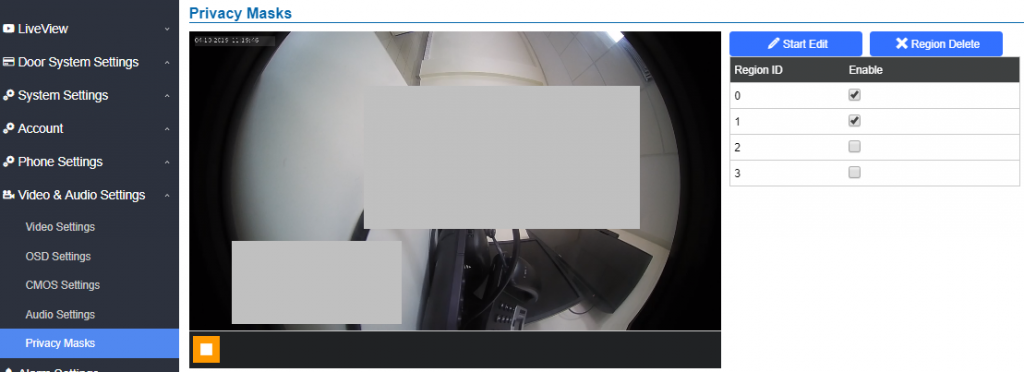
Alarm Settings
This page allows users to configure alarm schedules and alarm actions.
Alarm Events Config
This page allows users to configure GDS371x events to trigger programmed actions within a predefined schedule.
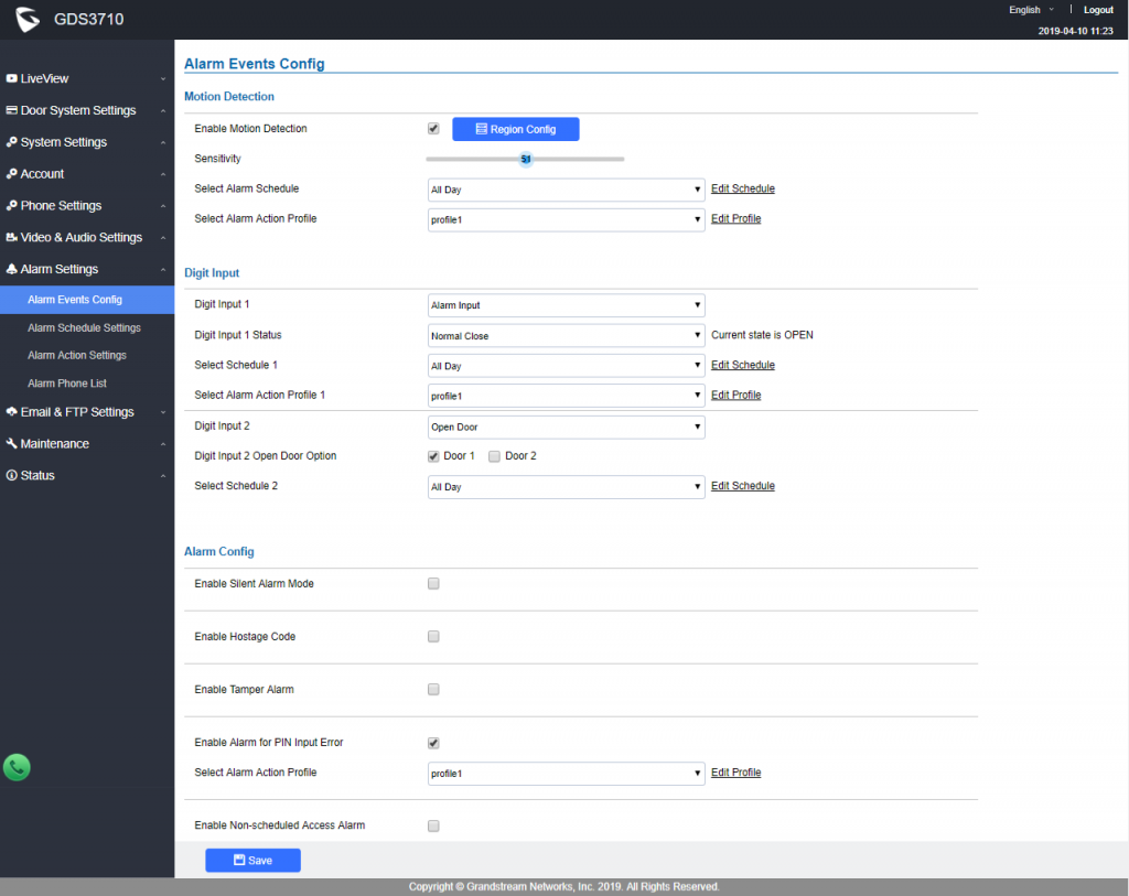
Alarm can be triggered either by motion detection or by GDS371x input.
Motion Detection
Users can select a specific region to trigger the alarm using motion detection.

Enable Motion Detection | Enables the motion detection feature. |
Region Config | Configures the motion detection region. |
Quit Editing | Exits the motion detection region config menu. |
Clear Selected Region | Selects a zone on the screen then click on “Clear” to delete the region. |
Sensitivity | Specifies the region sensitivity (value between 0-100%). |
Select Alarm Schedule | Selects the alarm schedule. |
Select Alarm Action Profile | Selects the programmed Alarm Action profile. |
Digital Input

Digit Input 1 | Selects the Input method (alarm Input or Door Open). Default disabled. Digital Input Port operates in 3 Modes:
Please check Siren alarming when door opened abnormally section. If Digital Input port is connected to a switch, it will not work during the time of power outage, device booting or firmware upgrading. |
Digit Input 1 Open Door Option |
|
By default, Input Digit 1 Status is “Disabled”. | |
Selects the predefined Alarm Schedule. | |
Select Alarm Action Profile 1 | Selects the predefined Alarm Action for Profile 1. |
Digit Input 2 | Selects the Input method (alarm Input or Door Open). Default disabled. Digital Input Port operates in 2 Modes: 1. Alarm Input: Connect various of sensor to trigger alarm. 2. Open Door: Connect a switch to open door from inside. If Digital Input port is connected to a switch, it will not work during the time of power outage, device booting or firmware upgrading. |
Digit Input 2 Open Door Option | When Digital Input is set to Open door then user can select the doors to be affected when Alarm IN 2 is triggered. |
Input Digit 2 Status |
By default, Input Digit 2 Status is “Disabled”. |
Select Schedule 2 | Selects the predefined Alarm Schedule. |
Select Alarm Action Profile 2 | Selects the predefined Alarm Action for Profile 2. |
Alarm Output Duration(s) | Select the duration of the alarm output: 1/2/3/4/5/10/15/20/25/30 seconds. This option is hidden when ALMOUT1 Feature is set to Open Door. Note : this configuration is exclusive for the GDS3710 Model.
|
Enable Silent Alarm Mode
If Silently Alarm Mode is enabled, GDS371x will disable alarm sound and background light for specified alarms types (Digital Input, Motion Detection…) when they are triggered.
Enable/Disable silent alarm mode. | |
Silently Alarm Options | When the silently alarm mode is enabled, users can specify to which alarm options the silently mode will be applied to. The available options are: Digital Input, Motion Detection, Tamper Alarm, and Password Error. |
Hostage Code
Hostage password can be used in a critical situation for instance a kidnaping or an emergency, users need to enter the following sequence to trigger the actions set for the Hostage Mode: “* HostagePassword #”.
Enable Hostage Code | Enable/Disable the Hostage password mode. |
Hostage Code | Configures the password for the hostage mode. |
Select Alarm Action Profile | Select the Alarm action to be taken when the hostage password is typed on the GDS3710 keypad. Note: No sound alarm will be triggered in this mode. |
Tamper Alarm
Tamper alarm is anti-hack from Hardware level. When this option is checked, if the GDS371x is removed from the installation bracket, the built-in Howell Magnetic Switch will function and Tamper Alarm (if enabled and configured, default disabled) will be fired.
This embedded feature in the GDS37xx serves the purpose of enabling the device to detect the separation of these two components, similar to how security magnetic sensors detect the opening and closing of windows or doors.
Enable Tamper Alarm | When activating this mode, GDS371x will keep alarming until the alarm is dismissed. |
Select Alarm Action Profile | Select the type of alarms actions to be triggered for the tamper alarm mode. |
Keypad Input Error Alarm
Enable Keypad Input Error Alarm | Enable/Disable the Input Error Alarm, GDS3710 will trigger alarm actions at every 5 incorrect attempts. |
Select Alarm Action Profile | Select the type of alarms actions to be triggered after 5 incorrect attempts. |
Non-Scheduled Access Alarm
Enable Non-Scheduled Access Alarm | When enabling this feature, GDS3710 will trigger alarm to related administrator to be aware when legitimated users access the door out of the allowed configured schedule |
Select Alarm Action Profile | Select the type of alarms actions to be triggered. |
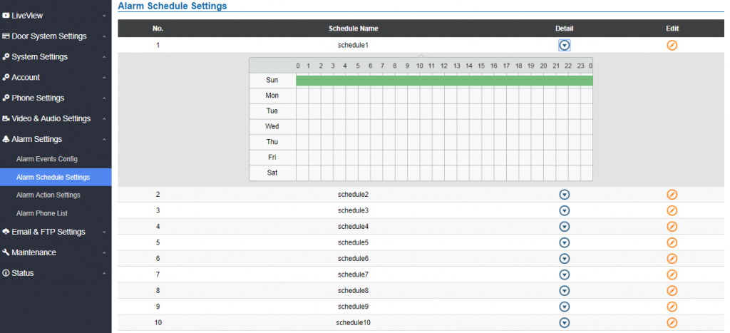
GDS3710 supports up to 10 alarm schedules to be configured, with time span specified by users. User can edit the alarm schedule by clicking
![]() button. Usually the 24 hours’ span is 00:00 ~ 23:59, which is 24 hours’ format.
button. Usually the 24 hours’ span is 00:00 ~ 23:59, which is 24 hours’ format.
Users can copy the configuration to different date during the schedule programming.

Non-authorized RFID Card Access Alarm
When this feature is enabled, any illegal card swiped trying to access the door will trigger alarm based on user’s configuration.
Enable Non-authorized RFID Card Access Alarm | Enable/Disable the option to activate the profile to be executed when unauthorized card swipes. |
Select Alarm Action Profile | Select the type of alarms actions to be triggered after unauthorized card was swiped. |
Alarm Action Settings
This page specifies the configuration of Profile used by the Alarm Actions. A Profile is required before the Alarm Action can take effect.

User can edit the alarm action by clicking ![]() button, the following window will popup.
button, the following window will popup.
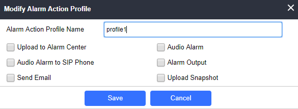
To test an alarm action profile, users can click on
![]() button and the GDS will initiate all actions specified on the select alarm profile.
button and the GDS will initiate all actions specified on the select alarm profile.
Upload to Alarm Center | If selected, the GDS Manager will popup alarm window and sound alarm in the computer speaker. |
Audio Alarm to SIP Phone | If selected, GDS371x will call pre-configured (video or audio) phone and will play sound alarm. |
Send Email | If selected, an email with snapshot will be sent to the pre-configured email destination. |
Audio Alarm | If selected, GDS371x will play alarm audio using built-in speaker. |
Alarm Output | If selected, the alarm will be sent to the equipment (for example: Siren) connected to Alarm Output interface. |
Upload Snapshot | If selected, snapshots at the moment where the event is triggered will be sent to preconfigured destination (e.g.: FTP or email). |
Alarm Phone List
This page allows users to configure the Alarm Phone List, which are phone numbers or extensions list that the GDS371x will call out when event is trigged (e.g.: doorbell pressed).
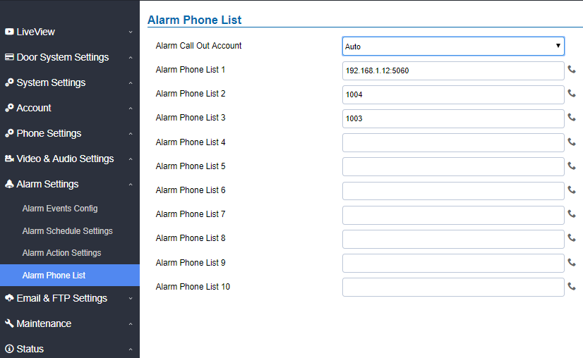
Alarm Call Out Account | Select the SIP Account to be used by the GDS when alarm out is triggered. |
Alarm Phone List 1-10 | Add or delete number from the phone alarm list. (When IP address is used then the port needs to be appended, example: 192.168.1.12:5060). |
Once the event is triggered (Motion Detection, Door Bell Pressed…), the GDS3710 will call the first number, once time out is reached and no answer is returned from the first number, the GDS3710 will try the next number on the list and so on. Once the remote phone answers the call, an alarm will be played to notify users that an event is triggered.
Email & FTP Settings
This page contains Email and FTP Settings.
Email Settings
This page allows users to configure email client to send out an email when the alarm is trigger.
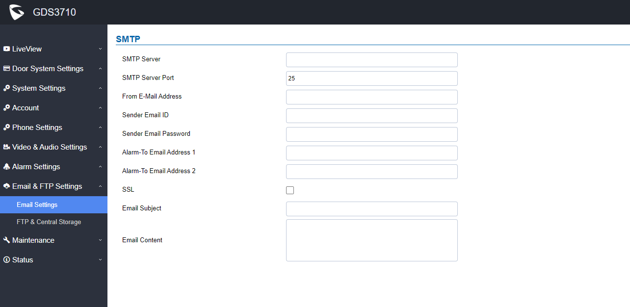
SMTP Server | Configures the SMTP Email Server IP or Domain Name. |
SMTP Server Port | Specifies the Port number used by server to send email. |
From E-mail address | Specifies email address of alarm email sending from, usually client email ID. |
Sender Email ID | Specifies sender’s User ID or account ID in the email system used. |
Sender Email Password | Specifies sender’s password of the email account. |
Alarm-To Email Address 1 | Specifies the 1st email address to receive the alarm email. |
Alarm-To Email Address 2 | Specifies the 2nd email address to receive the alarm email.
|
SSL | Check if the SMTP email server requires SSL. |
Email Subject | Customizes the warning email subject. The default template will be used if the field is left empty |
Email Content | Customizes the warning email content. The default template will be used if the field is left empty |
Email Settings – SMTP Page
FTP & Center Storage
This page allows users to configure the FTP Settings in order to upload capture images.
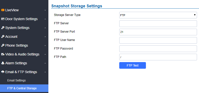
Storage Server Type | Selects whether to upload pictures to the GDS Manager or upload them to the FTP server. |
FTP Server | Configures the IP address of the FTP server when selected to upload images to. |
FTP Server Port | Specifies the FTP address port. |
FTP User Name | Specifies the FTP server account name. |
FTP Password | Specifies the FTP server password. |
FTP Path | Specifies the storage path. |
FTP Test | Click to test the connection with FTP server. |
Note: Blank fields when using Storage Server Type as Central Storage might imply no configuration in GDSManager.
FTP Filenames
When setting up FTP server to store snapshots (when doorbell pressed, or door Unlocked), the GDS will create folder with device MAC address (if multiple GDS3710/GDS3712s are sending snapshots to same FTP server).
In EACH folder based on MAC address or device, the file folder will be created by DATE, to organize and classify the snapshots received during different DATE for easy analysis.
In EACH folder classified with DATE, the snapshot file name is based on following naming schema:
FTP Filename with | Description |
CARD | Meaning that open door operation is using RFID card. |
LPIN (Local PIN) | Meaning that open door operation is via Local PIN (Private PIN, or Unified PIN, or Guest PIN). |
RPIN (Remote PIN) | Meaning that open door operation is via remote PIN or DTMF PIN. (by local or remote SIP extensions, or GS_Wave/Cellphone, or GDSManager if installed in operation). |
RING | Meaning the snapshot taken when somebody pressed the Door Bell button. |
The following figure illustrates the FTP filenames sent to the FTP server when the above operations have been taken:
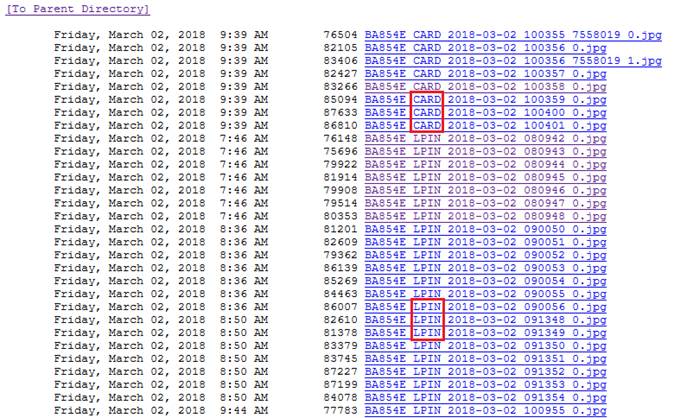
Maintenance Settings
This page shows the GDS371x Maintenance parameters.
Upgrade
This page contains the upgrade and provisioning parameters of the GDS371x.
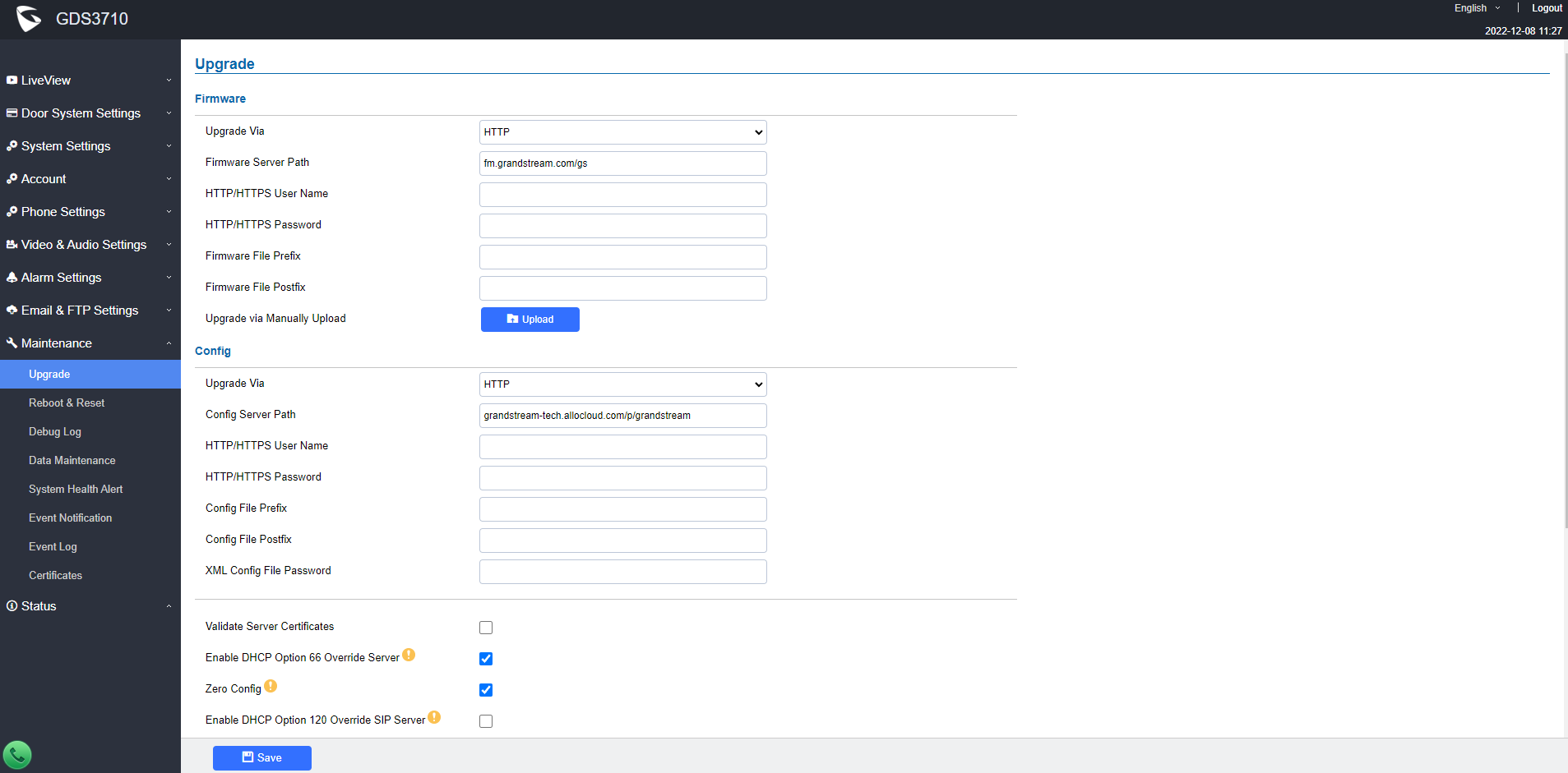
Upgrade Via | Selects the upgrade method (TFTP, HTTP, and HTTPS). |
Firmware Server Path | Configures the IP address or the FQDN of the upgrade server. |
HTTP/HTTPS User Name | The user name for the HTTP/HTTPS server. |
HTTP/HTTPS Password | The password for the HTTP/HTTPS server. |
Firmware File Prefix | Enables your ITSP to lock configuration updates. If configured, only the firmware file with the matching encrypted prefix will be downloaded and flashed into the phone. |
Firmware File Postfix | Enables your ITSP to lock firmware updates. If configured, only the firmware with the matching encrypted postfix will be downloaded and flashed into the phone. |
| Upgrade via Manually Upload | Allows manual uploading of firmware upgrade files. |
Upgrade via | Selects the upgrade method (TFTP, HTTP, and HTTPS). |
Config Server Path | Configures the IP address or the FQDN of the configuration server. |
HTTP/HTTPS User Name | The user name for the HTTP/HTTPS server. |
HTTP/HTTPS Password | The password for the HTTP/HTTPS server. |
Config File Prefix | Enables your ITSP to lock configuration updates. If configured, only the configuration file with the matching encrypted prefix will be downloaded and flashed into the phone. |
Config File Postfix | Enables your ITSP to lock configuration updates. If configured, only the configuration file with the matching encrypted postfix will be downloaded and flashed into the phone. |
XML Config File Password | Specifies the password for the configuration file. |
Validate Server Certificate | Enable this option in order to validate certificate with trusted ones during TLS connection. |
Automatic Upgrade Interval | Specifies the upgrade interval in minutes. |
Enable DHCP Option 66 Override Server | Activates DHCP option 66 to override upgrade/config servers. |
Zero Config | Enables Zero Config feature for auto provisioning. |
Enables DHCP Option 120 from local server to override the SIP Server on the phone. The default setting is enabled. | |
Enables automatic upgrade and provisioning. Set schedule for provisioning for either every X minutes, every day or every week. Default is No. | |
Enable and define the start/End hours of the day and days of the week where the GDS will randomly checking for update. | |
If this option is checked, the Device will not challenge NOTIFY with 401. Default setting is Enabled. |
LED Pattern:
During the upgrade process and starting from firmware 1.0.3.32, the GDS will give indication about the progress of the process using LED lighting as follow:
- Doorbell button blue LED will flash when firmware files are downloading. (the call button will flash in the GDS3712)
- Digit 1,2,3 blue LED will flash during upgrading from 0 to 25%, then stays on. (For the GDS3710)
- Digit 4,5,6 blue LED will flash during upgrading from 25 to 50%, then stays on. (For the GDS3710)
- Digit 7,8,9 blue LED will flash during upgrading from 50 to 75%, then stays on. (For the GDS3710)
- Digit *,0,# blue LED will flash during upgrading from 75 to 100%, then stays on. (For the GDS3710)
- After all key’s blue LEDs light on then flash twice then reboot itself to finish the upgrade process. (For the GDS3710)
Reboot & Reset
This page allows user to reboot and reset the GDS371x.
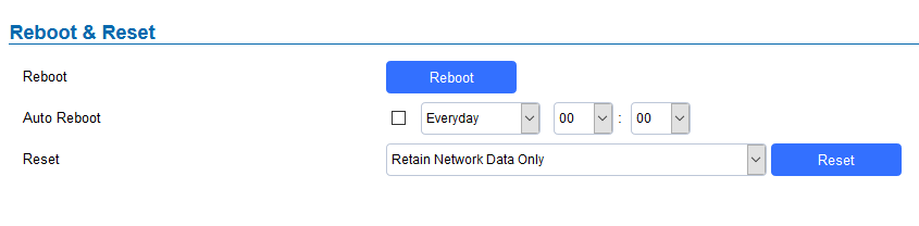
Reboot | When clicked, the GDS371x will restart (soft reboot). |
With this feature, user can configure convenient selected schedule for the device reboot by itself, per week or per day, to make a smooth performance. | |
Reset | There are two options for the reset function. |
Clear All Data | All data will be reset, GDS3710 will be set to factory default. |
Retain Network Data Only | All data will be erased except for Network data like IP address… |
Retain Only Card Information | All data will be erased except for cards information. (Configuration available for the GDS3710 Only ) |
Retain Network Data and Card Information | All data will be erased except for Network Data and Card Information. (Configuration available for the GDS3710 Only ) |
Debug Log
This page allows user to configure SYSLOG to collect information to help troubleshooting issues with GDS371x.
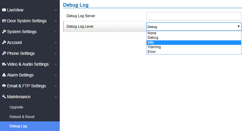
- Five levels of Debugging are available, None, Debug, Info, Warning, Error.
- Once the Syslog Server and the level entered, press “Save” and then Reboot the GDS3710 to apply the settings.
Data Maintenance
This page allows users to manage the GDS371x configuration file by importing/exporting configuration files.
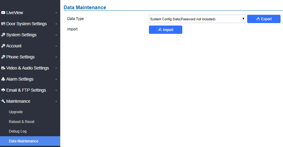
Click on ![]() to save the GDS371x configuration in a predefined directory.
to save the GDS371x configuration in a predefined directory.
System Health Alert
This option allows users to receive alert emails regarding SIP Registration Status of accounts, System Running Status or System Temperature in real time or in a periodic manner.

Enable System Health Alert | When this option is checked, then the GDS will send alert emails regarding the events selected under Event Name section using the already configured [Email Settings]. |
Delivery Method | When set to Realtime, the GDS will be sending successively alert emails every second. When set to Periodic, user can define the time interval between alert emails. |
Email Title | Customize the Email title. Maximum length is 256 character. |
SIP Registration Status | When checked, Email will contain Offline/Online indication for all 4 accounts. |
System Running Status | When checked, Email will contain the system uptime. |
System Temperature | When checked, Email will contain Temperature value of the system in °C and °F, as well as whether the temperature is normal on not. |
Event Notification
This page allows users to configure the event notification details that will be used by GDS3710 to communicate to an HTTP server to log the events. When the feature is enabled and configured, all the event logs will be uploaded to server: RFID open door, PIN open door, SIP Call, Alarm, etc.
Examples:
- After an RFID Card swiping, GDS3710 will send to the configured HTTP server the following HTTP POST containing “Use card open door” event:
POST / HTTP/1.1
Host: 192.168.6.107
Authorization: Basic Og==
Connection: keep-alive
Content-Length: 90
Date: 2017-11-09; Time: 14:07:27; Event describe: Use card open door. Card ID: 378690700.
- After making a Call, when doorbell pressed, GDS3710 will send to the configured HTTP server the following HTTP POST containing “Phone call” event:
POST/HTTP/1.1
Host:192.168.6.107
Authorization:BasicOg==
Connection:keep-alive
Content-Length:62
Date: 2017-11-09; Time: 14:13:12; Event describe: Phone call.
These HTTP POST messages can be used by a 3rd party software to integrate the GDS371x.
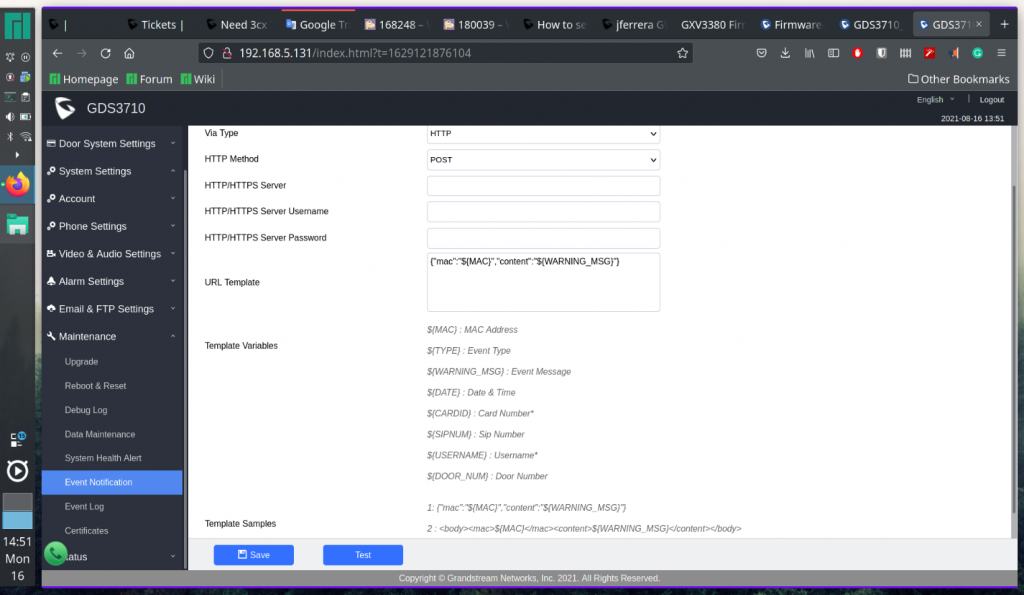
Enable Event Notification | Enables Event Notification feature |
Via Type | Choose which protocol will be used to connect to the logs server (HTTP or HTTPs). |
HTTP Method | Choose which HTTP(s) method will be used to send the logs to the server (POST or GET). |
HTTP/HTTPs Server | Enter the IP address of domain name for the logs server. |
HTTP Server Username | Configure the username of your HTTP(s) server |
HTTP Server Password | Configure the password of your HTTP(s) server |
Specify the template for the event log messages that will be sent to the server, users can use the following variables to customize the message:
|
Event Log
Users could check all device logs directly from the GDS web UI under the menu “Maintenance 🡪 Event log”.
In order to get logs for a specific date interval, select the Start Time and End Time, then select which Event type you want to check using the drop-down list, and click on
![]() to display the records.
to display the records.
The following Event Types are included for filtering:
- Open Door via Card
- Unauthorized door opening attempt
- Visiting Log
- Open Door via PIN
- Open Door via DI
- Open door by SI
- Call Log
- Open Door via Card and PIN
- Open Door via Remote PIN
- Motion Detection
- DI Alarm
- Door & Lock Abnormal Alarm
- Dismantle by Force
- System Up
- Reboot
- Reset
- Config Update
- Firmware Update
- Non-scheduled Access
- Hostage Alarm
- Invalid Password
- Temperature Alarm
- Admin Log
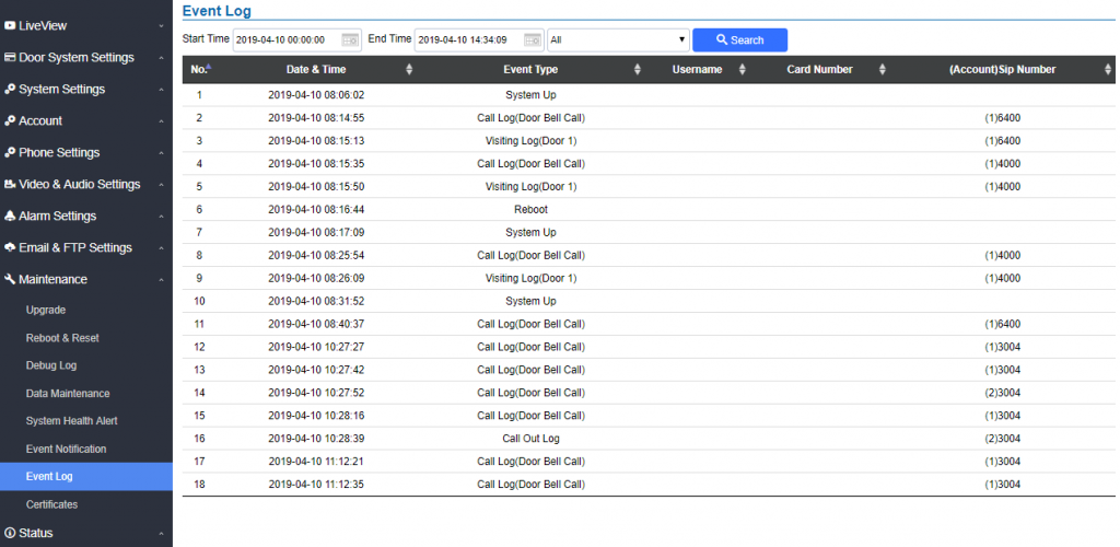
For more information about event logs, please visit this guide.
Certificates
This page allows users to upload up to 6 Trusted CA certificate files which will be trusted by the GDS during SSL exchange.
Also users are allowed to configure the device with custom certificate signed by custom CA certificate under the Custom Certificate section.
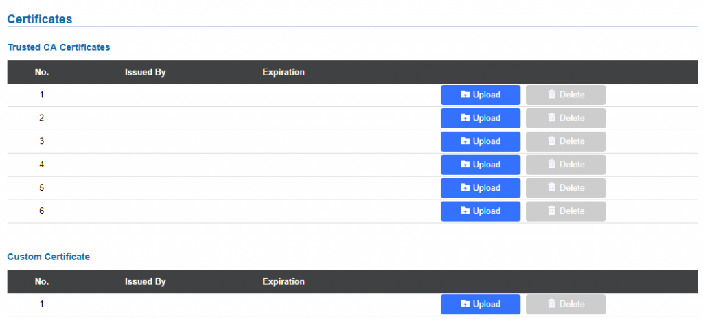
In order to upload your Trusted CA certificate:
Click on ![]() button to upload a file and some related information to the uploaded file will be displayed, such as “Issued by” and “Expiration date”.
button to upload a file and some related information to the uploaded file will be displayed, such as “Issued by” and “Expiration date”.
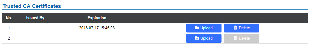
User could press
![]() to delete one of the files.
to delete one of the files.
In order to upload your Custom certificate:
Click on ![]() button to upload a file and some related information to the uploaded file will be displayed, such as “Issued by” and “Expiration date”.
button to upload a file and some related information to the uploaded file will be displayed, such as “Issued by” and “Expiration date”.

User could press ![]() to delete one of the files.
to delete one of the files.
Status
This page displays GDS371x system and network information.
Account Status
This page displays of configured accounts’ SIP user ID, SIP server as well as the SIP Registration status, from Account 1 to Account 4.
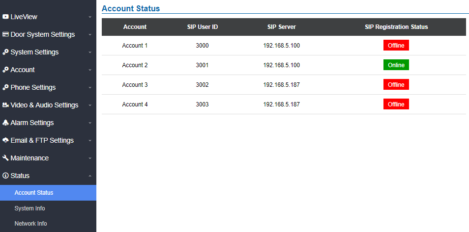
System Info
This page displays information such as the product model, the hardware version, firmware…
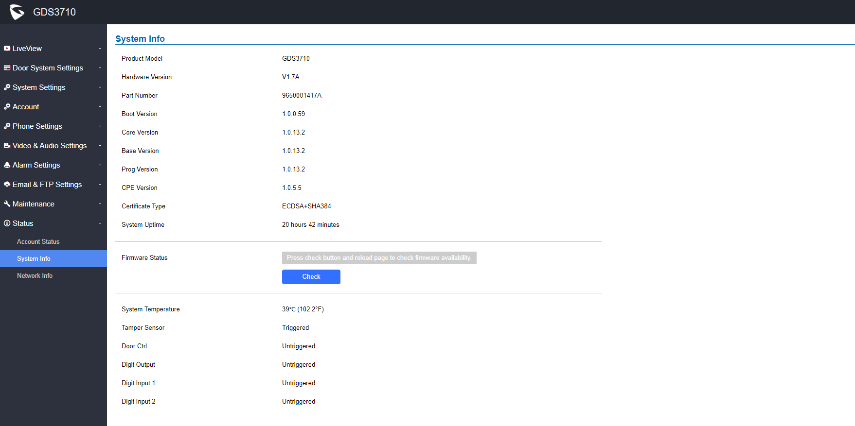
Product Model | Displays the Product Model. |
Hardware Version | Displays the Hardware Version. |
Part Number | Displays the Part Number. |
Boot Version | Displays the Boot Version. |
Core Version | Displays the Core Version. |
Base Version | Displays the Base Version. |
Prog Version | Displays the Prog Version. |
CPE Version | Displays the Customer premise equipement version. |
Certificate Type | Displays the security certificate type used. |
System Up Time | Displays the time since the first boot of the GDS371x. |
SIP Registration Status | Sows whether the SIP account is registered or not. |
Firmware Status | Click the button to check whether the firmware in the firmware server has an updated version, if so, update immediately. |
System Temperature | Shows the current system temperature (in °C and °F). |
Tamper Sensor | Shows if the Temper Sensor is triggered or not. |
Digit Output | Shows if the Alarm Out is triggered or not.
If ALMOUT1 Feature is set to Open Door, then two fields will show up indicating the state of both door 1 and door 2. |
Input Digit 1 | Shows if alarm IN 1 is triggered. |
Input Digit 2 | Shows if alarm IN 2 is triggered. |
System Info page definitions
Network Info
This page displays the network system information of GDS3710.
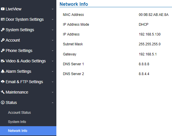
MAC Address | Displays the GDS3710 MAC Address. |
IP Address Mode | Displays the IP address mode used. |
IP Address | Displays the IP address of the GDS3710. |
Subnet Mask | Displays the Subnet Mask used. |
Gateway | Displays the GDS371x Gateway. |
DNS Server 1 | Displays the Preferred DNS Server. |
DNS Server 2 | Displays the secondary DNS Server. |
CONNECTING GDS371x WITH GXV33XX
The GDS371x Door System offers a powerful integration with GXV33xx and allows users to open the door, initiates call to the GDS371x and gets real time audio/video stream.
The GXV33xx can be connected with the GDS371x in two different ways, either using peering mode (without a SIP server) or through a SIP server. For more details, please refer to following guide:
https://documentation.grandstream.com/knowledge-base/connecting-gds37xx-with-gxv33x/
CONNECTING GS WAVE WITH GDS371x DOOR SYSTEM
The GDS371x Door System can interact with the GS Wave softphone application to allow users to open door, initiate call to the GDS371x, offering more mobility during security monitoring and increasing connectivity to essential communications and real-time audio/video stream.
- GS Wave Android: For more details about needed steps for configuring the GDS371x to connect with Grandstream Wave Android™ version, please refer to following guide:
- GS Wave IOS: For more details about needed steps for configuring the GDS371x to connect with Grandstream Wave iOS™ version, please refer to following guide:
https://documentation.grandstream.com/knowledge-base/connecting-gds3710-with-wave-lite-ios-guide/
GDS371x HTTP API
Grandstream Door System supports HTTP API (Application Programming Interface).
For more details, please refer to following guide:
https://documentation.grandstream.com/knowledge-base/gds37xx-http-api/
The document explains in detail the external HTTP-based application programming interface and parameters of functions via the supported method. The HTTP API is firmware dependent. Please refer to the related firmware Release Note for the supported functions.
Administrator Privilege is required, and administrator authentication verification has to be executed before any operation to the related parameter configuration.
FACTORY RESET
Restore to Factory Default via Web GUI
To perform factory reset to the GDS371x via the Web GUI, please refer to following steps:
- Access to GDS371x Web GUI using the using the shipped default password.
- Navigate to Maintenance 🡪Reboot & Reset.
- Select the reset type from Rest drop down menu and press reset button as displayed on the following screenshot.
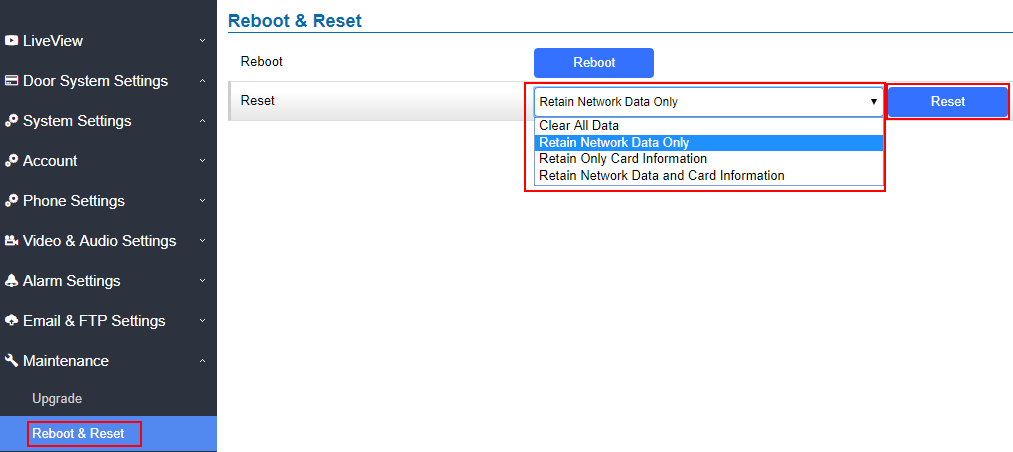
Hard Factory Reset
Some users did not keep the revised password safely and forgot the changed password. Due to GDS3710 did NOT have built-in reset button (Grandstream purposely designed this way to enhance security), this will make the GDS3710 inaccessible even for the true owner who lost the changed password.
Starting from firmware 1.0.2.21, Grandstream introduced a special way to do hard factory reset using the Wiegand Interface Cable shipped with GDS3710. Below is a photo of the normal connection of the provided Wiegand cable.
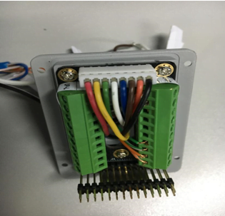
To perform hard factory reset to the GDS371x, please refer to following steps:
- Power OFF the GDS3710.
- Take the provided Wiegand cable, connect (or shorting) the related color wires as illustrated on the following picture. Please make sure the connection is correct and solid:
- Connect WHITE and BROWN cable together.
- Connect GREEN and ORANGE cable together.
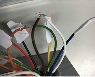
3. Power ON the GDS3710. In about 10 seconds, the key pad LED lighting will change from solid lighting to blinking, the blinking time window is about 30 seconds. The user needs to enter the following key combination *0# while the LED is blinking.
4. After 3 ~ 5 minutes the GDS3710 will finish performing the reset process, then the user can log into the GDS3710 web GUI using the shipped default password.
5. User has to power OFF the GDS3710, unplug the Wiegand cable, power ON the GDS3710 again and make sure the GDS3710 is running correctly.
Hard Factory Reset Using GS Search
The GDS37xx can be reset using the GS Search tool by following these steps :
- Open the GS Search tool that can be downloaded from the Grandstream tools page.
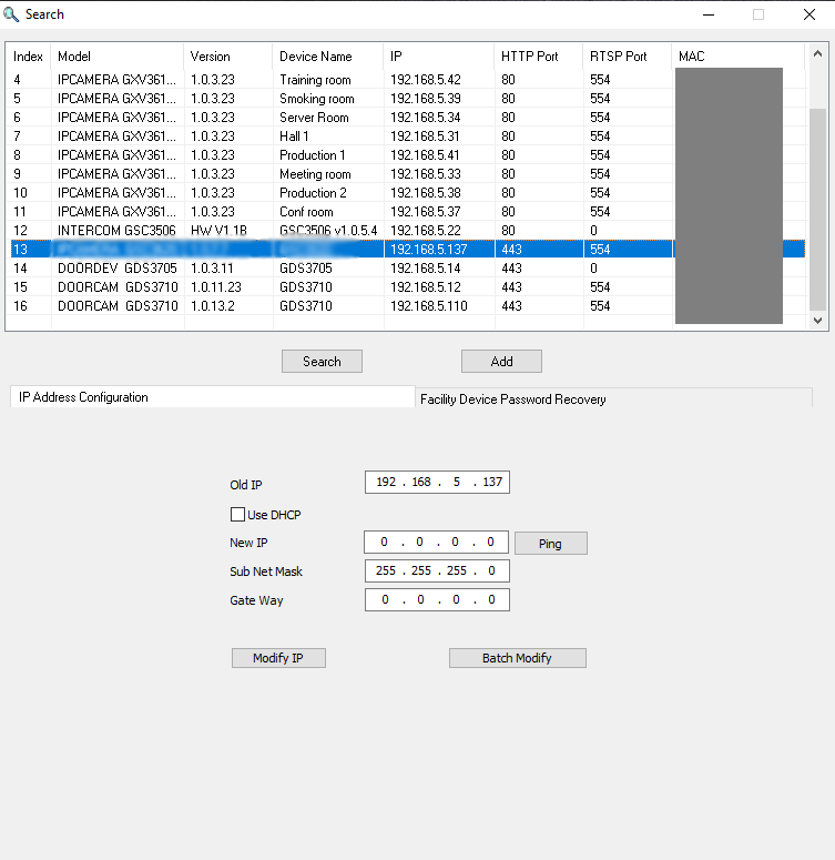
2. Select the device in question, in our example it is the GDS37xx, and then select Facility Device Password Recovery.
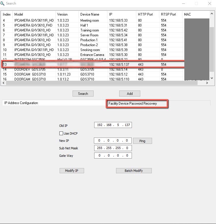
3. Enter the Default password of the unit which can be found in the stick on the device body or in the package box.
4. Perform the reset of the device by clicking the Reset button option.
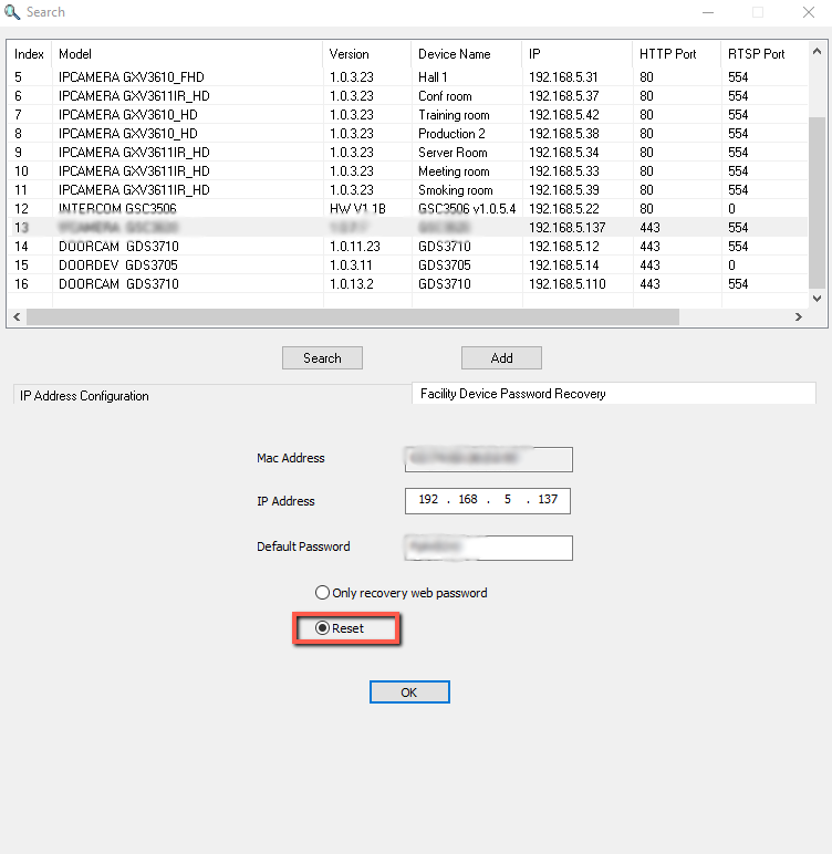
5. You have the possibility to recover the initial default web password as well by selecting the option “only recover web password”
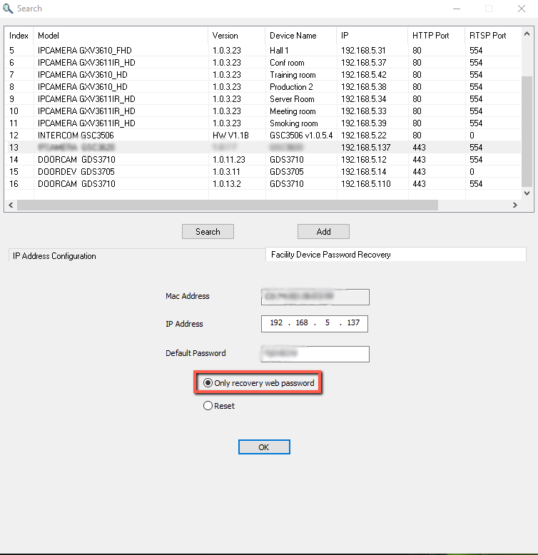
Restore to Factory Default Via SIP NOTIFY
- Access your GDS37xx UI by entering its IP address in your favorite browser.
- Go to Phone Settings # page.
- Enable “Allow Reset Via SIP NOTIFY” by checking this option. (Default is disabled)
- Once a SIP NOTIFY with “event: reset” is received, the GDS37xx will perform factory reset after authentication phase.
g
Restore factory password via special key combination
This feature allows customers to reset the device administrator password to factory default via keypad operation through some special key combination.
When performing this operation, ONLY password will be reset back to factory default. All other setting or parameters will NOT be changed and will remain the same. This feature is specially designed for field engineers or technicians when dispatched in field but for some reason the administrator password is not available therefore not able to access the GDS37xx device to do the related maintenance.
Here are the steps to do such password reset operation via keypad:
Encoding Rules:
Alphabet A – Z mapping to digit 1 – 26 respectively, no difference in lower or up case.
A | B | C | D | E | F | G | H | I | J | K | L | M | N | O | P | Q | R | S | T | U | V | W | X | Y | Z |
1 | 2 | 3 | 4 | 5 | 6 | 7 | 8 | 9 | 10 | 11 | 12 | 13 | 14 | 15 | 16 | 17 | 18 | 19 | 20 | 21 | 22 | 23 | 24 | 25 | 26 |
Operation Steps:
1) When device is idle, input the special keypad combination with format: ***last_6_MAC**#
2) Device will reach restore mode after correct digits in Step 1) entered. The backlight of keypad will flash quickly to tell operator the device is now in password reset/restore mode.
3) Operator will enter the correct decoded default password ending with # with format: default_password_code# via the keypad within 60 seconds.
4) If wrong code combination entered, the GDS37xx will beep with error sound (three short beeps) then exit the password reset mode, and the backlight will stop flashing.
5) If the correct default password decoded entered within 60 seconds, GDS37xx will play a long beep sound (advising correct operation), the device will reboot itself automatically.
6) If keypad entry time out (not finish the input within 60 seconds), the device will exit this password reset mode automatically and stop the backlight flashing. After successful password reset, operator will then be able to log into the GDS37xx webUI with default password, all the configuration inside the device will be the same and will NOT be changed.
For example:
Decoding the string into digits and write to paper before doing the operation:
- Device with last 6 MAC address: 33DDDD
- Decoding the last 6 MAC to digits would be: 334444
- Default password is: xwpxz6AA
- Decoding the default password to digits would be: 2423162426611
1) Enter ***334444**# via keypad, get into the password reset mode, the keypad backlight will flash quickly. 2) Within 60 seconds, enter 2423162426611#, the device will play one long beep then reboot itself.
2) Wait the device finishing boot up, log in the webUI using the default password, xwpxz6AA
CHANGE LOG
This section documents significant changes from previous versions of user manual for GDS3710. Only major new features or major document updates are listed here. Minor updates for corrections or editing are not documented here.
Firmware Version 1.0.13.2
Product name : GDS3712, GDS3710
- Added support for HTTP API request when web access is set to HTTPS. [HTTP API Open Door Compatibility Mode]
- Added support to edit the interval of “Onhook Timer After Remote Open Door(s)”. [Onhook Timer After Remote Open Door(s)]
- Added the ability to configure delay for the snapshots taken when “Door Opened” or “Doorbell Pressed”. [Snapshot Delay when Door Opened(s)] [Snapshot Delay when Doorbell Pressed(s)]
- Added admin audit logging to the event log functionality [Admin Log].
- Added ability to define the TLS protocol level. [Minimum TLS Version] [Maximum TLS Version]
- Added support for System Temperature object identifier in the MIB file. [System Temperature]
- Added improvement for Alarm Email Subject and Text in GDS371x. [Email Subject] [Email Content]
- Added Emergency PIN to Re-enable Keep Door Open. [Emergency PIN]
- Added in WebUI the Certificate Type Information. [Certificate type]
- Added support for access with RTSP password in ONVIF. [ONVIF]
- Added support for 2nd generation certificate. [Custom Certificate]
- Added the use of HTTPS as default CFG file download method to update gen2 cert without manual configuration. [Custom Certificate]
- Added support for SNI extension on TLS. [Check domain certificates]
- Added support for SNMP trap when doorbell button pressed. [SNMP trap port]
- Added “BRIGHTNESS/CONTRAST/SATURATION” setting bar at LiveView page on WebUI. [GDS371x HOME WEB PAGE]
Firmware Version 1.0.11.23
Product name : GDS3712, GDS3710
- Added ability to disable alarm siren sound in triggered alarm call. [Enable/Disable Silent Alarm Mode]
- Added “Keep Door Open” to be configured to use multiple schedules and allow users to choose and apply which schedule to use. [Schedule Open Door]
- Added granular DIGITAL OUTPUT time duration (1s to 4s). [Doorbell Mode]
- Added sending PIN via Wiegand when HTTP API open door executed. [Door Relay Options]
- Added option that no “#” is required after PIN input to make the device behave like a traditional access controller when “Disable Keypad SIP Number Dialing” is selected. [Local PIN Type]
- Added firmware upgrade via manually uploading firmware files from the computer.[Upgrade via Manually Upload]
- Optimized speaker via OQA testing. [Audio Testing]
- Updated CPE version to 1.0.5.5 [CPE Version]
- Added SNMP support. [SNMP Settings]
Firmware Version 1.0.11.15
- Added support of configuring different “Number Called When Door Bell Pressed” entries depending on the time frame or schedule. [Basic Setttings]
Firmware Version 1.0.11.13
- Updated non-scheduled access alarm event log. [Event Log]
Firmware Version 1.0.9.9
- Added support for “SIP URI scheme When using TLS” and “Support SIP Instance ID”. [SIP]
- Increased OSD text length to 32 [OSD]
- Allow using “PIN#” format for Unified PIN when “Disable Keypad SIP Number Dialing” is enabled. [Unified PIN]
- Added support for Secondary SIP Server. [secondary SIP server ]
- Added support for Basic Authentication of HTTP API Remote Open Door. [Basic Settings]
- Added MAC in User-Agent configuration. [Account 1 – 4]
- Added ‘unauthorized card swiped on Wiegand reader’ alert message in event Log. [Event Log]
- Added prompt to prevent empty alarm action profile name. [Alarm Action Settings]
- Added more template variables in Event Notification. [Event Notification]
- Improved private PIN management under the Card Management Web UI. [Show private PIN]
- Added option to choose HTTP method to either POST or GET in Event Notification. [Event Notification]
- Added support for Key Sensitivity Options. [Key Sensitivity Level]
- Added support for Scheduled Auto Reboot. [Auto Reboot]
- Increased whitelist up to 200 per Account. [Account [1-4] White List]
- Added support for One-Way Interlocking Mode. [One-Way Interlocking Mode]
- Added support for door opening with and without call when paired with GSC3570. [Open Door via GDS37xx with or without a SIP Call]
- Added Alarm Action triggering when illegal card swiped. [Alarm Action When Illegal Card Swiped]
- Added Card Number limitation with maximum number to be 2147483647. [Card Number]
- Added Secure Open Door with GDS37xx/GSC3570 setup. [GSC3570 Secure Open Door via GDS37XX/GSC3570 Peering]
- Added Web Relay ON/OFF URL configuration field for some 3rd party Web Relay Door Controlling. [Door Relay Options]
- Set “RTSP password” and “GDSManager Configuration Password” initial value to be GDS37xx default random password. [RTSP Password][GDSManager Configuration Password]
- Added Newfoundland/Canada time zone. [Time Zone]
- Added OpenVPN® support [OpenVPN® Settings]
- Added displaying “Unauthorized door opening attempt” in the Event Log when illegal card used [Event Log]
- Added WebRelay Open Door Feature [Door Relay Options]
- Added reboot/resync via SIP Notify [Disable SIP NOTIFY Authentication]
- Added option to enable PIN/Password display [Enable PIN/Password Display (HTTPS)]
- Added support for “UserName” in HTTP Event Notification [Event Notification]
- Revised SIP Account Name to Display Name [SIP Basic Settings]
- Added support for Cisco QuoVadis/HydrantID CA [Certificates]
- Increased maximum unlock holding time to 1800 seconds (30 minutes). [Basic Settings]
- Added support for anonymous MJPEG stream viewing for each of the three streams. [Enable Anonymous LiveView]
- Enhanced the failover mechanism based on DNS SRV. [DNS Mode]
- Include Holidays on Keep Door Open Schedule for Door 2. [Holiday Mode]
- Added siren alarming function when door opened abnormally. [Connection Examples]
- Added option to only accept incoming SIP call from Proxy/Server. [Accept Incoming SIP from Proxy Only]
- Added support for including Holidays at Keep Door Open schedule. [Keep Door Open]
Added reset/restore factory default password via special keypad combination operations. [FACTORY RESET]
- Added ability to separate webUI credentials from the GDSManager credentials. [GDSManager Configuration Password]
- Added G.729 audio codec support. [Technical Specifications] [Preferred Vocoder]
- Added ability to enable multiple audio codecs simultaneously and specify priority of codecs. [Preferred Vocoder]
- Added “Schedule” for firmware upgrade and provisioning. [Upgrade]
- Added support for randomize firmware upgrade and provisioning. [Upgrade]
- Added support for Voice Frame per TX in the audio settings. [Voice Frame Per TX]
- Added option to keep keypad blue light ON/OFF based on schedule. [Door System Settings]
- Added support for DHCP Option 120. [Enable DHCP Option 120 Override SIP Server]
- Added support for reregister before expiration option. [Re-register before Expiration (s)]
- Added support for anonymous RTSP Live View. [Enable Anonymous LiveView]
- Added support for DHCP Option 42. [Allow DHCP Option 42 to override NTP server]
- Added support for 4 SIP accounts. [Account]
- Added option to configure DTMF Payload value. [DTMF Payload Type]
- Added option to disable outbound proxy route header. [Outbound Proxy Mode]
- Added support for Packetization Mode 0. [SIP Packetization Compatibility Mode]
- Added support for “Normal Open” or “Normal Close” setting when Alarm Out1 is set to Open Door. [ALMOUT1 Status]
- Added support for System Health Alerts via Email. [System Health Alert]
- Added option to upload custom doorbell ringtone. [Enable Custom Doorbell Ringtone]
- Added option to set Schedule for “Local PIN to Open Door”. [Local PIN to Open Door Schedule]
- Added support for CSV format when Importing/Exporting Card user data. [Card Management]
- Added support for Anonymous Snapshot. [Enable Anonymous LiveView]
- Enhanced security by only allowing numbers existing under “White List” to open the door remotely when call is initiated from GDS3710. [Remote PIN to Open the Door]
- Added Boot version information into System status. [Boot Version]
- Added Alarm_Out port (COM1 interface) to be used as Open Door 2. [Using Alarm Out (COM 1) to Control a Second Door]
- Added option to Enable/Disable WebUI access. [Disable Web Access]
- Added option to define number of snapshots to be uploaded when opening door. [Number of Snapshots when Door Opened]
• Added option to specify digital input to be normal Open or normal Close. [Input Digit 1 Status]
• Added ability to set schedule for Alarm In door opening. [Select Alarm Schedule]
• Added support for using Digit Only as Private PIN. [Local PIN Type]
• Added option to configure “No Key Entry Timeout”. [No Key Input Timeout]
• Added ability to email snapshot when door opened. [Snapshot when Door Opened]
- Added option to allow anonymous viewing. [Enable Anonymous LiveView]
- Added option to configure payload type for H.264. [H.264 Payload Type]
- Extended VLAN tag range from 0 to 4094. [Layer 2 QoS 802.1Q/VLAN Tag]
- Added option to use Emergency PIN to overwrite “Keep Door Open” schedule and lockdown. [Emergency PIN]
- Added ability to configure device with custom certificate signed by custom CA certificate. [Certificates]
- Added support for special character “@” in the SIP User ID. [SIP User ID]
- Added SIP NOTIFY to factory reset the GDS3710. [Allow Reset Via SIP NOTIFY] [Restore to Factory Default Via SIP NOTIFY]
- Added event log showing the users (Username) opening door via private PIN. [Event Log]
- Added support for Parallel Hunting when doorbell pressed [Door Bell Call Mode]
- Enhanced HTTP Event Notification details: Added “CARDID” and “SIPNUM” [URL Template]
- Add support for TLSv1.2
- Added option to assign a schedule to the doorbell. [Press Doorbell Schedule]
- Added option to set the maximum number of digits dialed. [Maximum Number of Dialed Digits]
- Added support for video live view on Chrome/Firefox with no Plugin required. [Live View Page]
- Added option to send Snapshot via Email when doorbell pressed. [Snapshot when Doorbell Pressed]
- Added RTCP/RTCP-XR for SIP Call to meet Cloud Solution Service Provider. [Enable RTCP]
- Added alarm notification of non-scheduled access users. [Non-Scheduled Access Alarm]
- Added Keep Door Open section. [Keep Door Open]
- Added MJPEG Authentication Mode. [JPEG Authentication Mode] [Live View Page]
- Added LED lighting indication pattern for firmware upgrade process. [Upgrade]
- Increased the maximum allowed whitelist numbers to 30 records with 20-digit length for each number [Account [1-4] White List]
- Added Support for HTTP command to Open Door. [Enable HTTP API Remote Open Door]
- Added display device logs at GDS web UI. [Event Log]
- Added valid start/end dates for Card Management. [Card Management]
- Added “Test” button for Alarm Action. [Alarm Action]
- Added “Alarm IN/OUT Status” display at GDS “Status” page UI.
- [Added Self-defined Even Notification Message. [Event Notification]
- Added ability to upload Trusted CA certificate files. [Certificates]
- Added support for multi-channel call mode. [Enable Multi-channel Call Mode]
- Added option to enable/disable certificate validation. [Certificates]
- Added Standard Mode and Broadsoft Mode in SIP Settings, Broadsoft Supported. [Special Feature]
- Added card ID number and phone number reported in event log message. [Event Notification]
- Added “Click-to-Dial” feature support. [Click-To-Dial]
- Added option to disable alarm sound at phone side when event trigger SIP call to the phone. [Enable two-way SIP Calling]
- Increased maximum characters to 256 in “Number called when doorbell pressed” to allow serial hunting of SIP extensions or IP address with port or mixing of both, with each ring several seconds before going next. [Number Called When Door Bell Pressed]
- Added feature to capture snapshot when doorbell pressed. [Snapshot when Doorbell Pressed]
- Added feature to disable keypad input (lock keypad) and ONLY doorbell button can be pressed. [Disable Keypad (except the Doorbell Button)]
- Added option to disconnect call automatically after door open event. [Enable On Hook After Remote Door Opened]
- Issuing Mode automatically. [Card issuing State Expire Time(m)]
- Added ability for whitelist entries to open door using remote PIN. [Account [1-4] White List]
- Added if schedule disabled, GDS3710 will bypass the option to open door. [Group overrides Schedule]
- Implemented the HTTP Upload (RFID card) Log Event support for 3rd party Software Integration. [Event Notification]
- No major changes.
- Allow config and call IP address format on SIP field when dialing the Virtual Number. [SIP Number]
- Added “Silent Alarm” Mode. [Enable Silent Alarm Mode]
- Added option Backup/Restore including all passwords like SIP/FTP/Remote Access, etc. [Data Maintenance]
- Added schedule support for Card and PIN. [Schedule]
- Added LLDP support. [Enable LLDP]
- Added database automatic backup and synchronization.
- Modified WebGUI style.
- Added card information batch delete option in the WebGUI. [Users Operation]
- Added option to enable “Motion Detection”, “Tamper Alarm” and backlight partially light. [Tamper Alarm] [Motion Detection] [Enable Background Light]
- Added card user limitation up to 2000 and Group Limit to 50. [Card Management]
- Added Card and PIN schedule configuration Central Mode. [Central Mode]
- Added LDC Ratio Control and Adjustment. [LDC Ratio]
- Expended the range of Ring timeout. [Ring Timeout]
- Added option to disable Auto Answer. [Auto Answer]
- Updated the “DingDong” tone when doorbell pressed.
- Added function to check the default value.
- Added Factory Reset via special procedures. [Hard Factory Reset]
- Added file upload and download (card information, configuration etc.) can be executed after authentication. [Card Management]
- Added support of ONVIF Profile S.
- Added “Privacy Mask” support in Motion Detection Setting. [Privacy Masks]
- Updated OCX plugin engine to Version 3.1.0.74
- Added DTMF Open Door control option in WebGUI [Enable DTMF Open Door]
- Added HTTP API support [GDS3710 HTTP API].
- Optimized HTTP API for Card Management.
- Added “Enable Blue Doorbell Light” option in the webGUI. [Door System Settings]
- Added switch on the doorbell blue light by configured time period of the day. [Door System Settings]
- Implemented “Silent Alarm” mode. [Enable Silent Alarm Mode]
- Added back DTMF Open Door as optional choice, with user acknowledging the security risk. [Enable DTMF Open Door]
- Revised “Alarm Output Duration(s)” choice option as 5/10/15/20/25/30 seconds.
- Added folder creation and file arrangement if multiple GDS3710s are uploading snapshots to FTP server.
- Added DTMF audio playing when key be pressed. [Key Tone Type]
- Separated volume control under Web GUI -> Audio Settings. [System Volume][Doorbell Volume]
- Added “Audio, Snapshot, Recording and File Path Saved” operation with icons at Live View webpage. [Live View Page]
- Added “show password” feature when the eye icon be clicked in the webGUI.
- Added prompt popup message when capture button clicked.
- Use different email title to separate the Motion Detection and Temperature Out of the Range alarm.
- Set initial value of “0” for Virtual Number and SIP number if user leaving the field empty. [Virtual Number][SIP Number]
- Added support open door remotely via GDS Manager utility (after GDS Manager version 1.0.0.78)
- Supported GXP color phone JPEG_Over_HTTP with encryption and authentication. This feature is pending on GXP/UCM6xxx firmware availability. Currently this feature does not support 3rd party PBX if SIP extension is used in Open Door configuration.
- Added SSH support with default TCP port 22. [Enable SSH][SSH Port]
- Added GS_Wave (Android/iOS) Application support for Open Door. [CONNECTING GS WAVE WITH GDS3710 DOOR SYSTEM].
- Enhanced webGUI login process and added random default password.
- Enhance security by disable the DTMF to open door
- Added support of sending DTMF tone in SIP calling (RFC2833, SIP INFO). [Enable DTMF]
- This is the initial version for GDS371x.