

Thank you for purchasing Grandstream GRP260X Lite Series IP Phones.
The GRP Carrier-Grade IP Phone series is designed with zero-touch provisioning for mass deployment and centralized cloud management via GDMS. Engineered for on-site or remote desktop workers, this series offers a sleek design with next-generation communication features, including 5-way audio conferencing, full HD audio on both speaker and handset, AI Noise Reduction, GS-FEC packet loss resistance, and native WireGuard VPN support.
PRODUCT OVERVIEW
Feature Highlights
The following table compares the major features of the GRP260X Lite phones:
Feature | 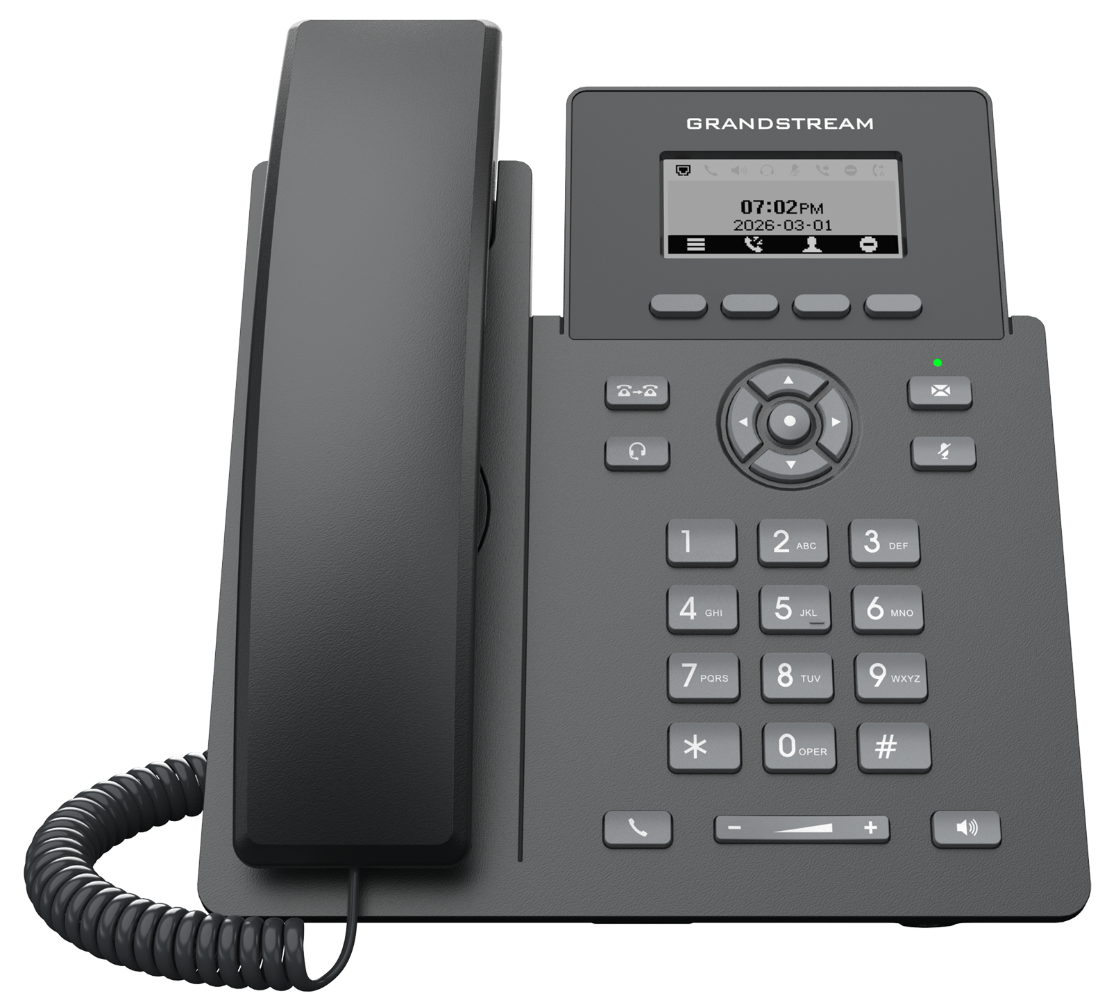 GRP2601L | GRP2601LP | GRP2601LW | 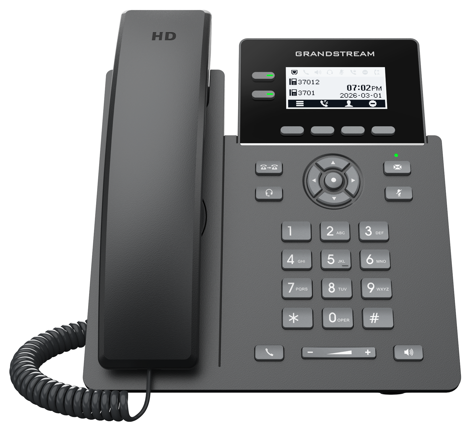 GRP2602LP | GRP2602LG |
SIP Accounts / Lines | 2 / 2 | 4 / 2 | |||
Line Keys | None | 2 (Dual-color LED) | |||
Display | 2.41″ LCD (132×48) | 2.41″ Backlit LCD (132×48) | |||
Network Speeds | Dual 10/100 Mbps | Dual 10/100/1000 Mbps (Gigabit) | |||
PoE Support | No | Integrated PoE (Class 1) | No | Integrated PoE (Class 1) | |
Wi-Fi | Not supported | Wi-Fi 6 (2.4 GHz 802.11ax) | Not supported | ||
Audio & Codecs | HD Audio, Opus, GS-FEC, AI Noise Reduction | Full HD Audio, Opus, GS-FEC, AI Noise Reduction | |||
Conferencing | 5-way audio | ||||
VPN Support | WireGuard VPN | ||||
Headset Port | RJ9 with EHS | ||||
GRP260x Lite Features at a glance
Technical Specifications
The following table summarizes all the technical specifications including the protocols/standards supported, voice codecs, telephony features, languages, and upgrade/provisioning settings for the GRP260X Lite series.
- GRP2601L/GRP2601LP/GRP2601LW Technical Specifications
GRP2601L | GRP2601LP | GRP2601LW | ||
Basic | Unit Dimension | 202 mm × 180 mm × 63.4 mm (7.95″ × 7.09″ × 2.50″)(L × W × H)(With Handset) | ||
Package Dimension | 253 mm × 206.5 mm × 69 mm (9.96″ × 8.13″ × 2.72″)(L × W × H) | 242 mm × 206.5 mm × 59 mm (9.53″ × 8.13″ × 2.32″)(L × W × H) | 253 mm × 206.5 mm × 69 mm (9.96″ × 8.13″ × 2.72″)(L × W × H) | |
Unit Weight | 650 g (1.43 lb) | 650 g (1.43 lb) | 651 g (1.44 lb) | |
Package Weight | 860 g (1.90 lb) | TBD | 900 g (2.0 lb) | |
Installation Methods | Desktop, Wall Mount (Wall mount bracket sold separately) | |||
Physical Features | Graphic Display | 2.41 inch (132 × 48) LCD | ||
Feature Keys |
| |||
Base Stand | Yes, 1 angle position available (45°) | |||
Ports | Network Ports |
|
|
|
Auxiliary Ports |
| |||
Power and Energy | Universal Power Adapter | Input: 100–240 V AC, 50–60 Hz; Output: 5 V DC, 600 mA | ||
PoE | N/A | IEEE 802.3af Class 1, 3.84 W; IEEE 802.3az (EEE) | N/A | |
Connectivity | Wi-Fi | N/A | N/A | Single-band 2.4 GHz (802.11b/g/n/ax) |
Environmental Endurance | Operating Temperature | 0 °C to 40 °C (32 °F to 104 °F) | ||
Storage Temperature | -10 °C to 60 °C (14 °F to 140 °F) | |||
Humidity | 10%–90%, non-condensing | |||
Certification | Compliance | CE, FCC, IC, RCM | ||
Protocols and Standards | Network Protocols | IPv4, IPv6, HTTP/HTTPS, ARP, ICMP, DNS (A record, SRV, NAPTR), DHCP, SSH, TFTP, NTP, STUN, TURN, ICE, SIMPLE, LLDP-MED, LDAP, TR-069, SNMP, 802.1X | ||
VoIP Protocols | SIP RFC3261 (over UDP/TCP/TLS), RTP/RTCP, RTCP-XR, RTCP-MUX, SDES-SRTP, DTLS-SRTP | |||
QoS | Layer 2 QoS (802.1Q, 802.1p) and Layer 3 (ToS, DiffServ, MPLS) QoS | |||
Wi-Fi Encryption | N/A | N/A | WEP, WPA/WPA2 (Personal/Enterprise), WPA3 (Personal/Enterprise) | |
Security |
| |||
Provisioning and Interoperability | Deployment | Mass provisioning using GDMS/TR-069 or AES encrypted XML configuration file | ||
Maintenance | Firmware upgrade via FTP, TFTP, TFTPS, HTTP and HTTPS | |||
Interoperability | Fully interoperable with major UC platforms including BroadSoft, Metaswitch, Kandy, 3CX, Zoom, NetSapiens, RingCentral, Asterisk, Freeswitch and openSIPS | |||
Audio Features | Voice Codecs | G.729A/B, G.711µ/a-law, G.726, G.722 (wide-band), G.723.1, iLBC, Opus (with in-band FEC) | ||
Audio Capabilities |
| |||
Features | Directory | Downloadable phonebook (XML, LDAP, up to 500 items), call log (up to 200 records) | ||
Call Management | Hold, transfer, forward, call park, call pickup, call waiting, auto answer, off-hook auto dial, click-to-dial | |||
Collaboration | 5-way conferencing, shared-call-appearance (SCA), bridged-line-appearance (BLA) | |||
Customization | Personalized music ringtones and music on hold | |||
System and Administration | Hot-desking, flexible dial plan, server redundancy, failover | |||
Advanced Features |
| |||
Localization | Multi-Language | Arabic, Catalan, Chinese (Simplified), Chinese (Traditional), Croatian, Czech, Dutch, English, French, German, Greek, Hebrew, Hungarian, Italian, Japanese, Korean, Latvian, Polish, Portuguese, Russian, Slovak, Slovenian, Spanish, Swedish, Turkish, Ukrainian | ||
Standard Items | Primary Unit |
| ||
Power and Cable |
| 1 × Network Cable |
| |
Manual and License |
| |||
GRP2601L/GRP2601LP/GRP2601LW Technical Specifications
- GRP2602LP/GRP2602LG Technical Specifications
GRP2602LP | GRP2602LG | ||
Basic | Unit Dimension | 202 mm × 180 mm × 63.4 mm (7.95″ × 7.09″ × 2.50″)(L × W × H)(with handset) | |
Package Dimension | 242 mm × 206.5 mm × 59 mm (9.53″ × 8.13″ × 2.32″)(L × W × H) | 253 mm × 206.5 mm × 69 mm (9.96″ × 8.13″ × 2.72″)(L × W × H) | |
Unit Weight | 670 g (1.48 lb) | ||
Package Weight | 830 g (1.83 lb) | 880 g (1.94 lb) | |
Installation Methods | Desktop, Wall Mount (Wall mount bracket sold separately) | ||
Physical Features | Graphic Display | 2.41 inch (132 × 48) LCD with backlight | |
Feature Keys |
| ||
Base Stand | Yes, 1 angle position available (45°) | ||
Ports | Network Ports |
|
|
Auxiliary Ports |
| ||
Power and Energy | Universal Power Adapter | Input: 100–240 V AC, 50–60 Hz; Output: 5 V DC, 600 mA | |
PoE | IEEE802.3af Class 1, 3.84 W; IEEE802.3az (EEE) | ||
Environmental Endurance | Operating Temperature | 0 °C to 40 °C (32 °F to 104 °F) | |
Storage Temperature | -10 °C to 60 °C (14 °F to 140 °F) | ||
Humidity | 10%–90%, non-condensing | ||
Certification | Compliance | CE, FCC, IC, RCM | |
Protocols and Standards | Network Protocols | IPv4, IPv6, HTTP/HTTPS, ARP, ICMP, DNS (A record, SRV, NAPTR), DHCP, SSH, TFTP, NTP, STUN, TURN, ICE, SIMPLE, LLDP-MED, LDAP, TR-069, SNMP, 802.1X | |
VoIP Protocols | SIP RFC3261 (over UDP/TCP/TLS), RTP/RTCP, RTCP-XR, RTCP-MUX, SDES-SRTP, DTLS-SRTP | ||
QoS | Layer 2 QoS (802.1Q, 802.1p) and Layer 3 (ToS, DiffServ, MPLS) QoS | ||
Security |
| ||
Provisioning and Interoperability | Deployment | Mass provisioning using GDMS/TR-069 or AES encrypted XML configuration file | |
Maintenance | Firmware upgrade via FTP, TFTP, TFTPS, HTTP and HTTPS | ||
Interoperability | Fully interoperable with major UC platforms including BroadSoft, Metaswitch, Kandy, 3CX, Zoom, NetSapiens, RingCentral, Asterisk, Freeswitch, and openSIPS | ||
Audio Features | Voice Codecs | G.729A/B, G.711μ/a-law, G.726, G.722 (wide-band), G.723.1, iLBC, Opus (with in-band FEC) | |
Audio Capabilities |
| ||
Features | Directory | Downloadable phonebook (XML, LDAP, up to 500 items), call log (up to 200 records) | |
Call Management | Hold, transfer, forward, call park, call pickup, call waiting, auto answer, off-hook auto dial, click-to-dial | ||
Collaboration | 5-way conferencing, shared-call-appearance (SCA), bridged-line-appearance (BLA) | ||
Customization | Personalized music ringtones and music on hold | ||
System and Administration | Hot-desking, flexible dial plan, server redundancy, failover | ||
Advanced Features |
| ||
Localization | Multi-Language | Arabic, Catalan, Chinese (Simplified), Chinese (Traditional), Croatian, Czech, Dutch, English, French, German, Greek, Hebrew, Hungarian, Italian, Japanese, Korean, Latvian, Polish, Portuguese, Russian, Slovak, Slovenian, Spanish, Swedish, Turkish, Ukrainian | |
Standard Items | Primary Unit |
| |
Power and Cable | 1 × Network Cable |
| |
Manual and License |
| ||
GRP2602LP/GRP2602LG Technical Specifications
GETTING STARTED
This chapter provides basic installation instructions, including the list of the packaging contents and information for obtaining the best performance with the GRP260X Lite IP phones.
Equipment Packaging
GRP260X Lite Phone Package Content |
|
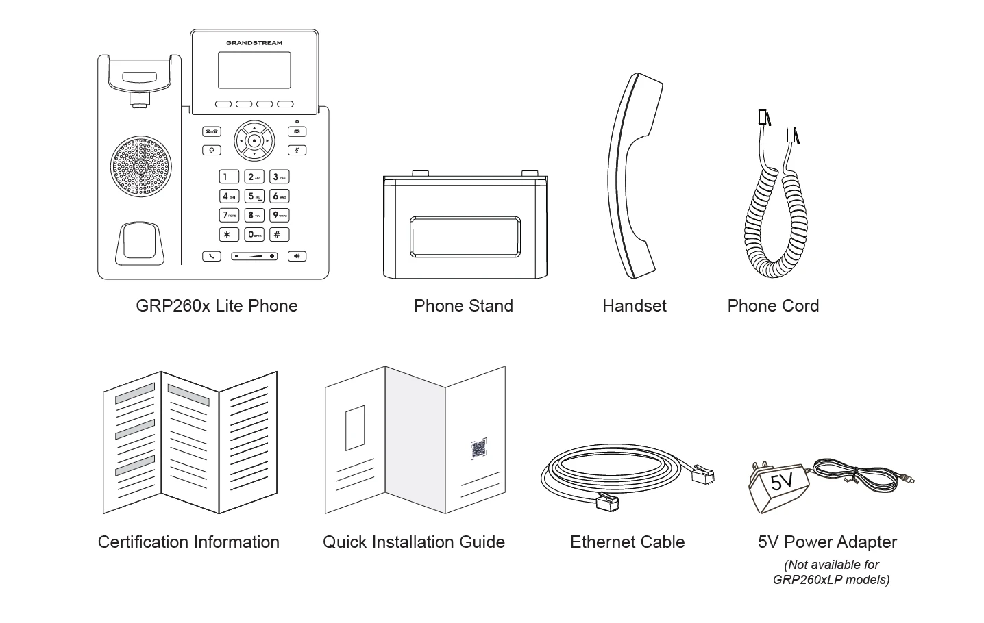
GRP260X Lite Phone Setup
The GRP260X Lite phones can be installed on the desktop using the phone stand or attached to the wall using the slots for wall mounting.
Using the Phone Stand
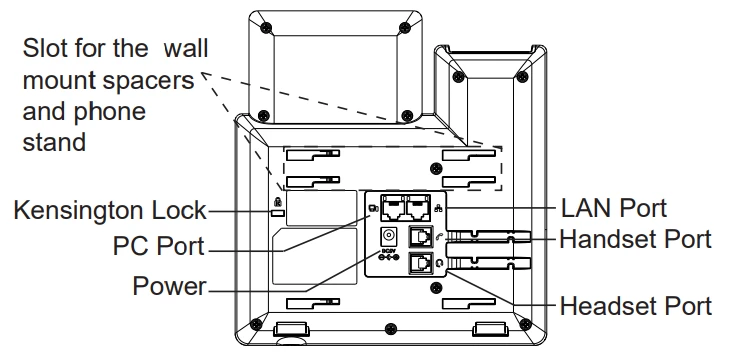
To install the phone on the table with the phone stand, attach the phone stand to the bottom of the phone where there is a slot for the phone stand. (Upper half, bottom part).
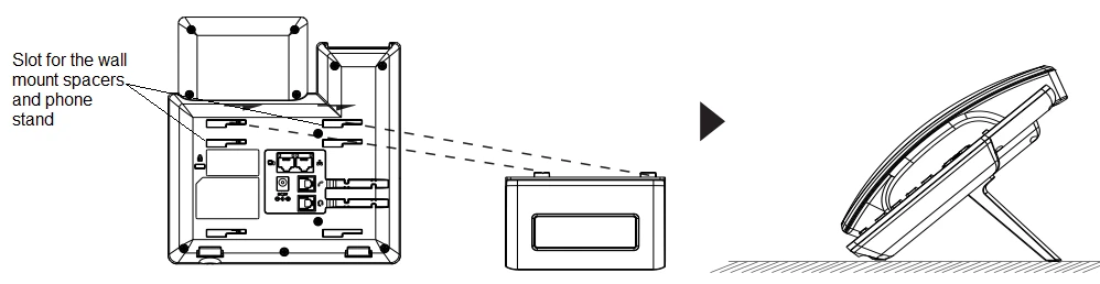
Using the Slots for Wall Mounting
- Attach the wall mount spacers to the slot for wall mount spacers on the back of the phone.
- Attach the phone to the wall via the wall mount hole.
- Pull out the tab from the handset cradle (See figure below).
- Rotate the tab and plug it back into the slot with the extension up to hold the handset while the phone is mounted on the wall (see figure below).
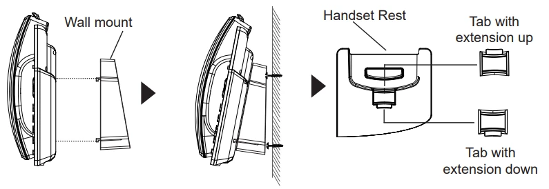
Connecting the GRP260X Lite
To set up the GRP260X Lite, follow the steps below:
- Connect the handset and main phone case with the phone cord.
- Connect the LAN port of the phone to the RJ-45 socket of a hub/switch or a router (LAN side of the router) using the Ethernet cable.
- Connect the 5V DC output plug to the power jack on the phone. Plug the power adapter into an electrical outlet. If a PoE switch is used in step 3, this step could be skipped (For GRP2601LP, GRP2602LP, and GRP2602LG).
- The LCD will display the Grandstream logo. Before continuing, please wait for the date/time display to show up.
- Using the phone-embedded web server or keypad configuration menu, you can further configure the phone using either a static IP or DHCP.
Using Wi-Fi (GRP2601LW only):
- On the LCD menu, navigate to Settings → Wi-Fi settings and enable Wi-Fi.
- Select Wi-Fi Network and the phone will automatically start scanning within the range.
- A list of Wi-Fi networks will be displayed. Select the desired network, and if required, enter the correct password to connect.
- Users can add and connect to a hidden network by accessing Wi-Fi Network and then pressing the Add softkey. Then enter the Network’s information.
Configuration via Keypad
To configure the LCD menu using the phone’s keypad, follow the instructions below:
- Enter MENU options: When the phone is idle, press the round MENU button or Menu Softkey to enter the configuration menu.
- Navigate to the menu options: Press the arrow keys UP/DOWN keys to navigate in the menu options.
- Enter/Confirm selection: Press the round MENU button to enter the selected option.
- Exit: Press the Return Softkey to exit to the previous menu.
- Return to the Home page.
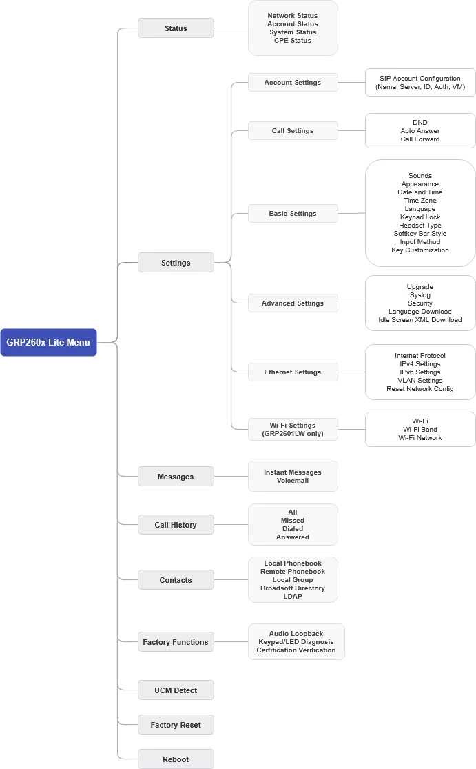
The MENU options are listed in the following table.
Status | Displays account status, network status, software version number, and Hardware:
|
Settings | Settings sub menu contains the following options:
|
Messages | The messages menu contains the following:
|
Call History | Displays the following Local Call Logs:
|
Contacts | Contacts sub menu includes the following options:
|
Factory Functions | Factory Functions sub menu includes the following options:
|
UCM Detect | Configures the IP address and port of the UCM on which the IP phone can be registered. |
Factory reset | Performs a Factory reset on the phone. |
Reboot | Reboots the phone. |
Configuration Menu
The following picture shows the keypad MENU configuration flow:
Configuration via Web Browser
The GRP260X Lite embedded Web server responds to HTTP/HTTPS GET/POST requests. Embedded HTML pages allow a user to configure the IP phone through a Web browser such as Google Chrome, Mozilla Firefox, and Microsoft’s IE. To access the Web GUI:
- Connect the computer to the same network as the phone.
- Make sure the phone is turned on and shows its IP address. You may check the IP address by pressing the Up-arrow button when the phone is in an idle state.
- Open a Web browser on your computer.
- Enter the phone’s IP address in the address bar of the browser.
- Enter the administrator’s login and password to access the Web Configuration Menu.
There are two default passwords for the login page:
User Level | User | Password | Web Pages Allowed |
End User Level | user | 123 or unit label password | Only Status and Basic Settings |
Administrator Level | admin | admin or unit label password | Browse all pages |
Saving Configuration Changes
After users make changes to the configuration, pressing the “Save” button will save but not apply the changes until the “Apply” button on the top of the web GUI page is clicked. Or users could directly press the “Save and Apply” button.
Rebooting from Remote Locations
Press the “Reboot” button on the top right corner of the web GUI page to reboot the phone remotely. The web browser will then display a reboot message. Wait for about 1 minute to log in again.
CONFIGURATION GUIDE
This section describes the options in the phone’s Web GUI. As mentioned, you can log in as an administrator or an end-user.
- Status: Displays the Account status, Network status, and System Info of the phone.
- Account: To configure the SIP account.
- Phone Settings: To configure phone general settings, Call Settings, Ringtone, and Multicast Paging.
- Network Settings: To configure network settings.
- Programmable keys: Configures idle and call screen softkeys and the virtual multi-purpose keys settings.
- System Settings: Configures Time and Language settings, Security Settings, Preferences, TR-069.
- Maintenance: To configure upgrading and provisioning, System Diagnostics, Outbound Notifications, and Voice monitoring.
- Application: Configures Web Service settings, Contacts, LDAP, and Call History.
- External Service: Configures GDS Settings, Call Center, BroadSoft XSI.
Status Page Definitions
Account Status
Status → Account Status | |
Account | Displays the account index and current registration status. Registered accounts are indicated by a green icon, while unregistered accounts are displayed with a grey icon. The total number of accounts shown depends on the specific GRP260x Lite model:
|
SIP User ID | Displays the configured SIP User ID for the account. |
SIP Server | Displays the configured SIP Server address, URL or IP address, and port of the SIP server. |
Operation | Provides quick action shortcuts for managing the corresponding SIP account:
|
Network Status
Status → Network Status | |
Ethernet | |
LAN Port | Displays the physical link connection status and speed of the LAN Ethernet port. |
PC Port | Displays the physical link connection status and speed of the PC pass-through Ethernet port. |
MAC Address | Global unique ID of the device, in HEX format. The MAC address will be used for provisioning and can be found on the label coming with the original box and on the label located on the back of the device. |
IPv4 | |
IPv4 Address Type | Displays the configured IPv4 address mode (e.g., DHCP or Static IP). |
IPv4 Address | Displays the current IPv4 address assigned to the phone along with its subnet mask notation (e.g., 192.168.131.102/24). |
Gateway | Displays the default gateway address used for IPv4 network traffic. |
IPv4 NAT Type | Displays the type of NAT environment detected by the phone for IPv4 connections. |
IPv6 | |
IPv6 Address Type | Displays the IPv6 configuration mode (e.g., Auto-configured or Statically configured). |
Global Unicast Address | Displays the assigned public IPv6 address used for global Internet routing. |
Link-Local Address | Displays the non-routable IPv6 address used exclusively for communications within the local network segment. |
IPv6 Static Gateway | Displays the default IPv6 router address for outbound traffic. |
IPv6 DUID | Displays the DHCP Unique Identifier (DUID) generated by the device for IPv6 network configuration. |
IPv6 NAT Type | Displays the detected NAT status for IPv6 traffic. |
DNS & NAT | |
DNS Server | Displays the active primary, secondary, and IPv6 DNS server addresses configured and used on the phone. |
DNS Mode | Displays the configured DNS lookup method for each corresponding SIP account. |
NAT Traversal | Displays the active NAT traversal mechanism applied to each SIP account. |
System Status
Status → System Info | |
Information | |
Product Model | Product model of the phone. |
Part Number | Product part number. |
Serial Number | Displays the serial number of the unit. |
Certificate Type | This indicates the encryption protocol and hashing protocol used in the certificates. |
Security Version | This indicates the version of the security software. |
Software Version |
|
IP Geographic Information |
|
System Up Time | System up time since the last reboot. |
System Time | Current system time on the phone system. |
System Time-Zone | Displays the time zone that is configured by user |
System Information | Download system information |
Status | |
Service Status | GUI, Phone,CPE and AVS service status. |
User Space | Shows the percentage of the user space used and the status of the Database |
Core Dump | Shows the status of the core dump and the core dump files generated, if any. It also gives the ability to generate GUI/Phone core dump files manually. |
Special Feature | WireGuard® Support: displaying if the phone supports WireGuard® VPN. |
Call Status
This page displays detailed real-time diagnostic information and audio quality metrics for the latest calls (up to 6 call records) stored in the call history. Administrators can select tabs Record 1 through Record 6 to review individual call logs.
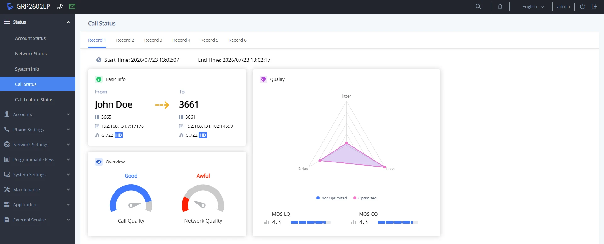
General Call Session Information | |
Start Time | Displays the exact timestamp when the call session was initiated. |
End Time | Displays the exact timestamp when the call session was terminated. |
Basic Info | |
From / To: | Displays caller ID details for both participants, including caller name, extension number, IP address with RTP port, and the negotiated audio codec (e.g., G.722 HD, Opus, PCMU). |
Overview | |
Call Quality | Provides an overall visual rating of the audio experience (e.g., Good, Great, Poor) based on real-time stream performance. |
Network Quality | Provides a visual rating reflecting the network conditions during the call. |
Quality | |
Quality Radar Chart | Displays a radar diagram evaluating three core voice metrics:
|
MOS-LQ | Displays the Mean Opinion Score Listening Quality, which measures estimated audio quality from the listener’s perspective on a scale from 1.0 to 5.0. |
MOS-CQ | Displays the Mean Opinion Score Conversational Quality, which measures total call quality, incorporating both listening clarity and mouth-to-ear delay effects. |
Call Feature Status
This page provides a centralized status summary and quick-access control panel for active call handling features, including Do Not Disturb (DND), Auto Answer, and Call Forwarding rules, across all configured SIP accounts.
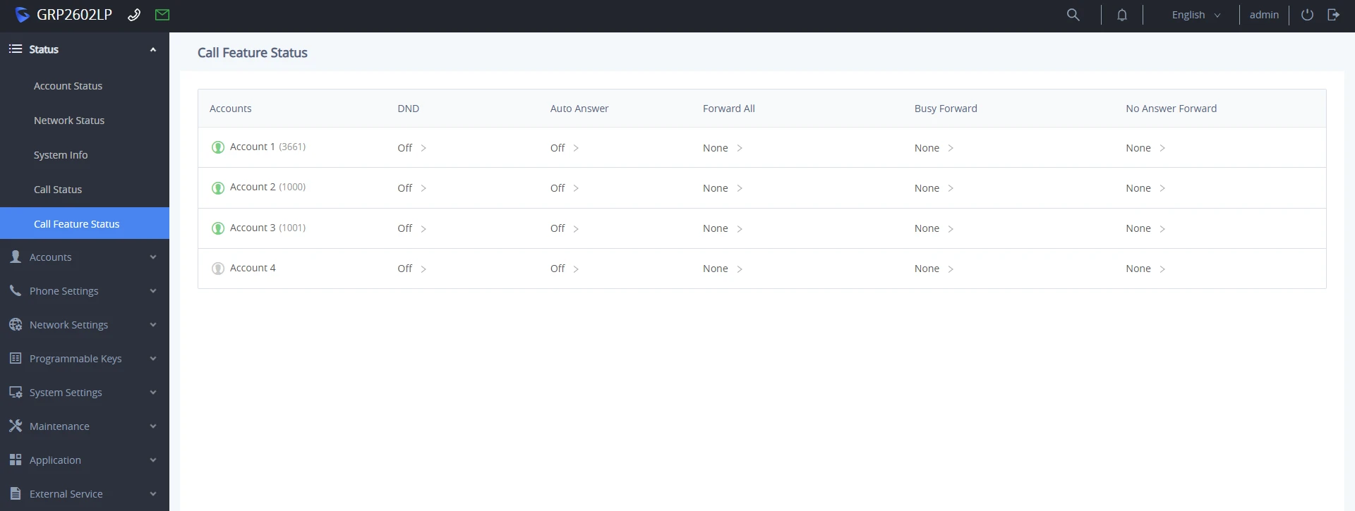
Accounts | Displays the account index, account name, extension number, and registration status icon (green icon for registered, grey icon for unregistered). |
DND | Displays whether Do Not Disturb is currently On or Off for the account. Clicking the arrow (>) redirects you directly to the configuration page to modify DND settings. |
Auto Answer | Displays the current Auto Answer status (On or Off) for the account. Clicking the arrow (>) redirects you to the configuration page for Auto Answer settings. |
Forward All | Displays the target destination number configured for unconditional call forwarding (Forward Always), or None if disabled. Clicking the arrow (>) redirects to the forwarding configuration page. |
Busy Forward | Displays the target destination number configured for Busy Call Forward, or None if disabled. Clicking the arrow (>) redirects to the corresponding configuration page. |
No Answer Forward | Displays the target destination number configured for Call Forward on No Answer, or None if disabled. Clicking the arrow (>) redirects to the corresponding configuration page. |
Accounts Page Definitions
Accounts
Account x → General Settings | |
Account Register | |
Account Active | Indicates whether the account is active. The default setting is “No”. |
Account Name | The name associated with each account. It will be displayed on the LCD. (e.g., MyCompany) |
SIP Server | The URL or IP address and port of the SIP server. This is provided by your VoIP service provider (e.g., sip.mycompany.com or an IP address) |
Secondary SIP Server | The URL or IP address and port of the SIP server. This will be used when the primary SIP server fails |
Tertiary SIP Server | The URL or IP address and port of the SIP server. This will be used when the primary and secondary SIP servers fail. |
Outbound Proxy | IP address or Domain name of the Primary Outbound Proxy, Media Gateway, or Session Border Controller. |
Secondary Outbound Proxy | Defines a secondary outbound proxy that will be used when the primary proxy cannot be connected. |
SIP User ID | User account information, provided by your VoIP service provider. |
SIP Authentication ID | SIP service subscriber’s Authenticate ID used for authentication. It can be identical to or different from the SIP User ID. |
SIP Authentication Password | The required account password for the phone to authenticate with the SIP server before the account can be registered. After it is saved, this will appear as hidden for security purposes. |
Name | The SIP server subscriber’s name (optional) that will be used for Caller ID display (e.g., John Doe). |
TEL URI | If the phone has an assigned PSTN telephone number, this field should be set to “user=phone”. A “user=phone” parameter will be attached to the Request-URI and “To” header in the SIP request to indicate the E.164 number. If set to “Enable”, “tel:” will be used instead of “sip:” in the SIP request. |
Voicemail Access Number | Allows users to access voice messages by pressing the MESSAGE button on the phone. This value is usually the VM portal access number. |
Monitored Voicemail Access Number | Configures the access code (e.g., *98) required to dial into the voicemail box of a monitored extension. When a Voicemail VPK/MPK is configured with a target extension, the device will use this access code followed by the target extension number (e.g., *981001) to access the monitored extension’s voicemail. |
BLF Server | Configures the BLF server (optional) used for SUBSCRIBE requests. |
Account Display | When set to “Username”, the LCD will display the Username if it is not empty and when set to “User ID”, the LCD will display the User ID if it is not empty. |
UCM User Password | Input UCM user login password to connect UCM user settings. |
Network Settings | |
DNS Mode | This parameter controls how the Search Appliance looks up IP addresses for hostnames. If “Use Configured IP” is selected, please fill in Primary IP, Backup IP 1 and Backup IP 2.
|
Max Number Of Sip Request Retries | Sets the maximum number of retries for the device to send requests to the server. In DNS SRV configuration, if the destination address does not respond, all request messages are resent to the same address according to the configured retry times. Valid range: 1-10. |
DNS SRV Failover Mode | Configures the preferred IP mode for DNS SRV.
If the option is set with “default”, it will again try to send register messages to one IP at a time, and the process repeats.
If the option is set with “Use current server until DNS TTL”, it will send register messages to the previously registered IP first. If no response, it will try to send one at a time for each IP. This behavior lasts if DNS TTL (time-to-live) is up.
If the option is set with “Use current server until no responses”, it will send registered messages to the previously registered IP first, but this behavior will persist until the registered server does not respond.
If “Use current server until failback timer expires” is selected, the device will send all SIP messages to the current failover SIP server or Outbound Proxy until the failback timer expires. |
Failback Expiration (m) | Specifies the duration (in minutes) since failover to the current SIP server or Outbound Proxy before making failback attempts to the primary SIP server or Outbound Proxy. |
Register Before DNS SRV Failover | Configures whether to send REGISTER requests to the failover SIP server or Outbound Proxy before sending INVITE requests in the event of a DNS SRV failover. |
Primary IP | Configures the primary IP address where the phone sends DNS query to when “Use Configured IP” is selected for DNS mode. |
Backup IP 1 | Configures the backup IP 1 address where the phone sends DNS query to when “Use Configured IP” is selected for DNS mode. |
Backup IP 2 | Configures the backup IP 2 address where the phone sends DNS query to when “Use Configured IP” is selected for DNS mode. |
NAT Traversal | Configures whether NAT traversal mechanism is activated. Please refer to user manual for more details. If set to “STUN” and STUN server is configured, the phone will route according to the STUN server. If NAT type is Full Cone, Restricted Cone or Port-Restricted Cone, the phone will try to use public IP addresses and port number in all the SIP&SDP messages. The phone will send empty SDP packet to the SIP server periodically to keep the NAT port open if it is configured to be “Keep-alive”. Configure this to be “No” if an outbound proxy is used. “STUN” cannot be used if the detected NAT is symmetric NAT. Set this to “VPN” if OpenVPN is used. |
Media NAT Traversal | Select the method of NAT traversal for media packets.
The default setting is “Auto”. |
Candidate Type | Note: This option appears when “ICE” is selected in the parameter Media NAT Traversal. Configure the ICE candidate type.
|
STUN/TURN Server | Fill in the STUN/TURN server related configurations. Note: This option appears when either ICE, STUN, or TURN is selected in the Media NAT Traversal parameter. |
Support rport (RFC3581) | Configures to use symmetric response routing. If it is used, the “rport” field |
Proxy-Require | A SIP Extension to notify the SIP server that the phone is behind a NAT/Firewall. |
Use SBC | Configures whether a SBC server is used. Note: If enabled, make sure an outbound proxy is set up. |
Account x → SIP Settings | |
Basic Settings | |
SIP Registration | Selects whether the phone will send SIP Register messages to the proxy/server. The default setting is “Enabled”. |
UNREGISTER on Reboot |
|
REGISTER Expiration | Specifies the frequency (in minutes) in which the phone refreshes its registration with the specified registrar. The maximum value is 64800 minutes (about 45 days). The default value is 60 minutes. |
SUBSCRIBE Expiration | Specifies the frequency (in minutes) in which the phone refreshes its subscription with the specified registrar. The maximum value is 64800 minutes (about 45 days). The default value is 60 minutes. |
Re-Register before Expiration | Specifies the time frequency (in seconds) that the phone sends re-registration request before the Register Expiration. The default value is 0. |
Registration Retry Wait Time | Specifies the interval to retry registration if the process is failed. The valid range is 1 to 3600. The default value is 20 seconds. |
Registration Retry Wait Time(s) upon 403 Forbidden | Specifies the interval to retry registration if the process is failed due to 403 Forbidden. Valid range is 0 to 3600 in second. 0 second means stop retry registration. Note: The default value is 1200 seconds |
Add Auth Header on Initial REGISTER | If enabled, the phone will add Authorization header in initial REGISTER request. Default is “Disabled”. |
Add Auth Header on RE-REGISTER | If enabled, the phone will add Authorization header in RE-REGISTER request. Note: This option is enabled by default. |
Enable OPTIONS Keep Alive | Configures whether to enable SIP OPTIONS to track account registration status. If enabled, the phone will send periodic OPTIONS messages to server to track the connection status with the server. Default is “Disabled”. |
OPTIONS Keep Alive Interval | Configures the time interval the phone sends OPTIONS message to the server. If set to 30 seconds, it means the phone will send an OPTIONS message to the server every 30 seconds. |
OPTIONS Keep Alive Max Retries | Configures the maximum number of times the phone will try to send OPTIONS message consistently to server without receiving a response. If set to “3”, the phone will send OPTIONS message 4 times. If no response from the server, the phone will re-register. |
SUBSCRIBE for MWI | When set to “Yes”, a SUBSCRIBE for Message Waiting Indication will be sent periodically. The default setting is “No”. |
SUBSCRIBE for Registration | When set to “Yes”, a SUBSCRIBE for Registration will be sent out periodically. The default setting is “No”. |
Use Privacy Header | Configures whether the “Privacy Header” is present in the SIP INVITE message.
The default setting is “default”. |
Use P-Preferred- Identity Header | Configures whether the “P-Preferred-Identity Header” is present in the SIP INVITE message.
|
Use X-Grandstream-PBX Header | Configures to use X-Grandstream-PBX header in SIP request. Default setting is “Yes”. |
Use P-Access-Network-Info Header | Configures to use P-Access-Network-Info header in SIP request. Default setting is “Yes”. |
Use P-Emergency-Info Header | Configures to use P-Emergency-Info header in SIP request. Default setting is “Yes”. |
Use P-Asserted-Identity Header | Configure whether the “P-Asserted-Identity Header” is present in the SIP REGISTER message. |
Use P-Early-Media Header | Configure if the “P-Early-Media Header” support is enabled. |
Use Zoom E911 X-switch-info SIP Header | Configure whether the “Zoom E911 X-switch-info SIP Header” is present in the SIP REGISTER message. |
Use MAC Header |
The default setting is “No”. |
Add MAC in User-Agent |
The default setting is “No”. |
SIP Transport | Selects the network protocol used for the SIP transport. The default setting is “UDP”. |
Enable TCP Keep-alive | Configures whether to enable TCP Keep-alive for the TCP connection between the terminal and the SIP server. |
SIP Listening Mode | Configures whether or not to listen to multiple SIP protocols.
The default setting is “Transport Only”. |
Local SIP Port | Configures the local SIP port used to listen and transmit. |
SIP URI Scheme when using TLS | Specifies whether “sip” or “sips” will be used when TLS/TCP is selected for SIP Transport. The default setting is “sips”. |
Use Actual Ephemeral Port in Contact with TCP/TLS | Configures whether the actual ephemeral port in contact with TCP/TLS will be used when TLS/TCP is selected for SIP Transport. The default setting is “No”. |
Support SIP Instance ID | Configures whether SIP Instance ID is supported or not. The default setting is “Yes”. |
SIP T1 Timeout | SIP T1 Timeout is an estimate of the round-trip time of transactions between a client and server. If no response is received, the timeout is increased, and request re-transmit retries continue until a maximum amount of time defined by T2. The default setting is 0.5 seconds. |
SIP T2 Timeout | SIP T2 Timeout is the maximum retransmit time of any SIP request messages (excluding the INVITE message). The retransmitting and doubling of T1 continues until it reaches the T2 value. The default is 4 seconds. |
Outbound Proxy Mode | Configures whether to put the Outbound Proxy in the Route header or if SIP messages should always be sent to the Outbound Proxy.
Default is “in route”. |
Enable 100rel | When enabled, the 100rel tag is appended to the value of the Supported header of the initial signaling messages. The default setting is “No”. |
Use Route Set in Notify (Follow RFC 6665) | Configures whether to use route set in NOTIFY (follow RFC6665).
|
Session Timer | |
Enable Session Timer | Configures whether to enable the session timer function. It enables SIP sessions to be periodically “refreshed” via a SIP request (UPDATE or re-INVITE). If there is no refresh via an UPDATE or re-INVITE message, the session will be terminated once the session interval expires. If set to “Yes”, the phone will use the related parameters when sending the session timer according to “Session Expiration”. If set to “No”, the session timer will be disabled. The default setting is “No”. |
Session Expiration | Session Expiration is the time (in seconds) at which the session is considered timed out, provided no successful session refresh transaction occurs beforehand. The default setting is 180. The valid range is from 90 to 64800. |
Min-SE | The minimum session expiration (in seconds). The default value is 90 seconds. The valid range is from 90 to 64800. |
Caller Request Timer | If set to “Yes” and the remote party supports session timers, the phone will use a session timer when it makes outbound calls. The default setting is “No”. |
Callee Request Timer | If set to “Yes” and the remote party supports session timers, the phone will use a session timer when it receives inbound calls. The default setting is “No”. |
Force Timer | If set to “Yes”, the phone will use the Session Timer even if the remote party does not support this feature. Otherwise, Session Timer is enabled only when the remote party supports it. The default setting is “No”. |
UAC Specify Refresher | As a caller, select UAC to use the phone as the refresher, or select UAS to use the callee or proxy server as the refresher. When set to “Omit”, the refresh object is not specified. The default setting is “UAC”. |
UAS Specify Refresher | As a callee, select UAC to use the caller or proxy server as the refresher, or select UAS to use the phone as the refresher. The default setting is “UAC”. |
Force INVITE | Select “Yes” to force the use of the INVITE method to refresh the session timer. The default setting is “No”. |
Account x → Codec Settings | |
Audio | |
Preferred Vocoder (Choice 1 – 8) | Multiple vocoder types are supported on the phone; the vocoders in the list are given higher preference. Users can configure vocoders in a preference list that is included with the same preference order in the SDP message. The vocoders supported are:
|
Codec Negotiation Priority | Configures the phone to use which codec sequence to negotiate as the callee. When set to “Caller”, the phone negotiates by SDP codec sequence from received SIP Invite. When set to “Callee”, the phone negotiates by audio codec sequence on the phone. The default setting is “Callee”. |
Use First Matching Vocoder in 200OK SDP | When set to “Yes”, the device will use the first matching vocoder in the received 200OK SDP as the codec. The default setting is “No”. |
iLBC Frame Size | Selects iLBC packet frame size. Users can choose from 20ms and 30ms. The default setting is “30ms”. |
iLBC Payload Type | Specifies iLBC payload type. Valid range is 96 to 127. Cannot be the same as Opus or DTMF payload type. Valid range is 96 to 127. The default setting is “97”. |
G.726-32 Packing Mode | Selects “ITU” or “IETF” for G.726-32 packing mode. The default setting is “ITU”. |
G.726-32 Dynamic Payload Type | Specifies G.726-32 payload type. Valid range is 96 to 127. Default is 127. |
Opus Payload Type | Specifies Opus payload type. Valid range is 96 to 127. It cannot be the same as iLBC or DTMF Payload Type. Default value is 123. |
Send DTMF | Specifies the mechanism to transmit DTMF digits. There are 3 supported modes:
Default setting is “RFC2833”. |
DTMF Payload Type | Configures the payload type for DTMF using RFC2833. Cannot be the same as iLBC or OPUS payload type. |
Inbound DTMF Volume | Sets the volume size when using in-audio DTMF transmission mode. The higher the parameter value, the higher the volume value. the valid range is 0-32. |
Enable Audio RED with FEC | If set to “Yes”, FEC will be enabled for audio call. |
Audio FEC Payload Type | Configures audio FEC payload type. The valid range is from 96 to 126. The default value is 121. |
Audio RED Payload Type | Configures audio RED payload type. The valid range is from 96 to 126. The default value is 124. |
Silence Suppression | If set to “Yes”, when silence is detected, a small quantity of VAD packets (instead of audio packets) will be sent during the period of no talking. For codec G.723 and G.729 only. Default setting is “No”. |
Jitter Buffer Type | Selects either Fixed or Adaptive for jitter buffer type, based on network conditions. The default setting is “Adaptive”. |
Jitter Buffer Length | Selects jitter buffer length from 100ms to 800ms, based on network conditions. The default setting is “300ms”. |
Voice Frames Per TX | Configures the number of voice frames transmitted per packet. It is recommended that the IS limit value of Ethernet packet is 1500 bytes or 120 kbps. When configuring this, it should be noted that the “ptime” value for the SDP will change with different configurations here. This value is related to the codec used in the codec table or negotiate the payload type during the actual call. For example, if set to 2 and the first code is G.729, G.711 or G.726, the “ptime” value in the SDP datagram of the INVITE request is 20 ms. If the “Voice Frame/TX” setting exceeds the maximum allowed value, the phone will use and save the maximum allowed value for the selected first codec. It is recommended to use the default setting provided, and incorrect setting may affect voice quality. The default setting is 2. |
G.723 Rate | Selects encoding rate for G723 codec. |
RTP Settings | |
SRTP Mode | Enable SRTP mode based on your selection from the drop-down menu.
The default setting is “No”. |
SRTP Key Exchange | Configures the key management protocol used to securely exchange encryption keys for SRTP media streams:
The default setting is “SDES”. |
SRTP Key Length | Allows users to specify the length of the SRTP calls. Available options are:
Default setting is AES 128&256 bit |
Crypto Life Time | Enable or disable the crypto lifetime when using SRTP. If users set to disable this option, phone does not add the crypto lifetime to the SRTP header. The default setting is “Yes”. |
RTCP Mode | Configure RTCP port negotiation rules.
|
RTCP Keep-Alive Method | Configures the RTCP channel keep-alive packet type.
|
RTP Keep-Alive Method | Configures the RTP channel keep-alive packet type.
|
VQ RTCP-XR Collector Address Selection | Configures the method for VQ RTCP-XR collector address selection. There are two supported methods:
The default setting for this parameter is “Manual”. |
VQ RTCP-XR Collector Name | Configure the host name of the central report collector that accepts voice quality reports contained in SIP PUBLISH messages. |
VQ RTCP-XR Collector Address | Configure the IP address of the central report collector that accepts voice quality reports contained in SIP PUBLISH messages. |
VQ RTCP-XR Collector Port | Configure the port of the central report collector that accepts voice quality reports contained in SIP PUBLISH messages. |
Symmetric RTP | Configures whether Symmetric RTP is used or not. Symmetric RTP means that the UA uses the same socket/port for sending and receiving the RTP stream. The default setting is “No”. |
RTP IP Filter | Configures strict source validation rules for incoming RTP audio packets to prevent unauthorized media injection:
The default setting is “Disable”. |
RTP Timeout (s) | Configures the RTP timeout of the phone. If the phone does not receive the RTP packet within the specified RTP time, the call will be automatically disconnected. The default range is 0 and 6-600. If set to 0, the phone will not hang up the call automatically. |
Account x → Call Settings | |
General | |
Key as Send | Allows users to configure either the “*” or “#” keys as the “Send” key. Please make sure the dial plan is properly configured to allow dialing * and # out. The default setting is “Pound (#)”. |
No Key Entry Timeout | Configures the timeout (in seconds) for no key entry. If no key is pressed after the timeout, the collected digits will be sent out. The default value is 4 seconds. The valid range is from 1 to 15. |
Send Anonymous | If set to “Yes”, the “From” header in outgoing INVITE messages will be set to anonymous. Default is “No”. |
Anonymous Call Rejection | If set to “Yes”, anonymous calls will be rejected. The default setting is “No”. |
Enable Call Waiting | Configures the call waiting function for this account. If set to “Default”, it will be configured according to global call waiting function. Default value is “Default”. |
RFC2543 Hold | Allows users to toggle between RFC2543 hold and RFC3261 hold. RFC2543 hold (0.0.0.0) allows user to disable the hold music sent to the other side. RFC3261 (a line) will play the hold music to the other side. The default setting is “No”. |
Ring Timeout | Configures the timeout (in seconds) for the phone to ring when an incoming call is not answered. Valid range is 30 to 3600. The default setting is 60. |
Call Log | Configures Call Log setting on the phone.
The default setting is “Log All Calls”. |
Auto Answer | |
Auto Answer | If set to “Yes”, the phone will automatically turn on the speaker phone to answer incoming calls after a short reminding beep. Default setting is “No”. |
Auto Answer Numbers | Allows the user to configure specific numbers to auto answer. If not set, all numbers will be auto answered If auto answer is enabled. Up to 10 numbers can be configured. |
Intercom | |
Play warning tone for Auto Answer Intercom | If enabled, phone will play warning tone when auto answering Intercom. |
Custom Alert-Info for Auto Answer | Used exclusively to match the contents of the Alert-Info header for auto answer. The default auto answer headers will not be matched if this is defined. |
Allow Auto Answer by Call-Info/Alert-Info | If set to “Yes”, the phone will automatically turn on the speaker phone to answer incoming calls after a short reminding beep, based on the SIP Call-Info/Alert-Info header sent from the server/proxy. Default is “Yes”. |
Allow Barging by Call-Info/Alert-Info | When enabled, the phone will automatically put the current call on hold and answer the incoming call based on the SIP Call-Info/Alert-Info header sent from the server/proxy. However, if the current call was answered based on the SIP Call-Info/Alert-Info header, then all other incoming calls with SIP Call-Info/Alert-Info headers will be rejected automatically. Default setting is “No”. |
Mute on Intercom Answer | If enabled, the phone will mute the mirophone after answer an intercom call via Call-Info/Alert-Info. |
Record | |
Record Key Default Fuction | Configures whether to turn the recording function on or off when the “Record” key is pressed for the first time in a call using this account. For example, the SIP server can be configured with automatic call recording. In this case, Record key default function should be configured as “Record off”. |
Call Recording On | Configures the DTMF sequence sent when pressing the Record key during a call on this account. Toggles between this value and the off code if possible; otherwise always sends this code. |
Call Recording Off | Configures the DTMF sequence sent when pressing the Recording key during a call on this account when turning recording off. |
Transfer | |
Transfer on Conference Hangup | Configures whether the call is transferred to the other party if the conference initiator hangs up. The default setting is “No”. |
Transfer to VM feature code | During a call, press the transfer to voicemail softkey or voicemail hard button, enter the extension number, and then transfer the call to the extension voicemail by entering the transfer to VM feature code defined. At this point, the code will be used as an extension prefix and called into the SIP server to complete the transfer to voicemail event. |
Enable Recovery on Blind Transfer | Enable recovery to the call to the transferee on failing blind transfer to the target. The default setting is “Yes”. Notes:
|
Blind Transfer Wait Timeout | Configures the timeout (in seconds) when waiting for sipfrag response in blind transfer. Valid range is 30 to 300. Default setting is “30”. |
Refer-To Use Target Contact | If set to “Yes”, the “Refer-To” header uses the transferred target’s Contact header information for attended transfer. |
Call Forward | |
Enable Forward All | If set to “Yes”, all calls will be forwarded to the number specified below. Disabled by Default |
All To | Specifies the number to be forwarded to when enabled Forward all. |
Enable Busy Forward | If set to “Yes”, the call will be forwarded to the number specified below on busy. Disabled by Default |
Busy To | Specifies the number to be forwarded to for Call Forward On Busy. |
Enable No Answer Forward | If set to “Yes”, the call will be forwarded to the number specified below on no answer. Disabled by Default |
No Answer To | Specifies the number to be forwarded to for Call Forward On No Answer. |
No Answer Timeout (s) | Defines the timeout (in seconds) before the call is forwarded on no answer. |
Enable Override Forward | If enabled, the local call forward is disabled when an incoming call comes in from the configured override forward number. Disabled by Default |
Override Forward Numbers | Configures the number to override the local forward function. The Max number is 10. |
Dial Plan | |
Dial Plan Prefix | Configures a prefix added to all numbers when making outbound calls. |
Bypass Dial Plan | Bypass the dial plan when dialing from one of the available items:
|
Dial Plan | Configures the dial plan rule. For syntax and examples, please refer to the user manual for more details. Dial Plan Rules:
Allow 311, 611, and 911 or any 11-digit numbers with leading digits 1617;
Block any number of leading digits 1900 or add prefix 1617 for any dialed 7-digit numbers;
Allows any number with leading digit 1 followed by a 3-digit number, followed by any number between 2 and 9, followed by any 7-digit number OR allows any length of numbers with leading digit 2, replacing the 2 with 011 when dialed.
Allows any number starting with any digit from “0-9” followed by a hyphen “-” and any character from “0-9, a-z, A-Z” then an asterisk “*”.
Explanation of example rule (reading from left to right):
Note: In some cases, where the user wishes to dial strings such as *123 to activate voicemail or other applications provided by their service provider, the * should be predefined inside the dial plan feature. An example dial plan will be: { *x+ } which allows the user to dial * followed by any length of numbers. Max length of a dial plan is up to 1024 characters.
|
Call Display | |
Caller ID Display | When set to “Auto”, the phone will look for the caller ID in the order of the P-Asserted Identity Header, Remote-Party-ID Header, and From Header in the incoming SIP INVITE. When set to “Disabled”, all incoming calls are displayed with “Unavailable”. |
Callee ID Display | When set to “Auto”, the phone will update the callee ID in the order of the P-Asserted Identity Header, Remote-Party-ID Header, and To Header in the 180 Ringing. When set to “Disabled”, the callee ID will be displayed as “Unavailable”. When set to “To Header”, caller ID will not be updated and will be displayed as To Header. |
Ringtone | |
Ringback Tone at No Early Media | Play ringback tone when there are no received early media RTP packets. Disabled by Default |
Account RingTone | Allows users to configure the ringtone for the account. Users can choose from different ringtones from the dropdown menu. Note: User can also choose silent ring tone or doorbell. |
Ignore Alert-Info header | Configures to play default ringtone by ignoring Alert-Info header. The default setting is “No”. |
Enable Alert-Info Bellcore Mapping | This feature allows the IP phone to enable or disable the mapping of keywords in the Alert-Info header to predefined Bellcore ring tones. When an Alert-Info header containing “Bellcore-dr%N” is received—where N is a value between 1 and 5—the corresponding Bellcore ring tone will be played if the option is enabled. If the option is disabled, a corresponding custom ring tone will be played instead. When N is 0, a silent ringtone will be used. When N is 6, a corresponding custom ringtone will always be played, regardless of the option setting. If N is outside the valid range (i.e., less than 0 or greater than 6), the default ring tone will be used. Note: This option is enabled by default. |
Match Incoming Caller ID | Specifies matching rules with a number, pattern, or Alert Info text (up to 10 matching rules). When the incoming caller ID or Alert Info matches the rule, the phone will ring with the selected distinctive ringtone. Matching rules:
xx+ : at least a 2-digit number. xx : only a 2-digit number. [345]xx: 3-digit number with the leading digit of 3, 4, or 5. [6-9]xx: 3-digit number with the leading digit from 6 to 9.
Users could configure the matching rule as certain text (e.g., priority) and select the custom ringtone mapped to it. The custom ringtone will be used if the phone receives a SIP INVITE with an Alert-Info header in the following format: Alert-Info: <http://127.0.0.1>; info=priority. When the incoming caller ID or Alert Info matches one of the 10 rules, the phone will ring with the associated ringtone. |
Account x → Advanced Settings | |
Security Settings | |
Check Domain Certificates | Configures whether the domain certificates will be checked when TLS/TCP is used for SIP Transport. The default setting is “No”. |
Trusted Domain Name List | Configure the list of trusted domain names, which supports filling in the SAN list used only for domain name verification in TLS to obtain certificates. If it matches any item in the trusted domain name list, the certificate is trusted. By default, the remote proxy domain name and SIP server domain name are trusted. This field allows numbers/letters/-/./*. It supports wildcard domain names, such as “*.mycompany.com“, and trusts any domains ending with “.mycompany.com“. |
Validate Certificate Chain | Validate the certification chain when TCP/TLS is configured. The default setting is “No”. |
Validate Incoming SIP Messages | Specifies whether the phone will check the incoming SIP messages’ Caller ID and CSeq headers. If the message does not include the headers, it will be rejected. The default setting is “No”. |
Omit charset=UTF-8 in MESSAGE | Omit charset=UTF-8 in MESSAGE content-type |
Allow Unsolicited REFER | Configures whether to dial the number carried by the Refer-to header after receiving an out-of-dialog SIP REFER request actively. If set to “Disabled“, the phone will send an error warning and stop dialing. If set to “Enabled/Force Auth“, the phone will dial the number after sending authentication. If the authentication fails, it will stop dialing. If set to “Enabled“, the phone will dial all numbers carried by SIP REFER. |
Accept Incoming SIP from Proxy Only | When set to “Yes”, the SIP address of the Request URL in the incoming SIP message will be checked. If it does not match the SIP server address of the account, the call will be rejected. The default setting is “No”. |
Check SIP User ID for Incoming INVITE | If set to “Yes”, SIP User ID will be checked in the Request URI of the incoming INVITE. If it does not match the phone’s SIP User ID, the call will be rejected. The default setting is “No”. |
Allow SIP Reset | Allow SIP Notification message to perform factory reset. The default setting is “No”. |
Authenticate Incoming INVITE | If set to “Yes”, the phone will challenge the incoming INVITE for authentication with a SIP 401 Unauthorized response. The default setting is “No”. |
MOH | |
On Hold Reminder Tone | Configures to play reminder tone when the call is on hold. |
Music On Hold URI | Music On Hold URI to call when a call is on hold if the server supports it. |
Advanced Features | |
Special Feature | Different soft switch vendors have special requirements. Therefore, users may need to select special features to meet these requirements. Users can choose from Standard, Nortel MCS, Broadsoft, CBCOM, RNK, Sylantro, Huawei IMS, Zoom, PhonePower, and UCM Call Center depending on the server type. The default setting is “Standard”. |
Feature Key Synchronization | This feature is used for Broadsoft call feature synchronization. When it is enabled, DND, Call Forward features, and Call Center Agent status can be synchronized between the Broadsoft server and the phone. The default is “Disabled”. |
Conference URI | Configures the conference URI when using Broadsoft N-way calling feature. |
Reboot on check-sync event without “reboot=” | If option is enabled, the phone will do reboot when receiving SIP NOTIFY check-sync event without “reboot=” header. If the option is disabled, the phone will do provision and not reboot when receiving SIP NOTIFY check-sync event without “reboot=” header. Note: This option is disabled by default. |
BroadSoft Call Center | When Special Features is set to BroadSoft, enables Feature Key Synchronization regardless of web UI settings. Default is Disabled. |
Hoteling Event | When Special Features is set to BroadSoft, enables the Hoteling Event feature. Disabled by default. |
Call Center Status | When Special Features is set to BroadSoft, enables the Call Center Status feature. The phone sends a SUBSCRIBE request to the server to retrieve call center status. Disabled by default. |
BroadSoft Executive Assistant | When Special Features is set to BroadSoft, enables the Executive Assistant feature. Disabled by default. |
BroadSoft Call Park | When Special Features is set to BroadSoft, enables the BroadSoft Call Park feature. The phone sends a SUBSCRIBE request to the BroadSoft server to receive Call Park notifications. Disabled by default. |
Enable Call Monitor Function | When Special Features is set to Zoom, enables the Call Monitor function. Enbaled by default. |
Support Call Monitor Privacy Mode | When Special Features is set to Zoom, enables privacy mode for Call Monitor. This mode can be toggled on or off directly from the phone’s LCD. Enabled by default. |
Barge-in Feature Code | When Special Features is set to Zoom, specifies the feature code used for barge-in (e.g., *123). |
Listen Feature Code | When Special Features is set to Zoom, specifies the feature code used to silently monitor an active call. |
Whisper Feature Code | When Special Features is set to Zoom, specifies the feature code used to whisper during a monitored call, allowing private guidance without being audible to the other call participants. |
Takeover Feature Code | When Special Features is set to Zoom, specifies the feature code used to take over an active monitored call. |
BLF (Busy Lamp Field) *GRP2602LP/GRP2602LG Only | |
Presence Eventlist URI | Configures Presence Eventlist URI to monitor the extensions on Multi-Purpose Keys. |
Eventlist BLF URI | Configures Eventlist BLF URI to monitor the extensions on Multi-Purpose Keys |
Auto provision Eventlist | Select the type of Eventlist to get automatically provisioned onto available MPKs. Whether it’s BLF Eventlist or Presence Eventlist. |
BLF Call-pickup | Configures BLF Call-pickup method:
The phone will do either a prefix or a barge-in code for BLF pickup, depending on which one is set.
The phone will ignore both BLF pickup methods; now the monitored VPK will only dial the extension if pressed
The phone will ignore both BLF pickup methods; now the monitored VPK will only dial the extension if pressed. |
BLF Call-pickup Prefix | Configures the prefix prepended to the BLF extension when the phone picks up a call with the BLF key. The default setting is **. |
Call Pickup Barge-In Code | Configures the feature access code of Call Pickup with the Barge-in feature. |
PUBLISH for Presence | Enables presence feature on the phone. The default setting is “No”. |
SCA | |
Line-Seize Timeout | Configures the interval (in seconds) when the line-seize is considered timed out when the Shared Call Appearance feature is used. The valid range is 15 to 60. |
Call Park | |
Call Park Feature Code | Configure the feature access code for parking the current call to the parking lot or another extension. |
Call Park Retrieve Feature Code | Configure the feature access code for retrieving the parked call on accounts or BLF keys. |
Account x → Dial Plan | |
Name | Enter the name for the configured rules. |
Rule | Enter the rule settings (number pattern, prefix to add …etc.). |
Type | Choose the type of the rule:
|
Account x → Hidden Number Plan | |
Hidden Number Feature | If set to “Yes”, the incoming and outgoing number display will be handled according to the hidden number plan. |
Hidden Number Plan List | Currently, the incoming and outgoing number display will be handled according to the hidden number plan. Users can configure the hidden number rules, matching their syntax rules from top to bottom as follows:
Examples x+(xxxx)xxxx: 13705806547 -> 137****6547 xxx(x+)xxxx: 07113705806547 -> 071*******6547 071-x+(xxxx)xxxx: 071-13705806547 -> 071-137****6547 |
Hidden Number Plan Test | Enter the number to test the hidden rules of the current page. After confirming, please save and apply it. |
Account x → Feature Codes | |
Local Call Features Mode | Configures whether call features are handled locally on the phone using user feature codes or through feature codes provisioned by the server. This setting affects how features such as Do Not Disturb (DND) and Call Forwarding are executed.
Note: If the device is registered with a Broadsoft account, it does not matter if local call features are enabled or disabled. Once the Broadsoft account is set up, special feature to Broadsoft and Feature Key Synchronization is enabled, the call feature will be handled by the Broadsoft server, not by the phone. |
DND | |
DND Call Feature On | Configures DND feature code to turn on DND. |
DND Call Feature Off | Configures DND feature code to turn off DND. |
Call Forward Always | |
On | Configures Call Forward Always feature code to activate unconditional call forwarding. |
Off | Configures the Call Forward Always feature code to deactivate unconditional call forwarding. |
Target | The extension the call will be forwarded to. |
Call Forward No Answer | |
On | Configures the feature code to activate busy call forwarding. |
Off | Configures the feature code to disable busy call forwarding. |
Target | The extension the call will be forwarded to. |
Call Forward No Answer | |
On | Configures the Call Forward No Answer feature code to activate no-answer call forwarding. |
Off | Configures the Call Forward No Answer feature code to deactivate no-answer call forwarding. |
Target | The extension the call will be forwarded to. |
Call Forward No Answer Timeout (s) | Defines the timeout (in seconds) before the call is forwarded on no answer. valid range is 1 to 120. |
Account Swap
The Account Swap page allows administrators to quickly exchange configuration settings between two SIP accounts on the phone. This eliminates the need to manually re-enter credentials, server addresses, and line preferences when swapping account positions.
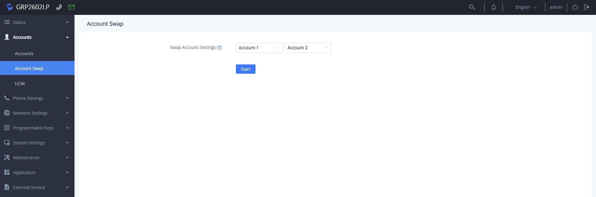
Swap Account Settings | Select two configured SIP accounts from the drop-down menus to swap their account positions and configuration parameters. |
Start | Click the button to initiate the account swapping process. The phone will swap the registration settings and line key mappings between the two selected accounts. |
UCM
Enables users and administrators to log into the UCM User Portal directly through the phone’s Web UI for a specific SIP account.
Account Tabs | Select the target SIP account tab corresponding to the extension registered on the UCM IP-PBX. |
Extension | Displays the extension number associated with the selected SIP account |
UCM Password | Enter the user portal login password assigned to the corresponding extension on the UCM IP-PBX. |
Verification Code | Enter the CAPTCHA characters displayed in the adjacent image box to authenticate the login attempt and prevent automated logins. |
Login | Click the button to initiate authentication with the UCM server. |
Phone Settings Page Definitions
General Settings
Phone Settings → General settings | |
Basic Settings | |
Local RTP Port | This parameter defines the local RTP port used to listen and transmit. It is the base RTP port for channel 0. When configured, channel 0 will use this port _value for RTP; channel 1 will use port_value+2 for RTP. Local RTP port ranges from 1024 to 65400 and must be even. The default value is 5004. |
Local RTP Port Range | Gives users the ability to define the parameter of the local RTP port used to listen and transmit. This parameter defines the local RTP port from 48 to 10000. This range will be adjusted if local RTP port + local RTP port range is greater than 65486. Default setting is 200. |
Use Random Port | When set to “Yes”, this parameter will force random generation of both the local SIP and RTP ports. This is usually necessary when multiple phones are behind the same full cone NAT. The default setting is “Yes” Note: This parameter must be set to “No” for Direct IP Calling to work. |
Keep-alive Interval | Specifies how often the phone sends a blank UDP packet to the SIP server to keep the “ping hole” on the NAT router to open. The default setting is 20 seconds. The valid range is from 10 to 160. |
STUN Server | The IP address or Domain name of the STUN server. STUN resolution results are displayed in the STATUS page of the Web GUI. Only non-symmetric NAT routers work with STUN. |
Use NAT IP | The NAT IP address used in SIP/SDP messages. This field is blank at the default settings. It should ONLY be used if it is required by your ITSP. |
Delay Registration | Configures specific time that the account will be registered after booting up. |
Enable Outbound Notification | Configures whether to enable outbound notifications such as Action URL. |
Clean User Data When Different Users Log In | When enabled, if the current login account is different with last one, Device under tesr will delete the contact and call history of the last account. |
Public Mode | |
Enable Public Mode | Configures to turn on/off public mode for hot desking feature. |
Public Mode Username Prefix | Configures the prefix of the username for public mode login. |
Public Mode Username Suffix | Configures the suffix of the username for public mode login. |
Allow Multiple Accounts | Configures remaining account with a SIP account and be able to make/receive calls on the configured account even if the user is not logged in to the public mode. – If set to “No”, then after the user logs in to the public mode account on LCD, only the public mode account can be used on the phone even though there are other configured SIP accounts. – If set to “Yes,” then after the user logs in to the public mode account on LCD, other configured SIP accounts on the phone can also be used. Note: Note: This option requires enabling public mode to take effect. |
Enable Remote Synchronization | If enabled, the phone will automatically download the current account’s settings from the remote server and upload it to the server. |
Server Type | Configures the Server type and protocol used to send requests to the Remote Synchronization Server. This can be set to TFTP, FTP, HTTP |
Server Path | Configures the server path for the Remote Synchronization feature. |
FTP/HTTP Username | The username for FTP/HTTP server. |
FTP/HTTP Password | The password for FTP/HTTP server. |
Public Mode Timeout | Sets the public mode timeout (min), the time starts from the last idle state of the phone. The Default value is 10min |
Pop-up Hidden Settings | |
Hide Pop-up Options | Configures filtering rules to prevent specific screen pop-up notifications from appearing on the phone’s LCD display:
|
Custom Mode | When Hide Pop-up Options is set to Custom, administrators can use the Custom Mode selection tree to granularly select specific pop-up notifications to hide on the phone’s LCD display |
Call Settings
Phone Settings → Call Settings | |
General | |
Key Mode | Account Mode In Calling State, each key displays the call status of the corresponding account. Click to switch to the first line under this account or select the account to initiate a new call. Line Mode In Calling State, each key controls a line, and the call line can be switched by pressing the key. |
Preferred Default Account | Select the preferred default account for on-hook or off-hook dialing. When the selected account is unavailable, system will use the first available account to dial out. |
Mute Key Functions While Idle | Select “Mute” key function while the phone is idle.
|
Last Call Froward Always | If enabled, the number put into the ForwardAll feature will be stored the next time you use the ForwardAll softkey. |
Show SIP Error Response | Configures to enable SIP error response information displayed on the LCD screen. |
Escape ‘#’ as %23 in SIP URI | Replaces # by %23 for some special situations. |
User-Agent Prefix | Configures the prefix in the User-Agent header. |
Call-ID Domain Mode | Configure the Call-ID domain format.

 Note: The default setting is Masked Info. |
Enable Hook Switch | When set to “No”, disable hook switch completely; When set to “Yes, except answering call”, hook switch cannot be used for answering call. |
Enable Speaker Key | Sets whether to enable the speaker key.
|
Voicemail Key Mode | Enables/disables the voicemail key.
|
In-call Contact Info Display | Configures custom contact details to display on screen during an active call (up to 5 lines). The supported tags are:
Note: On smaller screens, the display will automatically scroll vertically to show all configured lines. |
Contact Source Priority | Configure the priority if the ID source displayed on the phone when incming/outgoing calls. Select on ID source and click Up/Down arrow on the right to adjust the order. |
Outgoing | |
Click-To-Dial Feature | Enables Click-To-Dial feature. If this feature is enabled, user could click the green dial button on left top corner of phone’s Web GUI, then choose the account and dial to the target number. The default setting is “Disabled”. This options is disabled by default. |
Enable Direct IP Call | Enables the Direct IP Call feature. This option is enabled by default but will be disabled after a factory reset. |
Use Quick IP Call Mode | When set to “Yes”, users can dial an IP address under the same LAN/VPN segment by entering the last octet of the IP address. This options is disabled by default. |
Enable Paging Call Mode | Configures enable/disable paging call mode of the phone. If set to “Yes”, the feature of paging call will be enabled. Default is Yes. |
Predictive Dialing Feature | Configures the predictive dialing feature on the call screen. |
Predictive Dialing Source | Predictive dialing feature will sequentially search the number based on the selected sources. |
Enable Local Dialing DTMF Tone in Speaker Mode | Configures whether to play local DTMF tone during dialing when using speaker, if enabled, you can set it play normal DTMF, or a single specific tone |
Onhook Dial Barging | When the option is set to “Disabled”, onhook dialing won’t be interrupted by an incoming call. |
Off-hook Auto Dial | Configures the digits to be dialed via the first account when the phone is off-hook. |
Off-hook Auto Dial Delay | Configures the digits to be dialed via the first account when the phone is off-hook. |
Off-hook/On-hook Timeout (s) | If configured, when the phone is in the off-hook or on-hook dialing state, it will go idle after the timeout (in seconds). Valid range is 10 to 60. |
Enable Live Keypad | If enabled, phone will automatically dial out and turn on hands-free mode when keypad or softkey is pressed. |
Live Keypad Expiration | Configures the expiration time for live keypad. Interval is between 2s and 15s. Default value is 5s. |
Enable Auto Redial | Configures to redial automatically at a later time when the dialed number is currently busy. |
Auto Redial Times | Configures the total times to redial if “Auto Redial” is enabled. |
Auto Redial Interval | Configures the interval between each redial if “Auto Redial” is enabled. |
Bypass Dial Plan Through Call History and Directories | Configures hether to check dial plan when dialing from call history and phonebook directories. |
Enable Call Completion Service | If enabled, phone will automatically redial the previous failed call when the remote party becomes available. |
Incoming | |
Enable Incoming Call Popup | If set to “Yes”, phone will pop up an incoming call window to notify the call. |
Enable Missed Call Notification | If set to “Yes”, phone will show a prompt about the missed call information. |
Return Code When Refusing Incoming Call | Configures the return code that phone will send to the call when it refuses an incoming call. |
Allow Incoming Call before Ringing | This allows incoming calls after dialed but before ringing. This can be used under custom user configuration based on need. |
Enable Call Waiting | Disables the call waiting feature. The default setting is “Yes”. |
Enable Call Waiting Tone | Enables Call Waiting alert tone when another incoming call is received while a call is in progress. The default setting is “Yes”. |
Ring for Call Waiting | Configures the phone to ring instead of playing call waiting tone when handset or headset is used. |
Auto Answer Delay | Configures the delay for automatically answering the incoming call. Valid range is 0 to 10 (seconds) |
In Call | |
Enable In-call DTMF Display | When set to “No”, the DTMF digits entered during a call will not be displayed on LCD. |
Enable Local In-call DTMF Tone in Speaker Mode | Allows users to enable/disable hearing DTMF tones locally through the device’s speaker during a call when in speaker mode. |
Enable Sending DTMF via specific MPKs | Allows certain MPKs to send DTMF in-call. This option does not affect Dial DTMF. |
Show on Hold Duration | Shows the duration of holding a call on the LCD |
Enable Auto Unmute | If the option is enabled, automatically unmute the phone when a user unholds the call or establishes a new call. |
In-call Dial Number on Pressing Transfer Key | Configures the number to be dialed as DTMF using TRANSFER button. |
Enable Busy Tone on Remote Disconnect | Configures the phone to Play busy tone when call is disconnected remotely. |
Enable Mute Key In Call | When set to “No”, the mute key will not work while on call. |
Phonebook Matching | |
Filter Characters | Defines separator characters to automatically strip from numbers during call placement (e.g., for imported contacts or Click2Dial). This applies to calls from Click2Dial, Call History, and Contacts and does not include direct entry on the dialing screen. Example: If set to [()-], calling (0571)-8800-8888 automatically dials 057188008888. |
Enable Phonebook Matching Rules | Enables rule-based number processing for contact matching:
|
Phonebook Matching Rules | Configures pattern-matching and replacement rules to transform dialed phone numbers so they match saved contact entries correctly. Rules are evaluated sequentially from top to bottom.
Rule Examples:
|
Phonebook Matching Rules Test | Allows testing of configured rules. Enter a number in Number and click >> to view the transformed result in Test result. |
Others | |
Transfer | |
Enable Transfer | Enables Call Transfer feature. |
Hold Call Before Completing Transfer | When set to “No”, the phone will not hold the current call or the transfer target for an Attended Transfer. |
Attended Transfer Mode |
|
Call Park | |
Enable Call Park Softkey | Enable call park service to use call park related softkeys. |
Call Park Softkey Feature Code | Configure the feature access code for parking current call to parking lot or another extension. |
Group Call Park Softkey Feature Code | Configure the feature access code for parking current call to the group current user is in. |
Call Park Retrieve Softkey Feature Code | Configure the feature access code for retrieving the parked call on accounts or parking lot. |
DND | |
Enable DND Feature | If enabled, the Do Not Disturb feature can be activated via MUTE key, MPK, or using the menu on LCD. |
Return Code Upon DND | Configures the return code that phone will send when it has DND enabled. |
Override DND | Configures to override the local DND function.
Note: The default setting is Off. |
Override DND Numbers | Configure the number to override the local DND function. |
Conference | |
Enable Conference | Enables the conference feature. |
Hold Call Before Conferee | Configures whether to put the current call on hold while adding new members to a conference. If set to “Yes”, the current call will be put on hold when the host presses conference or add key to invite new members. When the invited member answers the call and agrees to attend the conference, the host needs to manually resume the conference with the new member added. If set to “No”, the current call will not be put on hold and the invited member will join the meeting automatically after answering the call. |
BLF | |
Enable BLF Pickup Screen | Configures to show a softkey which leads to a monitor screen when a monitoring BLF line is ringing. |
Enable BLF Pickup Sound | Configures to play sound when a monitoring BLF line is ringing. |
Hide BLF Remote Status | Configures to hide the status information of the monitored line. |
IM | |
Enable IM Popup | If enabled, the phone will show a pop up upon receiving an IM. |
Instant Message Popup Timeout | Configures the number of seconds that the message will remain on screen. |
Play Tone on Receiving IM | Configures to play a short tone when phone receives an IM during idle state. |
Record | |
Enable the Indicator in Recording | When the call is recorded, the recording indicator is displayed on the LCD. |
Ringtone
Phone settings → Ringtone | |
Call Progresses Tones:
| Configures ring or tone frequencies based on parameters from local telecom. The default value is the North American standard. Frequencies should be configured with known values to avoid uncomfortable high-pitched sounds. Syntax: f1=val,f2=val[,c=on1/off1[-on2/off2[-on3/off3]]]; ON is the period of ringing (“On time” in ‘ms’) while OFF is the period of silence. To set a continuous ring, OFF should be zero. Otherwise, it will ring ON ms and a pause of OFF ms and then repeat the pattern. Up to three cadences are supported. Call Waiting tone gain can be set to either: Low, Medium, or High, it is set to Low by Default Auto-Answer Tone Gain can be set to either: Low, Medium, or High, Set to Medium by Default |
Provision | |
Total Number of Custom Ringtone Update | Configures the number of custom ringtones to update in the provisioning process. Default Value is 6. |
Multicast Paging
Phone settings → Multicast Paging | |
Multicast Paging Function | Enable or disable multicast paging |
Allowed In DND Mode | Allow Multicast Paging when DND mode is enabled. Default Setting is “No”. |
Paging Barge | During active call, if incoming multicast page is higher priority (1 being the highest) than this value, the call will be held, and multicast page will be played. The default setting is “Disabled”. |
Paging Priority Active | If enabled, during a multicast page if another multicast is received with higher priority (1 being the highest) that one will be played instead. The default setting is “Enabled”. |
Multicast Channel Number | Multicast Channel Number (0-50). 0 for normal RTP packets, 1-50 for Polycom multicast format packets. |
Multicast Paging Codec | The codec for sending multicast pages, there are 5 codecs could be used: G.731.1 PCMU, PCMA, G.726-32, G.729A/B, G.722 (wide band). Default setting is “PCMU”. |
Multicast Sender ID | Outgoing caller ID that displays to your page group recipients (for multicast channel 1 – 50). |
Multicast Call Timeout (s) | Set multicast based call timeout. When the multicast call exceeds the set time, it will automatically hang up and set to 0 without timeout. |
Multicast Tone | If enabled, there will be a prompt sound at the beginning and end of the receiver’s multicast intercom. The default setting is enabled. |
Multicast Listening | Defines multicast listening addresses and labels. For example:
For details, please check the “Multicast Paging User Guide” on our Website. |
Network Settings Page Definitions
Ethernet Settings
Network Settings → Ethernet Settings | |
Internet Protocol | Select “IPv4 Only”, “IPv6 Only”, “Both, prefer IPv4” or “Both, prefer IPv6”. The default setting is “IPv4 only”. |
IPv4 Address | |
IPv4 Address | Allows users to configure the appropriate network settings on the phone to obtain an IPv4 address. Users can select “DHCP” or “Static IP”. By default, it is set to “DHCP”. |
Host name (Option 12) | Specifies the name of the client. This field is optional but may be required by Internet Service Providers. |
Vendor Class ID (Option 60) | Used by clients and servers to exchange vendor class ID. |
IPv4 Address | Enter the IP address when static IP is used. |
Subnet Mask | Enter the Subnet Mask when static IP is used for IPv4. |
Gateway | Enter the Default Gateway when static IP is used for IPv4. |
DNS Server 1 | Enter the DNS Server 1 when static IP is used for IPv4. |
DNS Server 2 | Enter the DNS Server 2 when static IP is used for IPv4. |
Preferred DNS Server | Enters the Preferred DNS Server for IPv4. |
IPv6 Address | |
IPv6 Address Type | Allows users to configure the appropriate network settings on the phone to obtain IPv6 address. Users could select “Auto-configured” or “Statically configured” for the IPv6 address type. |
Static IPv6 Address | Enter the static IPv6 address when Full Static is used in “Statically configured” IPv6 address type. |
IPv6 Prefix Length | Enter the IPv6 prefix length when Full Static is used in “Statically configured” IPv6 address type. |
IPv6 Prefix(64 bits) | Enter the IPv6 Prefix (64 bits) when Prefix Static is used in “Statically configured” IPv6 address type. |
DNS Server 1 | Enter the DNS Server 1 for IPv6. |
DNS Server 2 | Enter the DNS Server 2 for IPv6. |
Preferred DNS server | Enter the Preferred DNS Server for IPv6. |
802.1X | |
802.1X mode | Allows the user to enable/disable 802.1X mode on the phone. The default value is disabled. To enable 802.1X mode, this field should be set to EAP-MD5, users may also choose EAP-TLS, or EAP-PEAPv0/MSCHAPv2. |
802.1X Identity | Enter the Identity information for the 802.1x mode. Note: Letters, digits and special characters including @ and – are accepted. |
MD5 Password | Enter the MD5 Password for the 802.1X mode. Note: Letters, digits and special characters including @ and – are accepted. |
802.1X CA Certificate | Uploads / deletes the 802.1X CA certificate to the phone; or delete existed 802.1X CA certificate from the phone. |
802.1X Client Certificate | Uploads / deletes the 802.1X CA certificate to the phone; or delete existed 802.1X CA certificate from the phone. |
Wi-Fi Settings
Network Settings → Wi-Fi Settings (GRP2601LW Only) | |
Wi-Fi Function | Enables / Disables the Wi-Fi on the phone. Three options are available:
|
Wi-Fi Band | Set the type of Wi-Fi Band whether its 2G or 5G or 5G&2G. |
Country Code | Configures Wi-Fi country code. |
ESSID | |
ESSID | This parameter sets the ESSID for the Wireless network. Press “Scan” to scan for the available wireless network. Click on “Connect” and enter the authentication credentials of the Wi-Fi network to connect to. Users can connect to hidden networks by pressing on “Add Network” and configure: |
Security Mode | Defines the security mode used for the wireless network when the SSID is hidden, the security protocols supported are:
|
Password | Determines the password for the selected Wi-Fi network. |
Advanced | Configures IPv4 and IPv6 modes. |
WireGuard® Settings
Network Settings → WireGuard® Settings | |
Enable WireGuard® | Enables/Disables WireGuard®. Default is “No”. |
Import WireGuard® Configuration | Allows uploading an existing WireGuard configuration file (.conf) to automatically populate all client and peer settings. |
Client Settings | |
WireGuard® Client Private Key | Configures the private key for the phone’s WireGuard® interface. Clicking Create automatically generates a new private key pair. |
WireGuard® Client Public Key | Displays the public key corresponding to the generated WireGuard® client private key. Share this key with the WireGuard® server administrator. |
WireGuard® Client IP Address | Configures the virtual IP address (and CIDR subnet mask, e.g., 10.0.0.1/24) assigned to the phone within the WireGuard® VPN network. Note: If the subnet mask length is not written, it is considered /32 by default. |
WireGuard® Client DNS Address | Configures the DNS server IP address(es) to be used by the phone while routed through the WireGuard® VPN connection. Up to 2 addresses can be entered, separated by commas. |
WireGuard® Client Listening Port | Configures the local listening port for WireGuard® traffic. The allowed range is 1-65535. |
WireGuard® Client Maximum Transmission Unit | Configures the MTU size for the WireGuard® interface. Default is 0 meaning that the MTU value configured is not specified and will be calculated based on Network Settings. |
Peer Settings | |
WireGuard® Peer Public Key | Enter the public key of the remote WireGuard® VPN server. |
WireGuard® Peer Preshared Key | Configure the WireGuard® node’s pre-shared key, which is mixed into the Curve25519 key exchange via an additional symmetric encryption layer to enhance confidentiality. |
WireGuard® Peer Address | Configure the WireGuard® peer IP address or domain name, as well as the port the peer listens on (e.g., 172.16.142.220:51820). |
WireGuard® Allowed IPs | Configures the destination IP addresses and subnet mask lengths accessible by the WireGuard® client through the VPN server peer. Multiple IP range configurations are supported by clicking the + icon. Leaving this blank defaults to 0.0.0.0/0 (all traffic routed with no restrictions). Note: If the subnet mask length is not written, it is considered /32 by default. |
WireGuard® Connection Keep-Alive Interval (seconds) | Configures the frequency (in seconds) that persistent keep-alive packets are sent to keep NAT mappings and firewall connections active. Default is 25 seconds. |
Advanced Settings
Network Settings → Advanced Settings | |
Advanced Network Settings | |
DNS Refresh Timer (m) | Configures the refresh time (in minutes) for DNS queries. If set to “0”, the phone will use the DNS query TTL from the DNS server response. |
DNS Failure Cache Duration (m) | Configures the duration (in minutes) of the previous DNS cache when the DNS query fails. If set to “0”, the feature will be disabled. Note: Only valid for SIP registration. |
Enable LLDP | Controls the LLDP (Link Layer Discovery Protocol) service. The default setting is “Enabled”. |
LLDP TX Interval | Defines LLDP TX Interval (in seconds). The valid range is 1 to 3600. The default setting is “60”. |
LLDP Timeout Before DHCP Request (s) | Configures the time (in seconds) the device will wait for LLDP frames before sending out a DHCP request. If the timeout period is set to 0, the device will not wait. The valid range is 0 to 30 seconds. The default setting is “0”. |
Enable CDP | Enables/Disables CDP (Cisco Discovery Protocol). The default setting is “Enabled”. |
Layer 3 QoS for SIP | Defines the Layer 3 QoS parameter for SIP. This value is used for IP Precedence, Diff-Serv or MPLS. The default value is 26. |
Layer 3 QoS for RTP | Defines the Layer 3 QoS parameter for RTP. This value is used for IP Precedence, Diff-Serv or MPLS. The default value is 46. |
Enable DHCP VLAN | Enables auto configure for VLAN settings through DHCP. Disabled by default. |
Enable Manual VLAN Configuration | Enables/disables manual VLAN configuration. When this option is set to Disabled, the phone will bypass VLAN configuration and only use the DHCP VLAN to configure VLAN tag and priority. Default is “Enabled”. |
Layer 2 QoS 802.1Q/VLAN Tag | Assigns the VLAN Tag of the Layer 2 QoS packets. The valid range is 0 – 4094.The default value is 0. |
Layer 2 QoS 802.1p Priority Value | Assigns the priority value of the Layer2 QoS packets. The valid range is 0 – 7. The default value is 0 |
Maximum Transmission Unit (MTU) | Defines the MTU in bytes. The valid range is 576 – 1500. The default value is 1500 bytes. |
PC Port Mode | |
PC Port Mode | Configure the PC port mode. When set to “Mirrored”, the traffic in the LAN port will go through PC port as well and packets can be captured by connecting a PC to the PC port. The default setting is “Enabled”. |
PC Port VLAN Tag | Assigns the VLAN Tag of the PC port. The valid range is 0 – 4094. The default value is 0. |
PC Port Priority Value | Assigns the priority value of the PC port. The valid range is 0 – 7. The default value is 0. |
Proxy | |
HTTP Proxy | Specifies the HTTP proxy URL for the phone to send packets to. The proxy server will act as an intermediary to route the packets to the destination. |
HTTPS Proxy | Specifies the HTTPS proxy URL for the phone to send packets to. The proxy server will act as an intermediary to route the packets to the destination. |
Bypass Proxy for | Configures the destination IP address where no proxy server is needed. The phone will not use a proxy server when sending packets to the specified destination IP address. |
Remote Control | |
Action URI Support | Indicate whether the phone is enabled to receive and handle Action URI request. |
Remote Control Pop up Window Support | Indicate whether the phone is enabled to pop up Allow Remote Control window. |
Action URI Allowed IP List | List of allowed IP addresses from which the phone receives the Action URI |
CSTA Control | Indicates whether CSTA Control feature is enabled. Change of this configuration will need the system reboot to make it take effect. |
CTI Settings | |
Affinity Support | Indicate whether Affinity feature is supported. |
Preferred Account | Affinity target SIP account. |
Static DNS Cache | |
NAPTR | NAPTR (Naming Authority Pointer) records are used to specify rules for rewriting one type of domain name to another, typically used for handling Uniform Resource Identifiers (URIs) within the domain, when you configure NAPTR in the static DNS cache, you are specifying custom rules for how specific URIs or domain names should be resolved, the options to configure are :
|
SRV | SRV records are DNS records used to identify servers that provide specific services, such as email, SIP (Session Initiation Protocol) servers, or other services, Configuring SRV in the static DNS cache allows you to specify which servers should be used for particular services, helping ensure that your IP phone connects to the correct servers for specific functions, the available options to configure are:
|
A | A records are used to map a domain name to an IPv4 address. They are the most common type of DNS record and are used to resolve domain names to IP addresses. Configuring A records in the static DNS cache allows you to manually specify the IP addresses associated with specific domain names, ensuring that your IP phone always connects to the intended destination. The options to configure are:
|
Programmable keys Page Definitions
Virtual Multi-Purpose Keys
Programmable Keys → Virtual Multi-Purpose Keys* *GRP2602LP/GRP2602LG Only | |
Mode | Allows the user to configure VPKs with modes such as Shared line, BLF and Speed Dial. Modes:
Note: When a call is received by a monitored extension (BLF or Monitored Call Park) and the VPK is configured on a page other than the first one, the phone LCD will activate Backlight Brightness, and the corresponding page number and page navigation arrow will flicker to indicate the incoming call. |
Account | Select the account to be associated with the configured MPK. |
Value | Enter the value to be associated with the configured MPK. (Extension Number, Multicast address,SIP URIs…) |
Label | Enter the label of the configured MPK. |
Preview | Shows a preview of the configured MPK label. After saving, you can print the card style in the preview. For more info about how to install the BLF paper label check the Quick Installation guide. |
Number Keys
Programmable Keys → Number Keys | |
Number Key | Select the function of the key.
Based on the function, the user may configure some or all the fields below.
|
Navigate Keys
Programmable Keys → Navigate Keys | |
Navigate Keys | Navigate Keys
Short Press Function
Long Press Function
|
Virtual Extension
Programmable keys → Virtual Extension Note: For more information on configuring Virtual extensions, please refer to the following guide: GRP260x Virtual Extension User Guide | |
Download App | To download the App, simply Hover over the icon of your operating system(IOS client, or Android client) scan the QR code and the app will be installed. |
Mode | Speed Dial: Select the Account to dial from. And enter the Speed Dial number in the Value field to be dialed or enter the IP address to set the Direct IP call as Speed Dial. Busy Lamp Field (BLF): Select the Account to monitor the BLF status. Enter the extension number in the Value field to be monitored. Presence Watcher: This option has to be supported by a presence server and it is tied to the “Do Not Disturb” status of the phone’s extension. Eventlist BLF: This option is similar to the BLF option but in this case the PBX collects the information from the phones and sends it out in one single notify message. PBX server has to support this feature. Speed Dial via active account: Similar to Speed Dial but it will dial based on the current active account. For example, if the phone is offhook and account 2 is active, it will call the configured Speed Dial number using account 2 Dial DTMF: Enter a series of DTMF digits in the Value field to be dialed during the call. “Enable MPK Sending DTMF” has to be set to “Yes” first. Voicemail: Select Account and enter Voicemail access number in the Value field. Call Return: The last answered calls can be dialed out by using Call Return. The Value field should be left blank. Also, this option is not binding to the account and the call will be returned based on the account with the last answered call. Transfer: Select Account and enter the number in the Value field to be transferred (blind transfer) during the call. Call Park: Select Account and enter the call park extension in the Value field to park/pick up the call. Intercom: Select Account and enter the target extension number in the Value field. Pressing this key will dial out an intercom call to the extension, prompting the destination device to automatically answer the call in speakerphone mode. LDAP Search: This option is to narrow the LDAP search scope. Enter the LDAP search base in the Description field. It could be the same or different from the Base in LDAP configuration under Advanced Settings. The Base in LDAP configuration will be used if the Description field is left blank. Enter the LDAP Name/Number filter in the Value field. For example: If users set MPK 1 as “LDAP Search” for “Account 1”, and set filters: Description -> ou=video,ou=SZ,dc=grandstream,dc=com Value -> sn=Li Since the Base for LDAP server configuration is: “dc=grandstream,dc=com”, “ou=video,ou=SZ” is added to narrow the LDAP search scope. “sn=Li” is the example to filter the last name. Conference: Allow user to set their Multi-Purpose Key to “Conference” mode to trigger a conference. By setting the extension number in the value box, the users will be able to activate a 3-way conference by simply press the assigned MPK button. Multicast Paging: Allows the user to configure the address to send a multicast page to. Call History: Select Account and enter account number in the Value field to allow configuration of call log for other extension. Monitored Call Park: Select account from Account field and enter the call park extension in the Value field to park/pick up the call, and also monitor the parked call via Line Key’s light. Menu: Select this feature in order to display the Menu from the MPK buttons, no field dis required for configuration. XML Application: Select this feature and enter the server HTTP/HTTPS URL path in the Value field. Pressing this key will query the remote server to retrieve and display customized XML-based applications, menus, or interactive services directly on the phone’s screen. Information: Select this feature in order to display the Information popup to show the firmware version, MAC address, IP address and IP Settings from the MPK buttons, no field dis required for configuration. Message: Select this feature in order to display the Message menu from the MPK buttons, no field dis required for configuration. Forward: Set the MPK Button to perform call forwarding to the destination number configured on the “Value Field”. During ringing press the button to perform the call forward. DND: Press the configured key to enabled/Disable DND. Redial: On this mode, the configured key can be used to redial numbers. Presence Eventlist: This option is similar to the Presence Watcher option but in this case the PBX collects the information from the phones and sends it out in one single notify message. Note: The PBX server has to support this feature. Provision: Select this feature in order to make the phone trigger an instant provisioning Opendoor: Select this feature in order to make the phone trigger an open-door action in conjunction with a GDS37xx Multicast Listen Address: This feature sets up a multicast listening address for the IP Phone. Multicast Paging Address: This Feature sets up a Multicast paging address for paging purposes. Note: An MPK configuration tutorial video link can be found on the MPK configuration page. HTTP Command: This Feature sets up a call through an HTTP command Call Flip: Call Flip with MPK is a feature that allows you to transfer an active call from one VoIP phone to another or to a different number using a programmable Multi-Purpose Key, ensuring a seamless transition. Visual Park: Used with PortSIP servers, this feature allows the GRP260x Lite phone to act as a visual call parking location. Silent Call Silent Call feature allows users to initiate a call to another extension without triggering any audible or visible notification. The GRP260x Lite does not display caller ID or dialing screen. In this mode:
|
Account | Select the account to be associated with the configured MPK. |
Value | Enter the value to be associated with the configured MPK. (Extension Number, Multicast address…) |
Label | Enter the label of the configured MPK. |
Idle Screen Softkeys
Programmable Keys → Idle Screen Softkeys | |
Custom Idle Screen Softkey Layout | Enables/disables softkey layout.Default is disabled |
Custom Softkey | Press the Add Custom Softkey radio button to add/configure up to 3 custom softkeys. |
Custom Softkey Layout | The softkeys listed under the “Enabled” tab are displayed on the phone’s idle screen. Select the softkey from the “Available” list to enable it. Up to 6 softkeys can be selected. |
Call Screen Softkeys
Programmable Keys → Call Screen Softkeys | |
Custom Call Screen Softkey Layout | Enables/disables custom softkey layout Default is disabled |
Enforce Softkey Layout Position | Whether to enforce the custom softkey layout position. When set to ‘YES’, it will still preserve the space if the configured softkey is unable to show. This option is disabled by default |
Custom Softkey | Press the Add Custom Softkey radio button to add/configure up to custom softkeys. Supported key modes are speed dial, speed dial via active account, and voicemail. |
Custom Softkey Layout | Configures and customizes the order and availability of contextual softkeys displayed on the phone’s LCD screen across various call states:
Note: Softkeys placed under the “Enabled” list will appear on the phone display for that state. Drag or select softkeys from the “Available” list to enable them. |
Advanced Settings
Programmable Keys → Advanced Settings | |
Auto Provision List Starting Point | Configures the type of keys that will be used first on the Auto Provision Eventlist BLF feature.
* VPKs are only supported on GRP2602LP/GRP2602LG models |
Transfer Mode via Programmable Keys | Configures the transfer mode to use when pressing the “Transfer” MPK. |
Enable Transfer via Non-Transfer Programmable Keys | MPK with type BLF, Speed dial, etc., will perform as a transfer MPK under an active call |
Allow Programmable Key Configuration via LCD | Configure to enable Programmable Key configuration via LCD by pressing and holding MPK/VPKs. |
VPK Paging Auto Return Timeout(s) | Define the timeout period in seconds for returning to the main interface after paging through the VPK button. 0 means there will be no return, |
System Settings Page Definitions
Time and Language
System Settings → Time and Language | |
Date and Time | |
NTP Server | Defines the URL or IP address of the NTP server. The phone may obtain the date and time from the server. The default setting is “pool.ntp.org”. |
Secondary NTP Server | Defines the URL or IP address of the NTP server. The phone may obtain the date and time from the server. Allows the user to configure 2 NTP server domain names. GRP will loop through all the IP addresses resolved from them. |
Enable Authenticated NTP | Configures whether to enable NTP authentication. If enabled, a cryptographic signature is appended to each network packet. If the key is incorrectly configured, the phone will refuse to use the time provided by the NTP server. |
Authenticated NTP Key ID | Configures the Key ID used for NTP authentication. This integer value identifies which secret key on the NTP server the client phone should use to verify the authenticity of time sync data. The valid range is 1 to 65535 and the default value is 1. |
Authenticated NTP Key | Uploads the cryptographic key file containing the shared secret used by the device to verify authenticated NTP packets. The key inside the uploaded file must match the secret key configured on the NTP server for the specified Authenticated NTP Key ID. Note: Only the MD5 key type is supported. |
NTP Update Interval | Time interval for updating the time from the NTP server. A valid time value is between 5 and 1440 minutes. The default setting is “1440” minutes. |
Allow DHCP Option 42 Override NTP Server | Defines whether DHCP Option 42 should override the NTP server or not. When enabled, DHCP Option 42 will override the NTP server if it is set up on the LAN. The default setting is “Yes”. |
Time Zone | Configures the date/time used on the phone according to the specified time zone. The default setting is “Auto”. |
Allow DHCP Option 2 to Override Time Zone Setting | Allows the device to get provisioned for the time zone from DHCP Option 2 on the local server. The default setting is enabled. |
Self-Defined Time Zone | This parameter allows users to define their own time zone when the “Time Zone” parameter is set to “Self-Defined Time Zone”. The syntax is: std offset dst [offset], start [/time], end [/time] Default is set to: MTZ+6MDT+5,M4.1.0,M11.1.0 MTZ+6MDT+5 This indicates a time zone with 6 hours offset with 1 hour ahead (when daylight saving) which is U.S central time. If it is positive (+) if the local time zone is west of the Prime Meridian (A.K.A: International or Greenwich Meridian) and negative (-) if it is east. M4.1.0,M11.1.0 The 1st number indicates Month: 1,2,3.., 12 (for Jan, Feb, .., Dec) The 2nd number indicates the nth iteration of the weekday: (1st Sunday, 3rd Tuesday…) The 3rd number indicates weekday: 0,1,2,..,6( for Sun, Mon, Tues, … ,Sat) Therefore, this example is the DST, which starts from the First Sunday of April to the 1st Sunday of November. |
Date Display Format | Configures the date display format on the LCD. The following formats are supported.
The default setting is yyyy-mm-dd. |
Time Display Format | Configures the time display in 12-hour or 24-hour format on the LCD. The default setting is in 12-hour format. |
Language | |
Display Language | Selects display language on the phone. |
Input Method
System Settings → Input Method | |
Input Method for Contacts | Configures the default text/character input mode activated when searching or adding entries in the local phonebook/contacts directory. The supported Input Modes are:
|
Input Method for LDAP | Configures the default text/character input mode activated when opening the search interface for the corporate LDAP lookup directory.
|
Security Settings
System Settings → Security Settings | |
Web/SSH Access | |
SSH Access | |
Enable SSH | Disables SSH access. The default setting is “Yes” |
SSH Port | Configures the port for SSH access. The default port number is 22. |
SSH Public Key | Enable the device to use public key authentication as an alternative option to password authentication. The length of the SSH public key is 2048 bits. |
LCD Access | |
Configuration via Keypad Menu | Configures access control for keypad Menu settings.
|
Factory Reset Security Level | Configure the password inquiry for factory reset.
|
Wi-Fi Settings Security Level *GRP2601LW Only | Configure the password inquiry for Wi-Fi settings.
|
Web Access | |
HTTP Web Port | Configures the HTTP port under the HTTP web access mode. The valid range is 80 – 65535. The default value is “80”. |
HTTPS Web Port | Configures the HTTPS port under the HTTPS web access mode. The valid range is 443 – 65535. The default setting is “443”. |
Web Access Mode | Sets the protocol for web interface.
The default setting is “HTTPS”. |
Web Access Control | Web access control by using Allow List or Block List for IP addresses. |
Web Access Control List | Only allow the IP address list as an allow list or restrict the IP address list as a block list to access the Web. |
Web Session Timeout | Configures timer to logout web session during idle. The valid range is 2-60 min. The default value is 10 min |
Enable User Web Access | Administrator can toggle this setting to disable or enable user web access. The default setting is “Disabled”. |
Validate Server Certificates | After enabling this feature, phone will validate the server’s certificate. If the server that our phone tries to register on is not on our list, it will not allow server to access the phone. |
Web/Restrict mode Lockout Duration | Specifies the time in minutes that the web or LCD login interface will be locked out to user after five login failures. This lockout time is used for web login, and LCD restrict mode admin login. Range is 0-60 minutes. The default setting is “5”. |
Web Access Attempt Limit | Configure attempt limit before lockout. Default is 5. Range is 1-10. |
User Info Management | |
Test Password Strength | Checks password strength to ensure better security. Password needs at least 9 characters and 3 of the following options:
Disabled by Default. |
User Password | |
New Password | Set new password for web GUI access as User. This field is case sensitive. |
Confirm Password | Enter the new User password again to confirm. |
Admin Password | |
Current Password | The current admin password is required for setting a new admin password. |
New Password | Set new password for web GUI access as Admin. The admin password is case sensitive with a maximum length of 25 characters. |
Confirm Password | Enter the new Admin password again to confirm. |
Client Certificate | |
TLS Version | |
Minimum TLS Version | Configures the minimum TLS version supported by the phone. The minimum TLS version must be less than or equal to the maximum TLS version. The TLS version can be TLS 1.0, TLS 1.1, TLS 1.2, or TLS 1.3 The Default value is set to “TLS 1.2” |
Maximum TLS Version | Configures the maximum TLS version supported by the phone. The maximum TLS version must be greater than or equal to the minimum TLS version. The Default value is “Unlimited” |
Global | |
Enable LEGACY_SERVER_CONNECT | Configures compatibility mode by enabling the SSL_OP_LEGACY_SERVER_CONNECT flag, which allows the device to initiate TLS renegotiation with older or legacy servers that do not support RFC 5746 secure renegotiation. Note: Valid for TLS 1.2 and lower protocols only. |
Enable/Disable Weak Cipher Suites | This feature defines the function for weak cipher suites.
Note: By default, this setting is set to “Disable All Weak TLS Ciphers”. |
SIP TLS Certificate | |
SIP TLS Certificate | SSL Certificate used for SIP Transport in TLS/TCP. |
SIP TLS Private Key | SSL Private key used for SIP Transport in TLS/TCP. Note: SIP TLS Private supports at least 2048 characters. |
SIP TLS Private Key Password | SSL Private key password used for SIP Transport in TLS/TCP. |
DTLS Version | |
Minimum DTLS version | Configures the lowest Datagram Transport Layer Security (DTLS) protocol version the phone will accept when negotiating encrypted media channels. The options are:
Note: The minimum DTLS version must be less than or equal to the maximum DTLS version. |
Maximum DTLS Version | Configures the highest DTLS protocol version the phone will offer or accept during DTLS-SRTP negotiation. The options are:
Note: The maximum DTLS version must be greater than or equal to the minimum DTLS version. |
Custom Certificate | |
Custom Certificate | The uploaded custom certificate will be used for SSL/TLS communication instead of the phone default certificate. |
Trusted CA Certificate | |
Trusted CA Certificates (1 – 6) | Allows to upload and delete the CA Certificate file to phone. Note: Users can either upload the file directly from web or they can choose to provision it from their cfg.xml file. |
Load CA Certificates | Phone will verify the server certificate based on the built-in, custom or both trusted certificates list. The default setting is “Default Certificates”. |
Keypad Lock | |
Enable Keypad Locking | If set to “Yes”, the keypad can be locked by pressing and holding the STAR * key for about 4 seconds. And will also allow automatic locking. |
Keypad Lock Type | If set to “All Keys”, all keys will be locked and no emergency calls can be made. If set to “Customized”, only “Functional Keys” will be locked but you are still allowed to make emergency calls. the keys will be locked based on the user configuration. |
Password to Lock/Unlock | Password to Lock/Unlock |
Keypad Lock Timer | Configures the timeout (in seconds) of idle screen for locking keypad. Valid range is 0 to 3600. The default setting is 0 meaning the keypad will not be locked automatically |
Emergency | Defines emergency call numbers. If multiple emergency call numbers are entered, they should be separated by ‘,’. |
Preferences
System Settings → Preferences | |
Display Control | |
LCD | |
Backlight Brightness: Active | Configures the LCD brightness when the phone is active. The valid range is 0 to 8, where 0 is off and 8 is the brightest. |
Backlight Brightness: Idle | Configures the LCD brightness when the phone is idle. The valid range is 0 to 8, where 0 is off and 8 is the brightest, and its value cannot exceed the active value |
Active Backlight Timeout | Configures the timeout interval of the LCD backlight. The valid range is 0 to 90. |
Enable Missed Call Backlight | If set to “Yes”, the LCD backlight will be turned on when there is a missed call on the phone. |
Configure the softkey bar style | Configures the softkey bar style, four options are available for selection. Style 1 is the default value. |
LED | |
New Message LED Indicator | Configures the LED indicator mode when there is a new voicemail or text message on the phone. If set to “Off”, the LED indicator will not light up. |
Enable Incoming Call Indicator | If enabled, the upper right corner LED indicator will light up for the GRP2603(P)/GRP2604(P), while the message waiting indicator LED will light for GRP2602(P/G/W)/GRP2601(P/W), signaling that there is an incoming call. |
Line LED Color Scheme | Configures line key LED color scheme to Default or Light up mode.
|
Audio Control | |
Call Tone Volume | Configures the call tone volume in dB. The valid range is -15 to 15. |
Speaker Ring Volume | Configures speaker ring volume. The valid range is 0 to 8. |
Lock Speaker Volume | Lock volume adjustment when the option is enabled
|
Enable Warning Tone | Configures whether to enable the warning tone of the phone. If disabled, all pop-up and notifications will play no tone. |
Headset | |
Headset Key Mode | When headset is connected to the phone, users could use the HEADSET button in “Default Mode” or “Toggle Headset/Speaker”. Default Mode:
Toggle Headset/Speaker:
Disable Headset Key:
Default value is set to “Default Mode”. |
Headset Type | Selects whether the connected headset is normal RJ9 headset, Plantronics EHS, Jabra EHS, Sennheiser EHS headset, and VBeT EHS. |
Always Ring Speaker | Configures enabling/disabling the speaker to ring when the headset is used on “Toggle Headset/Speaker” mode. it can be set to “No”, “Yes, Both” or “Yes, Speaker Only”, The Default Value is “Yes, Both” |
Group Listen with handset | Allow handset to be able to listen when picked up during a call with headset. |
Group Listen with Speaker | In a call, phone will display soft key to enable speaker listening when audio mode handset or headset. |
Headset TX Gain (dB) | Configures the transmission gain of the headset. The default value is 0dB. |
Headset RX Gain (dB) | Configures the receiving gain of the headset. The default value is 0dB. |
Enable Headset Noise Shield | Configures background noise suppression for calls placed using a connected headset to filter out environmental noise for the far-end listener:
|
Headset Equalizer Mode | Configures pre-tuned audio equalization profiles to adjust frequency response for connected headsets. |
Handset | |
Handset TX Gain (dB) | Configures the transmission gain of the handset. |
Enable Handset Noise Shield 2.0 | When the Handset Noise Shield feature is enabled, the remote party will hear less environmental noise during a call. If set to “High Shielding”, most of the environmental noise can be shielded. If set to “Soft Shielding”, some environmental comfort noise will remain for the remote party. |
Handset Sidetone Volume | Configures Handset sidetone volume. The valid range is 0 to 30. |
Enable HAC | if enabled, the phone will compatible with nearby hearing AIDS. Disabled by Default. |
Other Noise Cancellation | |
Priority Noise Cancellation Method | Choose the priority TX direction method for built-in noise cancellation. The available options are:
Note: AI noise suppression cannot be applied to the headset channels, and traditional noise suppression will be used by default in this case. |
Energy Saving
The Energy Saving page allows users to manage and display power consumption, backlight timeout policies, and track energy savings metrics for the phone.
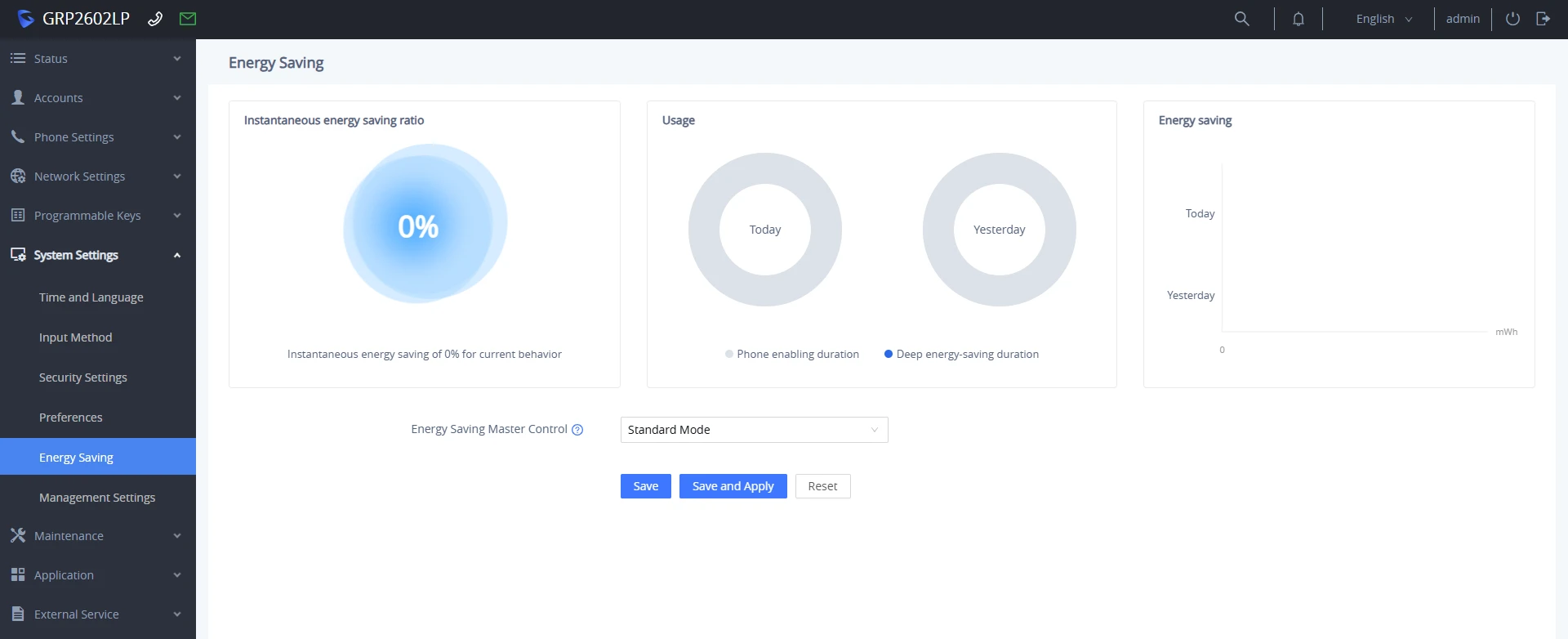
System Settings → Energy Saving | |
Instantaneous energy saving ratio | Shows a live energy-saving ratio preview based on the energy-saving mode selected. |
Usage | Displays the Deep energy saving duration relative to the phone’s enabling duration |
Energy saving | Displays a diagram of energy spent in MWh throughout the phone’s activity period. By default, it shows a comparison between the energy spent in the current day and the day before. |
Energy Saving Master Control |
Note: in the Customized Energy Saving mode, if the configured idle LCD brightness is greater than active LCD brightness , an error message will be displayed. By default set to “Standard Mode”. |
Backlight Brightness: Active | Configures the LCD brightness when the phone is active. Valid range is 0 to 8 where 0 is off and 8 is the brightest. |
Backlight Brightness: Idle | Configures the LCD brightness when the phone is idle. Valid range is 0 to 8 where 0 is off and 8 is the brightest,and its value cannot exceed the active value. |
Active Backlight Timeout | Configures the timeout interval of the LCD backlight. The valid range is 0 to 90. |
Enable Missed Call Backlight | If set to “Yes”, the LCD backlight will be turned on when there is a missed call on the phone. It cannot be set to “Yes” in full energy-saving mode. |
Management Settings
System Settings → Management Settings | |
Management Interface | |
Enable Secondary Network Interface | Enables or disables a virtual network interface layered on top of the phone’s physical Ethernet port. This isolates device management traffic onto a separate network segment from primary VoIP call traffic. This setting is disabled by default. |
WEB/SSH via | Configures which network interface accepts Web GUI (HTTP/HTTPS) and SSH remote management connections. The options are:
|
SNMP via | Configures which network interface is used for Simple Network Management Protocol (SNMP) and trap notifications. The default setting is “Primary Network Interface”. |
TR-069 via | Configures which network interface is used for TR-069 management sessions. The default setting is “Primary Network Interface”. |
Syslog via | Configures which network interface is used to send outbound Syslog monitoring messages to the remote Syslog server. The default setting is “Primary Network Interface”. |
Secondary Network Interface IPv4 Address | |
802.1Q/VLAN Tag | Assigns the IEEE 802.1Q VLAN ID tag to encapsulate Layer 2 management traffic on the secondary network interface. The default setting is 0 (VLAN tagging disabled). The vaid range is 0-4094. |
802.1p Priority Value | Assigns the IEEE 802.1p Class of Service (CoS) Layer 2 QoS priority bits to management traffic on the secondary interface. The default setting is 0. The vaid range is 0-7. |
IPv4 Address Type | Configures how the phone obtains its IPv4 network settings for the secondary management interface. The options are:
|
IPv4 Address | Configures the static IPv4 address assigned to the secondary management interface. Applicable only when IPv4 Address Type is set to Static. |
Subnet Mask | Configures the subnet mask corresponding to the secondary management interface’s static IPv4 network segment. Applicable only when IPv4 Address Type is set to Static. |
Gateway | Configures the default gateway IP address used to route traffic outside the local management subnet. Applicable only when IPv4 Address Type is set to Static. |
TR-069 | |
Enable TR-069 | Enables or disables the TR-069 protocol interface for automated device provisioning, monitoring, and remote management. |
ACS URL | Configures the full HTTP/HTTPS URL path of the TR-069 Auto Configuration Server (ACS). Default setting is: https://euacs.gdms.cloud |
TR-069 Username | Configures the authentication username required by the ACS to authenticate the phone during TR-069 session establishment. |
TR-069 Password | Configures the authentication password associated with the TR-069 Username required by the ACS to authenticate the device. |
Periodic Inform Enable | Enables or disables automated periodic INFORM messages sent from the phone to the ACS to maintain status updates and session connectivity. The default setting is “No”. |
Periodic Inform Interval | Configures the interval frequency (in seconds) at which the phone sends periodic INFORM packets to the ACS. Default is 86400. |
Connection Request Username | Configures the HTTP/HTTPS authentication username used by the ACS when initiating inbound connection requests to the phone. |
Connection Request Password | Configures the HTTP/HTTPS authentication password used by the ACS when initiating inbound connection requests to the phone. |
Connection Request Port | Configures the local listening port on the phone reserved for inbound connection requests from the ACS. |
CPE SSL Certificate | Uploads or specifies the Customer Premises Equipment (CPE) client certificate file used to establish secure mutual TLS connections with the ACS. |
CPE SSL Private Key | Uploads or specifies the private key file corresponding to the CPE SSL Certificate for secure ACS authentication. |
Start TR-069 at Random Time | When enabled, TR-069 will send out first INFORM message to server on randomized timing between 1 to 3600 seconds after phone boots up. |
SNMP Settings | |
Enable SNMP | Enables or disables the Simple Network Management Protocol (SNMP) service on the phone for network monitoring. Default settings is “No”. |
Version | Configures the SNMP protocol version supported by the device. The supported options are
Default is “Version 3”. |
Port | Configures the listening port reserved for incoming SNMP queries and requests. The valid range is 161, 1025-65535. The default value is “161”. |
Community | Configures the shared community string (password) required to authenticate queries when using legacy SNMP Version 1 or Version 2. |
Security Level | Configures the cryptographic security profile for SNMPv3 sessions:
The default setting is “noAuthUser”. |
SNMP Username | Configures the user identity name used for SNMPv3 authentication and access authorization. |
Authentication Protocol | Configures the hashing algorithm used to verify user identity credentials for SNMPv3 authentication.
The default setting is “None”. |
Privacy Protocol | Configures the encryption algorithm used to encrypt payload data for SNMPv3 sessions. The options are:
The default setting is “None”. |
Authentication Key | Configures the secret authentication password/key used by the MD5 or SHA hashing protocol for SNMPv3 user identity verification. |
Privacy Key | Configures the secret encryption passphrase/key used by the DES or AES algorithm to encrypt SNMPv3 payload data. |
SNMP Trap Version | Configures the SNMP trap protocol version used when sending unsolicited event notifications to the SNMP monitoring server. The options are:
The default is “Trap Version 2”. |
SNMP Trap IP | Configures the target IPv4 address or hostname of the remote SNMP trap receiver server. |
SNMP Trap port | Configures the destination port on the trap receiver server to which notification messages are sent. The valid range is 162, 1025-65535. The default value is “162”. |
SNMP Trap Interval | Configures the time interval (in minutes) between consecutive trap notification transmissions sent to the trap receiver. The valid range is 1-1440. The default value is “5” |
SNMP Trap Community | Configures the community string attached to outbound trap notification packets for authentication by the SNMP trap receiver. |
SNMP Trap Username | Configures the username required for SNMPv3 Trap authentication and access authorization. |
Trap Security Level | Configures the cryptographic security profile for SNMPv3 Trap transmissions:
The default setting is “noAuthUser”. |
Trap Authentication Protocol | Selects the authentication hashing protocol used for SNMPv3 Trap user verification.
The default setting is “None”. |
Trap Privacy Protocol | Selects the encryption algorithm used to secure SNMPv3 Trap payload data when Security Level is set to privUser (authPriv). The options are:
The default setting is “None”. |
Trap Authentication Key | Configures the secret authentication key/passphrase used by the MD5 or SHA hashing protocol for SNMPv3 Trap identity verification. |
Trap Privacy Key | Configures the secret encryption key/passphrase used by the AES or DES algorithm to encrypt SNMPv3 Trap payload data. |
Maintenance Page Definitions
Upgrade and Provisioning
Maintenance → Upgrade and Provisioning | |
Firmware | |
Upgrade via Manually Upload | |
Upload Firmware File to Update | Allows local uploading of a binary (.bin) firmware image file directly from the computer to trigger an immediate firmware update and reboot. |
Upgrade via Network | |
Firmware Upgrade via | Configures the network transfer protocol used for the remote firmware server. The options are:
The default setting is “HTTP”. |
Firmware Server Path | Configures the IP address, or domain of the remote server hosting the firmware files. |
Firmware Server Username | Configures the authentication username required to access protected firmware server directories. |
Firmware Server Password | Configures the authentication password associated with the Firmware Server Username. |
Firmware File Prefix | If configured, the device will only download and use firmware images that match this exact starting prefix string. |
Firmware file Postfix | If configured, the device will only download and use firmware images that match this exact ending postfix string. |
Upgrade Detection | |
Upgrade | Triggers an immediate request to the configured firmware server path to check for newer firmware versions and initiate an automatic upgrade process. |
Config File | |
Configure Manually | |
Download Device Configuration | Exports the phone’s full active configuration settings as a plain text (.txt) configuration file. Note: The exported file excludes sensitive authentication passwords, CA certificates, and user-uploaded custom security certificates. |
Download Device Configuration (XML) | Exports the phone’s full active configuration settings as an XML-formatted (.xml) file. Note: The exported file excludes sensitive authentication passwords, CA certificates, and user-uploaded custom security certificates. An “XML Help document” link is available alongside this setting to download a reference XML formatting template. |
Download User configuration | Exports a targeted user configuration file containing only customized local changes made via the Web GUI or manually uploaded files. Note: The exported sensitive identity credentials (usernames/passwords) and removes settings provisioned remotely from automated servers via TFTP/FTP/FTPS/HTTP/HTTPS. |
Upload Device Configuration | Allows manual uploading of a local configuration file (.txt or .xml) to apply settings directly to the phone. |
Upload Third-party Vendor Configuration | Uploads and converts configuration files from supported non-native IP phone vendors to automatically apply matching parameters on the phone. Supported Vendors: Yealink and Fanvil configuration files. |
Export backup Package | Generates and exports a complete, compressed system backup archive containing both global phone configuration parameters and local user data. |
Restore from Backup package | Restores full system configuration settings and personal data by uploading a previously exported backup archive package. |
Configure via Network | |
Config Upgrade Via | Configures the network protocol used to communicate with the provisioning server and download configuration files. The options are:
The default setting is “HTTPS”. |
Config Server Path | Defines the IP address or domain name of the provisioning server. Note: If a protocol prefix (e.g., https://) is explicitly included in this string, it overrides the protocol selected in the Config Upgrade Via parameter. |
Config Server Username | Configures the authentication username used to access protected provisioning directories on the config server. |
Config Server Password | Configures the authentication password associated with the Config Server Username. |
Always Authenticate Before Challenge | When enabled, the phone proactively sends authentication headers with its initial request rather than waiting for an unauthorized challenge from the server. |
Config File Prefix | If specified, the phone will strictly download and process configuration files matching this exact prefix string. |
Config File Postfix | If specified, the phone will strictly download and process configuration files matching this exact postfix string. |
Authenticate Conf File | Enables cryptographic signature verification for downloaded configuration files to ensure authenticity and integrity before applying settings to the device. |
XML Config File Password | Configures the decryption key required to decrypt OpenSSL AES-encrypted XML configuration files (cfg<MAC>.xml) retrieved from the provisioning server. |
Provision | |
Auto Upgrade | |
Automatic Upgrade | Enables automated checking for updated firmware files and configuration provisioning files on remote servers. The options are:
The default setting is “No”. |
Automatic Upgrade Check Interval (m) | Configures the check interval frequency in minutes. The valid Range is 60 to 5256000 minutes. The default setting is “10080” minutes (7 days). |
Hour of the Day (0-23) | Defines the specific hour of the day (in 24-hour format) to contact the server and execute the upgrade check. The default setting is “1” minutes (1:00 AM). |
Day of the Week (0-6) | Defines the exact day of the week to contact the server for firmware and configuration file updates. The default setting is 1 (Monday). |
Start Upgrade at Random Time | Configures whether the phone will upgrade automatically at a random time within the configured time interval. The default setting is “No” |
Firmware Upgrade and Provisioning | Controls how the phone processes firmware updates relative to configuration provisioning checks:
|
Firmware Upgrade Confirmation | Configures whether interactive user confirmation on the phone’s LCD display is required before downloading and applying new firmware updates: The default setting is “Yes”. |
DHCP Option | |
Allow DHCP Option 43 and Option 66 Override Server | Configures whether the phone accepts provisioning server paths received dynamically via DHCP Option 66 (TFTP/HTTP server name/URL) or DHCP Option 43 (vendor-specific info) to override static server settings. The options are:
The default setting is “Yes”. |
Allow DHCP Option 120 to override SIP Server | Enables or disables processing of DHCP Option 120 (SIP Outbound Proxy/Server addresses) received from the local DHCP server to automatically override configured SIP server addresses on the device. The default setting is “No”. |
Additional Override DHCP Option | Allows selection of custom DHCP options to provide alternative provisioning/firmware server URLs dynamically from the network. This option is effective only when Allow DHCP Option 43 and Option 66 to Override Server is enabled. The default setting is “Option 150”. |
Config Provision | |
Download and Process ALL Available Config Files | Controls how the phone searches for, downloads, and processes configuration files from the provisioning server. The options are:
The default setting is “No”. |
User Protection | Protects locally customized user settings from being overridden during remote auto-provisioning updates. When enabled, any configuration P-values modified manually by the user are protected and will not be overwritten by server provision files. The default setting is “No”. |
Auto Provision | When enabled, the phone sends out multicast SUBSCRIBE messages across the local network to automatically discover and auto-configure with compatible IP-PBX platforms (such as 3CX or Grandstream UCM series). The default setting is “Yes”. |
Advanced Settings | |
Validate Hostname in Certificate | Configures whether the phone verifies that the server domain name or IP address matches the server’s SSL certificate during HTTPS, TLS, or FTPS connections. The default setting is “No”. |
Enable SIP Notify Authentication | Controls whether the phone requires Digest Authentication for incoming SIP NOTIFY messages (e.g., remote resync or check-sync requests from the server). The options are:
The default setting is “Yes”. |
Factory reset | Triggers a full system restore to factory default settings. |
Recovery Mode | Initiates Recovery Mode host functionality to recover other phones on the local network that have corrupted flash memory. The recovery procedure is:
|
System Diagnostics
Maintenance → System Diagnosis | |
Syslog | |
Syslog Protocol | Configures the network transport layer protocol used to transmit log messages to the remote Syslog server. The options are:
Default setting is “UDP”. Note: The CA certificate is required to connect with the TLS server. |
Syslog Server | Configures the IPv4 address, IPv6 address, or FQDN of the destination Syslog server receiving system logs. Note: By adding port number to the Syslog server field (i.e., 172.18.1.1:1000), the phone will send syslog to the corresponding port of that IP. |
Syslog Level | Defines the minimum log severity threshold to send to the server. Syslog messages are sent based on the following events:
The default setting is “NONE”. |
Syslog Header Format | Configures the preferred header format for Syslog. The options are:
The RFC3164 compliant header begins with “PRI” which represent both the Facility (0 – 23) and severity level (0 – 7) of the event. The message includes the timestamp, hostname, process id and the log message. For more information regarding the representation of the numerical values for the facility and severity, please refer to RFC3164. |
Syslog Keyword Filter | Syslog will be filtered based on keywords provided. If you enter multiple keywords, they should be separated by ‘,’. Please note that no spaces are allowed. |
Send SIP Log | Configures whether the SIP log will be included in the syslog messages. The default setting is “No”. Note: By setting Send SIP Log to Yes, the phone will still send SIP log from syslog even when Syslog Level set to NONE. |
Maintain System Log Information after Factory Reset | If Enabled, syslog settings and internal logs will be saved across a factory reset. Disabled by default. |
Packet Capture | |
With RTP Packets | Defines whether the packet capture file contains RTP or not. The default setting is “No”. Note: This option is enabled by default. |
Generate WLAN Session Keys File | After this configuration is enabled, the packet capture will carry the WLAN session key file, named 80211_keys, which records the WLAN session keys that the device has gone through from the start to the end of the capture process. Note: This option is disabled by default. |
With Secret Key Information | Configures whether the packet capture file contains secret key information or not. This option is enabled by default |
Packet Capture Data Coverage | Controls packet capture behavior when the trace data file reaches its maximum storage limit of 2.5 MB. The options are:
Note: This option is disabled by default. |
Ping | |
Ping | Enter Ping target’s IP address or URL and click on start. |
Traceroute | |
Traceroute | Input target’s IP address or URL and click on start |
Remote Diagnostics | |
Remote Diagnostics | When enabled, this device will allow remote access and remote collection of logs. It will automatically end when it expires. |
Start | To begin the remote diagnostics, click the “start” button |
Access Address | Displays the IP Address and port number of the access address |
Expiration Time | Displays the Expiration time of the Remote Diagnostics , The Expiration time is set to 48 hours since the start of the Remote Diagnostics |
Outbound Notification
Maintenance → Outbound Notification | |
Action URL | |
Phone Status | |
Setup Completed | Configures the Action URL to send when phone finishes setup process. |
Registered | Configures the Action URL to send when phone successfully registers a SIP account. |
Unregistered | Configures the Action URL to send when phone unregisters a SIP account. |
Register failed | Configures the Action URL to send when phone fails to register a SIP account. |
Idle to Busy | Configures the Action URL to send when phone’s state changes from idle to busy. |
Busy to Idle | Configures the Action URL to send when phone’s state changes from busy to idle. |
Auto Provision Completed | Configures the Action URL to send when phone’s auto provisioning process is completed. |
IP Change | Configures the Action URL to send when the IP address changes. |
Call Operation | |
Off-hook | Configures the Action URL to send when phone is in off-hook state. |
On-hook | Configures the Action URL to send when phone is in on-hook state. |
Incoming Call | Configures the Action URL to send when phone receives an incoming call. |
Outgoing Call | Configures the Action URL to send when phone places a call. |
Missed Call | Configures the Action URL to send when phone has a missed call. |
Established Call | Configures the Action URL to send when phone establishes a call. |
Forwarded Call | Configures the Action URL to send when phone forwards an incoming call. |
Terminated Call | Configures the Action URL to send when phone terminates a call. |
Answered Call | Configures the Action URL to send when phone answers an incoming call. |
Rejected Call | Configures the Action URL to send when phone rejects an incoming call. |
Blind Transfer | Configures the Action URL to send when phone performs blind transfer. |
Attended Transfer | Configures the Action URL to send when phone performs attended transfer. |
Transfer Completed | Configures the Action URL to send when phone successfully transfers a call. |
Transfer Failed | Configures the Action URL to send when phone fails to transfer a call. |
Hold Call | Configures the Action URL to send when phone places a call on hold. |
Unhold Call | Configures the Action URL to send when phone resumes the call on hold. |
Mute Call | Configures the Action URL to send when phone mutes a call. |
Unmute Call | Configures the Action URL to send when phone unmutes a call. |
Call Settings | |
Enable DND | Configures the Action URL to send when phone enables DND. |
Disable DND | Configures the Action URL to send when phone disables DND. |
Enable Call Forward | Configures the Action URL to send when phone enables Call Forward. |
Disable Call Forward | Configures the Action URL to send when phone disables call forward. |
Open Forward Always | Configures the Action URL to send when phone enables call forward always function. |
Close Forward Always | Configures the Action URL to send when phone disables call forward always function. |
Open Call Forward Busy | Configures the Action URL to send when phone disables call forward always function. |
Close Call Forward Busy | Configures the Action URL to send when phone disables call forward busy function |
Open Call Forward No Answer | Configures the Action URL to send when phone enables call forward no answer function. |
Close Call Forward No Answer | Configures the Action URL to send when phone disables call forward no answer function. |
Destination | |
Destination Name | Identify the destination name. It must be unique. |
Protocol | Configure the protocol associated with the destination server. Currently XMPP and SMTP are supported. |
Enable SSL | Configure whether to use SSL to encrypt for SMTP protocol. This option is not editable for XMPP. |
Destination Address | Configure destination server address, e.g., talk.google.com. |
Port | Configure destination server port, e.g., 5222. |
Domain | Configure the destination server domain for XMPP protocol. This option is not editable for SMTP. |
Username | Configure the authorization username of the destination server. |
Password | Configure the authorization user password for the destination server. |
From | Configure the sender name for SMTP protocol. This option is not editable for XMPP. |
To | Configure the receiver’s address. |
Extra Attribute Name | Configure extra attribute’s name reserved for protocol specific attributes such as “jid” for XMPP protocol. If “jid” is specified, username and domain will be overridden. |
Extra Attribute Value | Configure extra attribute’s value reserved for protocol specific attributes such as “abc@gmail.com” for “jid” of XMPP protocol. If it is specified, username and domain will be overridden. |
Notification | |
Event | Configures the event, which will trigger an outbound notification. |
Destination | Configures the name of the destination where the outbound notification will be sent. |
Subject | Configures the subject of the email notification. This option is only applicable to the SMTP protocol, and it is not editable for other protocols. |
Message | Configures the message body or the outbound notification. |
Extra Attribute Name | Configure extra attribute’s name reserved for specific attributes for a given notification in the future. |
Extra Attribute Value | Configures extra attribute’s value reserved for specific attributes for a given notification in the future. |
Voice Monitoring
Maintenance → Voice Monitoring | |
Session Report | |
VQ RTCP-XR Session Report | Enables or disables generating a Voice Quality (VQ) summary report at the end of each SIP call session via RTCP-XR, which sends metrics such as jitter, packet loss, and MOS scores to the collector server upon call termination. This option is disabled by default. Note: the GRP260x Lite uses the same server/port that is used for SIP registration to process XR session reports |
Interval Report | |
VQ RTCP-XR Interval Report | Enables or disables sending periodic Voice Quality RTCP-XR reports to the collector server while a call is active. The default setting is No. |
VQ RTCP-XR Interval Report Period | Sets the time interval (in seconds) between periodic RTCP-XR voice quality reports sent during an active call. The default value is 20 seconds. |
Alert Report | |
Warning Threshold for Moslq | Configure the threshold value of listening MOS score (MOS-LQ) multiplied by 10. The threshold value of MOS-LQ causes the phone to send a warning alert quality report to the central report collector. |
Critical Threshold for Moslq | Configure the threshold value of listening MOS score (MOS-LQ) multiplied by 10. The threshold value of MOS-LQ causes the phone to send a critical alert quality report to the central report collector. |
Warning Threshold for Delay | Configure the threshold value of one way delay (in milliseconds) that causes the phone to send a warning alert quality report to the central report collector. |
Critical Threshold for Delay | Configure the threshold value of one way delay (in milliseconds) that causes the phone to send a critical alert quality report to the central report collector. |
Display Report | |
Display Report on Web UI | Controls whether call quality diagnostics and summary reports are displayed within the phone’s Web GUI call status pages. This option is enabled by default. |
Display Report on LCD | Controls whether voice quality summary statistics are displayed on the LCD phone screen during or immediately following a call. This option is disabled by default. |
Custom Display Layout on LCD | Configures the specific voice quality metrics displayed on the phone LCD screen. The options are:
|
Scheduled Tasks
Maintenance → Scheduled Tasks | |
Working Time | Configures office hours for the effective time configuration of scheduled tasks. For example: set the phone to lock during non-working hours, set it forward during working hours. |
Scheduled Tasks | |
Add | Configures a new shceduled task based on :
|
Delete | Deletes the Scheduled Tasks |
Application Page Definitions
Web Service
Application → Web Service | |
Use Auto Location Service | Configures whether the phone automatically queries Grandstream cloud servers via DNS upon boot to determine its local geographical location. Note: A device reboot is required for changes to take effect. |
XML Application
Application → XML Application | |
Idle Screen | |
Idle Screen XML Download | Configures whether to enable XML idle screen downloading and selects the network transfer protocol used to fetch the custom screen XML file. The options are:
|
Download Screen XML at Boot-up | Configures whether the phone automatically downloads the custom idle screen XML file from the server during device bootup. The default setting is No. |
Use Custom Filename | Controls how the custom idle screen XML file is named on the server. If set to “Yes” custom filenames are allowed. The full file name must be specified in the Idle Screen XML Server Path field. The default setting is “No”. |
Idle Screen XML Server Path | Defines the server address and path for the custom XML idle screen file. Format: IP_address/path or URL/path (e.g., 192.168.1.50/xml/idle.xml). |
XML File Example | Click to download a sample reference XML template file. Note: To customize softkeys locally on the phone while ignoring softkey layout definitions inside the downloaded XML file, add the attribute <SoftKeys ignore=”true”> into the XML syntax. |
Top Screen | |
Softkey Label | Configures the display name/text label shown on the phone’s softkey button used to access the custom XML application from the idle screen. |
Server Path | Configures the remote server URL or IP address path from which to fetch the XML application content. This field can be an IP address or URL, with up to 256 characters. |
Contacts
Application → Contacts | |
Contacts | |
Add Contact | Press Add to create a new contact.
|
Edit | Edits the contact parameters. |
Delete | Deletes a specific contact entry. |
Delete All Contacts | Press to delete all contacts. |
Group Management | |
Add Group | Specifies Group’s name to add new group. More than 30 Groups are supported. |
Edit Group | Edits selected group. |
Delete Group | Delete Selected group. |
Phonebook Management | |
Enable Phonebook XML Download | Configures whether to enable automatic XML phonebook file downloading and selects the protocol used to download the file from the remote server. The options are:
The default setting is “Disabled”. |
HTTP/HTTPS Username | Defines the authentication username required to access protected directories on the HTTP/HTTPS server when fetching the XML phonebook file. |
HTTP/HTTPS Password | Defines the authentication password associated with the HTTP/HTTPS Username. |
Phonebook XML Server Path | Specifies the IP address or full URL path of the remote server hosting the phonebook XML file. This field supports up to 256 characters. |
Phonebook Download Interval | Configures the phonebook download interval (in minutes). If set to 0, automatic download will be disabled. The default value is 0. The valid range is 5 to 720 minutes. |
Remove Manually-edited Entries on Download | If set to “Yes”, when the XML phonebook is downloaded, the entries added manually will be automatically removed. The default setting is “Yes”. |
Import Group Method | Determines how newly imported phonebook contact groups interact with existing local contact groups:
The default setting is “Replace”. |
Sort Phonebook by | Controls how entries in the phone directory are sorted and displayed:
The Default setting is “Auto”. |
Download XML Phonebook | Exports the phone’s current active XML phonebook database to the local computer. |
Upload XML Phonebook | Manually uploads a pre-configured XML phonebook file directly from the local computer onto the device. |
Default Search Mode | Sets the default search matching behavior used when searching through phonebook contacts:
The default setting is “Full Fuzzy Match”. |
LDAP
Application → LDAP | |
Obtain from UCM Server | |
Obtain LDAP configuration file | Sets the option to obtain the LDAP configuration file from the UCM the phone is registered to. Note: Enabling this setting overwrites any existing local LDAP configuration file stored on the device. |
Enable UCM LDAP Auto-config Feature on LCD | Controls whether the UCM LDAP auto-configuration setup option appears as a softkey on the phone’s LCD. This option is enabled by Default. |
Manual Import | |
Import LDAP configuration file | Uploads an XML-formatted LDAP configuration file directly to the phone. Users can also click to download an example XML file link to obtain a reference template. Note: Uploading a new file overwrites the original LDAP configuration settings on the device. |
Local Configuration | |
LDAP Protocol | Configures the network protocol used to communicate with the LDAP directory server:
The default setting is “LDAP”. |
LDAP Version | Specifies the LDAP protocol version used by the target directory server. The options are:
The default setting is “Version 3”. |
Server Address | Configures the IP address, or FQDN of the LDAP directory server. |
Port | Sets the port used to connect to the LDAP server. The default port number is “389”. Note: Standard LDAPS connections typically use port 636. |
Base DN | Specifies the Base Distinguished Name (DN) defining the starting top-level node in the LDAP directory hierarchy for search queries. Example: ou=users,dc=grandstream,dc=com |
Username | Configures the username used to authenticate against the LDAP server if anonymous binding is disabled. |
Password | Configures the authentication password associated with the bind Username. |
LDAP Number Filter | Defines the filter search string used to perform caller ID matching or directory queries against telephone number attributes when receiving or placing calls. Examples:
|
LDAP Name Filter | Defines the filter search string used when searching contacts by name from the phone. Examples:
|
LDAP Mail Filter | Defines the search filter criteria used to query email address entries in the LDAP directory. Examples:
|
LDAP Position Filter | Defines the filter search string used to match job titles or professional positions within the LDAP directory. |
LDAP Department Filter | Defines the filter search string used to query or group contacts by organizational department within the LDAP database. |
LDAP Number Attributes | Specifies the attribute names in the LDAP database containing phone numbers for entries, delimited by spaces. Example:
|
LDAP Name Attributes | Specifies the attribute names in the LDAP database containing contact names, separated by spaces. Example:
|
LDAP Mail Attributes | Specifies the attribute names in the LDAP database containing email addresses, separated by spaces. Example: mail |
LDAP Position Attributes | Specifies the attribute names in the LDAP database containing email addresses, separated by spaces. Example:
|
LDAP Department Attributes | Specifies the attribute names in the LDAP database containing organizational department designations. Example: department |
LDAP Display Name | Configures the entry attribute format displayed on the phone screen for LDAP search results. Up to 3 fields can be displayed. Example: %cn %sn %telephoneNumber |
Max. Hits | Specifies the maximum number of results to be returned by the LDAP server. If set to 0, server will return all search results. The valid range is 0-3000 and the default setting is 50. |
Search Timeout | Specifies the interval (in seconds) for the server to process the request and client waits for server to return. The valid range is 0-180 and the default setting is 30 seconds. |
Sort Results | Specifies whether the searching result is sorted or not. The default setting is “No”. |
Exact Match Search | Forces LDAP queries to return only entries that exactly match the typed input string. The default setting is “No”. |
LDAP Dialing Default Account | Specifies the default SIP account used to place outgoing calls when dialing directly from an LDAP contact lookup. |
LDAP Lookup | Enables dynamic background LDAP caller ID lookups:
Both options are unchecked by default. |
Lookup Display Name | Specifies the format string used to render the contact’s name on screen during active incoming or outgoing LDAP lookup events. Example:
|
Remote Phonebook
Application → Remote Phonebook | |
*Up to 5 XML Remote Phonebooks. | |
Display Name | Configures the custom label displayed on the phone’s LCD screen and Web UI to identify the specific remote phonebook. |
URL | Specifies the IP address or full URL path hosting the XML phonebook file. |
Username | Configures the authentication username required to access the server hosting the XML phonebook file, if HTTP/HTTPS authentication is enabled. |
Password | Configures the authentication password associated with the Username. |
Remote Phonebook Update Interval | Configures the automatic background synchronization interval (in minutes) for downloading fresh XML phonebook files. If set to 0, automatic download will be disabled. Valid range is 5 to 720. |
Call History
The call history page allows administrators and users to view, filter, and manage stored call records, including answered, dialed, missed, and blocked calls.
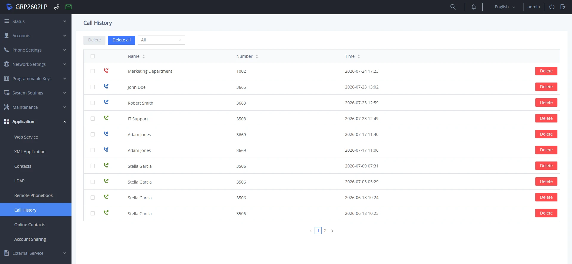
Application → Call History | |
Delete | Removes selected individual call log records from the call history list. Alternatively, click the red Delete button next to a specific record row. |
Delete All | Clears and deletes all stored call history logs across all categories from the phone. |
Call History Type Filter | Filters the displayed call records by category:
|
Online Contacts
Online Contacts configures real-time external contact searching via HTTP/HTTPS GET or POST requests, enabling integration with enterprise CRMs or web services using dynamic query variables and custom JSON/XML response syntax.
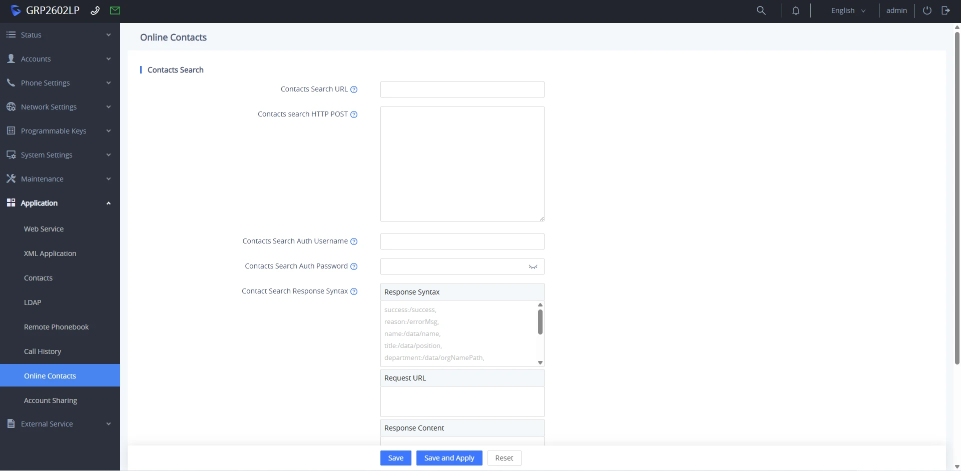
Application → Online Contacts | |
Contacts Search URL | Configures the target server URL used to search contacts (Up to 256 characters). This field can include the protocol, server address, path, or query parameters. If Contacts search HTTP POST is left empty, the phone automatically issues an HTTP GET request to this URL. Path and query parameters support built-in dynamic variables using the {var} format:
Example: URL: http://ip:port/getUserInfoByNumber/{remoteNumber} |
Contacts search HTTP POST | Configures the HTTP POST payload body used to query contacts. This field can include protocol, server address, path, or query parameters, with up to 1024 characters and both XML and JSON data format support. When this field contains data, the phone automatically sends an HTTP POST request instead of GET. This field also supports all standard {var} built-in dynamic variables listed above. |
Contacts Search Auth Username | Sets the authentication username for accessing the HTTP/HTTPS search server. |
Contacts Search Auth Password | Sets the authentication password for accessing the HTTP/HTTPS search server. |
Contact Search Response Syntax | Configures mandatory response parsing rules and provides interactive testing tools: Response Syntax: Defines key-path mapping formatted as key:val[,key:val], where commas , act as newline delimiters. Supported Keys: ● success ● reason ● counts ● total ● name ● company ● department ● title ● firstName ● lastName ● extensionCompany ● extensionHome ● extensionMobile Example: ● success:/success, ● reason:/errorMsg, ● name:/data/name, ● title:/data/position, ● department:/data/orgNamePath Request URL & Response Content: Testing tools used to execute test queries and display raw server response payloads for syntax verification. |
Account Sharing
Account Sharing allows guest phones to place and receive external calls via a host phone’s registered SIP account without needing individual IP-PBX account registrations.
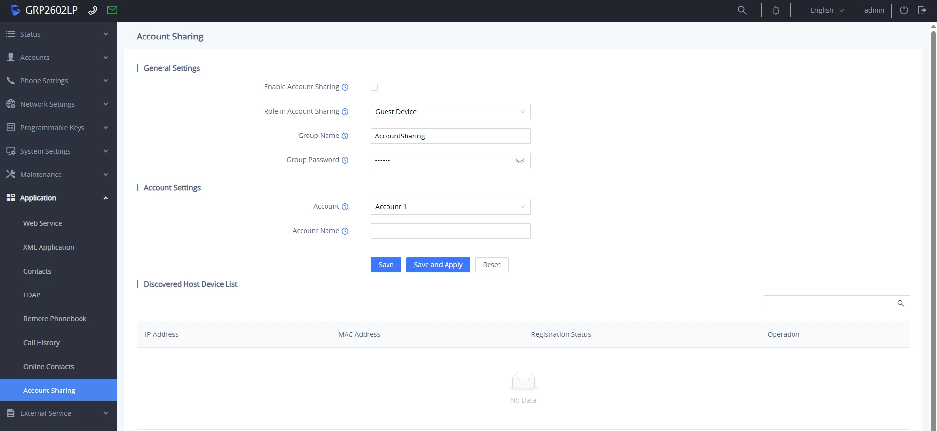
Application → Account Sharing | |
General Settings | |
Enable Account Sharing | Controls whether the Account Sharing feature is enabled on the device. This is disabled by default. |
Role in Account Sharing | Defines the operational role of the device on the local network. The options are:
The default role is “Guest Device”. |
Group Name | Sets the shared group identifier used for mutual device discovery across the local network. Devices must share the exact same Group Name to discover each other. |
Group Password | Sets the authentication password for the sharing group. Guest devices must match the Host Device’s Group Password to successfully authenticate and register to the host. |
SIP Server Port | Sets the local SIP service port used for device Account Sharing communication, where 0 indicates using a random port, ranging from 0 to 65535. The default port number is “15060”. |
Account Settings | |
Account | Configures account assignment based on device role:
|
Account Name | Specifies the label or account name corresponding to the shared account used by the guest device. |
Ringing Tone Settings | |
Sync Ringing In Group | Synchronizes ringtone across all registered guest devices within the Account Sharing group so they ring simultaneously in phase when an incoming call arrives. This is disabled by default. |
Ringtone | Selects the ringtone file played on the devices when an incoming call arrives via the shared account. Only applicable when “Sync Ringing In Group” is enabled. |
Discovered Host Device List (Guest Mode) | |
IP Address | Shows the local network IP address of the discovered Host Device broadcasting within the same sharing group. |
MAC Address | Shows the unique hardware MAC address of the discovered Host Device. |
Registration Status | Indicates the connection/registration state between this guest phone and the target Host Device. |
Operation | Displays the available operation controls for monitoring and managing the host-discovered device on the local network. |
Discovered Guest Device List (Host Mode) | |
IP Address | Shows the local network IP address of the Guest Device registered or attempting to register to this host. |
MAC Address | Shows the unique hardware MAC address of the discovered Guest Device. |
Account Name | Displays the SIP extension or account name assigned to the Guest Device for shared calling. |
Registration Status | Indicates the active registration status of the Guest Device on this host. |
Operation | Displays the available operation controls for monitoring and managing the discovered guest device on the local network. |
External Service Page Definitions
GDS
External Service → GDS | |
Order | Indicates the entry index number for configuring up to 10 external door system rules. |
Service Type | Selects the integration type for the door entry system. The options are:
|
Account | Specifies which registered SIP line account on the phone is used to communicate with the corresponding door device and trigger door unlock commands. |
Access Number | Sets the destination address used to contact the door station. Users can enter the assigned SIP extension or IP address of the door device, depending on the deployed scenario. |
Ringtone | Selects the ringtone played on the phone when receiving an incoming call from the specified Access Number. |
Access Identification | Configures a custom descriptive label or name displayed on the phone’s LCD screen to identify the door station (e.g., “Front Gate” or “Main Entrance”). |
Access Password | Sets the DTMF password or PIN required to send a door unlock request to the door station. Note: For GDS37xx devices, this password must match the Remote PIN to Open the Door setting on the GDS unit. |
Call Center
This page configures Broadsoft call center feature controls on the phone, enabling agents to submit call outcome codes, set reason codes for taking breaks/going unavailable, and view automated wrap-up timers on the screen.
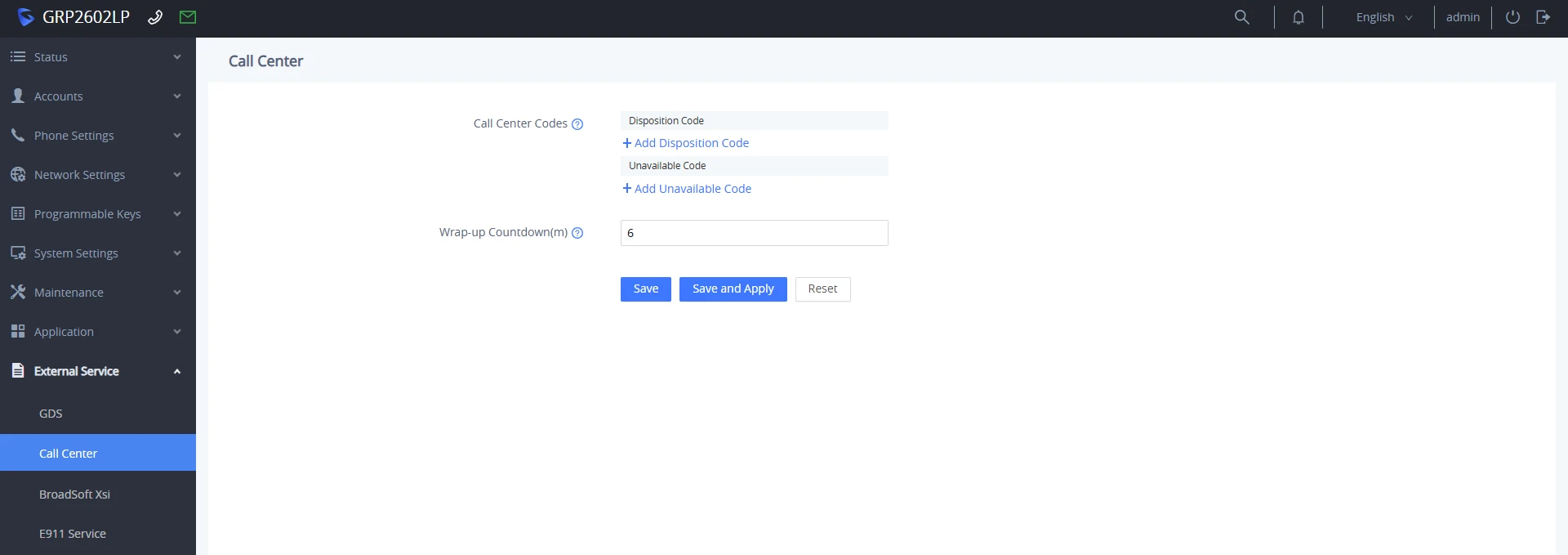
External Service → Call Center | |
Call Center Codes | Configures pre-defined DTMF or feature access codes that agents can quickly select on the phone’s softkeys/screen:
|
Wrap-up Countdown | Sets the post-call timer duration. When a call ends, the agent automatically enters Wrap-up state. Once the timer ends, the phone automatically transitions the agent back to Available state to receive the next queued call. If set to 0, the automatic wrap-up countdown is disabled. The valid range for the timer is 0 to 60 minutes, and the default setting is 6. |
BroadSoft Xsi
External Service → Broadsoft XSI | |
Authentication Login | |
Server | Configures the IP address or FQDN of the BroadSoft XSI server along with the transfer protocol. Example: [http://192.168.6.155] or [https://xsi.broadsoft.com] |
Port | Sets the HTTP or HTTPS port number used to connect to the BroadSoft XSI server. The default port is 3889. |
XSI Action Path | Specifies the application path on the BroadSoft server where XSI Action web services reside. If left blank, the phone automatically defaults to com.broadsoft.xsi-actions. |
XSI Authentication Type | Defines the authentication mechanism used for BroadSoft XSI server access:
The default setting is “Login Credentials”. |
BroadWorks User ID | Configures the BroadSoft user ID assigned for XSI server access. |
SIP Authentication ID | Displays or sets the SIP authentication ID used for BroadSoft XSI server authentication. This field is auto-filled when an Account (1-N) is selected in the account dropdown and editable when Customize is selected in the account dropdown. |
SIP Authentication Password | Displays or sets the SIP authentication password used for BroadSoft XSI server authentication. This field is auto-filled when an Account (1-N) is selected in the account dropdown, and editable when Customize is selected in the account dropdown. |
Login Password | Sets the password used to authenticate against the BroadSoft XSI server when using Login Credentials. |
Auto Login | When enabled, the phone automatically logs into the BroadSoft XSI server in the background upon booting up, allowing the device to continuously retrieve directories and update BroadSoft user services. |
Service Settings | |
Sort Phonebook by | Sort phonebook based on the selection of first name or last name. |
BroadSoft Directory Update Interval (m) | Configures the BroadSoft phonebook download interval (in minutes). If set to 0, automatic download will be disabled. Valid range is 5 to 4320. |
Broadsoft Contacts Download Limit | The maximum contacts that can be downloaded for each BroadSoft XSI server directory. The valid range is from 0 to 2000. If set to 0, the server’s default contact limit will be used. If the total contact records returned by the server is larger than this limit then it will not be downloaded, and the device will be limited to remote search. |
BroadSoft Contacts Search Limit | The maximum remote search records that can be downloaded for the BroadSoft XSI server directory. The valid range is from 0 to 2000. If set to 0, there is no limit. If the search result total records exceed this value, it will not be downloaded, and you will need to narrow the search scope. |
Network Directories | |
Type | Enable/Disable Broadsoft Network directories. The directory types are:
|
Name | Defines the directory name. |
E911 Service
External Service → E911 Service | |
Enable E911 | Enable Enhanced 911 call. Default is disabled |
HELD Protocol | Configure HELD transfer protocol. HTTP or HTTPS |
HELD Synchronization Interval. | The valid synchronization interval is between 30 to 1440 minutes. The synchronization is off when the interval is 0. |
Location Server | Configure the primary Location Information Server (LIS) address |
Location Server Username | Configure the user name of the primary Location Information Server (LIS) |
Location Server Password | Configure the password of the primary Location Information Server (LIS) |
Secondary Location Server | Configure the seconary Location Information Server (LIS) address. |
Secondary Location Server Username | Configure the user name of the secondary Location Information Server (LIS) |
Secondary Location Server Password | Configure the password of the secondary Location Information Server (LIS) |
HELD Location Types | Configure “locationType” element in the location request. “geodetic”, “civic” and “location URI” |
HELD Use LLDP Information | If “Yes”, the information from LLDP-suport switch is used to generate ChassisID and PortID; otherwise, the mac address of gateway and phone is used as default. |
HELD NAI | If “Yes”, Network Access Identifier (NAI) is included as a device identity in the location request sent to the Location Information Server (LIS) |
HELD Identity 1–10 | Defines the identity attribute name/type sent to the Location Information Server in the HELD request payload. Examples: ip, mac, uri, nai |
HELD Identity 1–10 Value | Defines the corresponding identity attribute value associated with the specified HELD Identity key. Examples: 192.168.1.50, 000B82XXXXXX, user@domain.com |
E911 Emergency Numbers | A user can configure multiple emergency numbers separated with the delimiter symbol “;”. |
Geolocation-Routing Header | If “Yes”, E.911 INVITE message includes the “Geolocation-Routing” header with the value “Yes” |
Geolocation Header Format | Choose the standard of the format of the Geolocation Header.
Note: By default this option is set to “Legacy”. |
Priority Header | If “Yes”, E.911 INVITE message includes the “Priority” header with the value “emergency” |
NAT SETTINGS
When devices are deployed within a private local network behind a NAT router or firewall, configuring NAT traversal settings ensures proper two-way SIP signaling and RTP media flow.
STUN Server
- Configuration Page: Phone Settings → General Settings.
- Description: Enter the IP address or Fully Qualified Domain Name (FQDN) of your target STUN server (e.g., stun.l.google.com:19302). The phone queries the STUN server to discover its public IP address and port mapping.
- Usage: If the device is assigned a public IP address directly, leave this field blank.
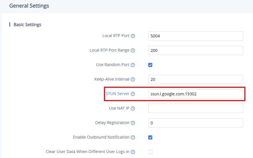
Use Random Ports
- Configuration Page: Phone Settings → General Settings.
- Description: Forces the device to randomly generate local SIP listening ports and RTP audio/video port ranges.
- Usage: This option is recommended when multiple IP phones reside behind the same NAT router/firewall to prevent port collision conflicts. If the phone uses a public IP address, you can disable this parameter.
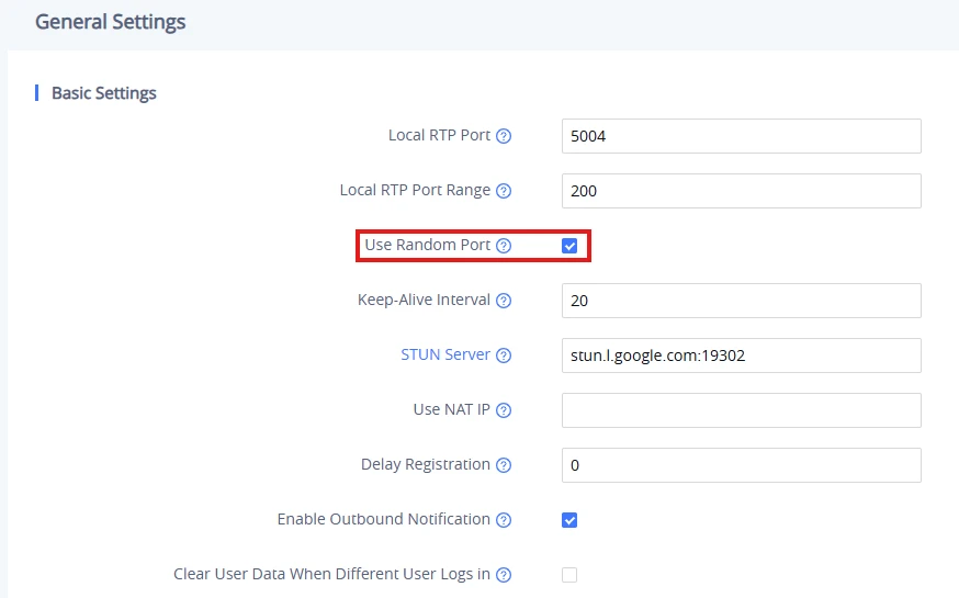
NAT Traversal
- Configuration Page: Accounts → Account X → Network Settings.
- Description: Defines how the specific SIP account handles NAT traversal when behind a firewall:
- No: Disables NAT traversal (used when device has a direct public IP or uses SBC/VPN).
- STUN: Uses the configured global STUN server to resolve external IP/port mappings.
- Keep-Alive: Sends periodic SIP keep-alive packets to keep NAT binding open on the router.
- Auto: The phone dynamically detects whether it is behind a NAT and applies appropriate traversal techniques.
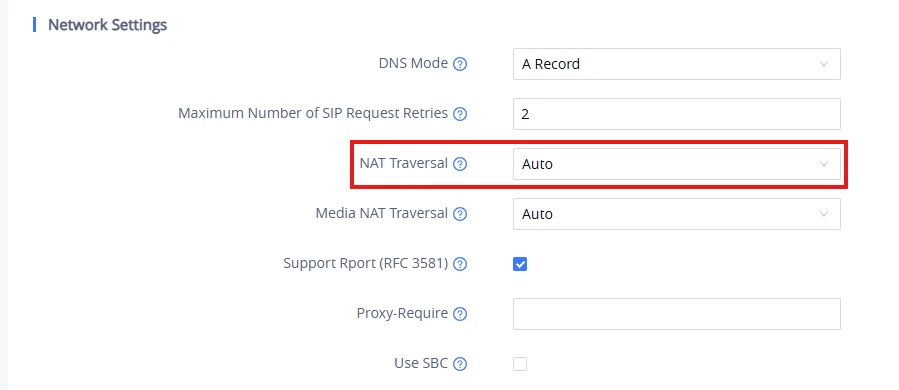
PACKET CAPTURE
The GRP260X Lite series includes an embedded network packet capture tool for real-time troubleshooting and diagnostic analysis.
Local Packet Capture
Users can follow the steps in this section to perform packet capture directly from the Web UI:
- To access the packet capture page, navigate to Maintenance → System Diagnosis → Packet Capture.
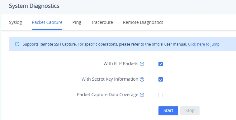
- Users can also define whether RTP packets will be captured or not from the With RTP Packets option.
- Select the With Secret Key Information checkbox to embed SSL/TLS master key secrets into the trace file, allowing Wireshark to decrypt encrypted SIP-TLS and HTTPS communications.
- Check the Packet Capture Data Coverage option to operate the capture in overwrite mode, replacing older trace data when memory fills up. Leave it unchecked to automatically stop capturing when the memory limit is reached.
- When the capture configuration is set, press the Start button to start packet capture. The Status will become RUNNING while capturing. Press the Stop button to end the capture.
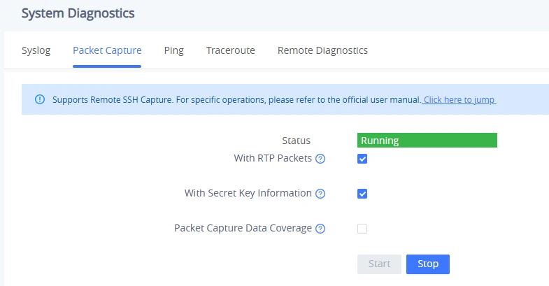
- Click the Download button to save the .pcap trace file to your PC, or click Delete to permanently clear the capture file from the device memory.
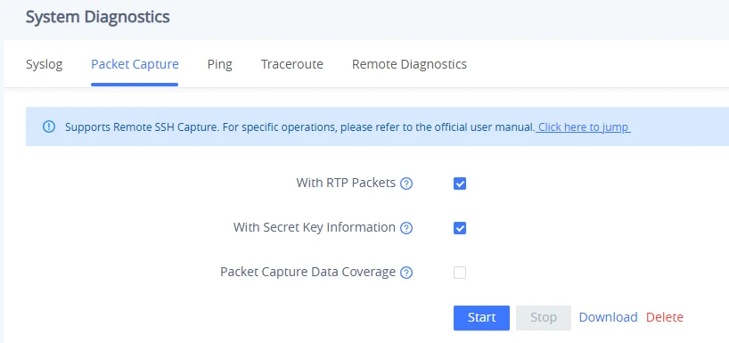
Remote SSH capture
Remote SSH capture is the process of remotely accessing and capturing network traffic on a target machine via a secure shell (SSH) connection. When configured, the Remote SSH option will allow us to capture the network traffic that is flowing through the GRP260x Lite IP phone.
This allows us to inspect the traffic, analyze it, and potentially identify any security issues or anomalies. To do this on the Wireshark network analysis tool, we will need to follow the steps below:
- Enable SSH under System settings → Security settings → SSH Access.
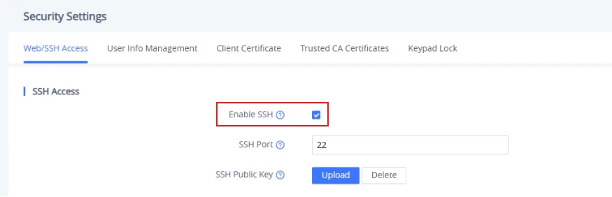
- Open Wireshark on your management PC and confirm that the sshdump and ciscodump plugins are installed.
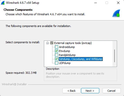
- Once Wireshark is installed with the needed components, launch the SSH remote capture configuration page by clicking the icon shown below

- In the Server tab, enter the IP address and SSH port of the GRP260x Lite IP phone.
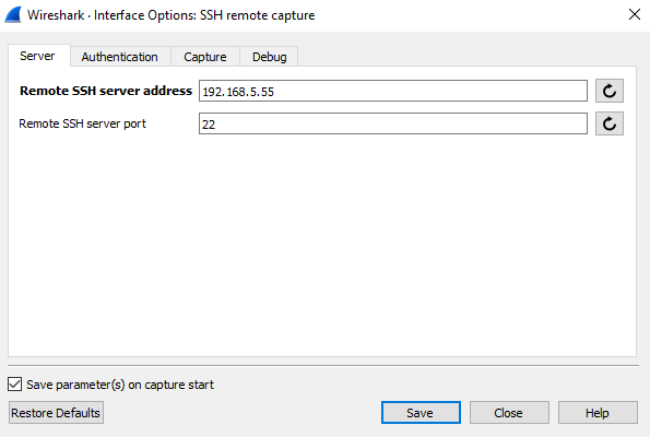
- In the Authentication tab, enter the phone’s admin credentials.
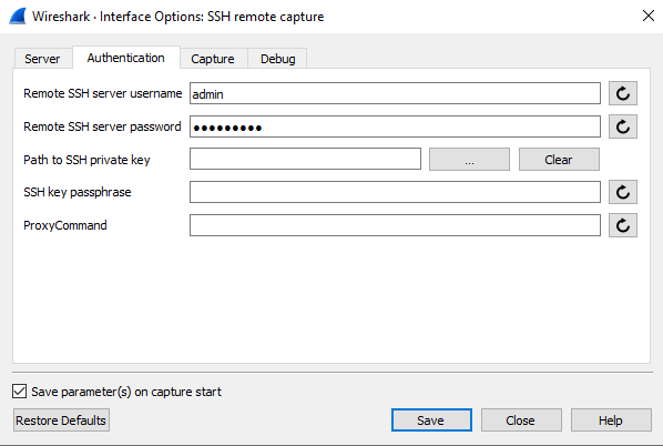
- Enter other:pcap as the remote capture command in the Capture tab.
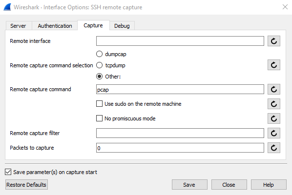
- Once the steps are followed, an “SSH remote capture” option will be displayed on the main page of Wireshark. To start capturing, click on “SSH remote capture” as shown below

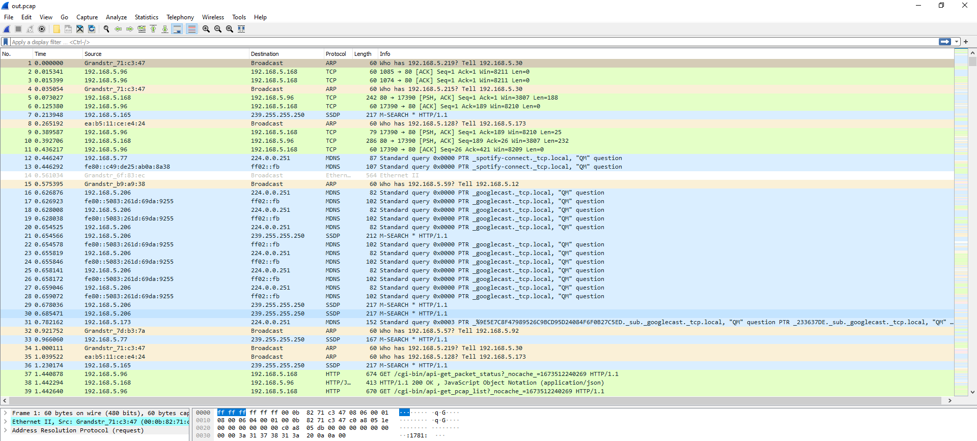
GDMS Packet Capture
Packet capture diagnostics for the GRP260x Lite phones can also be performed remotely through the Grandstream Device Management System (GDMS) cloud platform, allowing administrators to gather network traces without requiring local LAN access, SSH connections, or router port forwarding.
- Log in to your Grandstream Device Management System (GDMS) account.
- Navigate to Diagnostics → Device Diagnostics (or VoIP Device) and select your target device entry.
- Click the Start button to initiate a trace. Network captures cannot be longer than 5 minutes. The capture will stop automatically upon exceeding this limit.
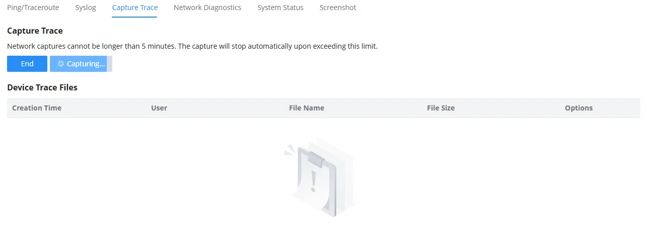
- Use the Stop button to complete the trace session, then download the generated .pcap file directly from the GDMS cloud repository.
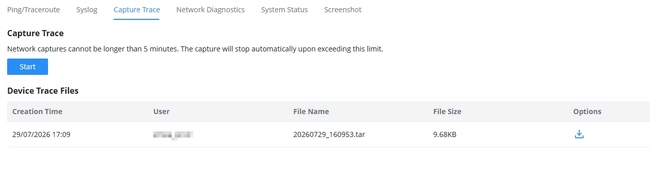
UPGRADING AND PROVISIONING
The GRP260x Lite series supports flexible, automated, and secure methods for maintaining software integrity and updating system configurations across local network or remote environments.
Unified Firmware
Grandstream GRP260x Lite IP phones utilize a unified firmware architecture, meaning a single firmware binary image is compatible across multiple models within the same product family. This standardizes IT operations and simplifies firmware management across enterprise deployments.
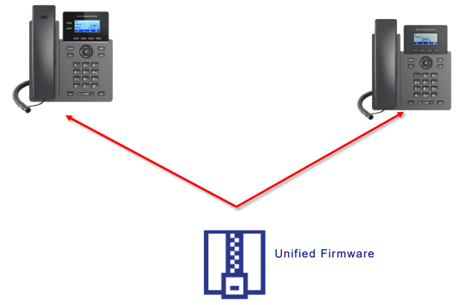
Firmware Upgrade
Firmware files can be retrieved remotely or locally over TFTP, FTP, FTPS, HTTP, or HTTPS protocols by specifying a valid IP address or Fully Qualified Domain Name (FQDN) in the Firmware Server Path configuration field. Alternatively, firmware can be uploaded directly from a local computer or managed via GDMS.
Upgrading via Web UI (Direct File Upload)
Administrators can perform a direct manual upgrade by uploading a firmware file (.bin) directly from their local computer to the device through the web interface, without the need to use a provisioning server.
- Open a web browser, log in to the phone Web UI using administrator credentials, and navigate to Maintenance → Upgrade and Provisioning.
- Locate the Upgrade via Manually Upload section and click on the Upload button.
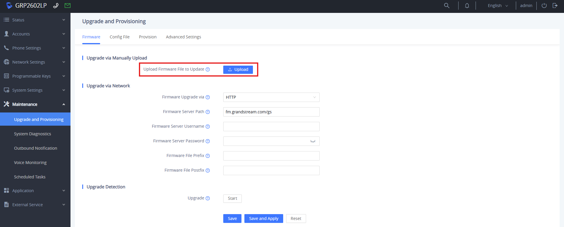
- Browse and select the firmware file stored on your local machine.
- The web UI transfers the firmware file directly to the device’s internal flash memory, after which the phone automatically validates the binary image and reboots to complete the installation.
Upgrading via Web UI (Server Path)
Administrators can configure the GRP260x Lite phone to pull firmware automatically from an external network or internet server.
- Open a web browser, log in to the phone Web UI using administrator credentials, and navigate to Maintenance → Upgrade and Provisioning.
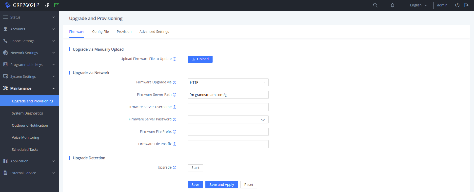
- Select the preferred protocol from the Firmware Upgrade via dropdown menu (options include TFTP, HTTP, HTTPS, FTP, or FTPS).
- Enter the server IP address or FQDN into the Firmware Server Path field.
- (Optional) If the firmware server requires HTTP/HTTPS basic authentication or FTP access, enter the valid account credentials into the Firmware Server Username and Firmware Server Password fields.
- (Optional) Use the Firmware File Prefix and Firmware File Postfix fields to filter firmware binary downloads when multiple versions reside in the same server directory.
- Click Save and Apply, then click Reboot to trigger the firmware update process.
Upgrading via GDMS
Administrators can push firmware updates remotely across single or batch devices using the Grandstream Device Management System (GDMS). GDMS gives administrators flexible control by supporting two firmware resource types:
- Public Firmware: Official firmware releases automatically synced from Grandstream’s official server repository.
- Custom Firmware: Beta or custom firmware builds uploaded manually by administrators to GDMS cloud storage (System → Resources → Firmware → Custom Firmware).
To execute a firmware upgrade through GDMS:
- Navigate to the VoIP Device page and check the box next to the target device entry (or select multiple devices for batch upgrades).
- Click the Upgrade Firmware button located on the top action bar.
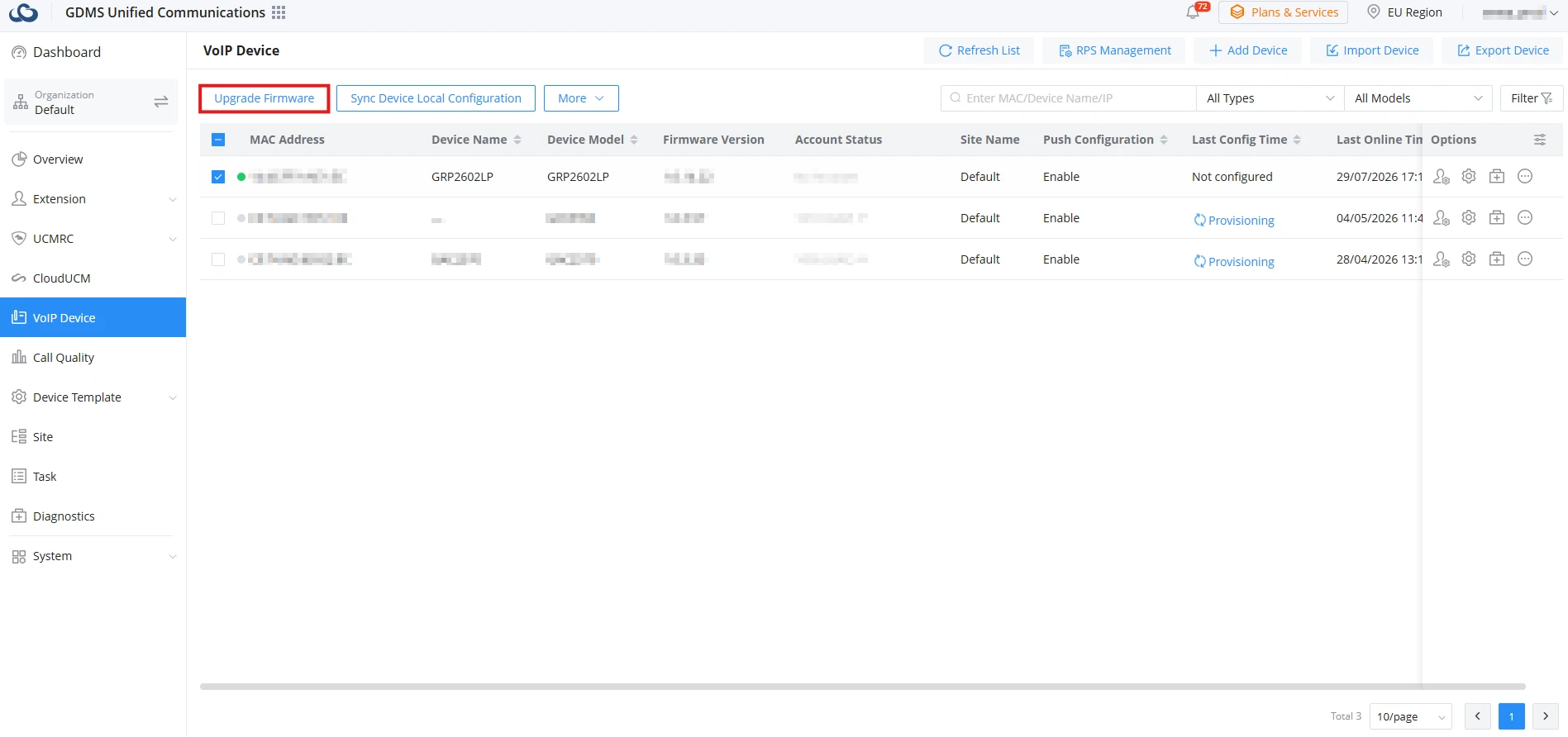
- Click the Firmware Version dropdown menu and select either an official release or a custom uploaded version.
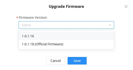
- Under Task Time, select the desired execution mode:
- Immediate: Sends the firmware upgrade command to the target devices immediately upon saving.
- Scheduled: Opens date and time fields to schedule the upgrade task to execute automatically during maintenance windows.
- Click Save to create and execute the upgrade task according to the selected schedule. Once triggered, the target devices automatically fetch the specified firmware image and reboot upon completion.
Upgrade via Keypad Menu
Users can manually trigger the device to check for available firmware updates directly from the keypad, using the server parameters previously configured in the phone’s Web UI.
- Press the MENU button on the phone keypad and navigate to Settings → Advanced Settings→ Upgrade.
- Select Upgrade to trigger an update check based on the Web UI configuration.
- When prompted, confirm with the YES softkey to check for updates and begin the upgrading process immediately.
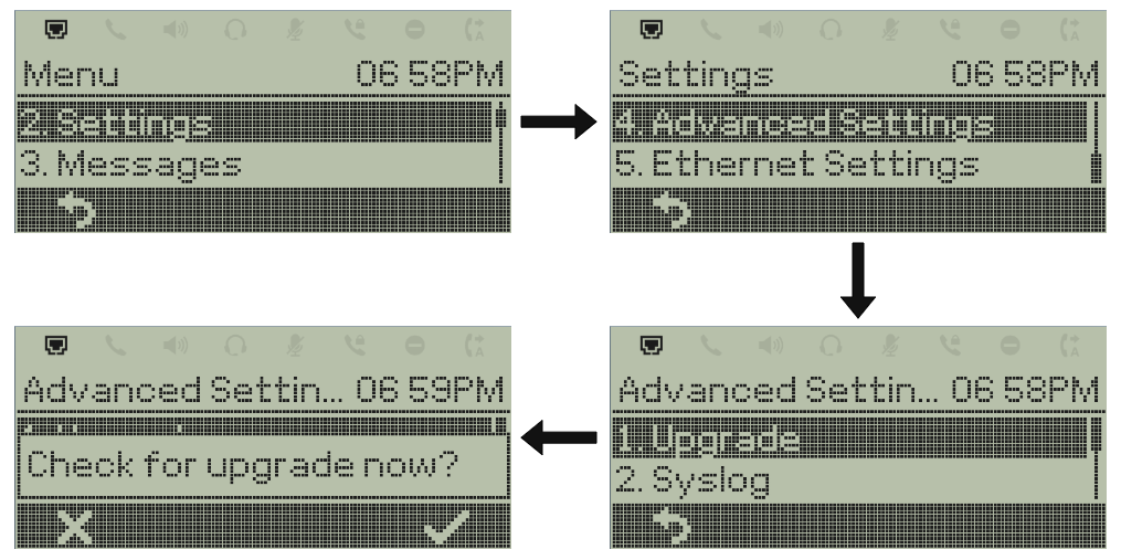
When upgrading starts, the screen will show the upgrading progress. When done, you will see the phone restart again. Please do not interrupt or power cycle the phone when the upgrading process is on.
Phone Provisioning
Configuration File Download
Grandstream SIP devices offer flexible configuration options through both the web interface and configuration files. The system supports different provisioning methods, including the ability to process multiple custom configuration files.
Devices can be configured via:
- Web interface
- Configuration files (binary or XML format) using:
- TFTP
- FTP/FTPS
- HTTP/HTTPS
- HTTPS (secure)
The “Config Server Path” is the TFTP, FTP/FTPS, or HTTP/HTTPS server path for the configuration file. It needs to be set to a valid URL, either an FQDN or an IP address format. The “Config Server Path” can be the same or different from the “Firmware Server Path”.
Configuration Parameters (P-values and Aliases)
Each web interface field corresponds to a configuration parameter using the formats:
Pfollowed by 2-5 digits (e.g.,P2for Admin Password)- Intuitive names that match web UI field names for easier management (e.g.,
users.admin.password= Admin Password - For complete parameter mapping, refer to the configuration template, which can be downloaded from Grandstream tools.
Example configurations:
The following configurations are examples for enabling SSH access on the phone.
- XML Format (using alias):
<?xml version="1.0" encoding="UTF-8"?>
<gs_provision version="1">
	<config version="2">

		<item name="security.ssh">Yes</item>

	</config>
</gs_provision>- Binary Format (using P-values):
#
P276=1
#
Configuration File Hierarchy
When booting or rebooting, GRP260x Lite series phones follow this sequence to locate configuration files:
- Primary MAC-specific XML:
cfgxxxxxxxxxxxx.xml(wherexxxxxxxxxxxxis the device’s 12-digit MAC address) - MAC-specific binary fallback:
cfgxxxxxxxxxxxx(same MAC address without file extension) - Model-specific configuration:
cfg<model>.xml(where<model>is the phone model, e.g.,cfggrp2601l.xml) - Global configuration file:
cfg.xml(applies to all devices if present) - Legacy binary configuration:
dev[MacAddress].cfg(using the device MAC address format)
No Touch Provisioning
When the configuration server responds with an HTTP 401 Unauthorized challenge during a provisioning request, the device supports automated authentication handling.
If predefined credentials exist under Maintenance → Upgrade and Provisioning → HTTP/HTTPS Username / Password, the device automatically authenticates and completes the file download.
If credentials are missing or invalid, an authentication pop-up banner displays on the phone LCD, prompting the user to manually enter the valid username and password to proceed.
REBOOT
Restarting the GRP260x Lite device clears active system memory, reapplies newly configured network and SIP settings, and forces the phone to re-establish connections with registration and provisioning servers.
The device can be restarted using any of the following methods:
Reboot via LCD Menu
Users can initiate a manual reboot directly using the physical navigation keys on the phone interface.
- On the idle screen, press the MENU button on the handset keypad.
- Navigate using the directional keys to the Reboot option.
- Confirm the reboot prompt to execute the system restart.
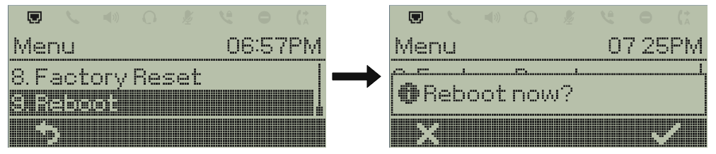
Reboot from the Web UI
Administrators can restart the phone remotely through the browser interface.
- Open a web browser, log in to the phone Web UI using administrator/user credentials.
- Click the dedicated Reboot button located at the top-right corner of the web header.

- Confirm the action when prompted. The phone will perform a system restart immediately.
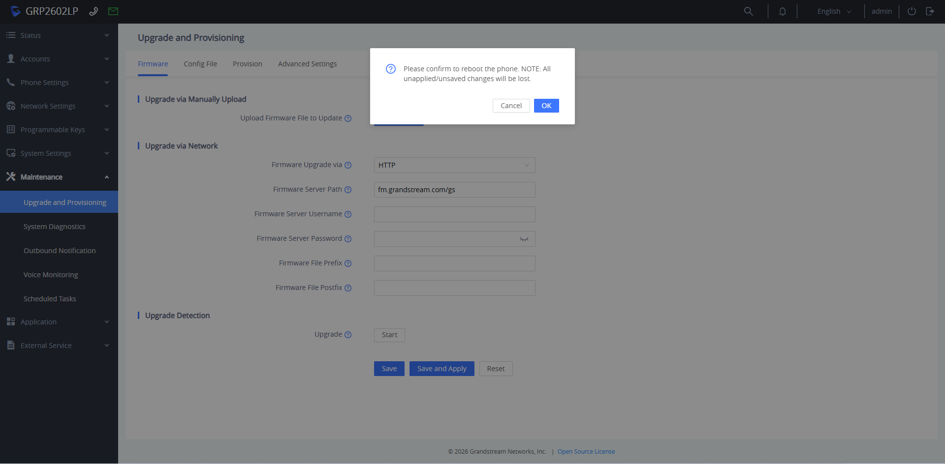
To configure automated periodic restarts for system maintenance during off-peak hours:
- Navigate to Maintenance → Scheduled Tasks, and click Add to configure a new task.
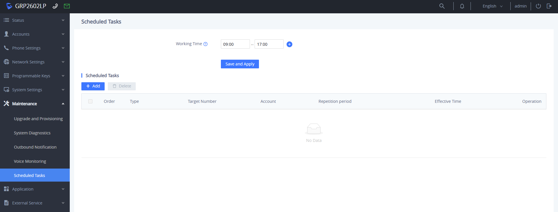
- Set Scheduled Tasks Type to Scheduled Reboot.
- Configure the Repetition period dropdown to define how often the task repeats (e.g., No repeat, Daily, or specific interval settings).
- Enter the exact execution time in the Effective Time field, and click OK to save and apply the scheduled reboot rule.
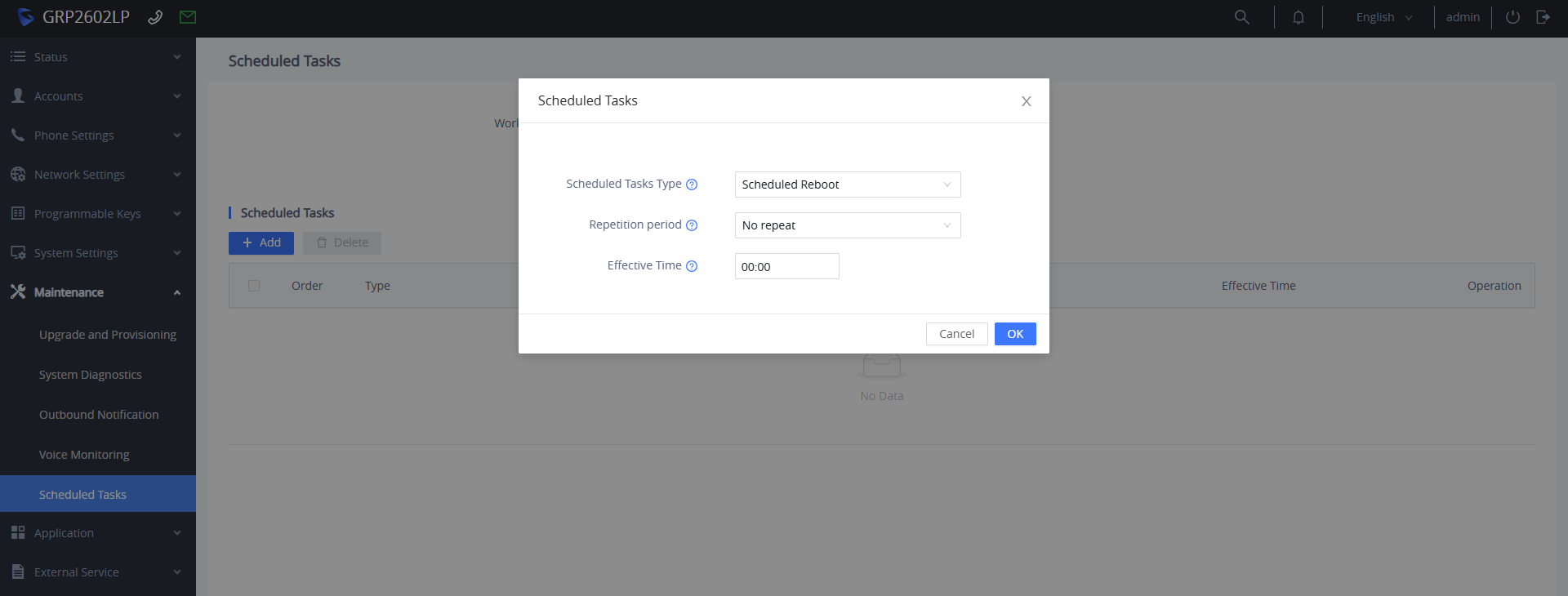
Reboot through SSH
Users can also execute a remote system reboot over SSH terminal access by following these steps:
- Ensure SSH is enabled under System Settings → Security Settings → SSH Access.
- Open an SSH client (such as PuTTY) on your PC and log in using the phone’s IP address and SSH port.
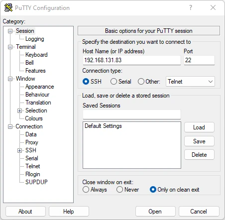
- Use your admin credentials to login.
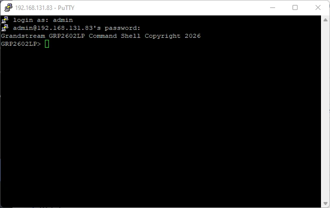
- Type the command reboot and press Enter.
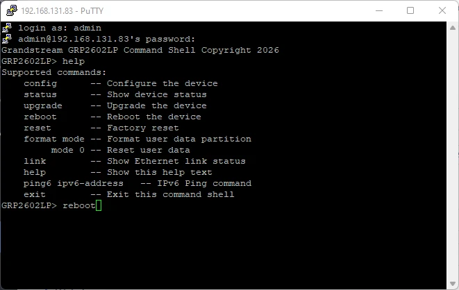
Reboot through GDMS
The GRP260x Lite series allows administrators to issue remote cloud reboots without requiring local network access or port forwarding:
- Log in to your GDMS account and navigate to VoIP Device.
- Select the check box next to the target device entry (or select multiple devices for batch reboots).
- Click the More dropdown menu and select Reboot Device.
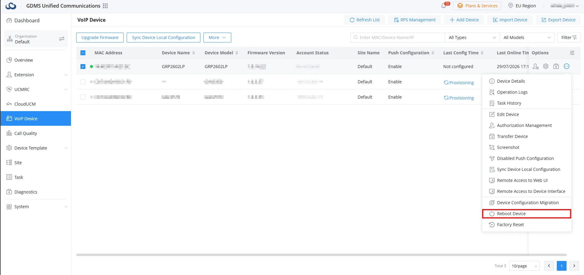
- In the pop-up window, select the preferred execution timing:
- Immediate: Sends a real-time restart command directly to the selected devices.
- Scheduled: Sets a designated date, start time, and end time to automatically execute the reboot task during non-business hours.
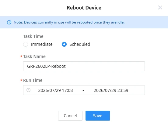
- Click Save to create the reboot task. You can monitor the progress and status of active or queued restart tasks under the Task management menu on GDMS.
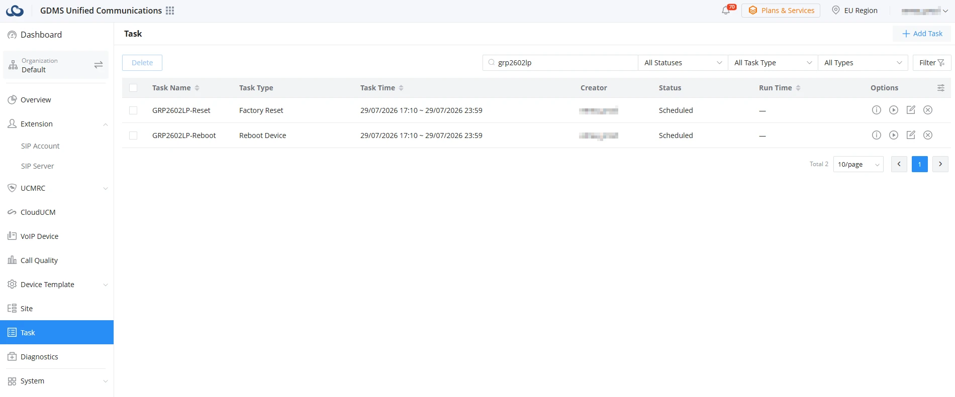
FACTORY RESET
Restoring the device to its factory default settings permanently deletes all custom configuration settings, registered SIP accounts, network rules, local call logs, and personal phonebook entries. Once executed, the phone reverts to its out-of-the-box factory configuration.
The device can be restored to factory defaults using any of the following methods:
Factory Reset via LCD Menu
Users can restore the GRP260x Lite to default settings directly on the phone screen:
- On the phone idle screen, press the MENU button to access the main menu.
- Navigate directly to the Factory Reset option using the directional keys and click on it.
- If prompted, enter the administrative password (the password is required if the keypad menu constraint mode is enabled).
- Confirm the reset by pressing the softkey. The device will erase its flash memory and automatically restart with default factory settings.
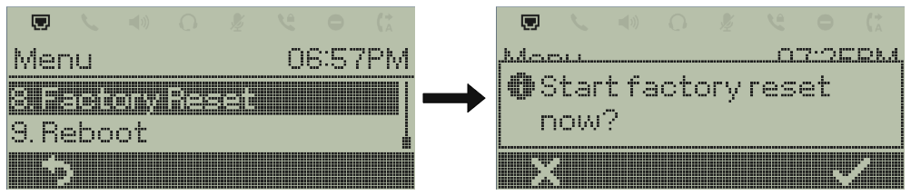
Factory Reset from the Web UI
Administrators can execute a remote factory reset through the phone’s web management interface.
- Open a web browser, log in to the phone Web UI using administrator credentials, and navigate to Upgrade and Provisioning → Advanced Settings.
- Locate the Factory Reset section and click the Start button.
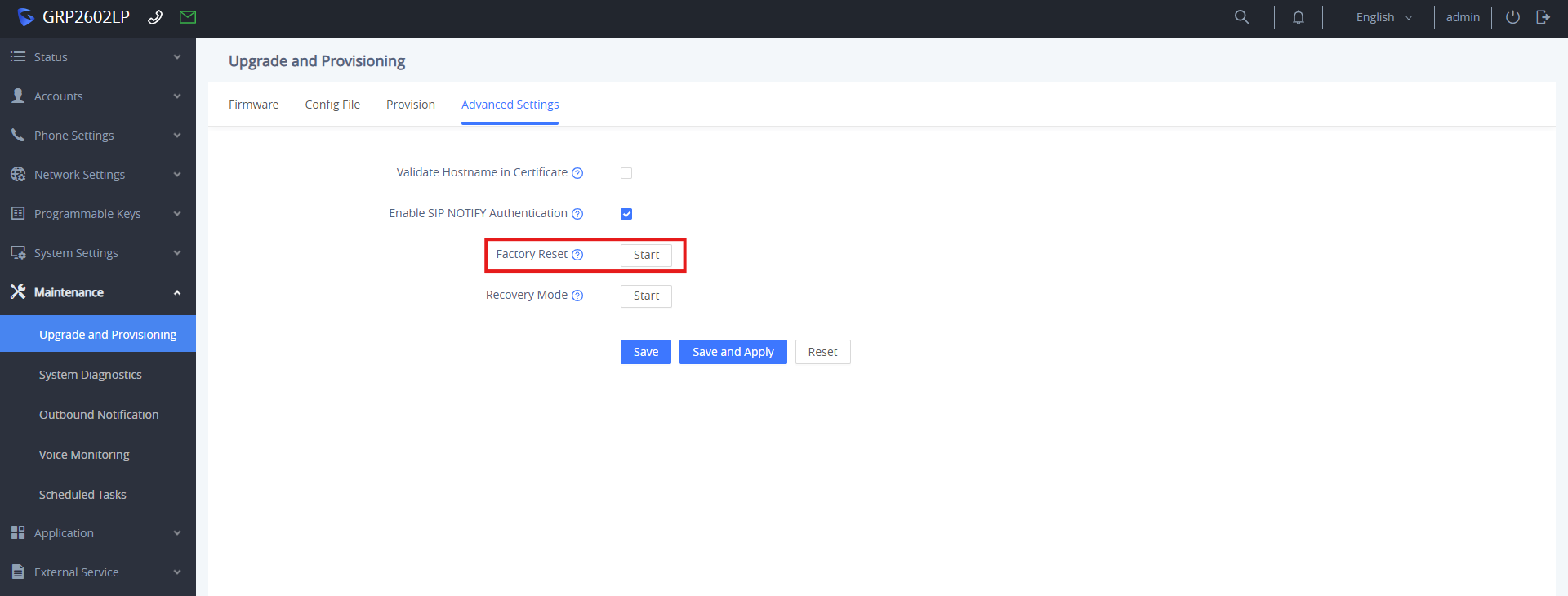
- A confirmation dialog box will pop up on the screen. Click OK to proceed.
The phone will clear its stored configuration and perform an automatic reboot.
Factory Reset via SSH
Command-line administration allows administrators to execute an immediate factory wipe over an encrypted SSH terminal connection.
- Ensure SSH is enabled under System Settings → Security Settings → SSH Access.
- Open an SSH client (such as PuTTY) on your PC and log in using the phone’s IP address, SSH port, and admin credentials.
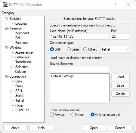
- Type the command reset and press Enter.
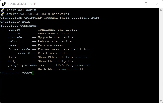
The device will receive the command, clear all configuration data from its internal memory, and reboot into its factory default state.
Factory Reset from GDMS
GDMS allows users to perform a remote factory wipe command to endpoints managed under their organization without requiring local network connectivity.
- Log in to your GDMS account and navigate to VoIP Device.
- Locate the target device entry in the table and click the check box next to it.
- Click the More dropdown menu on the top action bar and select Factory Reset.
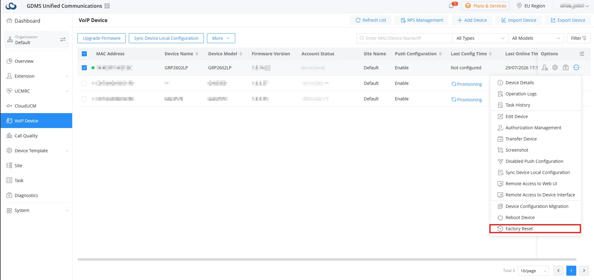
- In the pop-up window, select the preferred execution timing:
- Immediate: Sends a real-time factory reset command directly to the selected devices.
- Scheduled: Sets a designated date, start time, and end time to automatically perform the factory reset task.
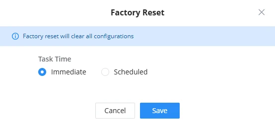
CHANGELOG
This section documents significant changes from previous versions of user manuals for GRP260X Lite. Only major new features or major document updates are listed here. Minor updates for corrections or editing are not documented here.
Firmware Version 1.0.1.29
- This is the initial version.