
WELCOME
Thank you for purchasing Grandstream GVC3212 HD Video Conferencing Device. This document introduces the LCD settings, web UI settings and advanced configurations of GVC3212. To learn the basic configuration and how to use the device, please visit http://www.grandstream.com/support to download the latest “GVC3212 User Guide”.
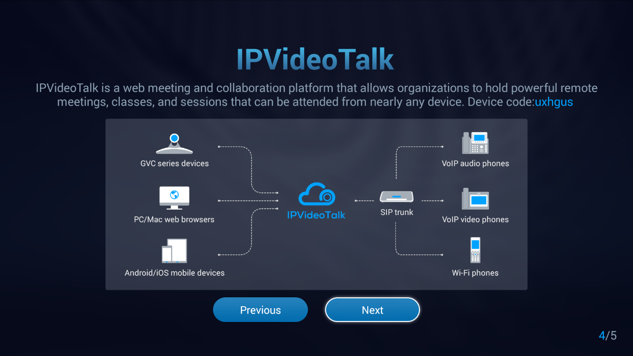
The GVC3212 is a compact and affordable HD video conferencing endpoint for TV and desktop mounting. This device pairs with Grandstream’s IPVideoTalk Meeting plans, an online conferencing platform that allows you to host meetings that can be joined on nearly any de vice including mobile, PCs, and laptops. The GVC3212 comes equipped with integrated dual microphones that offer high quality voice pickup at up to 3-meter distance, advanced echo cancellation, and sophisticated background noise suppression. It supports Miracast and Air Play for convenient wireless content screen sha ring, allowing meeting participants to share presentations, videos, or other content directly from their PC/ Mac or Android/iOS devices without tangling cables. This easy-to-use, easy-to-deploy video conferencing end point is the ideal choice for remote workers and small offices who need a price-friendly option that still pro vides the features necessary to sustain high quality video communications.
PRODUCT OVERVIEW
Table 1: GVC3212 Technical Specifications
Specification | Description |
Platform | IPVideoTalk |
Network Interface | 1x auto-sensing RJ45 10/100 Mbps Ethernet port |
Display | 1x HDMI 1.5 with support for up to 1080p video display |
Camera | Megapixel CMOS sensor, 720P@30fps |
Lens | 60° field-of-view wide angle |
Remote Control | Companion IR remote control |
Wi-Fi | Integrated dual-band Wi-Fi 802.11 a/b/g/n/ac |
Auxiliary Ports | TRS 3.5mm, 2x USB 2.0 |
Audio Codecs | Full-band Opus, wide-band G.722, G.711, AEC, ANS, AGC, Noise Shield, PLC, CNG/VAD |
Video Codecs and Capabilities | H.264 BP/MP/HP, video resolution up to 720P 30fps; Content resolution up to 720P and up to 5fps; BFCP; anti-flickering, auto focus and auto exposure |
Conference Function | Mute, call record, call waiting, auto answer, flexible dial plan, personalized ringtones and music on hold, server redundancy & fail-over |
Wireless Screen Projection | Support Miracast and AirPlay |
HD Audio | Integrated omni-directional and cardioid dual-microphones that supports 48KHz full-band voice sampling rate and 3-meter voice pickup distance with advanced acoustic echo cancellation |
Mounting Stand | Built-on adjustable stand for TV-top mounting |
QoS | Layer 2 QoS (802.1Q, 802.1p) and Layer 3 (ToS, DiffServ, MPLS) QoS |
Security | Random default password, unique certificate per device, user and administrator level passwords, MD5 and MD5-sess based authentication, 256-bit AES encrypted configuration file, TLS, SRTP, HTTPS, 802.1x media access control |
Upgrade/Provisioning | Firmware upgrade via TFTP / HTTP / HTTPS or local HTTP upload, mass provisioning using AES encrypted XML configuration file. |
Power & Green Energy Efficiency | Universal power adapter included: Input: 100-240V 50-60Hz Output: 12VDC 1A(12W) |
Temperature and Humidity | Operation: 0°C to 40°C Storage: -10°C to 60°C, Humidity: 10% to 90% Non-condensing |
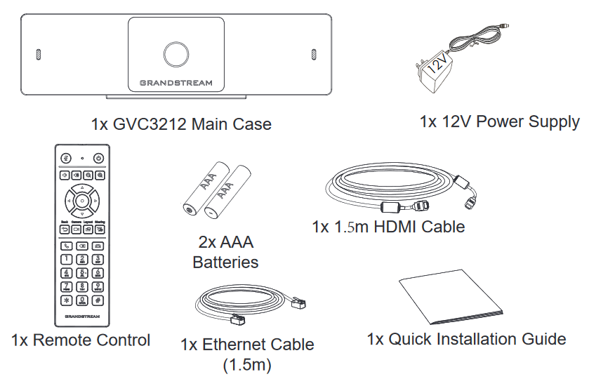
Package Content | GVC3212 device, remote control, 2x AAA batteries, universal power supply, network cable (1.5 meters), HDMI cable (1.5 meter), QIG |
Dimensions | Unit Dimensions: 130mm(L) x 35.5mm(W) x 68mm(H) |
GVC3212 complies with FCC/CE and various safety standards. GVC3212 power adapter is compliant with the UL standard. Use the universal power adapter provided with the device package only. The manufacturer’s warranty does not cover damages to the device caused by unsupported power adapters.
If GVC3212 is purchased from a reseller, please contact the company where the device is purchased for replacement, repair, or refund. If the device is purchased directly from Grandstream, please contact Grandstream Support for an RMA (Return Materials Authorization) number before the product is returned. Grandstream reserves the right to remedy warranty policy without prior notification.
INSTALLING GVC3212
Equipment Package Content
GVC3212 package contains the following items:
Connecting GVC3212
Please follow the steps below to connect the GVC3212:
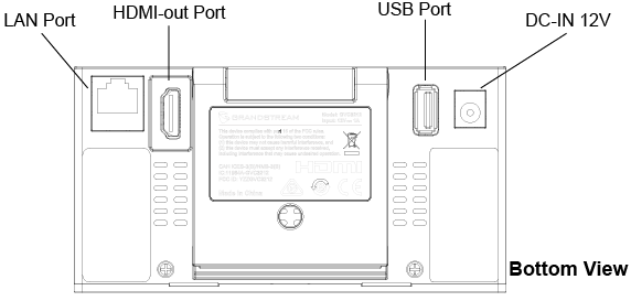
- Connect the LAN port of the GVC3212 to the RJ-45 socket of a hub/switch or a router (LAN side of the router) using the Ethernet cable.
- Connect the HDMI-out port of the GVC3212 to the HDMI port of the main display device (e.g., TV) using the HDMI cable.
- Connect the 12V DC output plug to the power jack on the GVC and then plug the power adapter into an electrical outlet.
- The display device (e.g., TV) will show the idle HOME screen with IP address on the top status bar.
- (Optional) Connect USB accessory (e.g., mouse, keyboard, USB flash drive etc.) to the USB port.
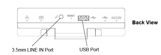
- Use the Line-In Port to connect a microphone (External audio input device).
GVC3212 Ports Description
|
Name |
Description |
|
3.5 mm Line IN |
Connect an external Microphone |
|
2 x USB Ports |
Connect to USB device (External storage, mouse…) |
|
LAN Port |
Connect to local network using RJ-45 cable |
|
HDMI OUT Port |
Connect the HDMI display devices. |
|
Power Interface |
Connect to power adapter. The arrow indicator on the power adapter should face upwards when the power adapter is plugged in. |
SETUP WIZARD
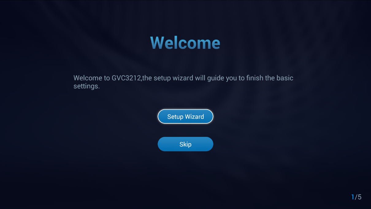
On first use or after setting the unit to factory reset, the GVC3212 offers setup wizard tool that will guide users through setting up the basic settings. Users can Skip it and configure the unit later.
Users can follow the steps using the remote control to setup fields, skip, return, or confirm the action.
Setup wizard tool is useful to lead users to check and configure the GVC3212 settings such as language, accounts, interface status and etc. Press on Setup Wizard to begin.
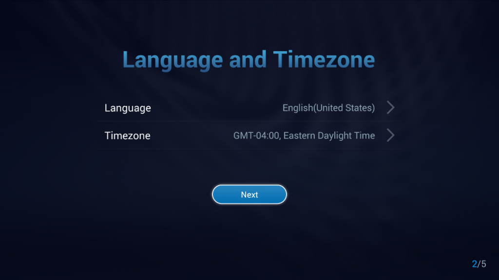
- Set display Language and the Time Zone:
2. Network Settings:
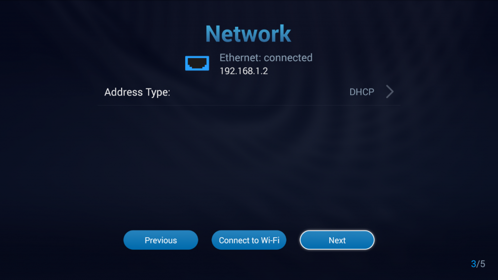
- Users can configure the Ethernet settings and set the address type as DHCP, Static IP or configure PPPoE account.
- Users can choose Wi-Fi Connection instead by pressing on Connect to Wi-Fi and connect to an available SSIDs.
3. Introduction to IPVideoTalk Service:
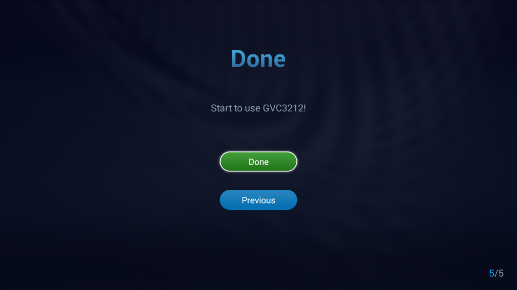
4. Completing the Setup Wizard:
GETTING TO KNOW GVC3212
Remote Control
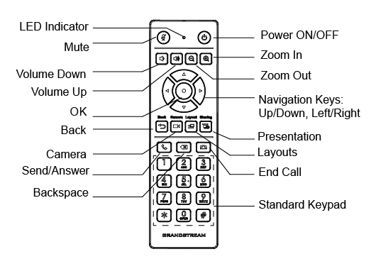
Table 3: GVC3212 Remote Control Keys
|
Icon |
Name |
Explanation |
|
1, 2, 3, 4…9 |
Digital Keys |
Input number 1-9 and letters. The letter input using digital keys will not be displayed as letter, but it can be used to search for contacts in Call interface. For example, typing 5 (JKL), 6 (MNO), 4 (GHI), 6 (MNO) can look for John if it exists in GVC3212 contacts list. |
 |
Camera |
Enable/Disable sharing local camera feed. |
 |
Layout |
Switch screen layout in conference. |
 |
Mute/DND |
Mute GVC3212 in conference. |
 |
Sharing |
Enable/Disable presentation function to send presentation to all members in the conference. |
 |
Send/Answer a call |
|
 |
End Call |
Hang up the conference. |
 |
Backspace |
Press the key to delete input characters. |
 |
Navigation Keys: Up/Down/Left/Right/OK |
|
 |
Power On/Off |
LCD prompt shows the following three options after pressing this key:
When the power button is pressed second time, the pop-up window will be closed. |
 |
Back |
Press the key to go back to the previous screen or exit the current screen. |
 |
Volume Down |
Turn down the device volume. |
 |
Volume Up |
Turn up the device volume. |
 |
Zoom In |
Zoom in screen. |
 |
Zoom Out |
Zoom out screen or adjust distant focus. |
Using the Remote Control
GVC3212 remote control is connected to GVC3212 via infrared connection. Before using the remote control, please make sure that 2x AAA batteries are correctly installed on the back of the remote control.
Infrared signals are automatically used to connect the remote control to GVC3212. Users need to
keep the two devices in front of each other without any substantial obstruction in between. The connected remote control’s LED will light up in green whenever the user presses a key.
If the remote control fails to connect to GVC3212, please follow the steps below to troubleshoot:
• Check the battery polarity when placed into the battery case. Make sure the batteries are placed in the
correct direction in the remote control.
• Check the battery power.
If GVC3210 remote control still does not work with the diagnosis above, please try another remote control
or contact the device provider.
Using Mouse & Keyboard
When the USB mouse is plugged into GVC3212, users could make the following operations with the mouse.
- Single click the left key of the USB mouse to perform the following operations:
- Access menu
- Check in the checkbox or enable/disable an option
- Bring up the drop-down list when clicking on a combo box
- Switch input methods in the input box, tap on the corresponding buttons on the soft keyboard to input characters
- Single press the left key to tap
 on the soft keyboard can switch to “Always use upper case” in English input method.
 - Single click the right key of the USB mouse to exit the current displayed menu. It will go back to the previous menu without saving the configurations.
 on the soft keyboard can switch to “Always use upper case” in English input method.
Using the LED Indicator
GVC3212 LED indicator is located next to the OLED. It can be used to notify the users with current status of the device. Please refer to the status description below.
Table 4: GVC3212 LED Indicator Status Descriptions
|
LED Indicator Status |
Descriptions |
|
Solid Red |
Booting. |
|
Solid Green |
Standby (Sleep Mode) |
|
OFF |
Power off |
Status Icons
GVC3212 status icons are displayed on the right side of top status bar on GVC3212 LCD display device.
Table 5: GVC3212 Status Icons Descriptions
|
Icon |
Descriptions |
 |
Ethernet is connected |
 |
IPVideoTalk account registered |
 |
Wi-Fi Connected |
 |
External USB device connected |
 |
Wireless Display enabled |
 |
DND Enabled |
Using the Onscreen Keyboard
English Keyboard
This is the default keyboard on GVC3212. The English keyboard supports multiple languages input methods. See figure below:
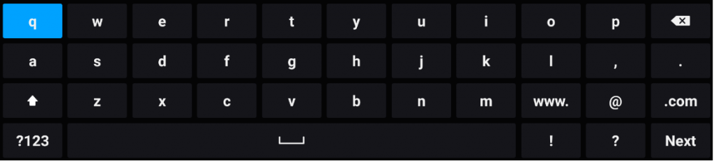
Notes: Tap on  to switch Caps Lock:
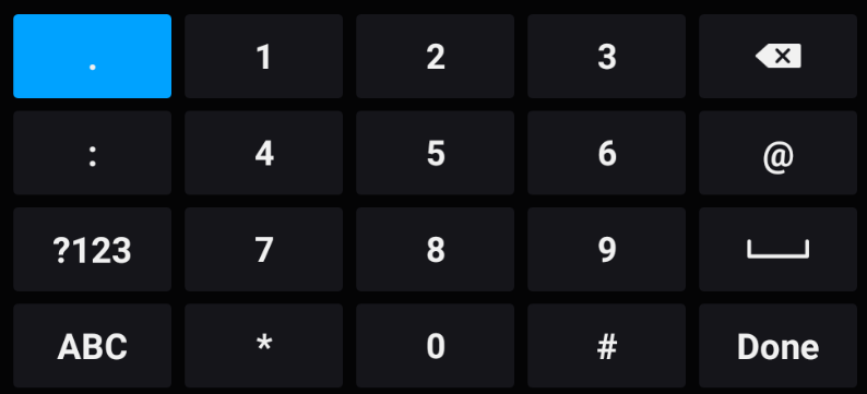
Numbers and Symbols
To input numbers and symbols, tap on button  on the default keyboard to switch to numbers/symbols.
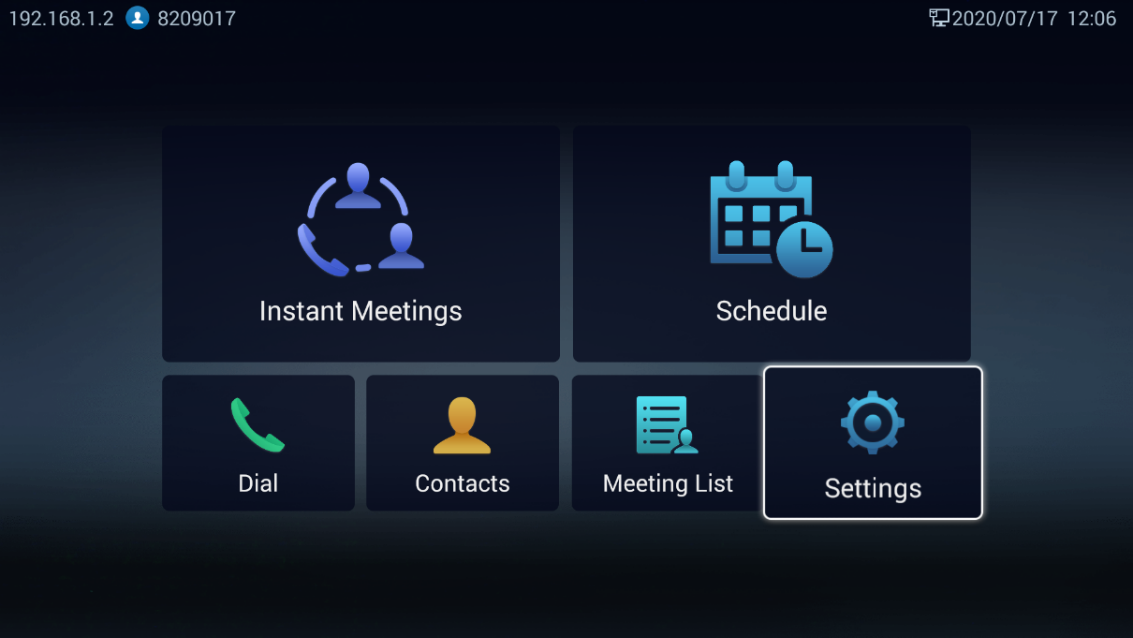
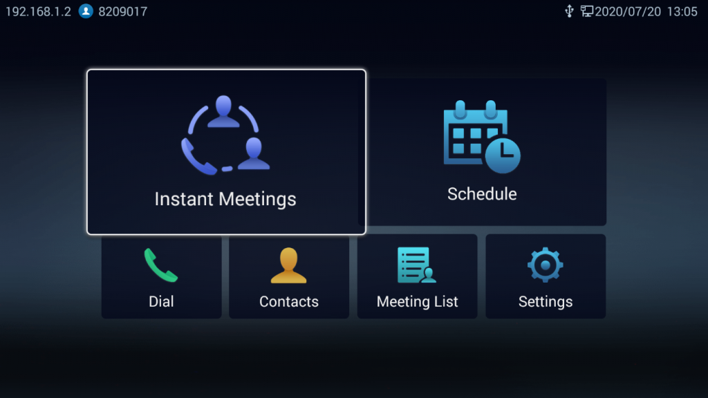
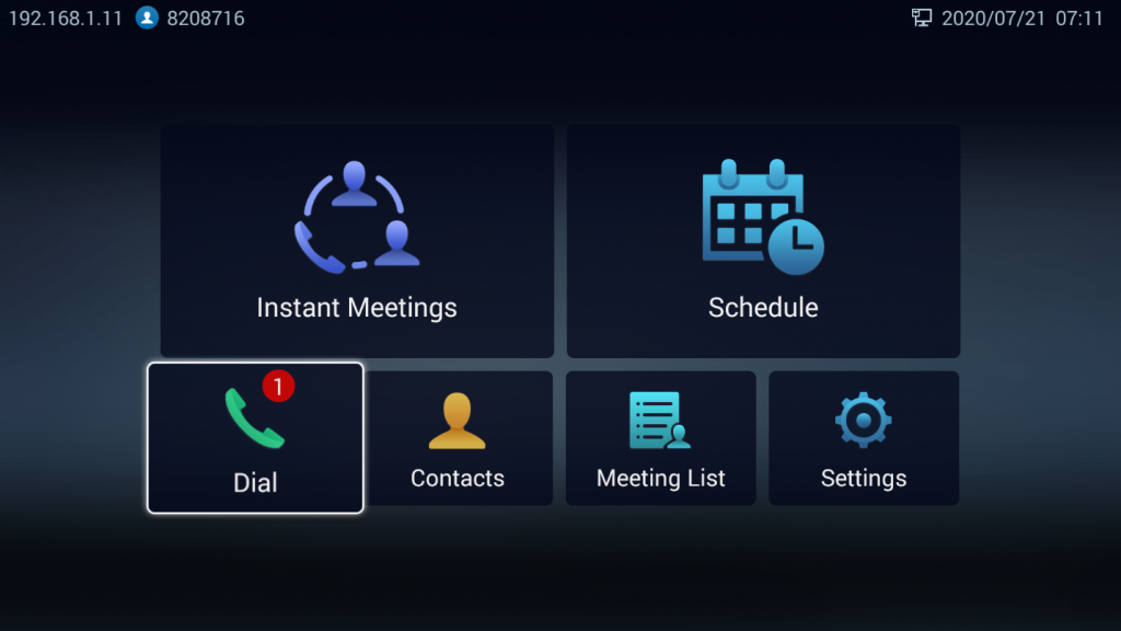
Home Screen
GVC3212 Home screen displays the icons for users to easily access Call screen, Instant messages, Contacts list, Conference List, Settings, Schedule. Press the navigation keys on the GVC3212 remote control to select an option.
GVC3212 Menu
Every menu opens a list of options. Press Arrow keys to navigate to the menu option you require. Then press “OK” to access further options or confirm the setting displayed. To go to the previous menu item, press  “Back”.
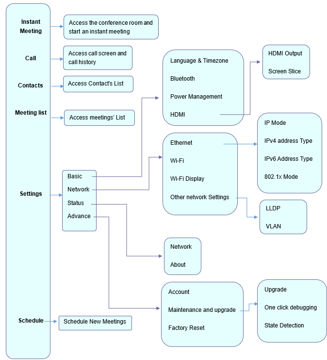
GVC3212 LCD Settings
Basic Settings
Users can configure Language & Time zone, Power Management, and HDMI Settings from the GVC3212 LCD Menu 🡪 Settings 🡪 Basic Settings.
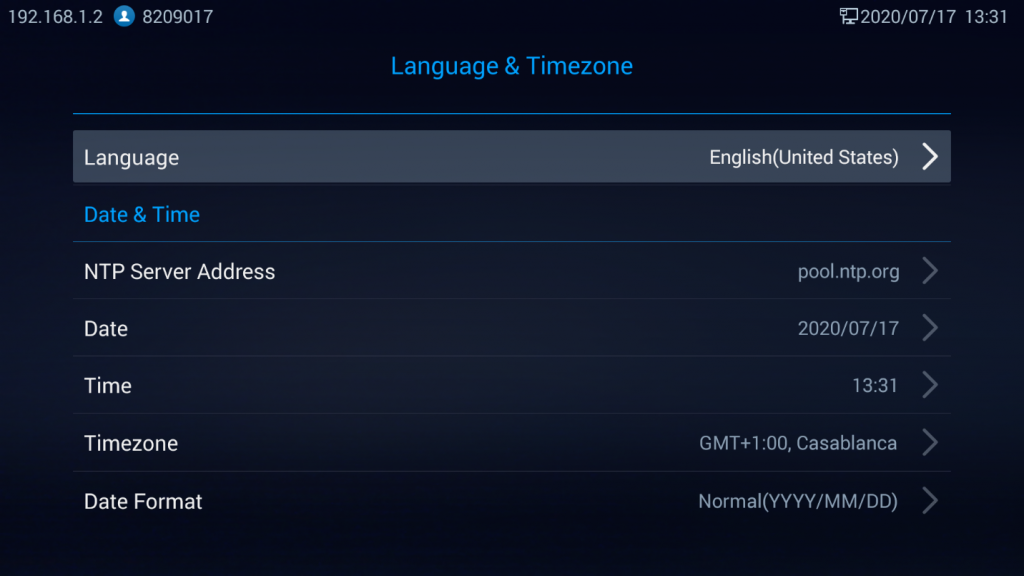
Language & Timezone
On this section, Users could choose the display language, configure proper date, and time settings such as NTP server, Date & Time format, Time zone.
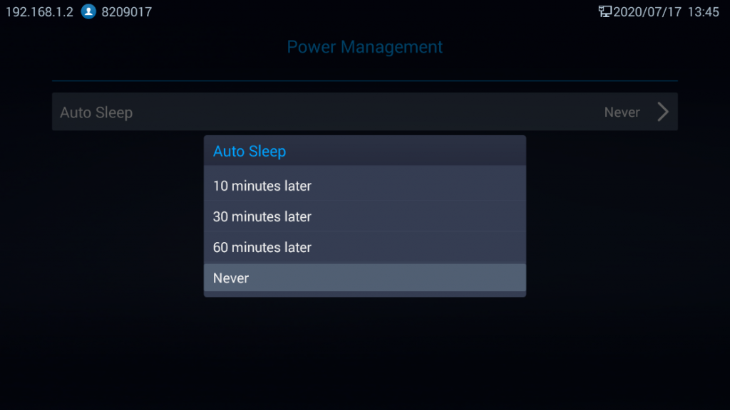
Power Management
Users could configure Auto sleep setting as a power management technique by pressing on OK button then choosing the period after which the unit auto sleeps. This setting can be disabled by setting it to never.
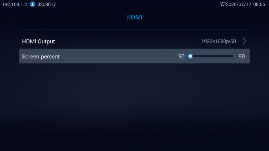
HDMI
Users could customize HDMI output display by configuring resolution settings and Screen Slice feature.
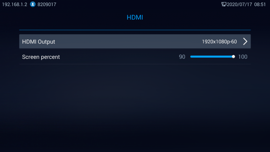
- HDMI Output: Sets HDMI out resolution. Up to 1080p supported, default is 1080p-60 fps (depending on TV resolution).
- Screen slice: This feature allows users to either enlarge the GVC3212’s output display size to match the full size of the output screen or compress the display according to users’ preferences (Minimum is 90%). Users can use Right/Left arrows to adjust the display:
Network Settings
GVC3212 supports a variety of network connections (Ethernet, Wi-Fi) in addition to Wi-Fi Display feature that is used for screen stream mirroring of other devices in the GVC3212 via Wi-Fi.
Ethernet
If the user would like to use Ethernet connection for network access, please plug the Ethernet cable into the LAN port on the back of GVC3212. Ethernet connection is turned on as DHCP by default on both IPv4 and IPv6 protocols. To configure Ethernet settings on GVC3212, go to LCD Menu 🡺 Settings 🡺 Network 🡺 Ethernet.
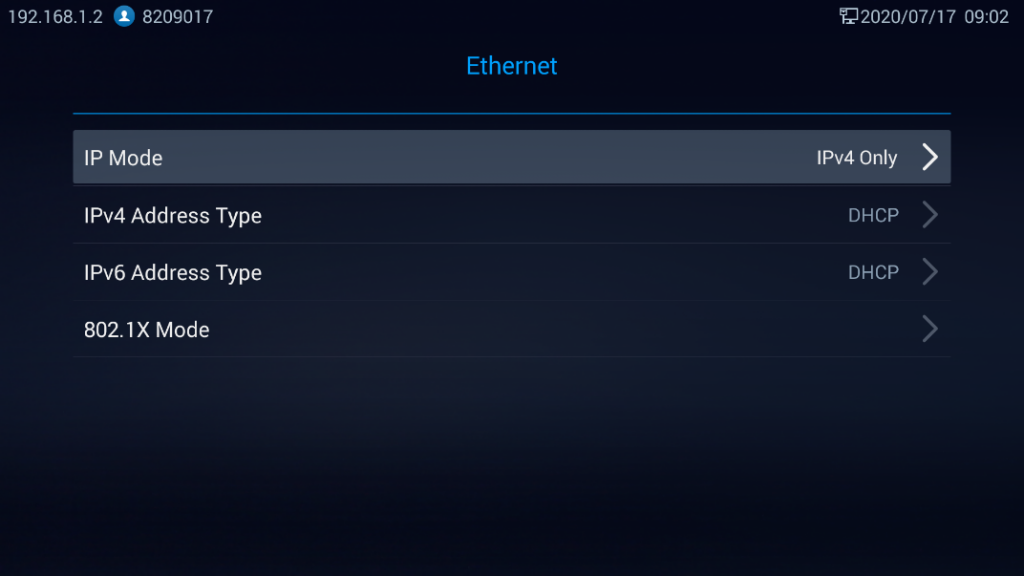
The GVC3212 offers the possibility to prioritize a protocol over another by setting Preferred Internet protocol to IPv4 or IPv6.
- Using IPv4:
To configure the GVC3212 using IPv4 protocol, follow the below steps:
- Plug the Ethernet cable into the LAN port on the back of GVC3212.
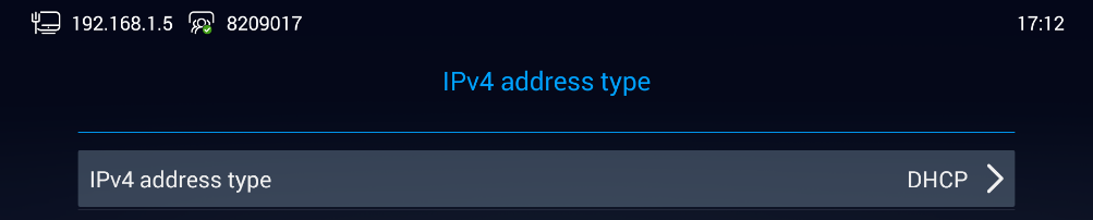
- Go to LCD menu 🡺 Settings 🡺 Network 🡺 Ethernet 🡺 IPv4 Address Type.
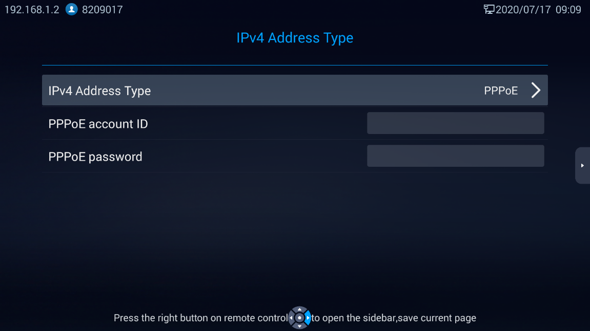
- Tap on “IPv4 Address Type” to select DHCP, Static IP or PPPoE as the address type.
- For DHCP, save the setting and GVC3212 should be able to get IP address from the DHCP server in the network.
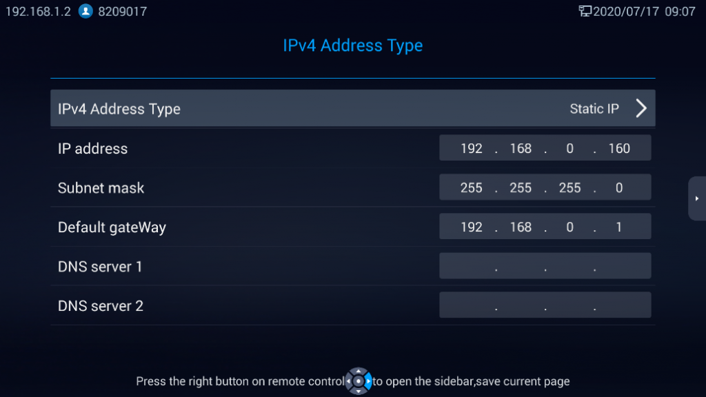
- For static IP, Press on IPv4 Address Type and select Static IP. Enter IP Address, Subnet Mask, Default Gateway, DNS Server, and Alternative DNS server for GVC3212 to correctly connect to the network.
- For PPPoE, enter PPPoE account ID and password so that GVC3212 can get IP address from the PPPoE server.
- Using IPv6:
To configure the GVC3212 using IPv6 protocol, follow the below steps:
1. Plug the Ethernet cable into the LAN port on the back of the GVC3212
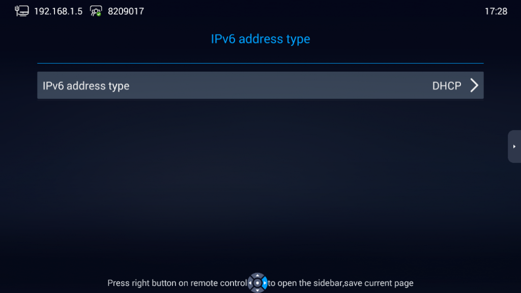
2. Go to LCD menu 🡺 Settings 🡺 Network 🡺 Ethernet 🡺 IPv6 Address Type.
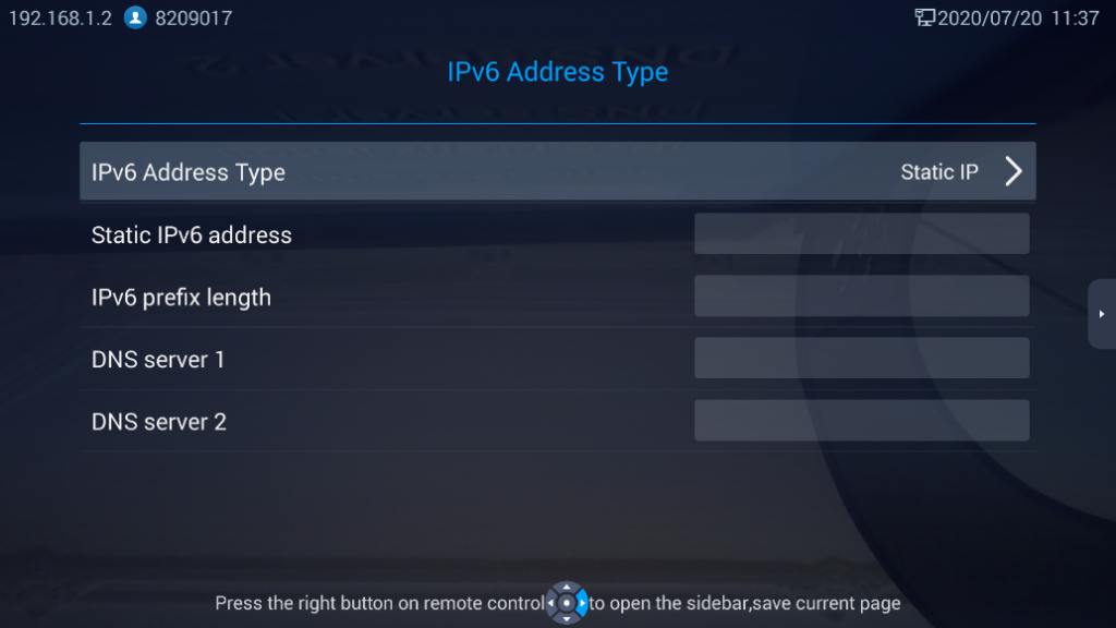
3. Tap “Address Type” to select DHCP or Static IP as the address type.
- For DHCP, save the setting and GVC3212 should be able to get IP address from the DHCP server in the network.
- For static IP, configure IPv6 address, DNS server 1, DNS server 2 and Preferred DNS server, enter the IPv6 address in the format of 2001:db8:1:2::3.
- 802.1X Mode:
Users can configure 802.1x settings under Settings 🡺 Network 🡺 Ethernet 🡺 802.1x Mode. By default, 802.1x is disabled. Users can enable it by setting 802.1x mode to “EAP-MD5”, “EAP-TLS5” or “EAP-PEAP”. Once it is enabled, the user will be required to enter the identity and password to be authenticated in the network.
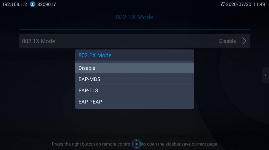
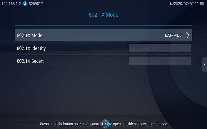
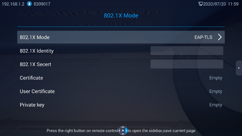
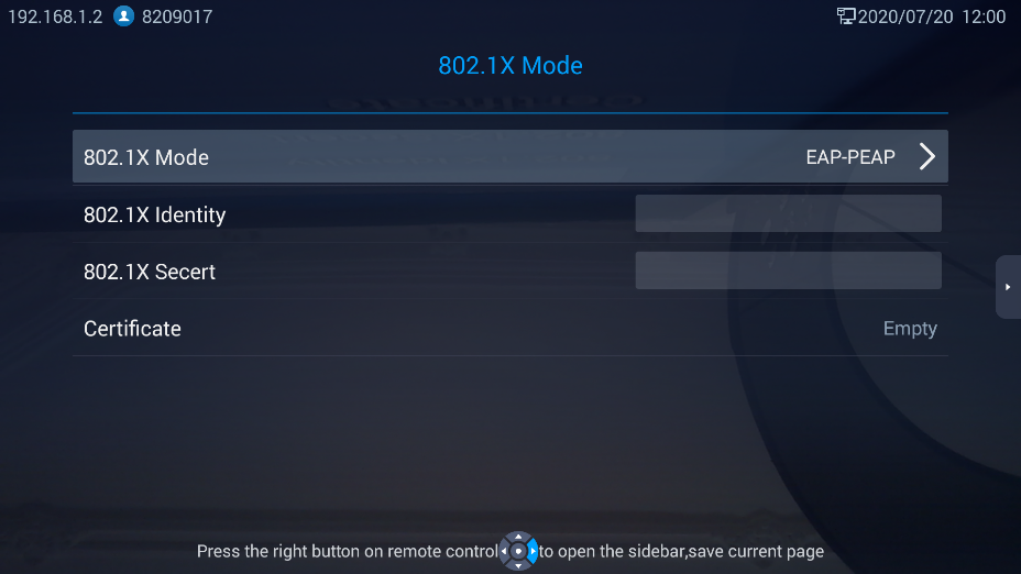
Table 6: GVC3212 802.1X Mode Parameters
|
Parameters |
Descriptions |
|
802.1x Mode |
Allows the user to enable/disable 802.1x and configure 802.1x mode. The default setting is disabled. |
|
Identity |
Enter the identity information for 802.1x mode. |
|
802.1X Secret |
Enter the password for 802.1x mode. |
|
CA Certificate |
Upload the ca certificate for 802.1x mode. |
|
Client Certificate |
Upload the client certificate for 802.1x mode. |
|
Private Key |
Upload the private key for 802.1x mode. |
Wi-Fi
Users could enable and configure Wi-Fi Settings from Settings 🡺 Network 🡺 Wi-Fi
- Enable/Disable Wi-Fi:
Once Wi-Fi is turned on (Enable), GVC3212 will automatically start the scanning within the range. A list of Wi-Fi networks will be displayed as scanning result. Tap on the SSID and enter the correct password information to connect to the selected Wi-Fi network.
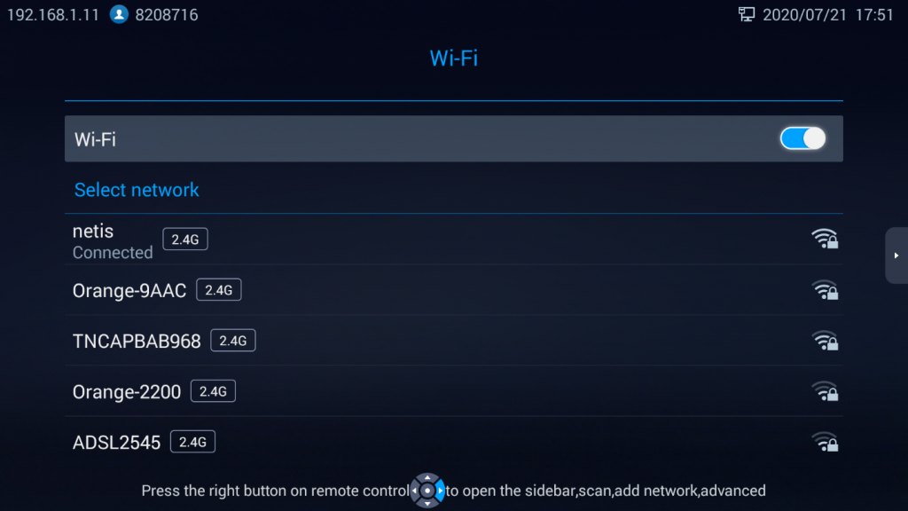
By pressing on the right arrow key on the remote control, Users can Scan available networks, Add network, or access Advanced network setting.
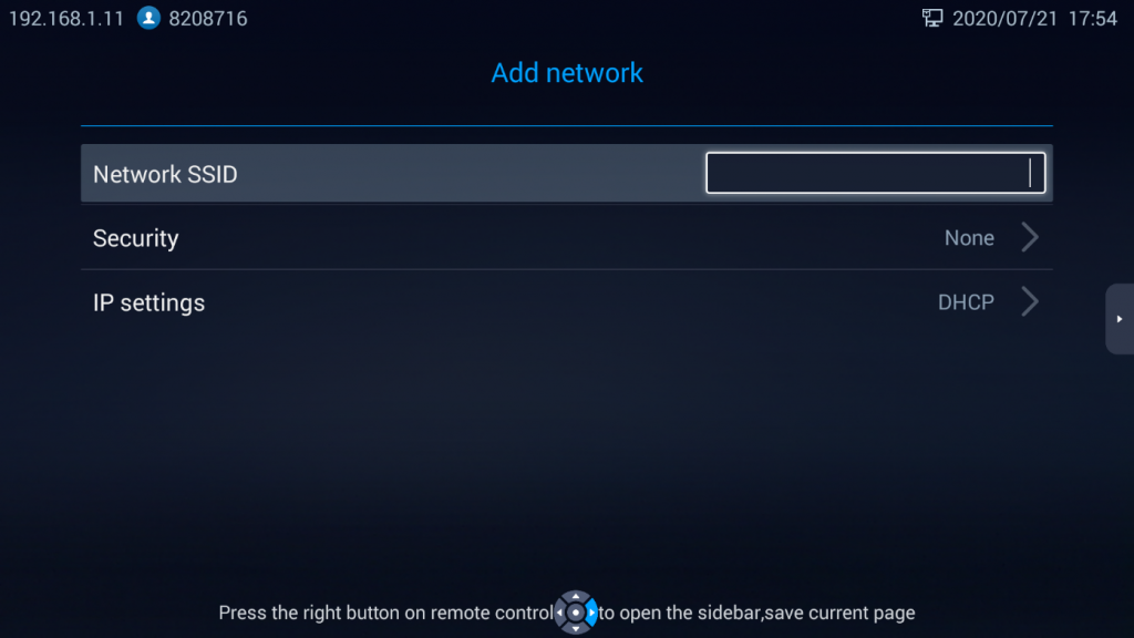
- Add Network:
User can press on Add Network to add a hidden network info:
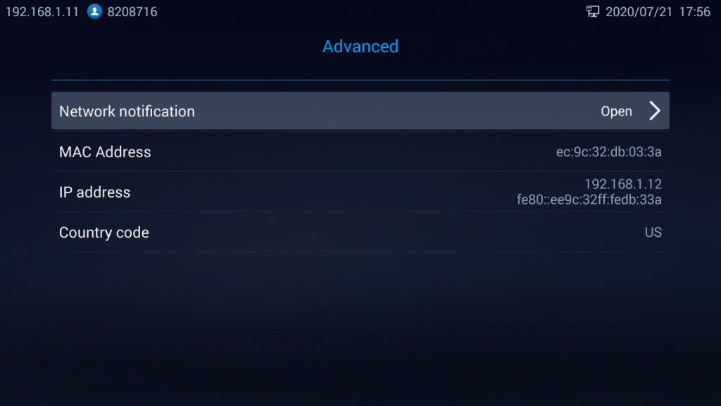
- Advanced:
On this page, customers could Enable/Disable Network Notification, check Network card’s MAC address, IP address and country code.
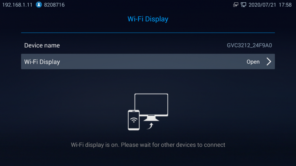
Wi-Fi Display
Wi-Fi Display feature is used for screen stream mirroring of other devices in the GVC3212 via Wi-Fi. Users need to enable Wi-Fi as a first step and then turn Wi-Fi Display Feature On to connect to other devices via Wi-Fi:
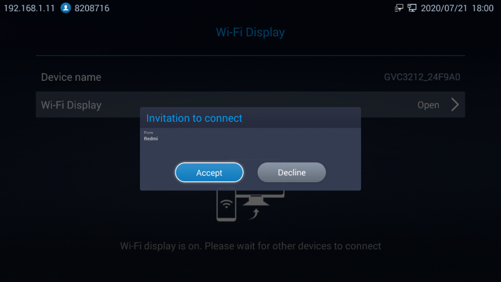
Enable Wireless display on the device you want to cast its screen, the phone will show the GVC3212 in the available devices list. The wireless connection will start immediately after accepting the invitation on the GVC3212.
LLDP and VLAN Settings
Access GVC3212 home screen, go to Settings 🡺 Network 🡺 Other Network Settings 🡺 to configure LLDP and VLAN settings on GVC3212.
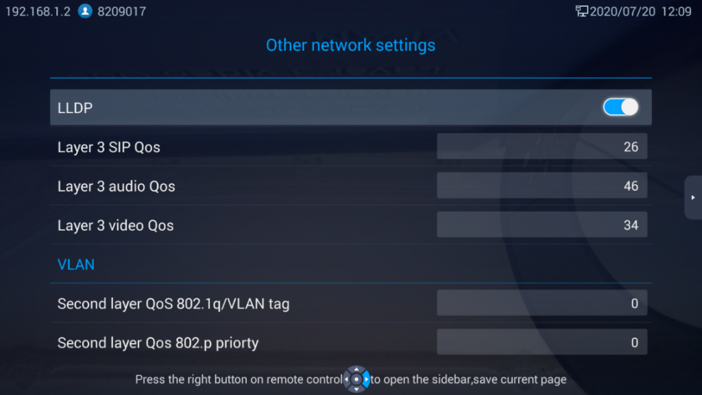
Table 7: GVC3212 LLDP Configuration Parameters
|
Parameters |
Descriptions |
|
LLDP | |
|
LLDP |
Enable or disable LLDP. The default setting is “Open”. |
|
Layer 3 SIP QoS |
This field defines the layer 3 QoS parameter for SIP packets. It is the value used for IP Precedence, Diff-Serv or MPLS. The default value is 26. |
|
Layer 3 Audio QoS |
This field defines the layer 3 QoS parameter for audio packets. It is the value used for IP Precedence, Diff-Serv or MPLS. The default value is 46. |
|
Layer 3 Video QoS |
This field defines the layer 3 QoS parameter for video packets. It is the value used for IP Precedence, Diff-Serv or MPLS. The default value is 34. |
|
VLAN | |
|
Second layer QoS 802.1q/VLAN Tag |
Assigns the VLAN Tag of the Layer 2 QoS packets for LAN port. The default value is 0. Note: Please do not change the setting before understanding the VLAN’s settings or consulting with the network administrator. Otherwise, the device might not be able to get the correct IP address. |
|
Second layer QoS 802.1p Priority |
Assigns the priority value of the Layer 2 QoS packets. The default value is 0. |
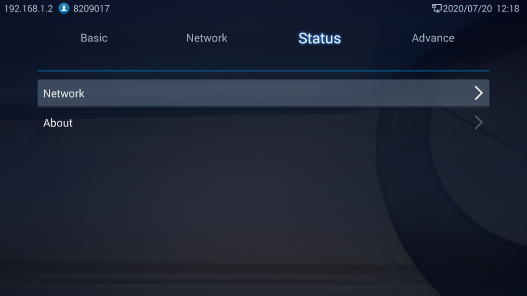
Status
Users could check the Network, Software and Hardware status by accessing LCD Menu 🡪 Settings -> Status.
Advanced Settings
IPVideoTalk Account
GVC3212 comes with a built-in IPVideoTalk account. The IPVideoTalk Account settings can be configured from LCD Menu 🡪 Settings 🡪 Advance 🡪 Account. The following figure shows the IPVideoTalk account registered successfully (account icon is blue with IPVideoTalk ID displayed):

On Account page, users can configure their IPVideoTalk Settings such as the Display name, Enable/Disable Auto answer, Set IPVideoTalk Server address and check their registered IPVideoTalk related details and current Plan information.
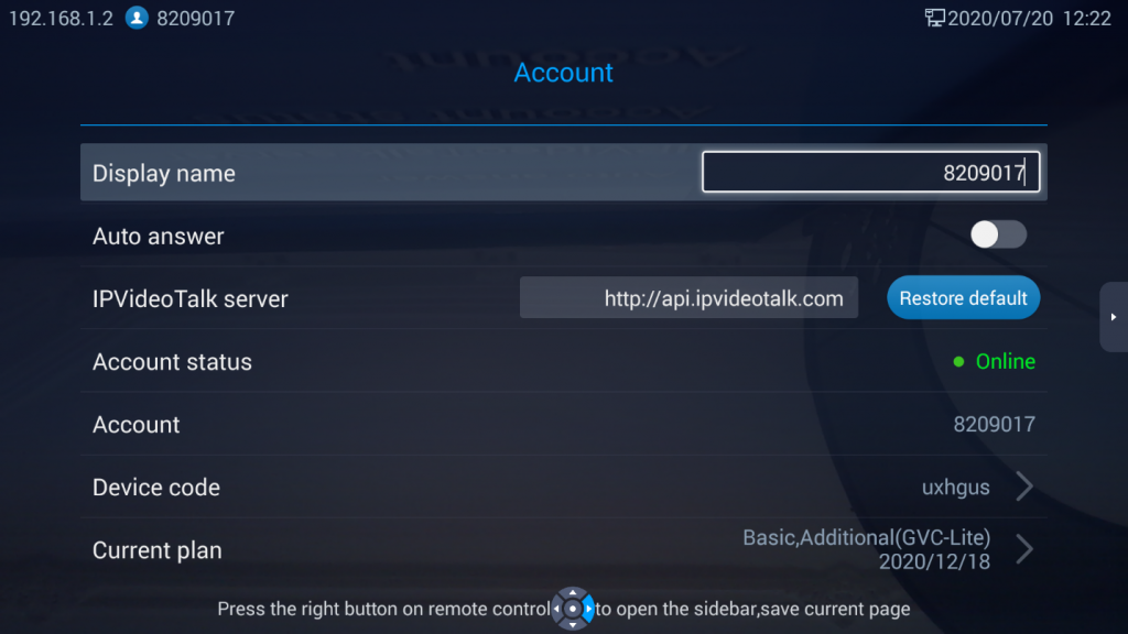
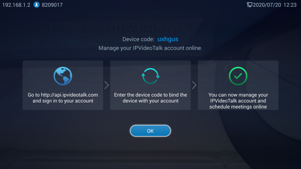
As the screenshot above shows, users could check and click on “Device code” This unique code is used to link your GVC3212 to an IPVideoTalk Account to manage and schedule meetings from there.
Maintenance and Upgrade
- UPGRADE Settings:
Users can configure firmware upgrade and configuration files download settings from LCD Menu 🡪 Settings -> Advance 🡪 Maintenance and Upgrade 🡪 Upgrade. On this section, users could check if there is a new firmware version uploaded to the firmware server path configured by pressing on “Version Detection” option, or could go through with configuring the upgrade settings by pressing on “Settings”:
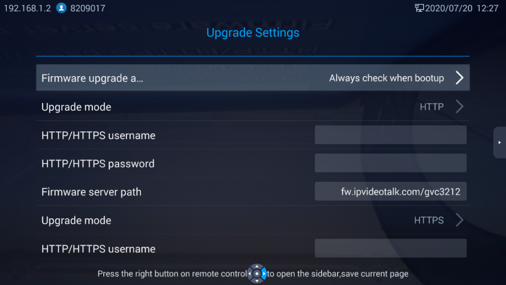
- Firmware and configuration files detection:
Select when to upgrade or initiate provisioning. Users can select “Always Check When Bootup”, “When firmware/config file pre/suffix changes” or “Skip the Firmware Check”.
- Firmware Upgrade Mode:
Select upgrade mode for firmware upgrading. Users could set to TFTP, HTTP or HTTPS. The default setting is HTTPS.
- Firmware HTTP/HTTPS Username
Type the username if the HTTP/HTTPS for the firmware server uses the user authentication mode.
- Firmware HTTP/HTTPS Password
Type the password if the HTTP/HTTPS for the firmware server uses the user authentication mode.
- Firmware Server Path
Configure the server path for the firmware server. The default setting is “fm.ipvideotalk.com/gvc3212”.
- Config Upgrade Mode
Select upgrade mode for config file provisioning. Users could set to TFTP, HTTP or HTTPS. The default setting is HTTPS.
- Config HTTP/HTTPS Username
Type the username if the HTTP/HTTPS for the config server uses the user authentication mode.
- Config HTTP/HTTPS Password
Type the password if the HTTP/HTTPS for the config server uses the user authentication mode.
- Config Server Path
Configure the server path for the config file server. The default setting is “fm.ipvideotalk.com/gvc3212”.
Notes:
- Press Right arrow navigation key to open the sidebar and press on save to save the current settings.
- Press on Back key to cancel the configuration change.
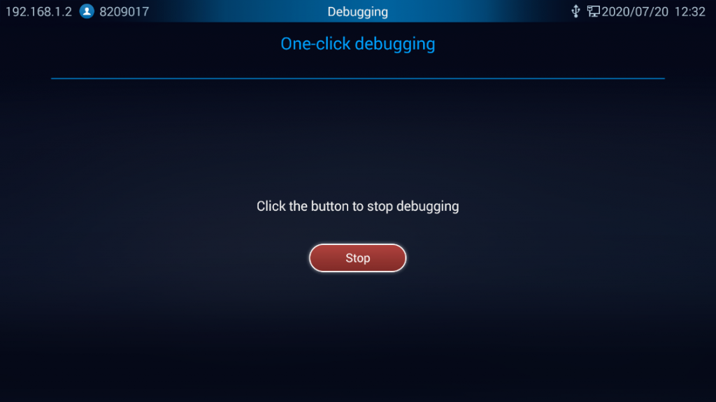
- One click debugging:
Users can start debugging and capturing device logs for troubleshooting purposes on this section, all captured files will be saved on an external USB storage. Pressing on Start button will initiate debugging. Users can stop Debugging by pressing on Stop button, once debugging is stopped, users could then eject the USB device to check the files.
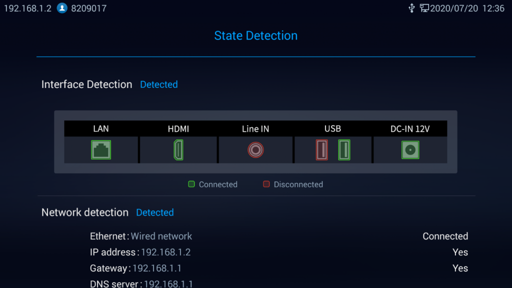
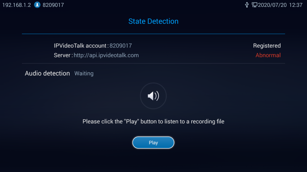
- State Detection:
State detection page provides visual information about the device’s interfaces connection, Network and Accounts status. Users can also perform an Audio detection test to check if the built-in speaker is working:
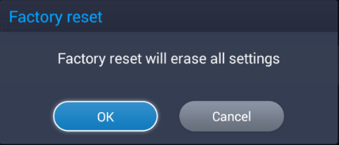
Factory Reset
Users can restore the device to Factory settings by pressing on Restore Factory option. A prompt message will be displayed on screen for users to confirm the factory reset. If the user proceeds with the reset, all configuration and user data will be lost.
IPVIDEOTALK CONFERENCE
GVC3212 supports IPVideoTalk conference and it can be the host to initiate a conference or join other conferences as a member.
Initiating Conference
The conference can be initiated in multiple ways:
- From Call Screen:
- Access the call screen from LCD Menu 🡪 Dial, enter the number in the text box using remote control or select the member from the list below. On the dialing screen, Enter digits in the dial-up box. If the digits or the letters for the digit match contacts and call history in GVC3212, a dropdown list of numbers will be displayed. For example, entering 5 (JKL), 6 (MNO), 4 (GHI) and 6 (MNO) will display “5646” or “john” if contact “john” exists. The matching characters will be highlighted in red.
- Press on the remote control or click on button
 on the screen to dial out.
 on the screen to dial out.
- From Schedule:
For more details, please refer to Schedule New Meetings.
- Instant Meetings
User can join their personal conference room directly from LCD Menu 🡪 Instant Meetings.
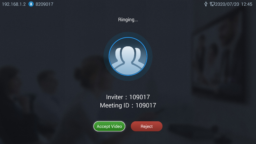
Answering an Incoming Call in Conference
You can specify how your GVC3212 manages incoming calls. Depending on your configuration, your GVC3210 answers a call automatically or prompts you to answer a call manually.
Under LCD Menu 🡪 Advanced Setting 🡪 Account, If Auto Answer option is enabled, Incoming IPVideoTalk calls will be answered automatically. If Auto Answer is disabled, Users can manually accept or decline incoming invitations.
If the conference host answers the call, the caller will join into the current active conference.
Conference Management
On the bottom of the call screen, users will see a list of icons for menu options. This menu will be automatically hidden if there is no operation in 5 seconds. Press any key to bring up the menu options again.
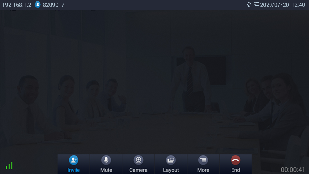
The table below shows the functions for each icon:
Table 8: GVC3210 IPVT Call Screen Bottom Menu Icons
|
Icons |
Name |
Definitions |
 |
Add Member |
Users can add new members to the conference either from the corporate contact phonebook or by dialing their number in the dial screen. |
 |
Mute |
Other call parties will not hear you if you mute yourself. Press the button again to unmute. |
 |
Camera |
Turn On/Off local camera. |
 |
Layout |
Adjust the layout for the video display for video call. Conference host can choose the meeting layout from Meeting Layout, the following layouts are available: Tile: The video for all attendees will be tiled and adapted automatically based on the number of video images. 1+N: One large video image with N smaller video images (polling mode). The current large video image is displaying the video image from current speaker. |
 |
More |
This option allows conference host to start Recording by pressing on Record, the recorded call will be saved in the account’s IPVideoTalk Cloud. Users can bring up DTMF dialing screen by pressing on Open DTMF Option. Users also adjust Echo Delay feature and view Meeting details. |
 |
End |
Conference host can choose to either just exit the meeting by pressing on Leave alone, the conference in this case will continue. Or End the meeting completely by pressing on End the meeting. |
Accessing Personal meeting room
Users can start an instant meeting and access their personal meeting room from LCD Menu 🡪 Instant Meetings.
Missed Call
When there is a missed call, the Dial icon  on home screen will show the number of missed calls. Once accessed the dial screen, the reminder icon will disappear.
Invite Members to Conference
Users could use one of the following ways to add members:
- Access the dial screen by clicking on the ADD icon
 on conference screen. Then, choose to either add member from the corporate phonebook by pressing on Corporate Contact or invite them by dialing out their number by choosing Invite by dial number. Once the member answers the call, it will be connected into the conference automatically.
 - When a member calls the conference number. If the host answers the call, the member will be added into conference automatically.
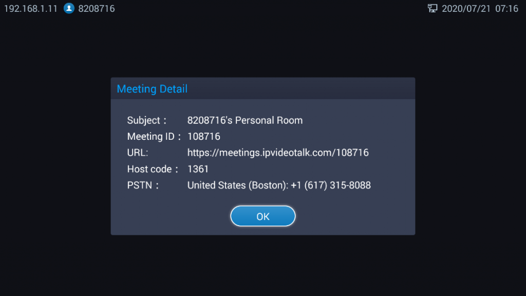
Meeting Details
Users can view the meeting related details such as the subject, Meeting ID, Meeting’s URL, PSTN number by pressing on More button ![]() and selecting meetings details:
and selecting meetings details:
Open DTMF
Users can dial DTMF during a conference.
- During Conference, Press More button option
 , Then choose Open DTMF Option to bring up DTMF dialing
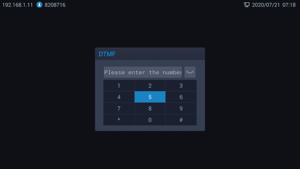
- Press the digital keys on the remote control to input DTMF then on # to send. Press on the remote control to cancel the operation if needed.
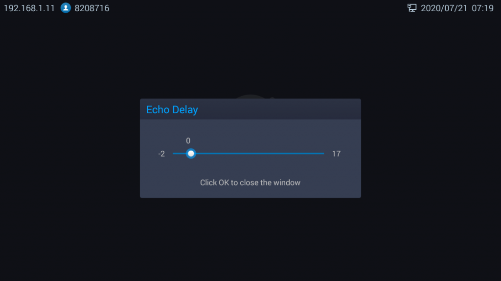
Echo Delay
When GVC3212 connects to a HDMI external display (e.g. TV), echo may generate during in a call. Echo Delay feature configures the device’s HDMI audio delay to match the audio latency of different TV sets. Meeting host can adjust Echo delay feature by pressing on ![]() and select Echo Delay.
and select Echo Delay.
End Conference
To end the conference, tap on END button ![]() or press key on GVC3212 remote control and choose either “Leave alone” or “End the meeting”. If GVC3212 is the conference host:
or press key on GVC3212 remote control and choose either “Leave alone” or “End the meeting”. If GVC3212 is the conference host:
- Select “Leave alone” so that the GVC host will leave the conference while the IPVT conference will still be going on. The GVC Host can still host or end the meeting by selecting it from Conference List Section.
- Select “End the meeting” so that the IPVT conference will be ended and all the other participants will be disconnected from the IPVT server.
- Select “Cancel” to Cancel ending the meeting and resume conference.
If the conference member hangs up the call, it will be disconnected from the conference, but other parties in the conference will stay in the conference.
Schedule New Meetings
Schedule feature allows users to set a specific time to host a conference in advance, with conference reminder and members. Users can schedule new meetings from LCD Menu 🡪 Schedule.
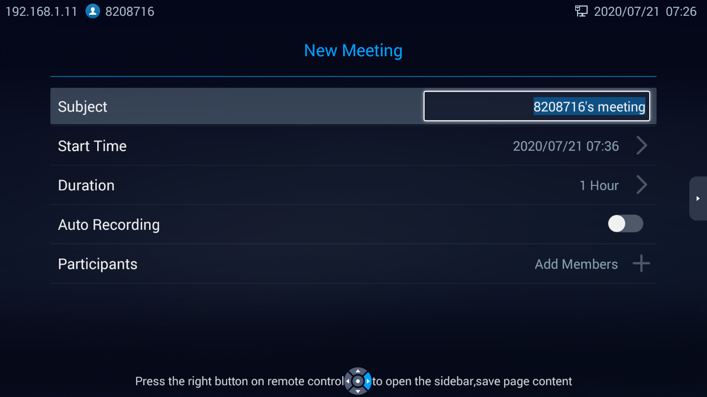
Users could set the meeting details such as the subject of the meeting, starting time and duration, Enable/Disable Auto recording (Recorded meeting saved in the cloud), and set the invitees list by adding them to Participants. User can press on the Add Members next to Participants to add invitees from call history and Local contacts or from the Enterprise phonebook.
By pressing on right arrow navigation key and selecting save, the new meeting schedule will be saved in [Meeting List].
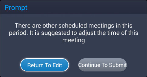
When the new conference start time or duration intersect with an already scheduled conference, a popup message will be displaying onscreen for users to either edit the new meeting details or submit anyway.
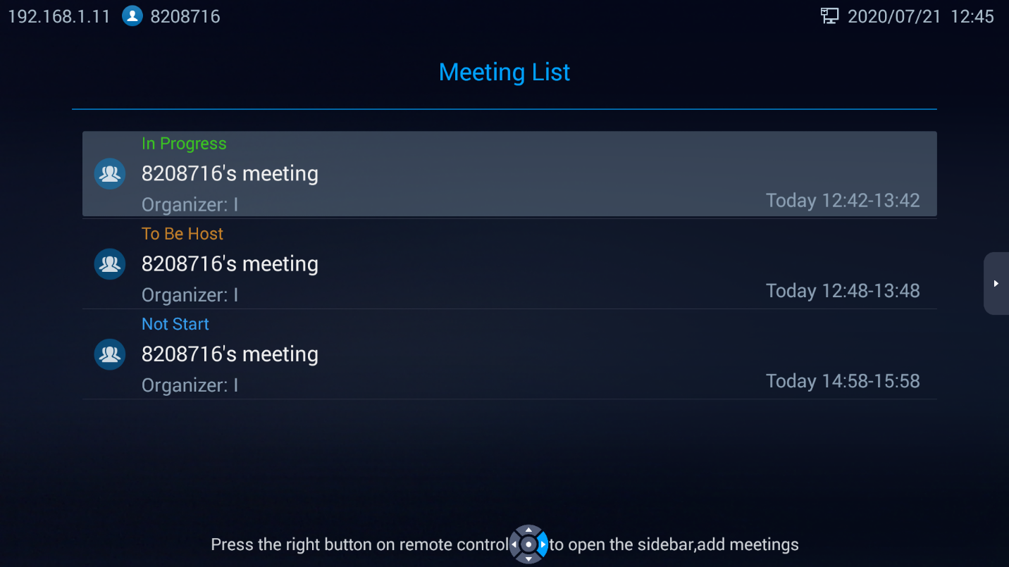
Meeting List
Users could view ongoing conference details along with scheduled conferences after the current time by accessing LCD Menu 🡪 Meeting List. Select one conference and press “OK” key on GVC3212 remote control to view conference details.
Ongoing meetings will be labeled as In Progress. Users can select an in-progress conference and choose to either Host the meeting or End it.
The scheduled meetings that did not start yet are labeled as Not Start. Users can select this meeting on the conference list and choose to Edit the conference, Cancel the conference, or start it.
When a scheduled meeting start time comes and the conference host did not accept the incoming conference call, the meeting will be labeled as to be host in the conference list. The host can then choose to either Start the meeting or Cancel it.
Contacts
Local contacts
From LCD Menu 🡪 Contacts 🡪 Local Contacts Users can choose to access their local contacts directory and add or edit contacts in the local directory.
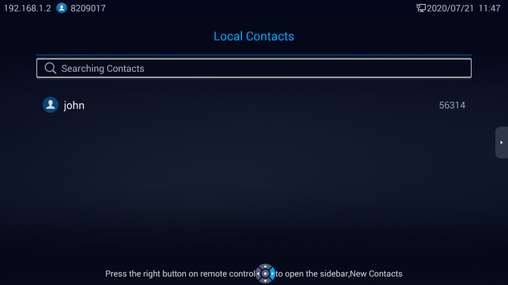
- Operations
- Search: Users could input keyword in the search box. GVC3212 will display contacts automatically which is related to the search keyword. Fuzzy search and precise search are both supported.
- Call: Select the contact and press on GVC3212 remote control or Press on the contact and choose Call number.
- Add: Press Right arrow key on the remote control and then press on New Contact, fill in contact information and on the right arrow key and then choose save.
- Edit: Choose a contact then choose Edit. Press Right arrow key then on save to save the changes.
- Contact Details: Select one contact and press “OK” key on the remote control to view contact details.
Enterprise Phonebook
The contacts are managed centrally in the server side. Users can access it from LCD Menu 🡪 Contacts 🡪 Enterprise phonebook. This will show the Enterprise Contacts screen.
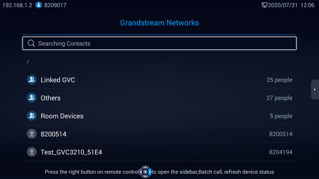
- Select an entry in the directory and press the Green Call button
 on the GVC3212 remote control to call this contact or Select a contact and Press on OK button then on Dial.
 - Press right arrow key on the remote control and then on Refresh to refresh the directory.
- Select the search box and input character or digits to look for contacts.
- Press right arrow key on the remote control then on Batch Call, then select a group of contacts to call multiple contacts simultaneously.
EXPERIENCING GVC3212
Please visit our website: http://www.grandstream.com to receive the most up-to-date updates on firmware releases, additional features, FAQs, documentation and news on new products.
We encourage you to browse our product related documentation, FAQs and User and Developer Forum for answers to your general questions. If you have purchased our products through a Grandstream Certified Partner or Reseller, please contact them directly for immediate support.
Our technical support staff is trained and ready to answer all of your questions. Contact a technical support member or submit a trouble ticket online to receive in-depth support.
Thank you again for purchasing Grandstream Video Conferencing System, it will be sure to bring convenience and color to both your business and personal life.
——————————————————————————————————————————————–
* Android is a trademark of Google LLC.
HDMI, the HDMI Logo, and High-Definition Multimedia Interface are trademarks or
registered trademarks of HDMI Licensing LLC in the United States and other countries.
——————————————————————————————————————————————–
CHANGE LOG
This section documents significant changes from previous versions of GVC3212 user manuals. Only major new features or major document updates are listed here. Minor updates for corrections or editing are not documented here.
Firmware Version 1.0.1.6
- No major changes.
Firmware Version 1.0.0.6
- This is the initial version.