
WELCOME
Thank you for purchasing Grandstream GVC3220 Ultra HD Multimedia Conferencing System. This document introduces the LCD settings, and basic configuration of the GVC3220. To learn Web GUI settings and advanced configuration, please visit http://www.grandstream.com/support to download the latest “GVC3220 Admin Guide”.
The GVC3220 is a revolutionary video conferencing system that provides an interactive and immersive video conferencing environment to increase collaboration and productivity. This SIP-based GVC3220 allows the user to connect their video conferencing solutions with any 3rd-party SIP or H.323 video conferencing platform. Additionally, since the GVC3220 is based on an Android 9.0 operating system. Users will elevate their experience with its 4K Ultra-HD video, up to 5-way 1080P video conferences, screen-sharing capabilities, Integrated Wi-Fi, Bluetooth and more.
The GVC series supports Grandstream’s IPVideoTalk Video and Web Conferencing platform. This paid subscription-based service allows users to turn any meeting hosted on any GVC device into an online meeting that can be joined seamlessly from a web browser or GVC. Turn any physical room into a virtual, online meeting place to offer your customers the tools they need to be successful, no matter where they are.
The GVC3220 eliminates the traditional barriers to video conferencing and sets a new bar for business-class video conferencing solutions by offering industry-leading flexibility, interoperability, system compatibility, application richness and ease of use.
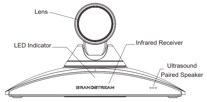
PRODUCT OVERVIEW
INSTALLING GVC3220
Equipment Package Content
GVC3220 package contains the following items:
1x GVC3220 video conference system |
1x GMD1208 wireless microphone |
1x Remote Control |
4x AAA batteries |
1x network cable (2 meters) |
1x lens cleaning cloth |
1x lens cover |
1x Wall Mount Bracket |
1x Universal Power Supply:
|
Screws and Anchors:
|
HDMI cables:
|
Quick Installation Guide |
Table 2: GVC3220 Package List
Connecting GVC3220
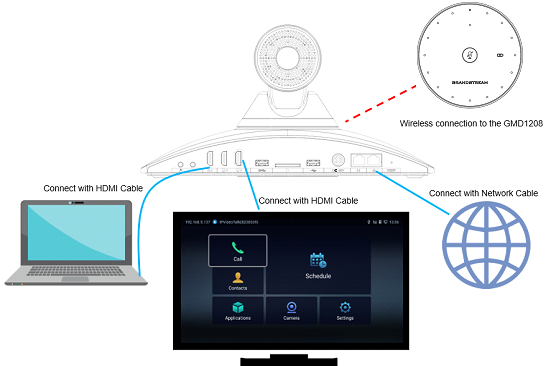
Please connect GVC3220 according to the following procedures:
- Connect the LAN port of the GVC3220 to the RJ-45 socket of a hub/switch or a router (LAN side of the router) using the Ethernet cable.
- Connect the primary HDMI output port (marked with a blue highlight) of the GVC3220 to the HDMI port of the main display device (e.g., TV)
– Using the HDMI cable. Connect the second HDMI output port if you have additional display devices.
Note: There are 2 HDMI output ports. The interface marked with a blue highlight is the primary interface to output primary video. Please make sure to follow the port order when connecting HDMI output ports. When there is only 1 HDMI output, it has to use the primary HDMI port. Connect the secondary HDMI output port only if you have additional display devices. GVC3220 will not work correctly if connecting the secondary HDMI output port without making sure primary HDMI output port is connected. - Connect the 48V DC output plug to the power jack on the GVC3220; plug the power adapter into an electrical outlet.
- The display device (e.g., TV) will show the idle HOME screen with IP address on the top status bar.
- Insert your SD card into the SD card slot. The recording files will be saved in SD card.
- (Optional) Connect presentation device (e.g., a laptop) to the GVC3220 HDMI IN port for presentation purpose during conference call.
- (Optional) Connect USB accessory (e.g., mouse, keyboard, USB flash drive and etc.) to the USB port.
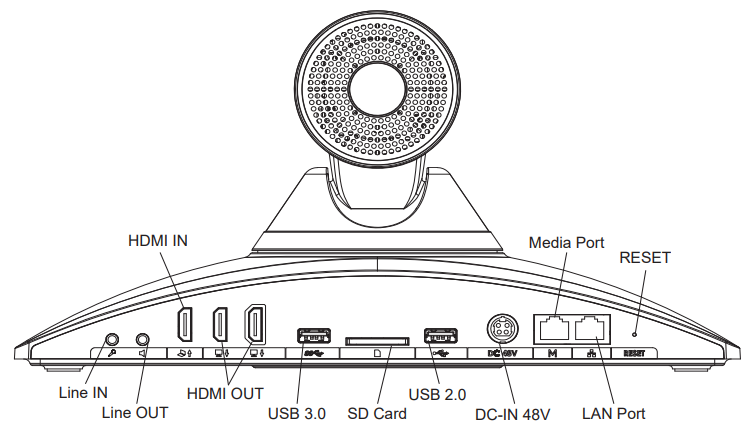
Name | Explanation |
Line IN | Connect an external Microphone |
Line OUT | Connect an external Speaker |
HDMI Input Interface | Connect to an HDMI input device for presentation. |
HDMI Output Interface | Connect the HDMI display devices. Note: There are 2 HDMI output ports. The interface marked with a blue highlight is the primary interface to output primary video. Please make sure to follow the port order when connecting HDMI output ports. When there is only 1 HDMI output, it has to use the primary HDMI port. Connect the secondary HDMI output port only if you have additional display devices. GVC3220 will not work correctly if connecting the secondary HDMI output port without making sure primary HDMI output port is connected. |
SD Card Slot | Insert SD card to store call recordings and other necessary files. |
USB Interface | Connect to USB device (storage, mouse, keyboard …). |
Network Interface | Connect to LAN port. |
Power Interface | Connect to power adapter. The arrow indicator on the power adapter should face upwards when the power adapter is plugged in. |
Factory Restore | When powering up GVC3220, keep pressing the button with a small pin for more than 10 seconds to restore to factory settings. |
Table 3: GVC3220 Back Panel
A sample of GVC3220 back panel connection is shown below:
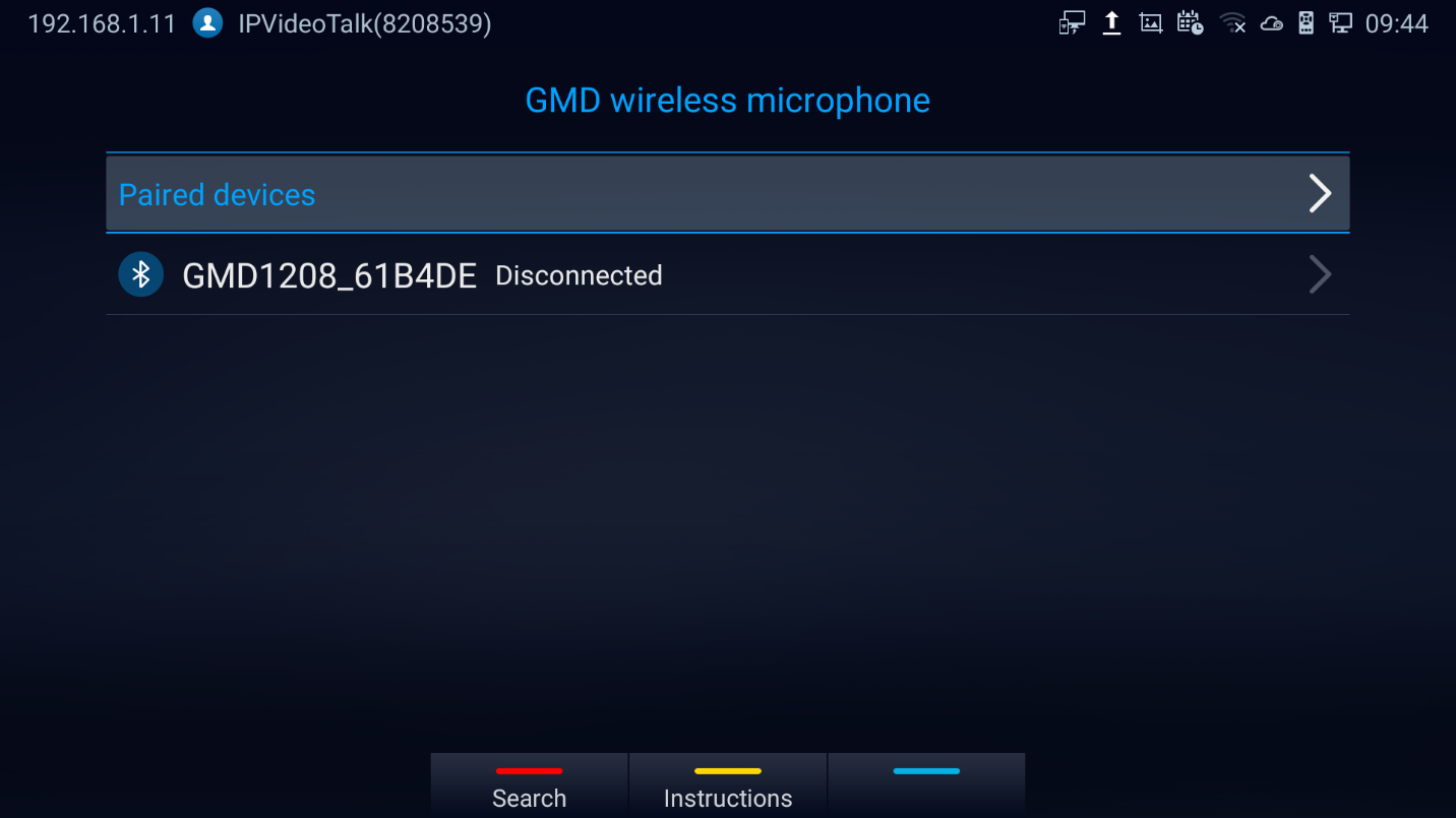
Connecting GMD1208 to GVC3220
- Switch the GMD1208 to 2.4G mode (switch on the back of the device).
- Press and hold the MUTE button of GMD1208 for 3 seconds until the working indicator light is green and the mute light is blinking.
- Bring GMD1208 close to the GVC3220.
- Go to “Settings 🡺 Basic 🡺 GMD Wireless Microphone” page on GVC3220 local GUI and click “Search”. The devices will finish pairing and connection automatically.
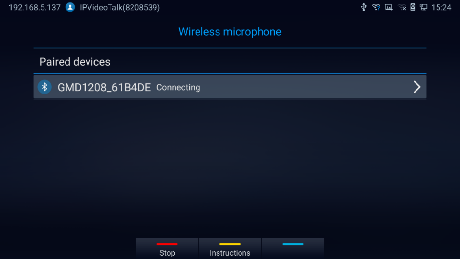
- BT Mode:
- Switch to BT mode. GMD1208 will enter pairing procedure automatically after bootup.
- The Working Status Indicator flashing in blue meaning that GMD1208 is not paired yet.
- When paired, Working Status Indicator will be solid blue.
- USB Mode:
- Switch the GMD1208 to 2.4G mode (switch on the back of the device).
- Then the GMD1208 will automatically pair with GVC3220 when connected via USB.
Note: For more information about GMD1208, please refer to the GMD1208 product page in www.grandstream.com.
For more information about GMD1208, please refer to the GMD1208 product page in www.grandstream.com.
GETTING TO KNOW GVC3220
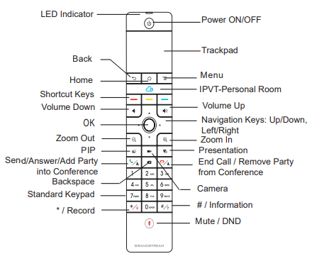
Remote Control
Remote Control Keys and Touchpad
Icon | Name | Explanation |
1, 2, 3, 4…9 | Digital Keys | Input number 1-9 and letters. The letter input using digital keys will not be displayed as letter, but it can be used to search for contacts in Call interface. For example, typing 5 (JKL), 6 (MNO), 4 (GHI), 6 (MNO) can look for John if it exists in GVC3220 contacts list. |
Camera | Switch to PTZ control mode during a call or in idle status. | |
PIP | Switch screen layout in conference. | |
Mute/DND |
| |
Presentation |
| |
Send/Answer/Add Party Into Conference |
| |
End Call/Remove Party From Conference |
| |
Backspace | Press the key to delete input characters. | |
 | Navigation Keys: Up/Down/Left/Right |
|
 | OK |
|
Power On/Off | LCD prompt shows the following three options after pressing this key:
When the power button is pressed second time, the pop-up window will be closed. | |
 | */Record |
|
#/Details |
| |
Shortcut Key: Red | Press each shortcut key for designated functions on different screen context. | |
Shortcut Key: Yellow | ||
Shortcut Key: Blue | ||
Home | Press the key to go back to home screen. | |
Menu | Press the key to view more options. | |
Back | Press the key to go back to the previous screen or exit the current screen. | |
Volume Down | Turn down the device volume. | |
Volume Up | Turn up the device volume. | |
Zoom In | Zoom in screen or adjust close focus. | |
Zoom Out | Zoom out screen or adjust distant focus. | |
Trackpad |
| |
Table 4: GVC3220 Remote Control Keys
Capturing Screenshot Using the Remote Control
To capture a screenshot on GVC3220, the users can press the red shortcut key
![]() and blue shortcut key
and blue shortcut key
![]() at the same time for about 3 seconds. The screenshot picture will be saved in the internal storage of GVC3220. The users can access the screenshot in GVC3220 LCD menu 🡺 Applications 🡺 File Manager 🡺 Internal Storage 🡺 Pictures 🡺 Screenshot.
at the same time for about 3 seconds. The screenshot picture will be saved in the internal storage of GVC3220. The users can access the screenshot in GVC3220 LCD menu 🡺 Applications 🡺 File Manager 🡺 Internal Storage 🡺 Pictures 🡺 Screenshot.
Please note the screenshot folder will include two pictures: The image captured from the camera and the TV/Monitor screenshot.
Using the Remote Control
GVC3220 remote control is connected to GVC3220 via Bluetooth, and it is already pre-paired when the user receives GVC3220 packages. Before using the remote control, please make sure:
- Four AAA batteries are correctly installed on the back of the remote control.
- The remote control needs to be placed within the Bluetooth effective range, i.e., 10m from GVC3220.
After powering up GVC3220, pressing “OK” key on the remote control, it will initiate connection and the remote control can be used right away.
If the remote control fails to pair and connect to GVC3220, please follow the steps below to troubleshoot:
- Check the battery polarity when placed into the battery case. Make sure the batteries are placed in the correct direction in the remote control.
- Check the battery power.
Controlling the camera and Zoom/PTZ functions in GVC3220 are supported with Third Party Applications such as Teams, Zoom and WebEx.
For Teams meeting:
- The navigation keys control the PTZ.
- Double click the trackpad to bring and navigate in the meeting settings.
For Zoom meeting:
- The navigation keys control the PTZ.
- Use the trackpad to bring and navigate in the meeting settings.
- When the left button of the remote control is pressed, it brings the safe driving mode. The video is stopped and the GVC camera moves accordingly.
Using Mouse & Keyboard
When the USB mouse is plugged into GVC3220, users could make the following operations with the mouse.
- Single click the left key of the USB mouse to perform the following operations:
- Access menu
- Check in the checkbox or enable/disable an option.
- Bring up the drop-down list when clicking on a combo box
- Switch input methods in the input box, tap on the corresponding buttons on the soft keyboard to input characters
-
Double left clicks
 on the soft keyboard can switch to “Always use upper case” in English input method.
- Single click the right key of the USB mouse to exit the current displayed menu. It will go back to the previous menu without saving the configurations.
 on the soft keyboard can switch to “Always use upper case” in English input method.
Using the LED Indicator
GVC3220 LED indicator can be used to notify the users with current status of the device. Please refer to the status description below.
LED Indicator Status | Descriptions |
Solid Green | Booting or the device is already booted up |
Flash Green (per 0.5s) | Pressing any button on the remote control |
Flash Red (per 1s) |
|
Flash Red (per 0.2s) |
|
Flash Red (per 2s) | Sleep mode |
Solid Blue |
|
Flash Blue (per 0.5s) | Pairing the remote control |
Blue/Red Alternately | Aging test |
OFF | Power off |
Status Icons
GVC3220 status icons are displayed on the right side of top status bar on GVC3220 LCD display device. The users can view the top status bar notification details in drop-down panel by long pressing the MENU key on the GVC remote control or pressing UP button when the GVC3220 is in home screen.
For some notifications such as Schedule, Voice Mail…, the users can use the GVC remote control trackpad to select it. It will navigate the users to the corresponding app.
The following table lists the main status icons used on GVC3220.
Icon | Descriptions | Icon | Descriptions | Icon | Descriptions |
Missed Call | 
| Ongoing call | 
| Auto answer is enabled | |

| Ethernet is connected | 
| Ethernet is disconnected | 
| Trying to connect to the Ethernet |

| PPPoE is connected | 
| PPPoE connection is failed | 
| PPPoE is disconnected |

| VLAN is successfully configured | 
| VLAN is being configured | 
| Unread voicemail |

| VPN is connected | 
| VPN connection is failed | 
| Wi-Fi-Display is opened |

| Bluetooth is connected | 
| DND mode is enabled | 
| Download or read firmware errors |

| Remote control Low battery | 
| Remote control is connected and paired | 
| Remote control is not connected and paired |

| Micro SD Card is inserted | 
| USB flash drive is inserted | 
| Speaker is being used |

| Volume is turned to silent | 
| Contacts storage is full | 
| SD card storage is full |

| Wi-Fi is connected. | 
| Wi-Fi is disconnected | 
| Unknown Wi-Fi |

| Call forward is set up |    
Wi-Fi signal strength |
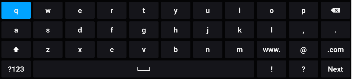
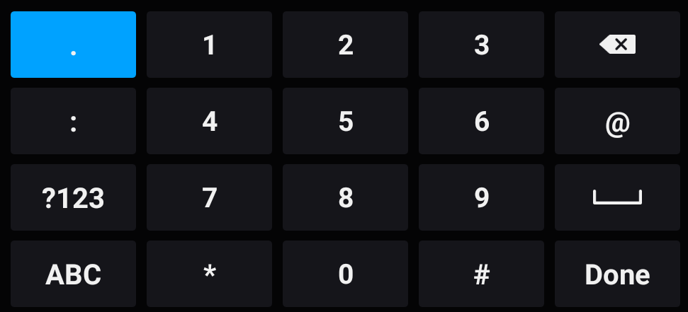
Using the Onscreen Keyboard
English Keyboard
This is the default keyboard on GVC3220. The English keyboard supports multiple languages input methods. See figure below:
 to switch Caps Lock.
 Numbers and Symbols
To input numbers and symbols, tap on button
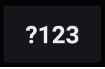 on the default keyboard to switch to numbers/symbols.
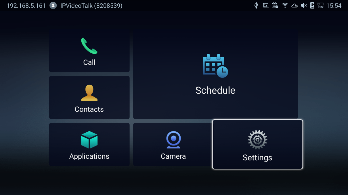
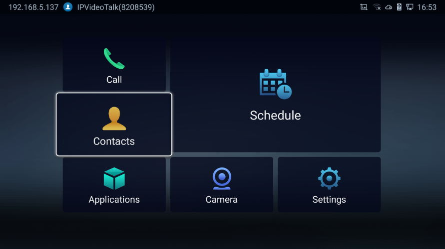
Home Screen
GVC3220 Home screen displays the icons for users to easily access applications, camera, schedule, call, contacts, and settings. Press the navigation keys on the GVC3220 remote control to select an option.
Note: GVC3220 will not automatically hide the main interface. You need to manually press the back key to enter the Camera. Press OK button on the GVC3220 remote control to bring up the icons to display again.
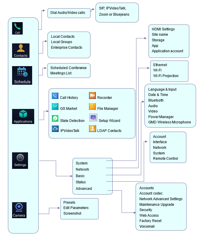
GVC3220 Menu
Every menu opens a list of options. Press Arrow keys to navigate to the menu option you require. Then press “OK” to access further options or confirm the setting displayed. To go to the previous menu item, press “Back”. You can press “Home” key at any time to cancel and return to Home screen.
Screen Lock
The GVC3220 supports screen lock. When it is enabled and configured, the user will be required to enter the lock code to unlock on the home screen. To use this feature, follow the below steps:
- On GVC3220 LCD Menu 🡺 Settings 🡺 Advanced 🡺 Security,
- Select “Screen Lock and password“. Then, set Screen Lock code.
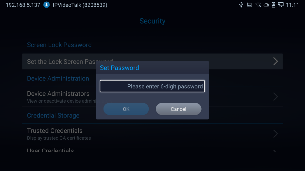
3. Reboot, enter sleep mode or power off the GVC3220.
4. When the GVC3220 boots up again, a screen lock code will be required. The user can unlock the screen by entering the code using the GVC remote control.
System Configurations
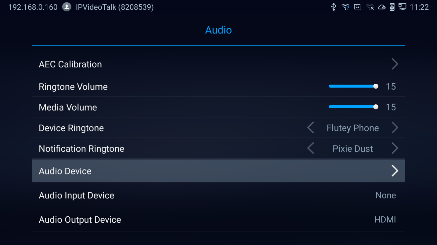
The users can adjust the GVC3220 system configuration under LCD Menu 🡺 Settings 🡺 System.
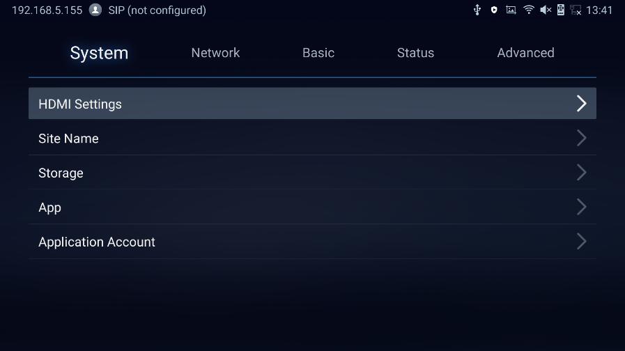
HDMI Settings
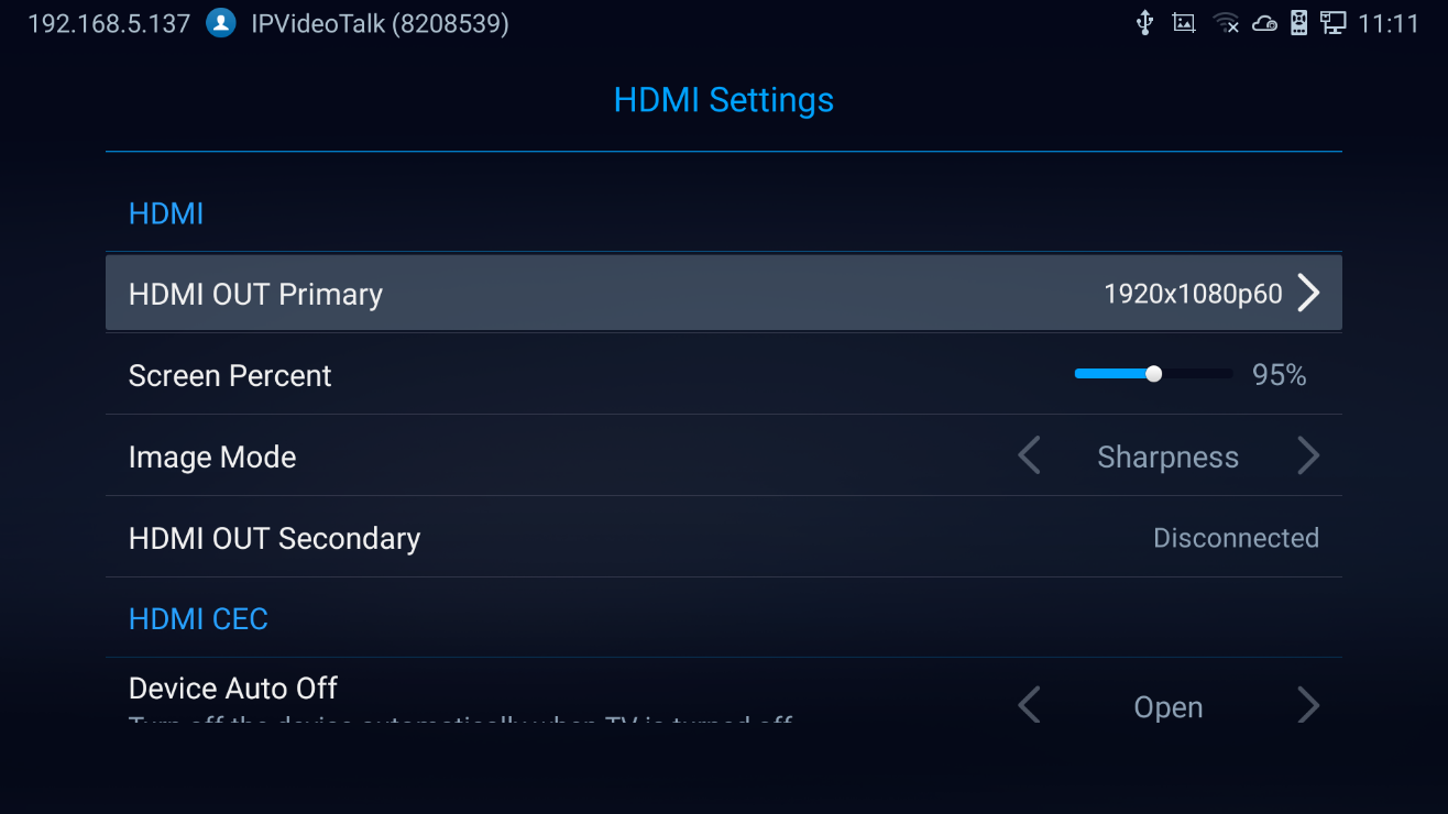
- HDMI 1 Output: Set HDMI 1 out resolution. Up to 1920x1080p60 resolution, default is 1080p (depending on TV resolution).
- HDMI Screen percent: The user can configure screen percent from 90% to 100%. This adjusts the image size displayed on the monitor. Use this option when output device (for example, LCD monitor or TV) is unable to display the GVC3220 screen completely.
- Others: Image Mode, HDMI 2 Output Resolution (This parameter will be set to “Disconnected” if the interface is not used) and HDMI Consumer Electronics Control (Auto turn off the Device/TV).
Site Name
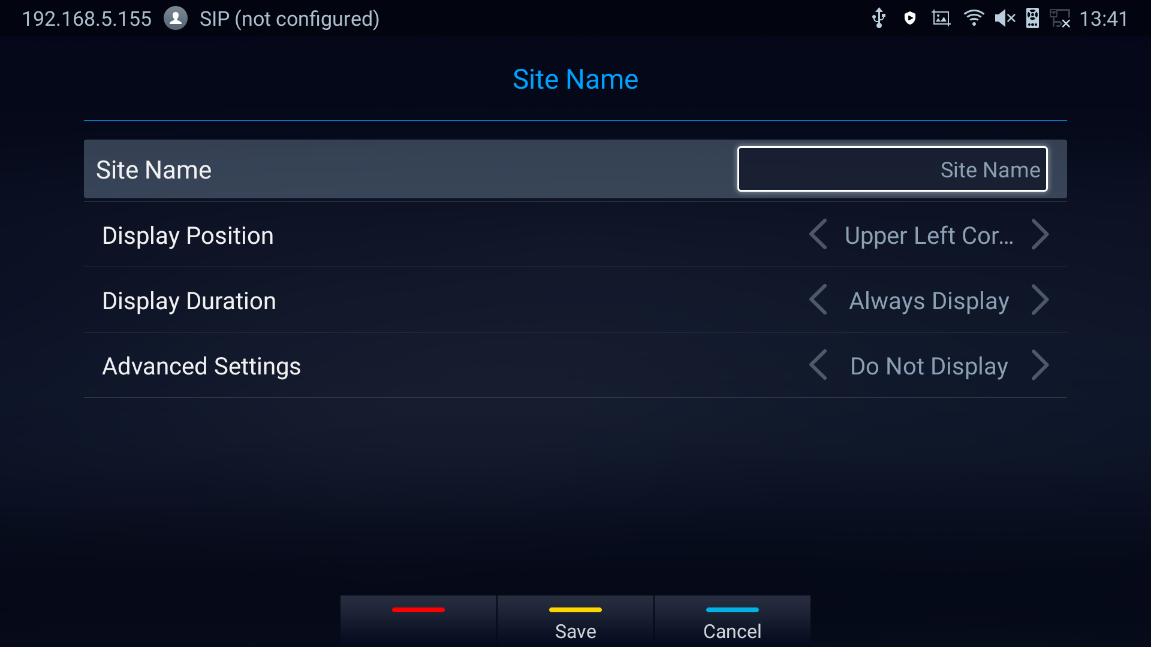
- Site Name: Configure the site name to be imposed on the video of local video.
- Display Position: Configure the site name’s position to be at the Upper Left Corner, Upper Right Corner, Lower Left Corner or Lower Right Corner on the video. The default setting is “Upper Left Corner”.
- Display Duration: Configure the duration to display the site name. The user can select Do No Display, 1 Minute, 5 Minute, 10 Minutes or Always display. The default setting is “Do Not Display”.
- Advanced settings:
- Transparency Set the display background transparency to be Opaque, 5%, 10%,15% and 20%. The default setting is “Opaque”.
- Horizontal Offset Slide left or right to adjust the horizontal position from 0 to 96 for the site to display on the screen. The default setting is 0.
- Vertical Offset Slide up or down to adjust the vertical position from 0 to 96 for the site to display on the screen. The default setting is 0.
- Font Color Select the color in which the site name is displayed. The default color is white.
- Font Size Select the font size from smallest to largest for the site name to display. The default value is Medium.
- Bold Configure whether the site name is displayed in bold. The default setting is “Disabled”.
Storage
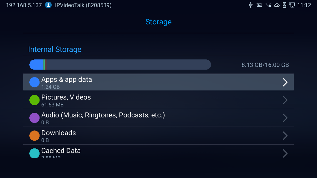
- Display GVC3220 Internal storage details.
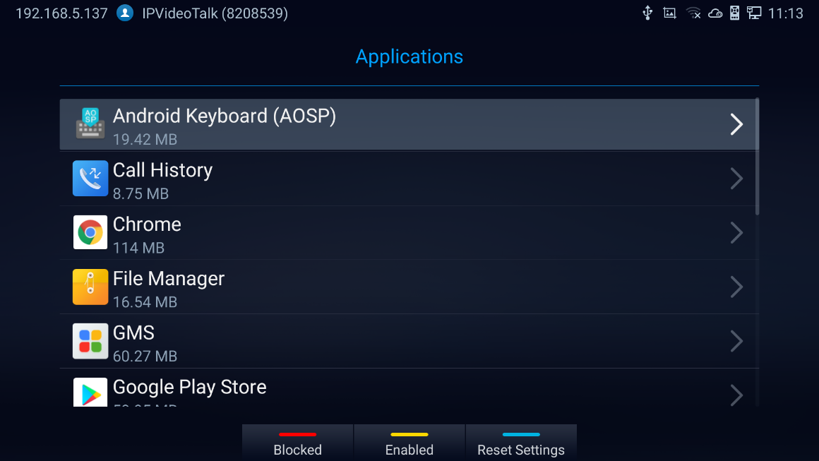
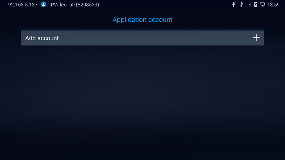
App & Application account
The latter options display available/installed Applications and the related Google Accounts used
CONNECTING TO NETWORK AND DEVICES
GVC3220 supports a variety of network connections (Ethernet, Wi-Fi) and device connections, including USB, SD card and Bluetooth devices. When the GVC3220 boots up for the first time, a setup wizard will guide the users to pair and connect the remote control to GVC3220 and get started with the basic configurations.
Ethernet
If the user would like to use Ethernet connection for network access, please plug the Ethernet cable into the LAN port on the back of GVC3220. Ethernet connection is turned on as DHCP by default on both IPv4 and IPv6 protocols. To configure Ethernet settings on GVC3220, go to LCD menu 🡺 Settings 🡺 Network 🡺 Ethernet.
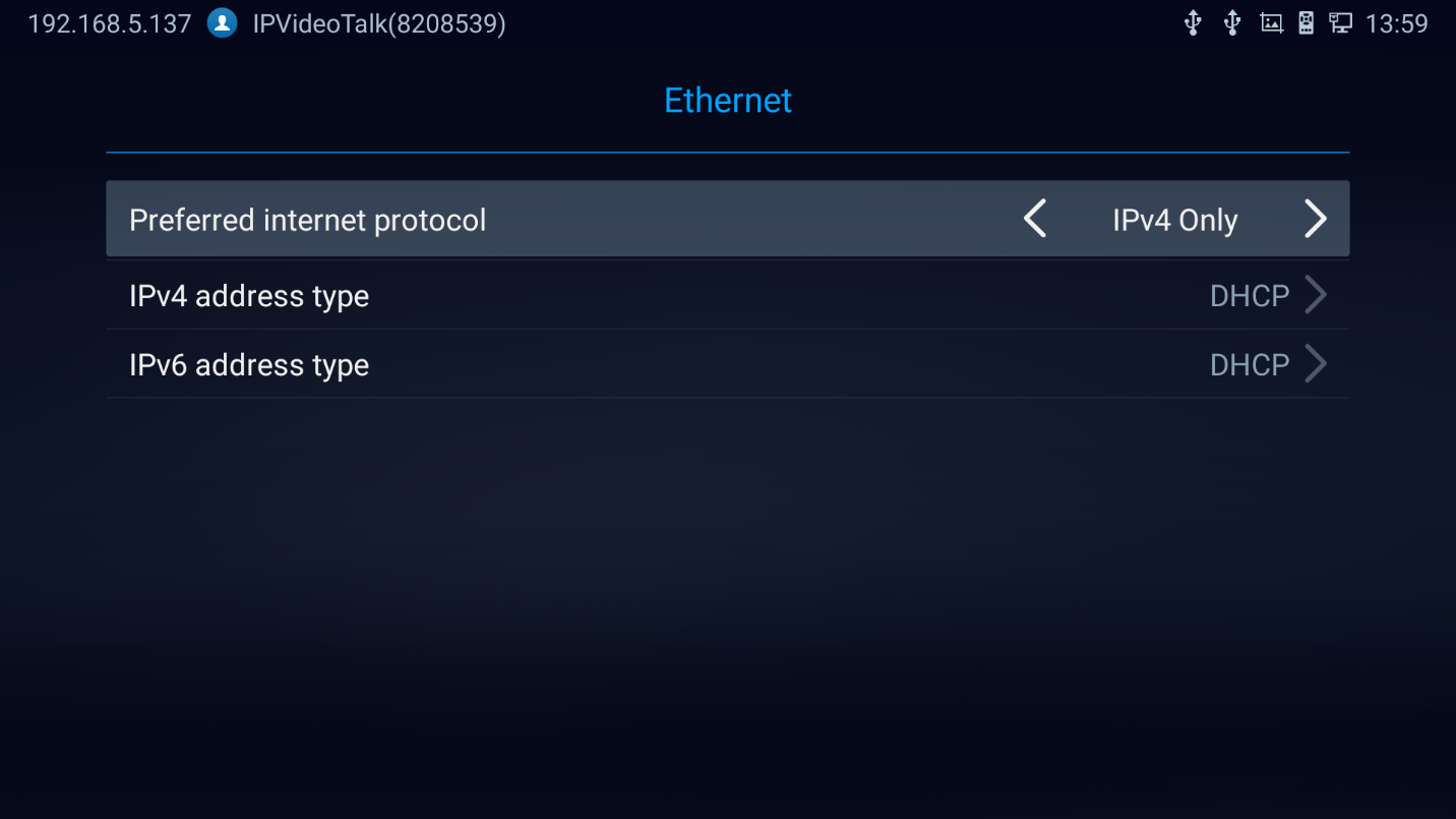
The GVC3220 offers the possibility to prioritize a protocol over another by setting Preferred Internet protocol to IPv4 or IPv6.
Using IPv4
To configure the GVC3220 using IPv4 protocol, follow the below steps:
- Plug the Ethernet cable into the LAN port on the back of GVC3220.
- Go to LCD menu 🡺 Settings 🡺 Network 🡺 Ethernet 🡺 IPv4 Settings.
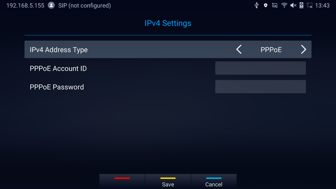
- Tap on “Address Type” to select DHCP, Static IP or PPPoE as the address type.
- For DHCP, save the setting and GVC3220 should be able to get IP address from the DHCP server in the network.

- For static IP, enter IP Address, Subnet Mask, Default Gateway, DNS Server, and Alternative DNS server for GVC3220 to correctly connect to the network.
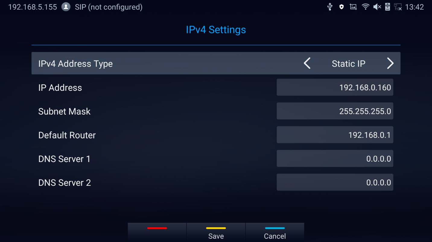
- For PPPoE, enter PPPoE account ID and password so that GVC3220 can get IP address from the PPPoE server.
Notes:
-
Press
 to Save configuration
-
Press
 to Cancel configuration
 to Save configuration
 to Cancel configuration
Using IPv6
To configure the GVC3220 using IPv6 protocol, follow the below steps:
1. Plug the Ethernet cable into the LAN port on the back of the GVC3220
2. Go to LCD menu 🡺 Settings 🡺 Network 🡺 Ethernet 🡺 IPv6 Settings.
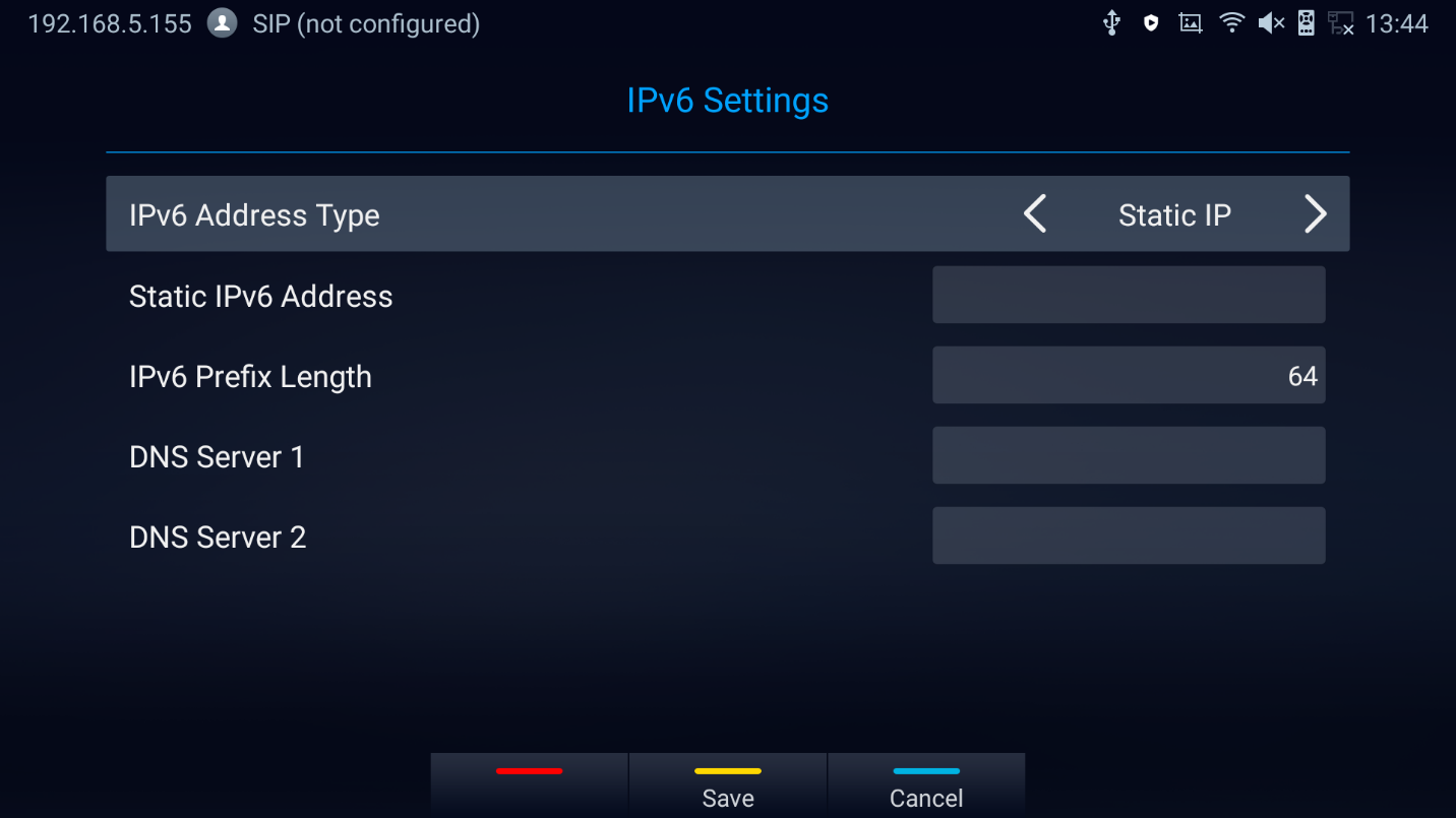
3. Tap “Address Type” to select DHCP or Static IP as the address type.
- For DHCP, save the setting and GVC3220 should be able to get IP address from the DHCP server in the network.
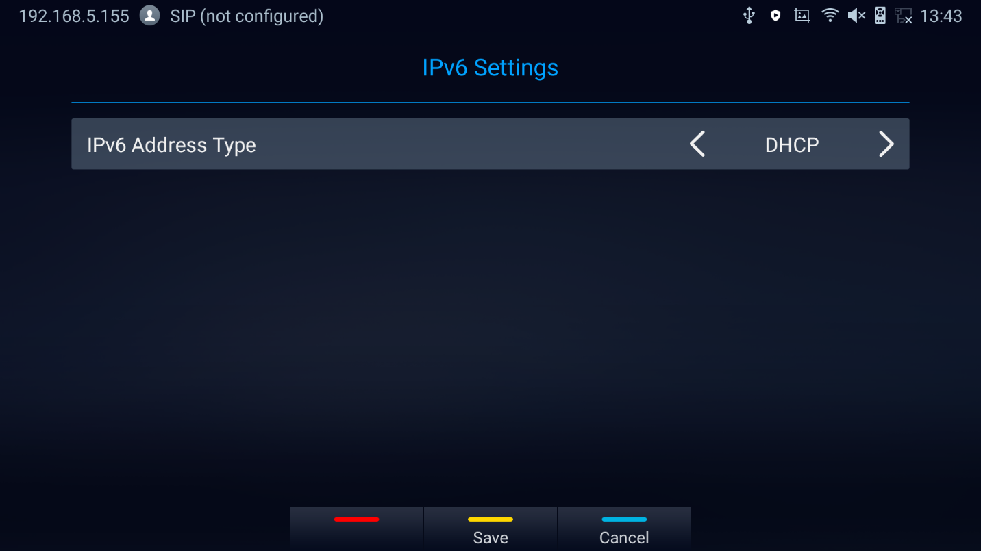
- For static IP, configure IPv6 address, DNS server 1, DNS server 2 and Preferred DNS server, enter the IPv6 address in the format of 2001:db8:1:2::3.
WI-FI
Wi-Fi is supported and built-in on GVC3220 only. On the LCD display, go to Settings 🡺 Network 🡺 Wi-Fi to turn on and configure Wi-Fi.

Turning Wi-Fi On/Off
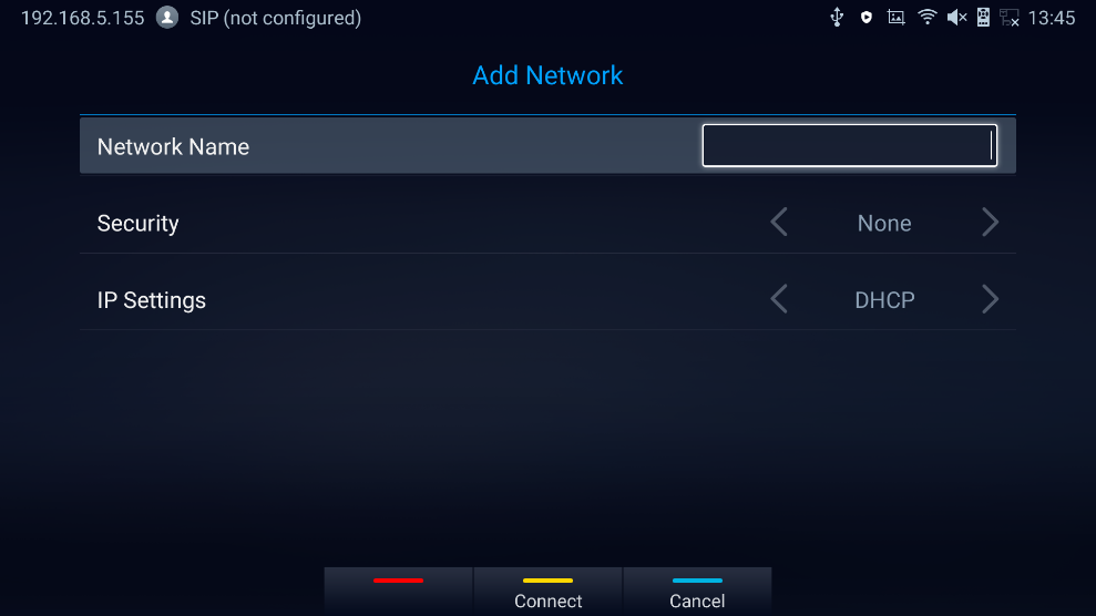
Once Wi-Fi is turned on, GVC3220 will automatically start the scanning within the range. A list of Wi-Fi networks will be displayed as scanning result. Tap on the SSID and enter the correct password information to connect to the selected Wi-Fi network.
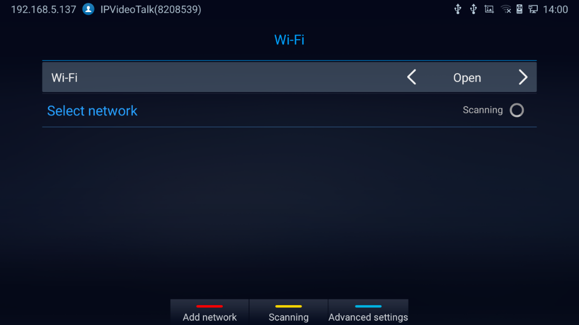
-
Press
 to Scan for available Wi-Fi Networks
-
Press
 to Access advanced Wi-Fi Options. The dialog will show additional option “IP settings”. Select Static IP, enter IP Address, Subnet Mask, and Default Gateway for GVC3220 to correctly connect to the network.
 to Scan for available Wi-Fi Networks
 to Access advanced Wi-Fi Options. The dialog will show additional option “IP settings”. Select Static IP, enter IP Address, Subnet Mask, and Default Gateway for GVC3220 to correctly connect to the network.
Wireless Projection
Wi-Fi Projection feature is used for screen stream mirroring of other devices in the GVC3220 via Wi-Fi. Please refer to the following steps to display your device’s screen on the GVC3220 screen:
-
On the LCD display, go to Settings 🡺 Network 🡺 Wireless Projection
– Set “Open” to enable Wireless Projection Option.
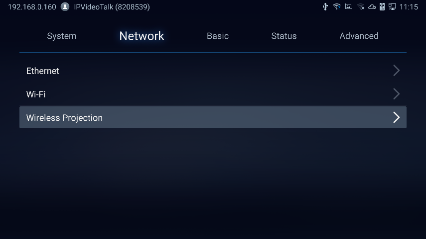
2. On the device you want to cast its screen, go to “Screen mirroring” feature page and enable Wireless projection.
3. The phone will show the GVC3220 in the available devices list.
4. Select the GVC3220. The screen mirroring will start immediately.
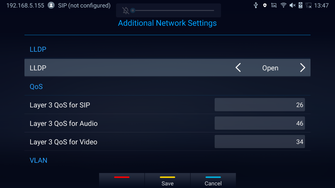
LLDP and VLAN Settings
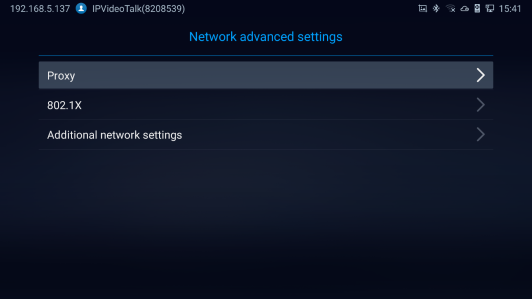
Access GVC3220 home screen, go to Settings 🡺 Advanced 🡺 Network Advanced Settings 🡺 Additional Network Settings to configure LLDP settings on GVC3220.
 to Save configuration
 to Cancel configuration
Parameters | Descriptions |
LLDP | |
LLDP | Enable or disable LLDP. The default setting is “Open”. |
Layer 3 QoS for SIP | This field defines the layer 3 QoS parameter for SIP packets. It is the value used for IP Precedence, Diff-Serv or MPLS. The default value is 26. |
Layer 3 QoS for Audio | This field defines the layer 3 QoS parameter for audio packets. It is the value used for IP Precedence, Diff-Serv or MPLS. The default value is 46. |
Layer 3 QoS for Video | This field defines the layer 3 QoS parameter for video packets. It is the value used for IP Precedence, Diff-Serv or MPLS. The default value is 34. |
Layer 2 QoS 802.1q/VLAN Tag | Assigns the VLAN Tag of the Layer 2 QoS packets for LAN port. The default value is 0. Note: Please do not change the setting before understanding the VLAN’s settings or consulting with the network administrator. Otherwise, the device might not be able to get the correct IP address. |
Layer 2 QoS 802.1p Priority | Assigns the priority value of the Layer 2 QoS packets. The default value is 0. |
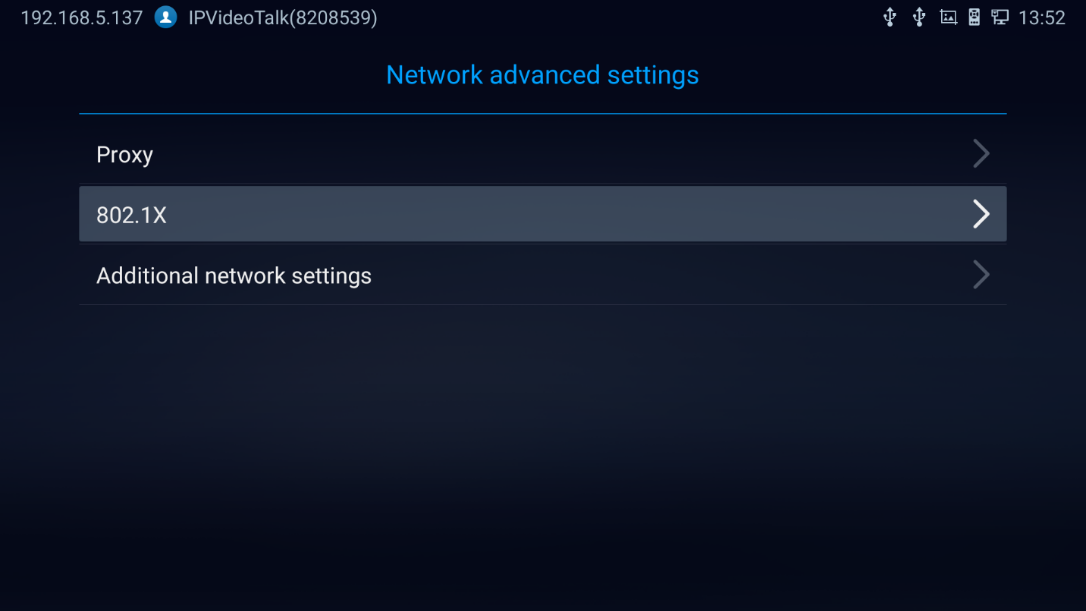
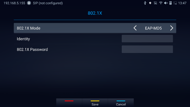
802.1X Mode
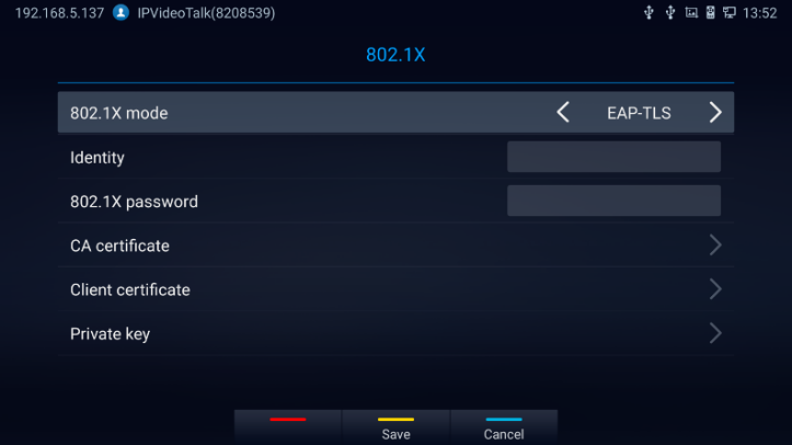
Under Settings 🡺 Advanced 🡺 Network Advanced Settings 🡺 802.1x. By default, 802.1x is disabled. Selecting 802.1x mode to “EAP-MD5”, “EAP-TLS5” or “EAP-PEAP” to turn on 802.1x. Once it is enabled, the user will be required to enter the identity and password to be authenticated in the network.
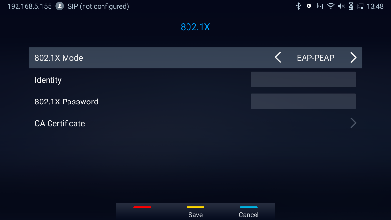
Parameters | Descriptions |
802.1x Mode | Allows the user to enable/disable 802.1x and configure 802.1x mode. The default setting is disabled. |
Identity | Enter the Identity information for 802.1x mode. |
MD5 Password | Enter the MD5 Password for 802.1x mode. |
CA Certificate | Upload the CA certificate for 802.1x mode. |
Client Certificate | Upload the CA certificate for 802.1x mode. |
Private Key | Upload the private key for 802.1x mode. |
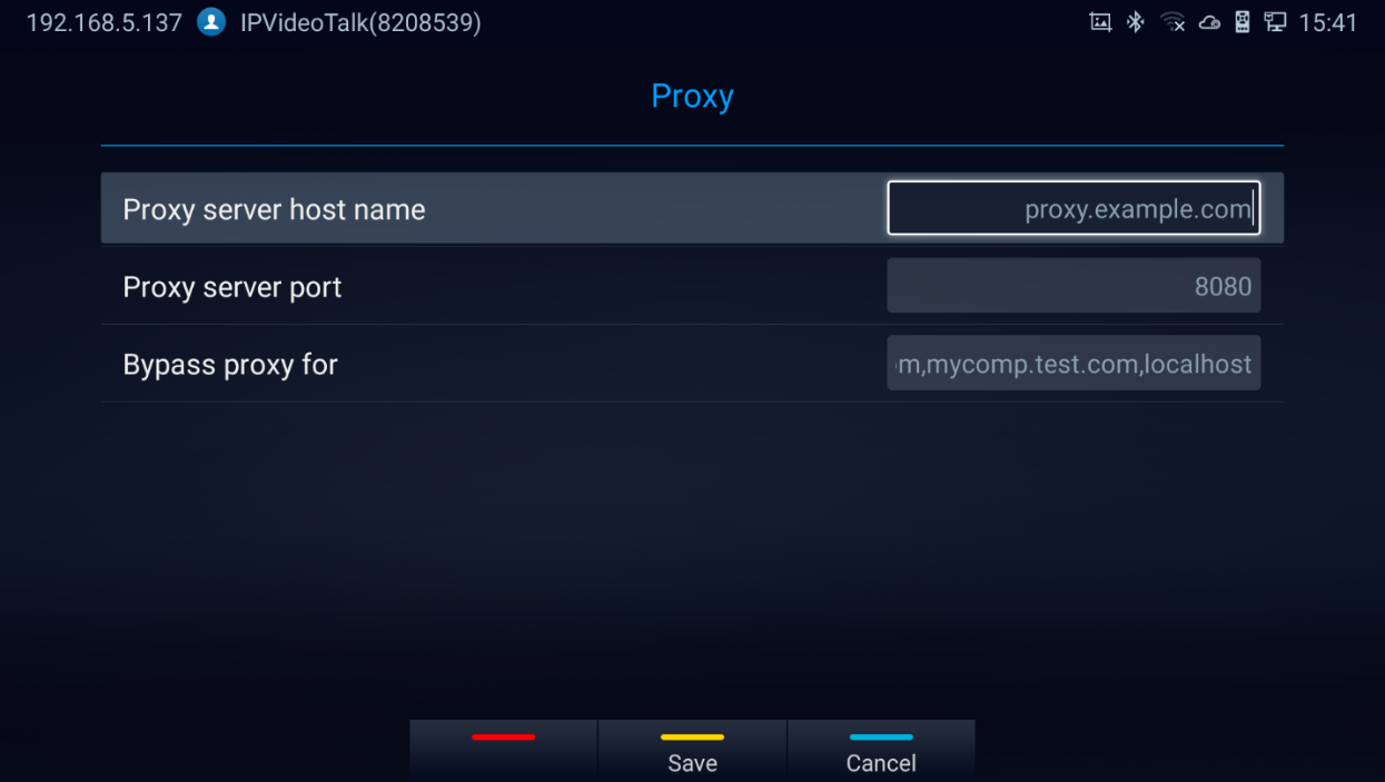
Proxy
If your network requires going through a proxy, you can configure the proxy server, port, and bypass options under Settings 🡺 Advanced 🡺 Network Advanced Settings 🡺 Proxy.
CAMERA
Users could set preset, configure camera parameters, start recording and make screenshots on camera screen. There are 3 ways to access camera screen:
-
Click on
 icon on home screen.
- Press key on the remote control.
 icon on home screen.
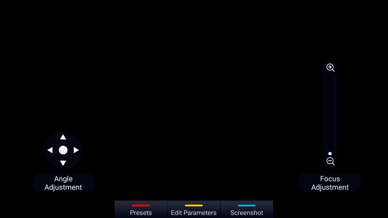
GVC3220 camera screen has the following options:
- Press recording button on the remote control to start or stop local recording.
- Press the red shortcut button on the remote control to edit preset.
- Press the yellow shortcut button on the remote control to edit image parameters such as scene, white balance, MF/AF and etc.
- Press the blue shortcut button on the remote control for screenshot.
- Press digit key on the remote control to apply a pre-configured preset.
Preset
Add Preset
Users can create and save maximum of 24 camera presets, with each preset storing the camera position and focal length. Follow the steps below to add preset:
-
Access camera screen and press
 on the remote control to access preset screen.
 on the remote control to access preset screen.
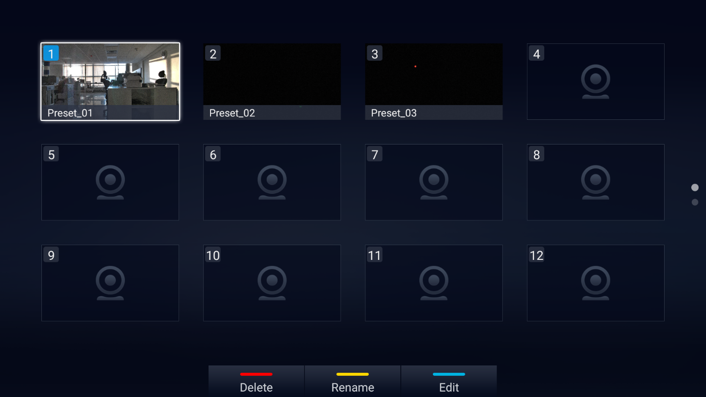
2. Select the preset window and press the blue shortcut key on the remote control to access the editing screen.
3. Adjust camera position and zoom in/zoom out using the remote control.
4. On GVC3220 remote control, press “OK” key to save the preset, or press Back key to cancel.
 to Delete Preset
 to Rename Preset
 to Edit Preset
Camera Parameters Configurations
Press
 shortcut key on GVC3220 remote control to bring out camera parameters setting screen as shown below. Refer to the table below and configure the parameters using navigation keys on the remote control.
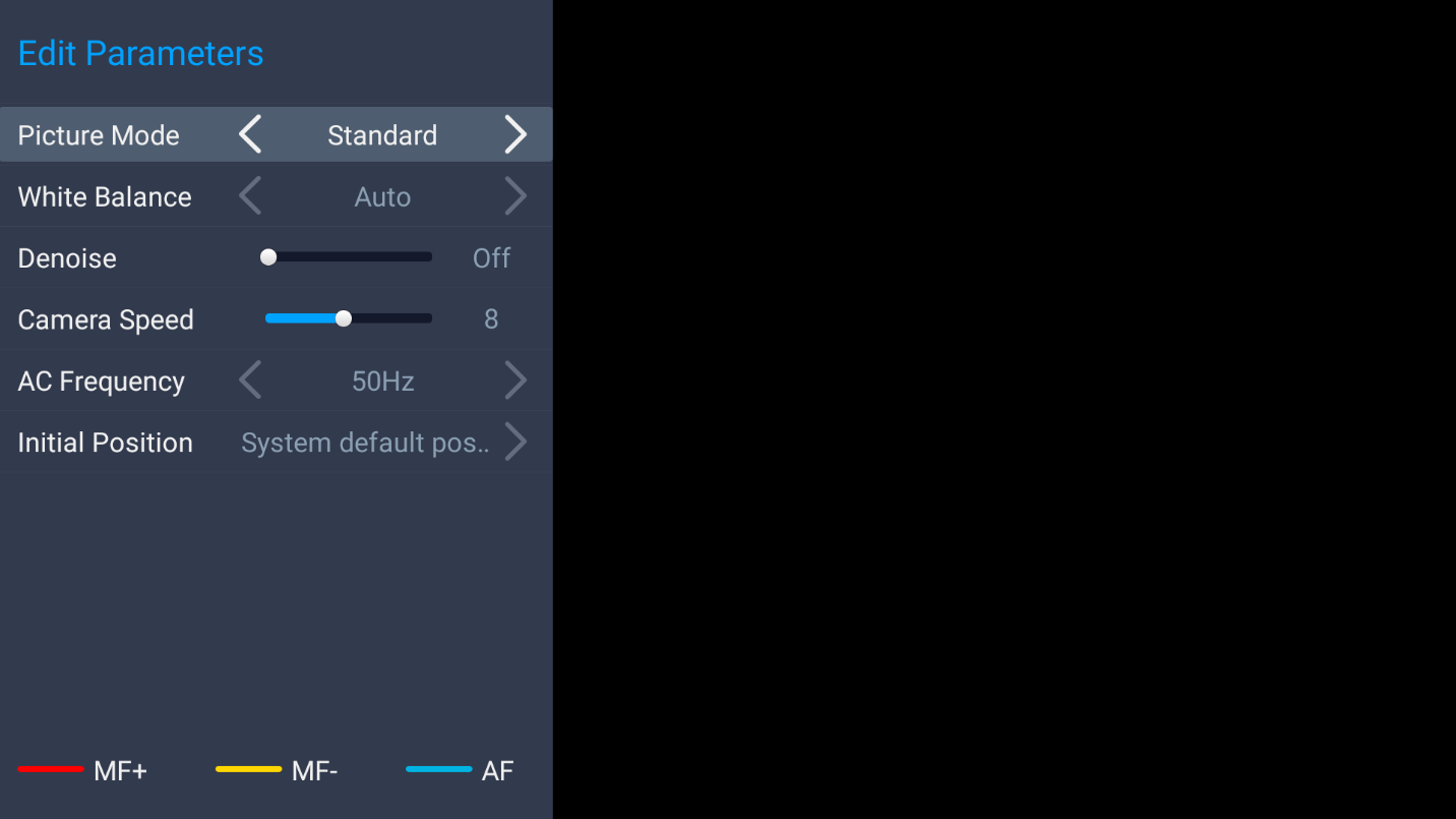
Parameters | Descriptions |
Picture Mode | GVC3220 has 5 built-in modes as well as “Manual” for customization. When set to “Manual”, press “OK” key to access each setting to configure sharpness, contrast, saturation, and brightness.
|
White Balance | This is used to display accurate images. Users could set to “Manual” or “Auto”.
|
De-noise | Users could set to “off”, “low”, “medium” or “high”. Higher reduction level brings less image noises. |
Camera Speed | This option allows configuring the moving speed and zoom speed for the camera. “1” is the slowest and “16” is the fastest. The default is “8”. |
Frequency of A.C. | Users could set to 50HZ or 60HZ. |
Initial Position |
|
Red Shortcut Key (MF+) | Manual focus: increase the focal length. |
Yellow Shortcut Key (MF-) | Manual focus: decrease the focal length. |
Blue Shortcut Key (AF) | Auto focus |
PERIPHERAL
External USB Device
GVC3220 USB interface could be connected with a USB mouse, a USB keyboard, or a USB storage device.
Using USB Mouse/Keyboard
When a USB mouse is plugged into GVC3220, users could see the cursor on the screen, move the cursor to perform operations. When a USB keyboard is plugged into GVC3220, users could use GVC3220 remote control to navigate to an input interface and click on the keys on the keyboard to check if it is installed successfully.
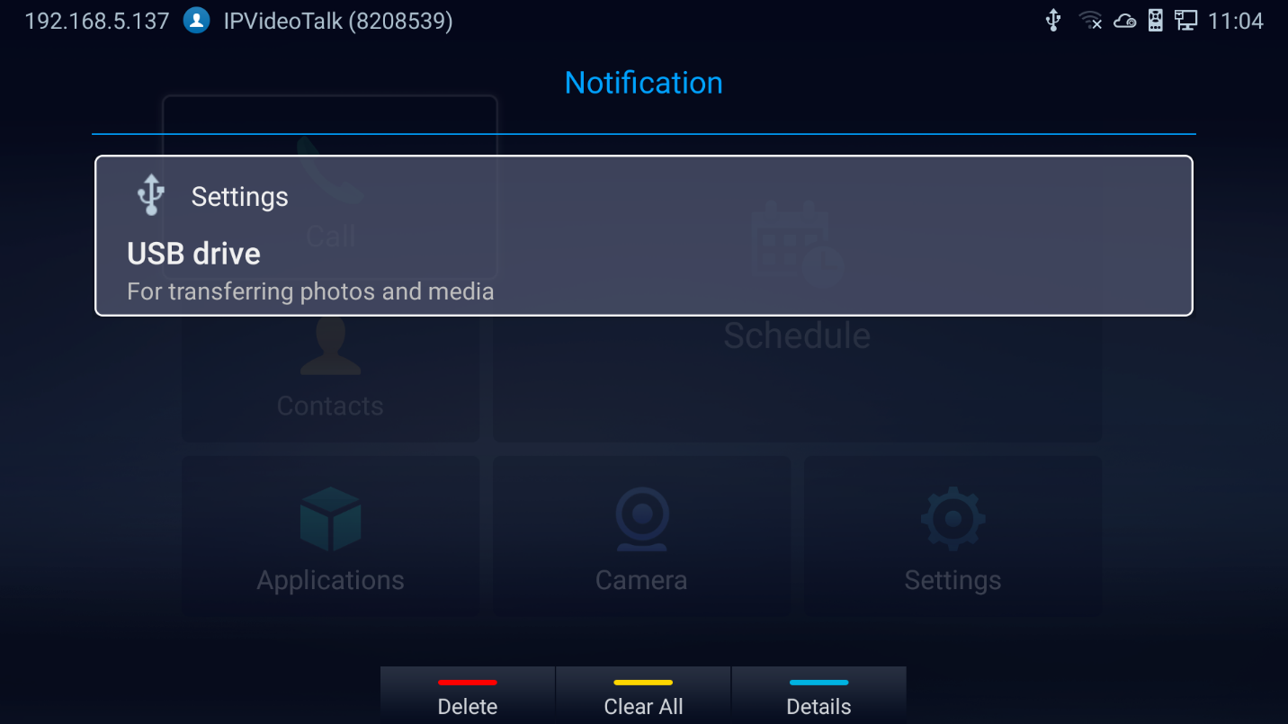
Storage Device
To connect and access USB storage device:
- Insert the storage device into the proper port at the back of GVC3220 (USB or SD Card).
- It will take a few seconds for GVC3220 to prepare the connection.
- Once it is installed successfully, the USB/SD Card icon will show up on the status bar. Users could go to GVC3220 LCD 🡺 Applications 🡺 File Manager 🡺 USB/SD Card to access and manage your data.

4. Users could view, copy/paste or delete files on the USB storage device.
Microphone and Speaker
Users can connect external audio devices as audio input/output sources. It is recommended to use the external speaker GMD1208 that comes with your GVC3220 package for better compatibility. For more information, please refer to the [Connecting GMD1208 to GVC3220] section in this document.
If the external speaker supports Bluetooth, users could also pair and connect the speaker to the GVC3220 via Bluetooth. This will provide better mobility and make cabling easier when deploying the GVC3220 conference system in your conference room.
MAKING PHONE CALLS
Account
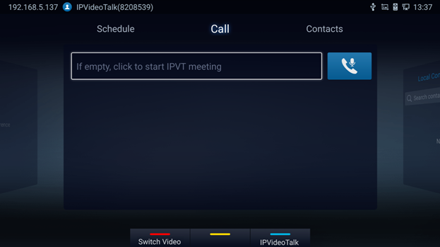
GVC3220 comes with one IPVideoTalk account, supports one configurable SIP account registration, one H.323 account, one Blue Jeans account and one Zoom account. Please enable the IPVideoTalk account or register SIP account to a SIP server before making calls. The following figure shows the IPVideoTalk account is registered successfully. This displays on the left side of the top status bar on your LCD display device.

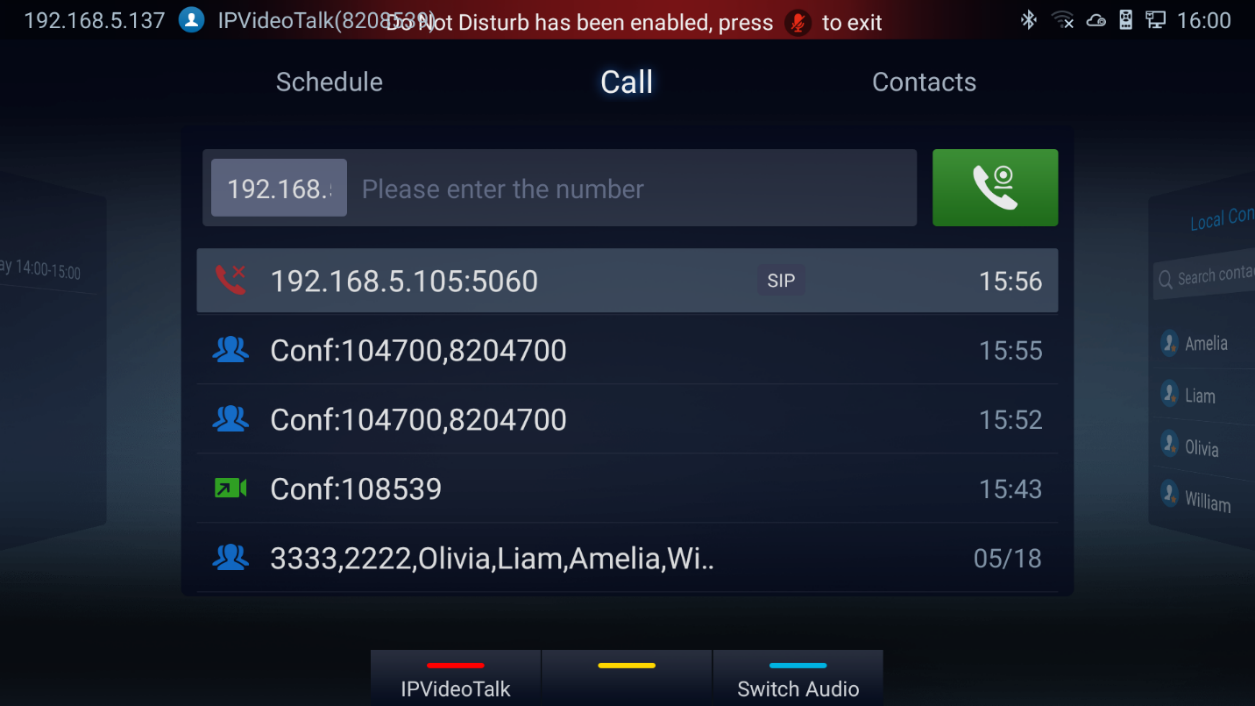
Dial Screen
Once the account is registered successfully, users could use one of the following 2 ways to bring up dial screen to start making calls.
- Press the SEND button from the remote control.
-
On the LCD display device, click on icon
 on home screen.
 on home screen.
Enter digits in the dial-up box. If the digits or the letters for the digit match contacts and call history in GVC3220, a dropdown list of numbers will be displayed. For example, entering 5 (JKL), 6 (MNO), 4 (GHI) and 6 (MNO) will display “5646” or “john” if contact “john” exists. The matching characters will be highlighted in red.
- Press the BLUE shortcut key on the GVC3220 remote control to switch accounts
- Press the RED shortcut key to switch between Audio/Video Call
- Press END CALL button on the remote control to cancel the call.
Dialing a Number Directly
- On the dial screen. Use the remote control keyboard to enter digits or click the input box to enter digits using the pop out soft keyboard.
- Press on the remote control OR move the cursor to the icon
 (Audio Call) /
  (Video call) on the dial screen to dial out.
 (Audio Call) /
  (Video call) on the dial screen to dial out.
 Dialing BlueJeans/Zoom call
GVC3220 has built-in access for users to dial BlueJeans/Zoom calls. Follow the steps below:
- On the LCD dial screen, press the BLUE shortcut key on GVC3220 remote control to switch call mode from SIP Call to BlueJeans or Zoom Call.
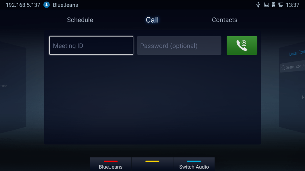
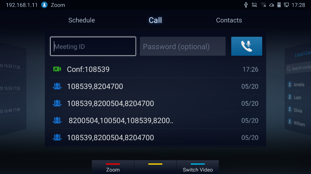
- When the call mode shows BlueJeans or Zoom, input BlueJeans/Zoom conference ID and conference password.
-
Press on the remote control or click on the screen buttons
 \
\
 to dial out a video\Audio call.
 \
\
 to dial out a video\Audio call.
-
Click on
 for to switch between call modes (video or audio)
For more information about how to use BlueJeans on GVC3220, please refer to the link below:
http://www.grandstream.com/sites/default/files/Resources/GVC3220_BlueJeans_application_note.pdf
Redial
Users can dial out the last dialed number if there is dialed call log. Access the dial screen, and then press “#” key or on the remote control to dial out.
Dialing a Number via Contact
Follow the steps below to dial a number via Contacts:
-
On the LCD display device, access Contacts by tapping on button
 on home screen.
- Navigate and select in the contacts entries using the remote control navigation keys.
- Press on the remote control to dial out.
 on home screen.
Dialing a Number via Call History
-
On the LCD display device, access Applications on home screen and access call history by selecting the icon
 .
.
- The LCD will display all call history types. Navigate in the call history list by selecting the call history category. Select the call history entry you would like to dial out.
- Press on the remote control to dial out.
 .
.
Direct IP Call
Direct IP Call allows GVC3220 and another VoIP device to talk to each other in an ad-hoc fashion without a SIP proxy. Direct IP calls can be made if:
- Both GVC3220 and VoIP phone have public IP addresses, Or
- Both GVC3220 and VoIP phone are under the same LAN / VPN using private or public IP addresses, Or
- NAT is disabled or GVC3220 NAT is disabled.
Both devices can be connected through a router using public or private IP addresses (with necessary port forwarding or DMZ).
To make a direct IP call, please follow the steps below:
- Access the dial screen on GVC3220 LCD.
-
Press
 the RED shortcut key on the remote control to bring up call mode setting screen, set the mode to “SIP”.
- Input the target IP address. For example, if the target IP address is 192.168.124.123 and the port is 5062, input the following:
192*168*124*123#5062
The * key represents the dot (.) and the # key represents the colon (:).
-
Press
 the BLUE shortcut key on the remote control to select “Audio Call” or “Video Call”.
- Press on the remote control to dial out.
Paging/Intercom
Before placing paging/intercom, please make sure the callee has paging/intercom enabled so that it can answer the paging/intercom call automatically. To make paging/intercom call:
- Access the dial screen on GVC3220.
- Enter the number to dial followed by *74. Please refer to [Call Features] for more details.
-
Press
the BLUE shortcut key on the remote control to select “Audio Call” or “Video Call”.
- Press on the remote control to dial out.
Contacts
GVC3220 Contacts app helps users to easily store and manage phone numbers and contacts information. Users can add contacts on GVC3220 or import contacts from external devices as well as download from a server. On GVC3220 home screen, click on “Contacts”.
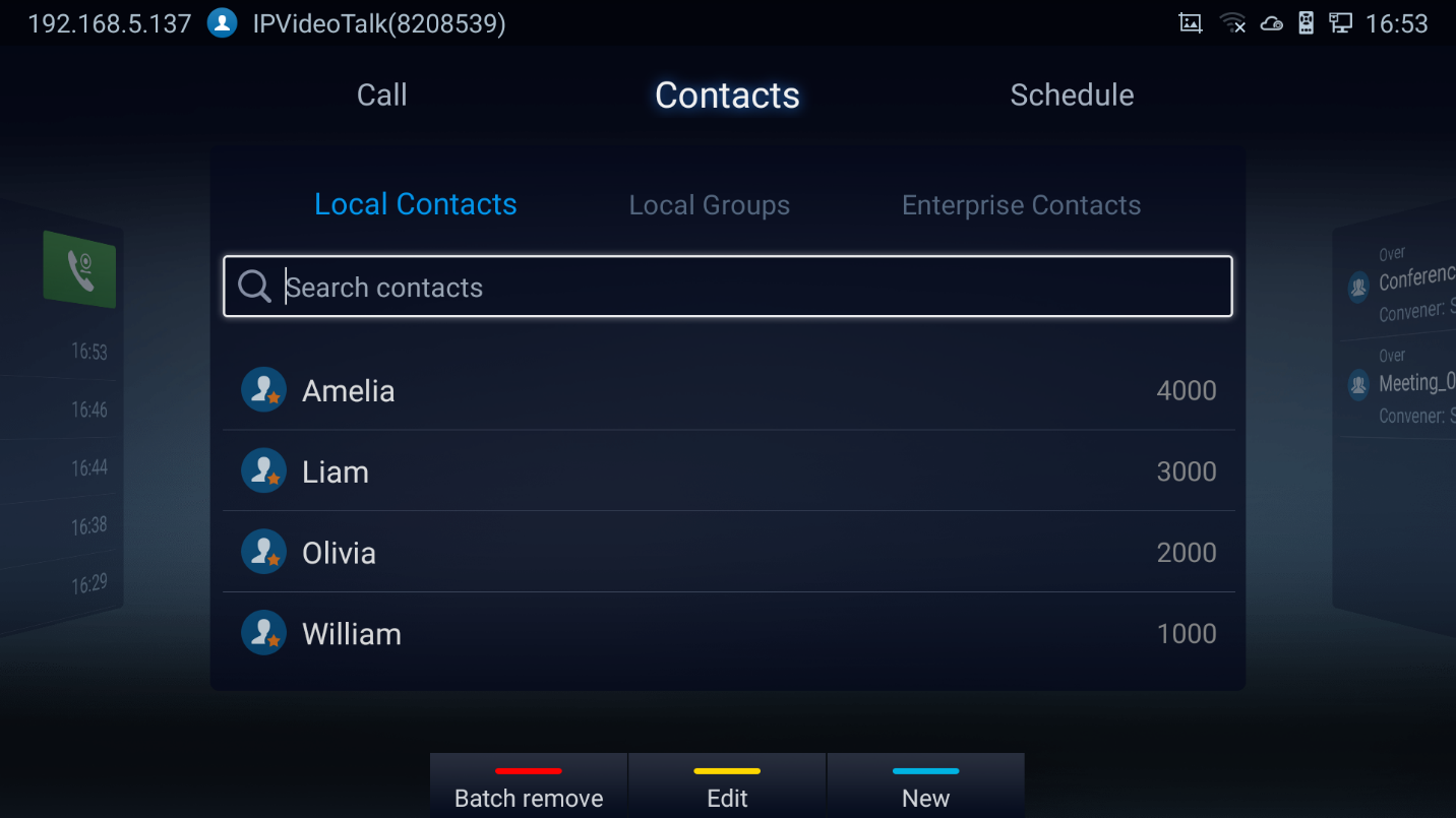
- Local Contacts: It is used to display all contacts.
- Local Groups: It is used to view groups. Select one group to view group details.
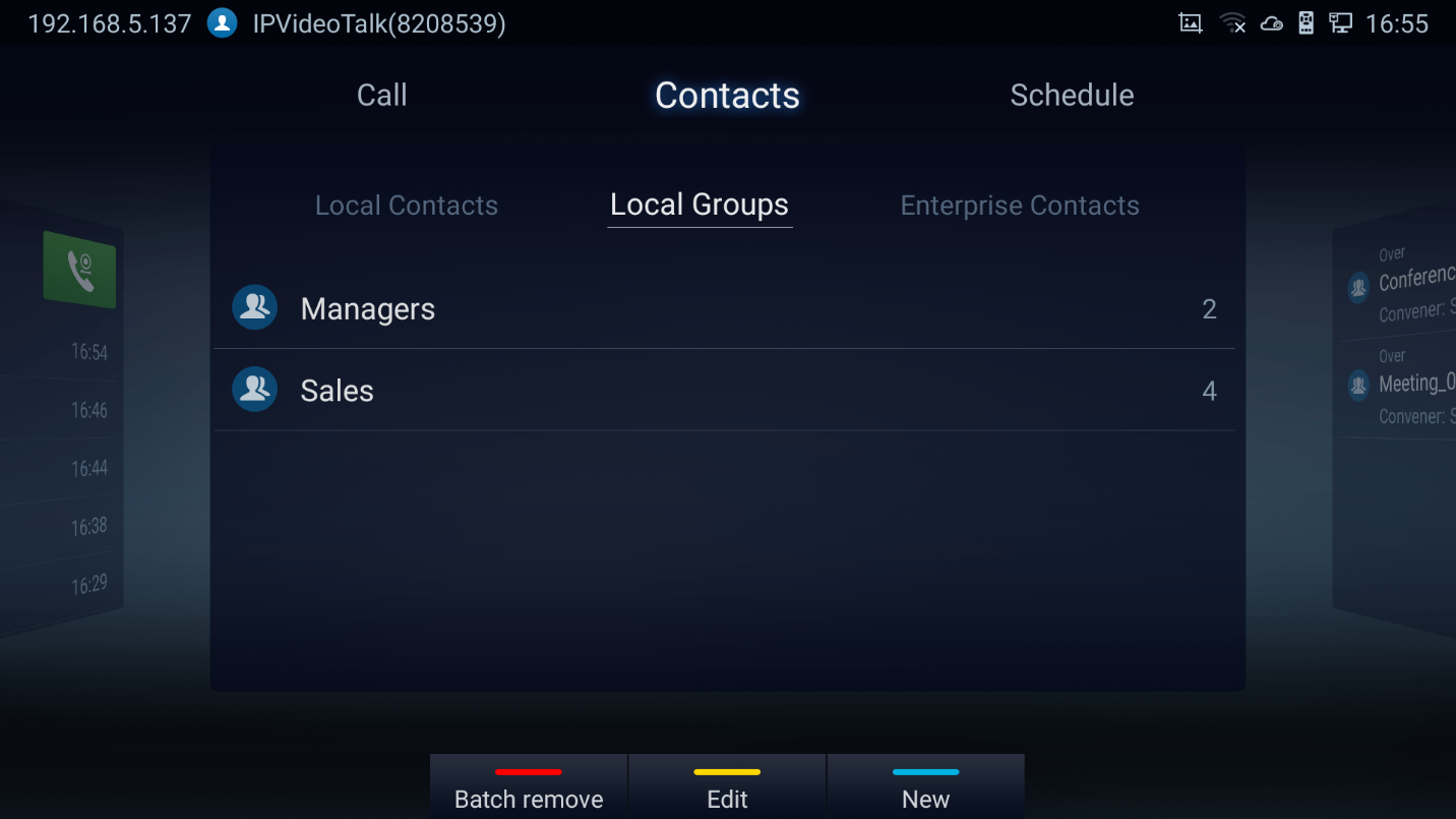
- Enterprise Contacts: It is used to view IPVideoTalk contacts
- Operations
- Search: Users could input keyword to search in the dialog. GVC3220 will display contacts automatically which is related to the search keyword. Fuzzy search and precise search are both supported.
- Call: Select the contact and press OK or on GVC3220 remote control or click on the screen button to dial the contact users would like to call.
- Add: Press
 shortcut key on the remote control to access New Contact screen, fill in contact information and press the yellow shortcut key on the remote control to save it.
- Edit: Press the yellow shortcut button on the remote control
- Batch remove: Press the red shortcut key to access the contact delete screen. Select the unwanted contacts and delete using the RED button.
- Contact Details: Select one contact and press “OK” key on the remote control to dial
Add Contact/Group
Add Single Contact
Follow the steps below to add one single contact:
- Press the blue shortcut key on GVC3220 remote control to access New Contact screen.
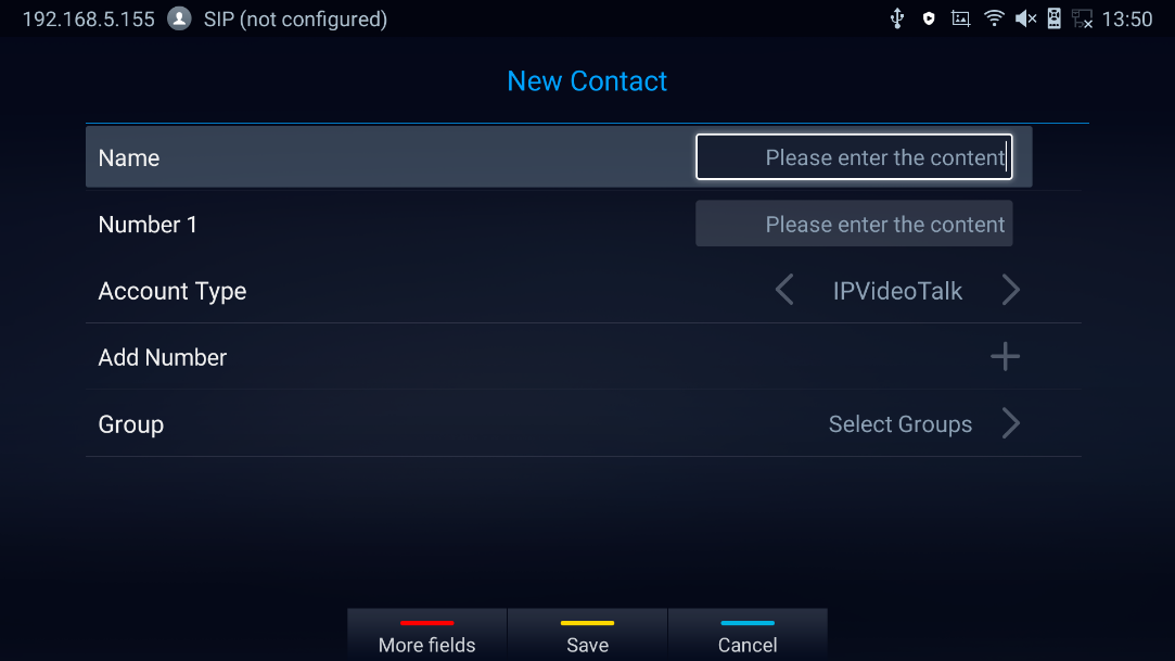
2. Enter the contact information.
Note: This screen allows assigning the Contact to a Local Group
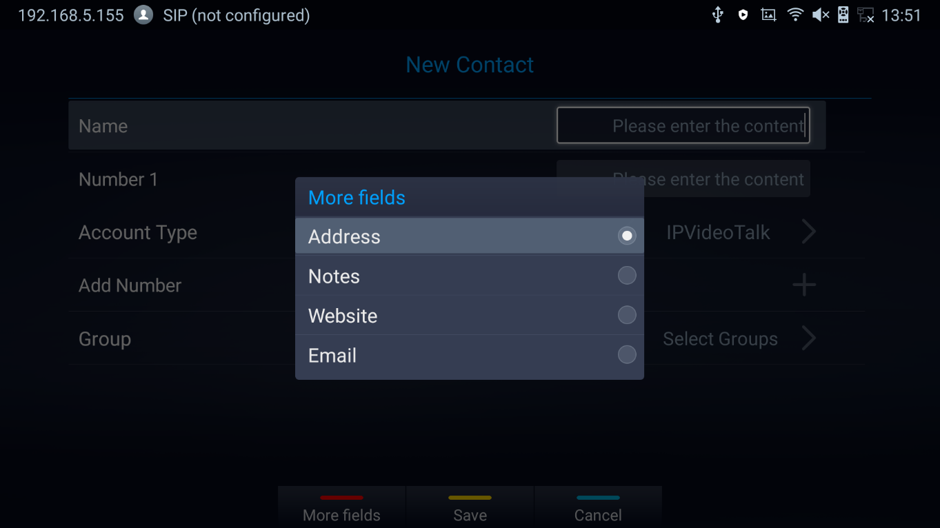
3. Press the red shortcut key to add more contact information.
4. Press the yellow shortcut key to save the contact information.
Add Group
Available under LCD Menu 🡺 Contacts 🡺 Local Groups 🡺 New.
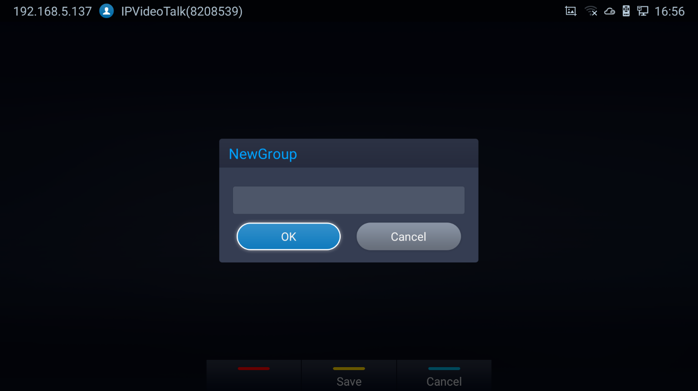
- Input a group name and tap on “OK” to add a new group.
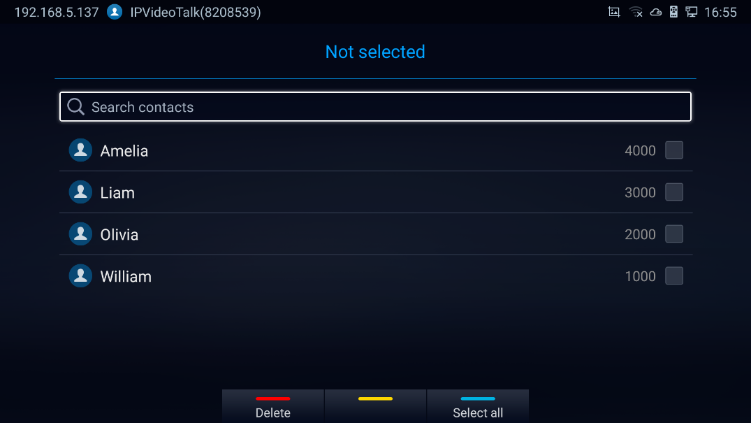
- Go to Contacts Screen to find the group you just added and access it.
- Press the YELLOW shortcut key on the remote control to access Groups editing screen.
- Select the contacts to add to this group.
- Press the YELLOW shortcut key on GVC3220 remote control to save.
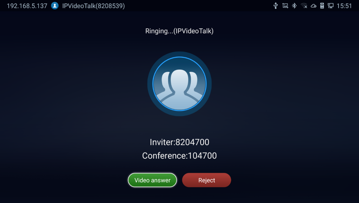
Answering a Call
When the device is in idle and there is an incoming video call made by SIP or IPVideoTalk account, the device will show the call screen as below:
-
 or “Pick up” button on the remote control. or select
 to reject the call.
- When there is an incoming call during an active call, users will hear a call waiting tone with the LCD displaying the caller name and ID for the incoming call.
 or “Pick up” button on the remote control. or select
 to reject the call.
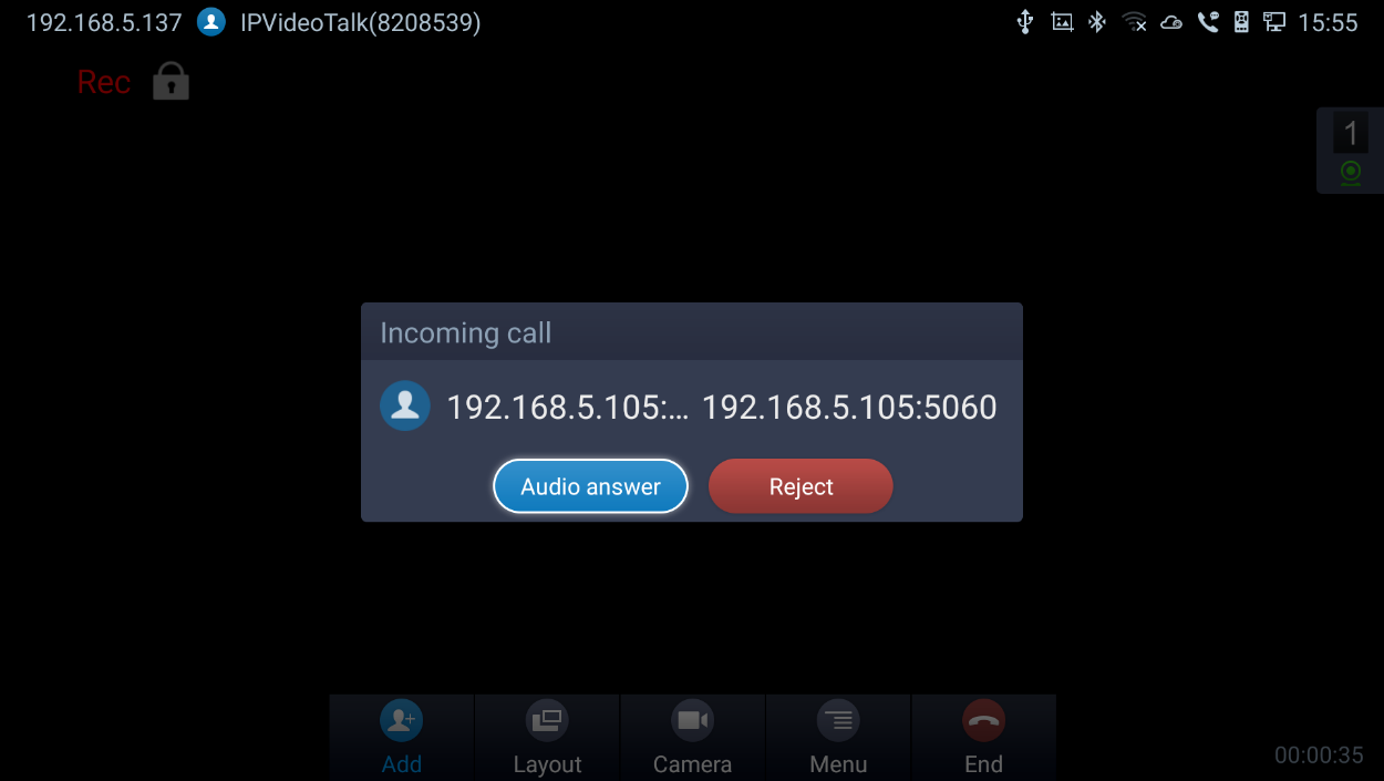
-
Users could select
 to answer with audio only.
 to answer with audio only.
Call Hold
During an active call, press HOLD button
 to put the call on hold.
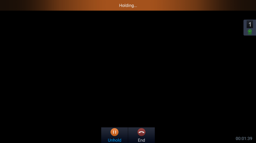
- The GVC3220 displays the ongoing conversation time on the bottom right of the screen
-
On the LCD display, click on
 to resume the call. Users can also click on
 or press on the remote control if they wish to end the call.
- If the current call is a video call, the screen will not display remote video when the call is on hold.
 to resume the call. Users can also click on
 or press on the remote control if they wish to end the call.
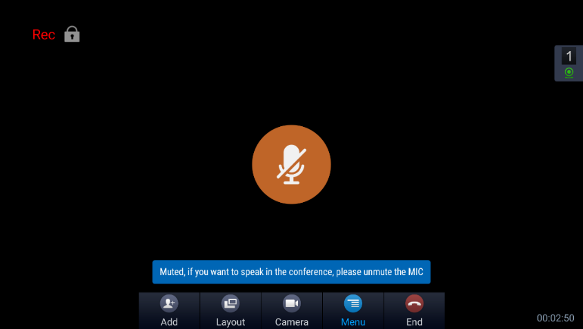
Mute Local Audio
During an active call, press the MUTE button to mute the call, press the button again to unmute the call.
OR, go to GVC3220 Call screen 🡺
 🡺
🡺

Call Recording
During an active call, users could record the video to the external SD card plugged into GVC3220. Once recorded, users can view the recorded video in Recorder application, and download the video from web UI 🡺 Maintenance 🡺 Recording. For more details, please refer to the chapter [Record].
-
During an active call, press the recording key
 on the remote control. A red Rec icon will show up on the upper left of the screen.
-
The recording files will be saved to the configured save path automatically when the call is finished. Users could also press
on the remote control to stop recording anytime.
OR, go to GVC3220 Call screen 🡺
 🡺
🡺
 (Audio & video) /
 (Audio only)
 when enabling IPVideoTalk recording,
  and
and  for video and audio recording, respectively.
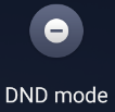
 DND (Do Not Disturb)
When DND is on, the incoming calls to GVC3220 will be blocked without ringing. Users could see the blocked calls in call history. Once it is enabled, the DND icon
![]() will be displayed in the status bar on the top of the screen.
will be displayed in the status bar on the top of the screen.
- When GVC3220 is in idle screen, users can press button on the remote control to turn on/off DND.
- When GVC3220 is in an active call, users could turn on/off DND in call screen. This will not affect the current call, and it will take effect starting from the next incoming call.
-
At any time, users could log in GVC3220 Call screen 🡺
 🡺
🡺
 to turn on/turn off DND.
- The status bar will notify that DND is activated:
 🡺
🡺
 to turn on/turn off DND.

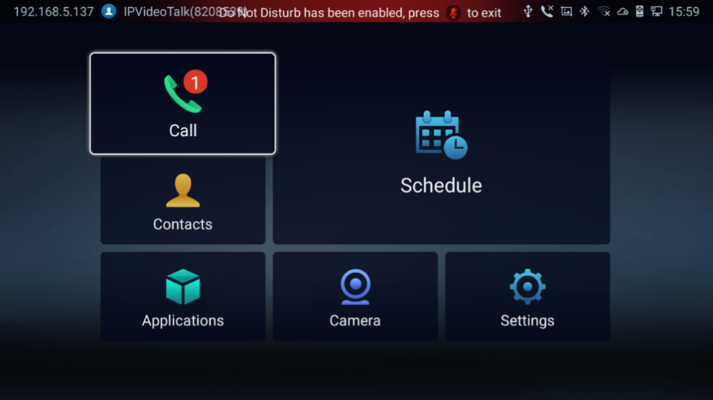
Missed Call
When there is a missed call, the call icon
 on home screen will show the number of missed calls. Once accessed the dial screen, the reminder icon will disappear.
Call Forward
Call forward (Unconditional/No Answer/Busy/Time Based) can be set up from web GUI. Log in GVC3220 web GUI and go to Account 🡺 SIP 🡺 Call settings. For details, please refer to “GVC3220 Administration Guide”.
Conference
Device Layout
GVC3220 supports up to 5-way 1080P video conferences. it can either be the host to initiate a conference or join other conferences as a member.
Users can connect multiple HDMI output devices for conference. HDMI 1 interface is the primary output when plugging in multiple HDMI display devices. The device connected to HDMI 1 interface will display local site by default while other devices automatically display remote sites. If the HDMI IN device is plugged in to GVC3220, the device connected to HDMI 1 interface displays presentation of HDMI input while other devices will display video view.
During a conference, user can tap on button on GVC3220 remote control to go back to HOME screen, with the conference video displayed in the background.
Initiating Conference
The conference can be initiated in multiple ways:
- From Call Screen:
- Access the call screen, enter the numbers in the text box or select members from the list below.
- Press on the remote control or click on “Call” button on the screen to dial out.
- From Schedule:
For more details, please refer to section [Schedule] from this document.
Answering an Incoming Call in Conference
You can specify how your GVC3220 handles incoming calls. Depending on your configuration, your GVC3220 answers a call automatically or prompts you to answer a call manually:
- Log in GVC3220 web GUI and go to Account 🡺 SIP/H323 🡺 Call settings and set “Auto-answer” option to “Yes”. All incoming calls will be answered automatically. If it is a video call, it will be answered with video as well.
- If “Auto Answer” is set to “No”, users will need to select to answer with video manually, audio or reject the call using the remote control on the LCD prompt.
- If the conference host answers the call, the caller will join into the current active conference.
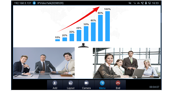
Conference Management
The following figure shows a 3-way conference: conference screenshot
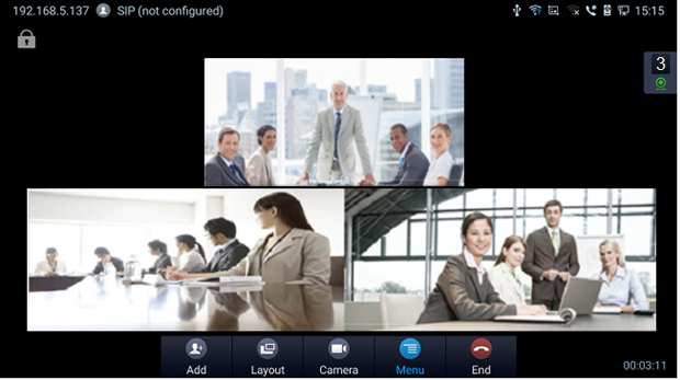
On the bottom of the call screen, users will see a list of icons for menu options. This menu will be automatically hidden if there is no operation in 5 seconds. Press any key to bring up the menu options again.
Here are the functions for each icon.
Icons | Name | Definitions | |

| Add Member | Access dial screen and add more numbers to join conference. | |

| Layout | Adjust the layout for the video display for video call. The layout options might vary depending on how many video participants are in the call, how many HDMI outputs are connected and whether presentation is turned on or not. The user can choose to adjust “Local Layout” in order to choose a layout for its own GVC3220, or to adjust “Cloud Layout” to choose a layout that will be shown for all the participants of the conference (this feature needs to be supported on the server side). For example, in a two-way video call on GVC3220 which has one HDMI output connected, after pressing “Layout” icon, users will see options “Average”, “Remote (Local)”, “Local (Remote)”, “Remote” and “Local”. | |

| Camera | Open Camera Control | |

| Menu | 
| Enable/Disable GVC3220 audio stream. |

| Enable/Disable GVC3220 video stream. | ||

| Control video and audio for the host (Me) or other conference members (Participants). It includes the following options:
| ||

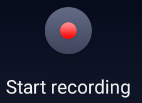
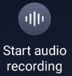
| Start/Stop recording the ongoing conference. The recording files will be available from [Record] application. | ||

| Start/Stop Audio recording the ongoing conference. | ||

| Pause/resume conference. Once the conference is paused, the device will stop sending local video/audio to the remote parties. | ||

| Enable or disable DND. | ||

| To enter DTMF digits during the call. | ||

| This is to set a PIN code to lock this conference call. Once the conference call is locked, the caller who wants to join this conference by calling the conference host must enter the PIN code. | ||

| Display conference information such as Subject, Meeting ID, Organizer, URL, Host Code and Server Area | ||

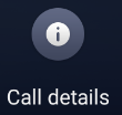
| Display call details such as video packet loss rate, video bit rate, video frame rate, video codec, video resolution, audio packet loss rate, audio bit rate and audio codec for both sending and receiving parties. | ||

| Click to raise hand | ||

| Click to put hand down | ||

| End | End conference and go back to home screen. |
 – The selected party will not be heard by other parties.
 – The video call with the selected party will turn into audio call. If the user clicks on this icon again, a video invitation will be sent to this party. The party has to accept the video request in order to see the video again.
 – Lower the hand of a user (from the participants list) or lower all hands (from Conf Control).
 – Delete member from the conference
 – Turn Off /On the Local Camera
- If the remote party is also a GVC3220, you can press the camera key on the remote control to control PTZ device for the remote party.
- During an active conference call, if there is a new member joining conference, an outgoing call failed or a member hanging up, there will be a prompt box on the left side of the conference screen showing notifications. The notification prompt will be hidden automatically if there is no new notification in 2 seconds.
- On the right side of the video conference screen, users can see member status such as audio/video calls, or whether if the call is being muted.
The current line is in an audio call. | The current line is being muted. | ||
The current line is in a video call. | The current line is not connected. |
-
On the upper left side of the video conference screen, users can see an icon
 to indicate network unstable condition, which means the current network condition is not good enough for the video call using the selected resolution/bit rate.
Invite Members to Conference
Users could use one of the following ways to add members:
-
Access the dial screen by clicking on the ADD icon
 on conference screen. Then, enter the number to dial out. Once the member answers the call, it will be connected into the conference automatically.
- When GVC3220 is on conference screen, press on the remote control to access the call screen. Then, enter the number to dial out. Once the member answers the call, it will be connected into the conference automatically.
- The member calls the conference number. If the host answers the call, the member will be added into conference automatically.
 on conference screen. Then, enter the number to dial out. Once the member answers the call, it will be connected into the conference automatically.
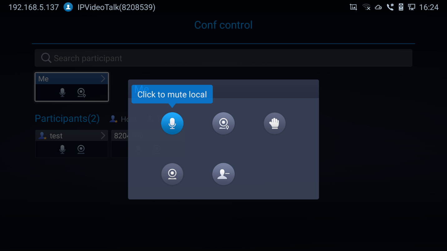
Conference Control
Tap
 on to make operations such as mute, disable sound, camera control and suspend video. The conference control screen is as shown below:
- Use Up/Down navigation keys on GVC3220 remote control to select conference member.
- Use Left/Right navigation keys on GVC3220 remote control to make operations, press “OK” key to confirm the operation, press “OK” key again to cancel, e.g. tap on to mute one member and the icon will turn to tap on it again to restore.
- To remove a member from the conference, click on the DELETE icon on conference screen. Select the member from the member list and press “OK” key to delete it.
Pause Conference
The video will be stopped if the conference is paused. You will not see the video view of the members and the other members will not see your video either.
Conference Layout
During a video conference, users can customize screen layout when using multiple connected HDMI outputs, to specify particular video feeds to be displayed on each screen.
Under GVC Call screen 🡺 Layout, users can choose the most convenient layout.
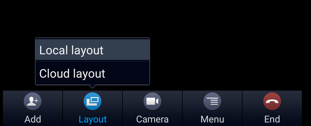
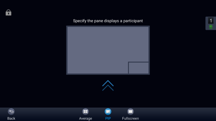
- Local Layout: Users can choose the local layout that will be shown only on the GVC3220 where the local layout was adjusted, and not for all the participants. The available local layouts are: Average, PIP (Picture in picture) and Full screen display.
- Cloud Layout: The host user can choose a cloud layout to be used for the whole conference and will be shown for users as well (this feature needs to be supported by the server as well). The available Cloud Layouts are: Tile, Solo, 1+3, 1+5, 1+7, Speaker.
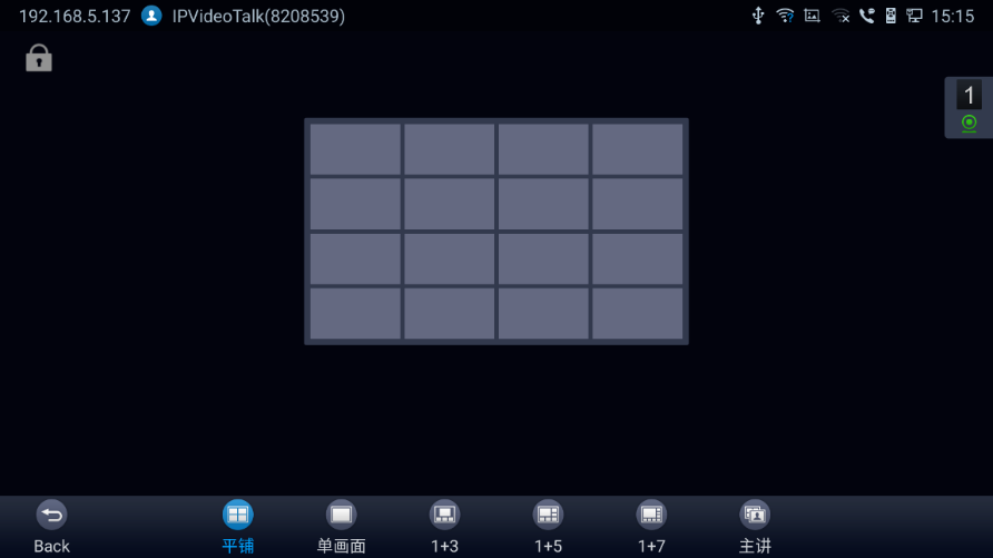
- When solo mode meeting layout is set: Users could specify a pane to display a certain participant.
- When Speaker mode meeting layout is set: Users could specify a pane to display a certain participant. The speaker can view all participants video images, and the participants can only view the speaker’s video image.
- Focus 1+N: There are 3 modes for users: “1+3” layout, “1+5” layout, and “1+7” layout, which means one large video image with N smaller video images (polling mode).
Presentation Sharing
GVC3220 supports dual stream video, with the presentation sharing function, you can connect HDMI input devices or wireless devices (that support screen mirroring). And share the input sources with remote parties while they can still view the local video.
To share a presentation please follow the below steps:
- Link the GVC to your presentation device
- Cable link: Users can connect a PC/Laptop to the HDMI in port
- Wireless link: Users can enable Wi-Fi and use Wi-Fi Projection option under Settings 🡺 Network
For more information please refer to [Wireless Projection] section in this document.
- Share screen during an ongoing conference call
- Users can simply press the presentation button on the Remote control. Or, click on presentation from the call menu
- All the participants should be able to visualize the mirrored screen as shown on the figure below.
Web GUI Sharing
The GVC3220 allows sharing the management device screen during a conference call. This applies to any device from where you can log in and access the GVC3220 web configuration interface. The feature can be enabled by proceeding as follows:
- Set HTTPS as Web Access Mode under GUI 🡺 System Settings 🡺 Security Settings.
- During an ongoing conference call, click “Share Screen” option from the Web GUI tool bar.

- A pop-up window will allow you to choose which screen to share
- The GVC3220 will include two of the available screens, open browser and running applications on the device from where you have accessed the Web GUI.
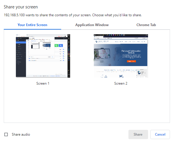
- Audio sharing can be enabled/disabled at the bottom of the pop-up window
- Complete your selection. Then, click on “Share”.
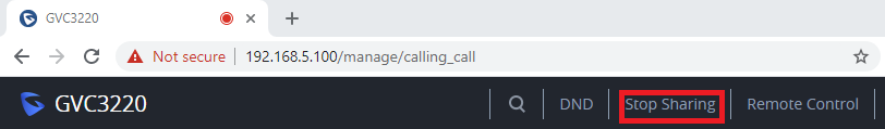
- Notice the RED ball on the browser window, indicating that screen sharing is enabled
- Stop the Web GUI screen sharing at any given moment by pressing the related button from the tool bar.
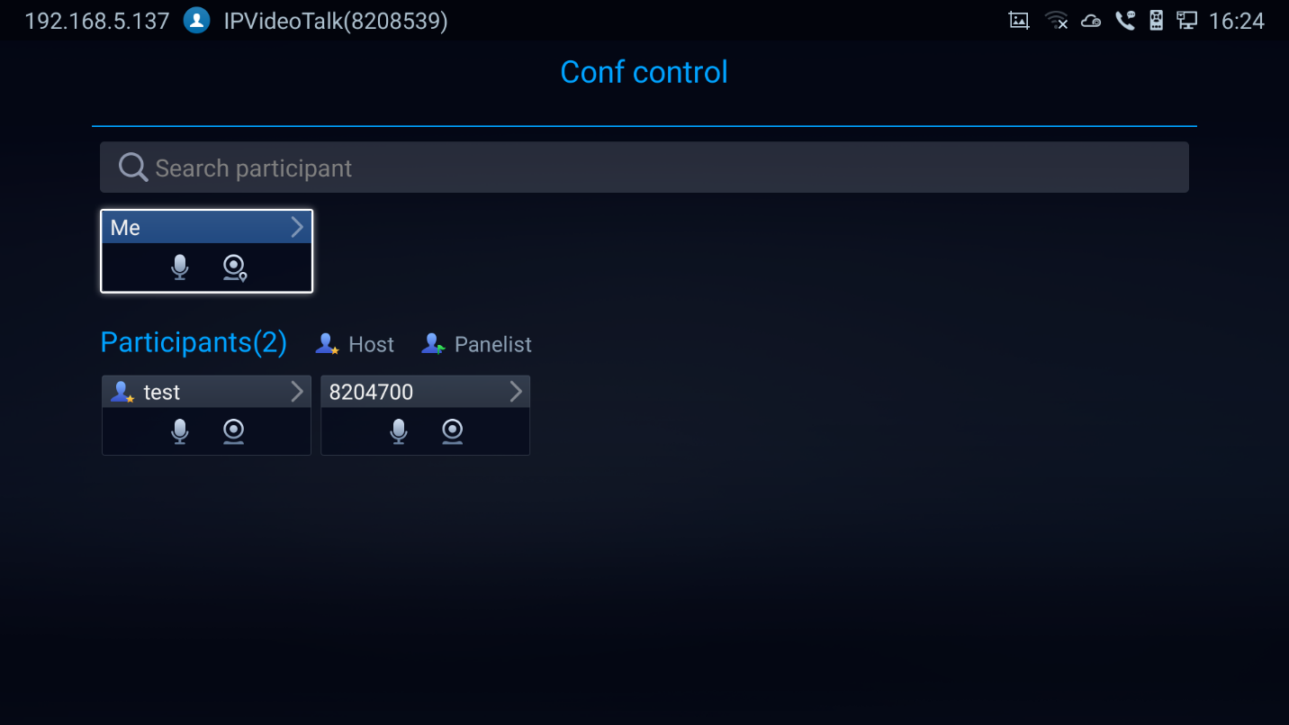
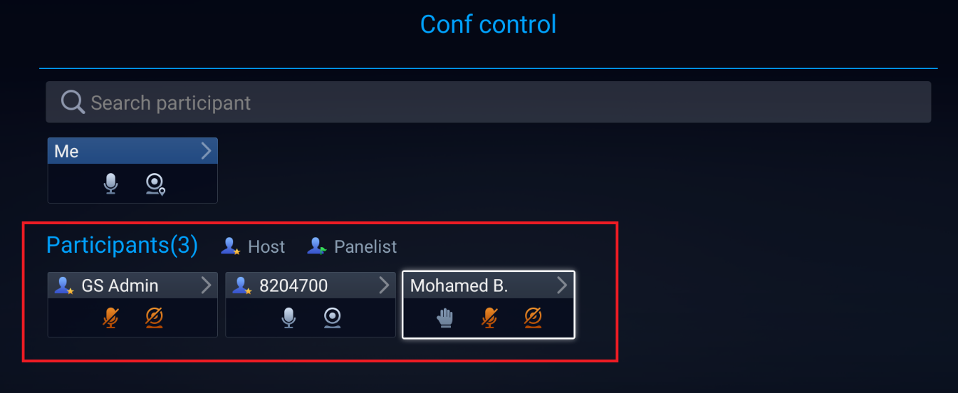
Participants List
Users could check all participants in the current IPVideoTalk meeting. If the meeting host does not allow the participants to check all members, the participants cannot see all members in the meeting.
During IPVideoTalk meeting, click on “Conf control”
![]() and GVC3220 will show all participants in the current IPVideoTalk meeting, including all participants with all types of clients.
and GVC3220 will show all participants in the current IPVideoTalk meeting, including all participants with all types of clients.
Call Details
Users could view audio and video details of the conference members. On the conference screen, click on Menu and select
Conference Lock
Users could lock/unlock the scheduled conference. Once it is locked, the other incoming calls will not be able to join the conference. The locked scheduled conference will display
 icon on the screen.
Open DTMF
Users can dial DTMF during a conference.
-
On GVC3220 remote control, click on Menu button then select
 on the conference screen to bring up the DTMF input screen.
 on the conference screen to bring up the DTMF input screen.
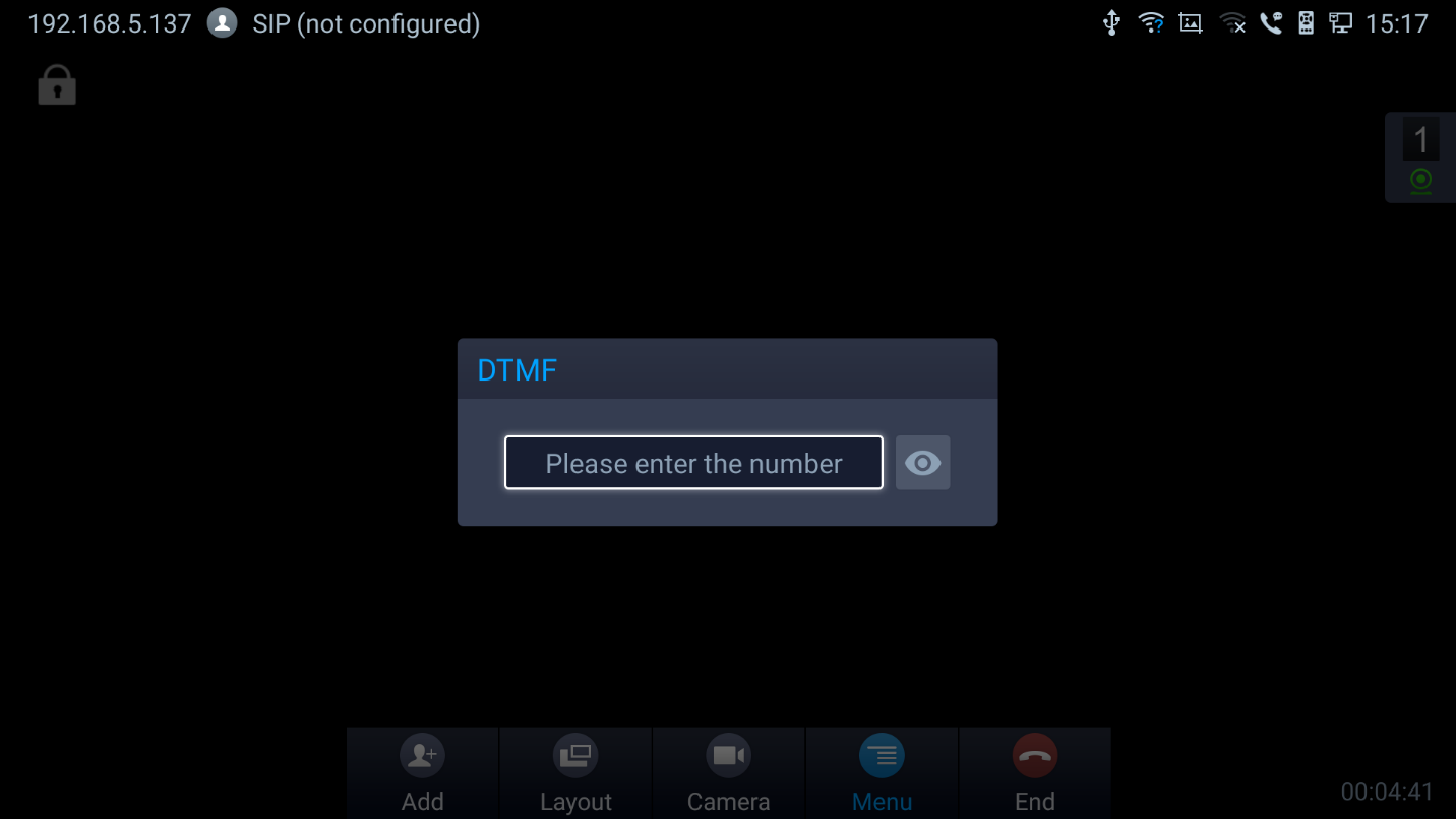
- Press the digital keys on the remote control to input DTMF. Press to cancel the operation if needed.
PIN Code
During the conference call, the conference host can set a PIN code to lock the call. Once the conference call is locked, the caller who wants to join this conference by calling the conference host must enter the PIN code.
Here is how to use PIN code to lock the conference call:
- During the call, in the GVC3220 display LCD call screen Click the Menu bottom then
 .
. - Enter the PIN Code to lock the conference call. If it is empty, the conference call is not locked. Click on OK to confirm.
 .
. 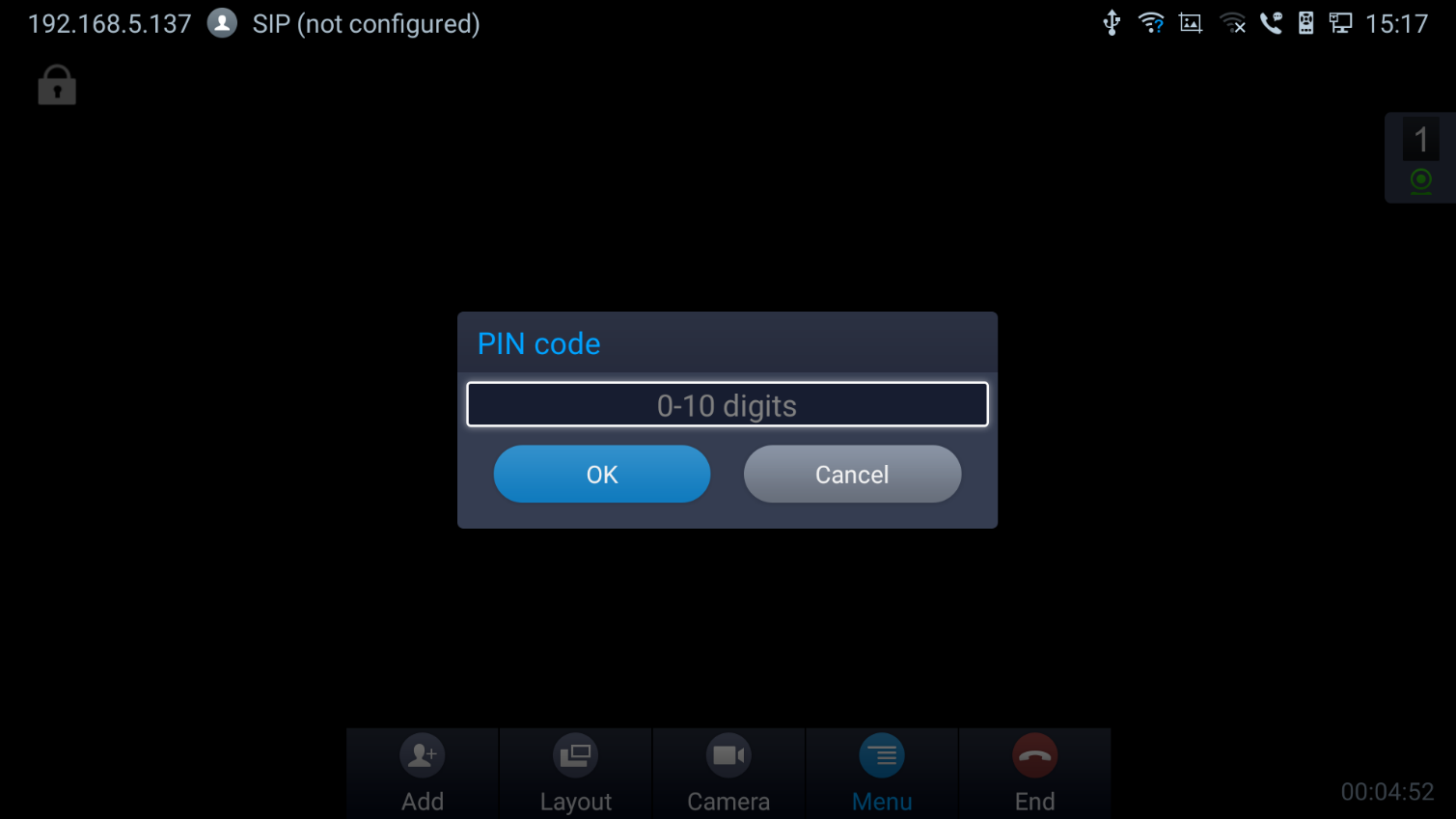
- Now the conference call is locked. If someone wants to join the conference call by calling this GVC3220, the same PIN code will be required to be entered before the call goes through.
Here is an example on how to use PIN code to enter the locked conference call:
- Make a video call to the GVC3220 that has locks the conference call from another GVC3220.
- The GVC3220 caller will show a video windows with voice prompt asking for PIN code.
- On the GVC3220 caller’s call screen Menu
 🡺 Dial DTMF
  . Then input the DTMF with PIN code followed by #.
 - The GVC3220 caller joins the conference call after entering correct PIN code in DTMF.
 🡺 Dial DTMF
  . Then input the DTMF with PIN code followed by #.
 FECC – Camera Control in Conference
During the video call, if the local party (GVC3220) and remote party support FECC, the remote camera can be controlled on the GVC3220.
Here is how to use FECC on the GVC3220 to control remote party’s camera:
- Make sure the GVC3220 and the remote party support FECC and it is enabled on both parties. For GVC3220, FECC setting is under web UI 🡺 Account 🡺 SIP/Bluejeans/Zoom 🡺 Codec Settings: “Enable FECC”. If the remote party is another vendor’s video device, please check the documentation from the vendor to enable FECC.
- Establish video call between GVC3220 and the remote party.
- On the GVC3220 remote control, press the camera button
 and the following prompt pops up on GVC3220 display device.
 and the following prompt pops up on GVC3220 display device.
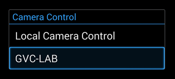
4. Use UP/DOWN/OK navigation keys on the GVC3220 remote control to select the remote party, e.g., GVC-LAB in the above figure. This will bring up camera control interface.
5. On the GVC3220 remote control, press the navigation keys and zoom in/zoom out buttons to adjust camera.
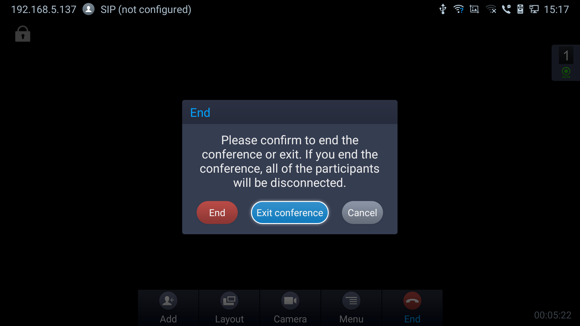
End Conference
To end the conference, tap on END button
 or press key on GVC3220 remote control to either “Exit Conference” or “End Conference”. If GVC3220 is the conference host:
- Select “Exit conference” so that the GVC host will leave the conference itself while the IPVT conference will still be going on. The GVC host can join back the conference by pressing the remote control’s button in order to continue/end the meeting.
- Select “End conference” so that the IPVT conference will be ended and all of the other participants will be disconnected from the IPVT server.
If the conference member hangs up the call, it will be disconnected from the conference, but other parties in the conference will stay in the conference.
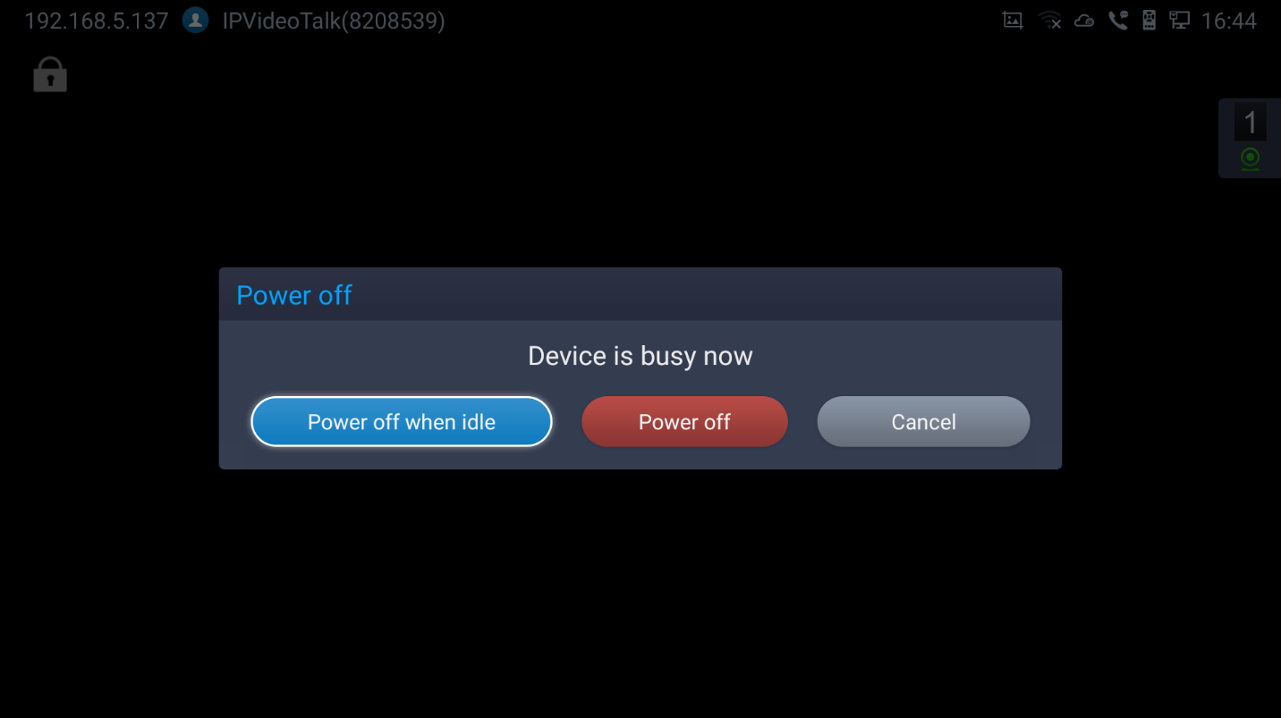
Power Off During a Conference Call
During the meeting, if the user presses Power ON/OFF button, a new dialog will be prompted that allows user to end the current call and shutdown GVC3220 immediately.
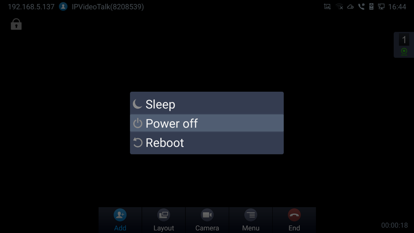
Choose “Power off” to end the conference call and power off the GVC3220 immediately or choose “Power off when idle” to shut down the device when the conference call is ended.
Schedule
Schedule feature allows users to set a specific time to host a conference in advance, with conference reminder and members.
Follow one of the ways below to access schedule conference screen:
-
On the home screen, click on
 “Schedule” button.
 “Schedule” button.
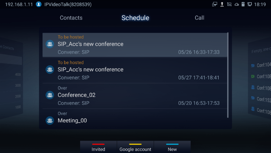
- Users will see the scheduled conferences (after the current time) in the schedule screen. Select one conference entry to view details.
-
User may proceed as follows:
-
Press
 to switch between “Invited” and “Mine”, where it shows meetings where the GVC is invited (participant) to and meetings to host.
-
Press
 to access google account setting
-
Press
 to switch between “Invited” and “Mine”, where it shows meetings where the GVC is invited (participant) to and meetings to host.
 to access google account setting
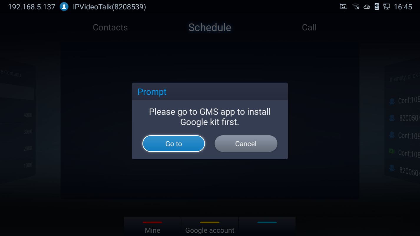
Note: You will be asked to install GMS App Google Kit first if not available. Which is a collection of Google applications and APIs that help support functionality across the device. The apps are working together seamlessly to ensure the GVC android device provides a great user experience.
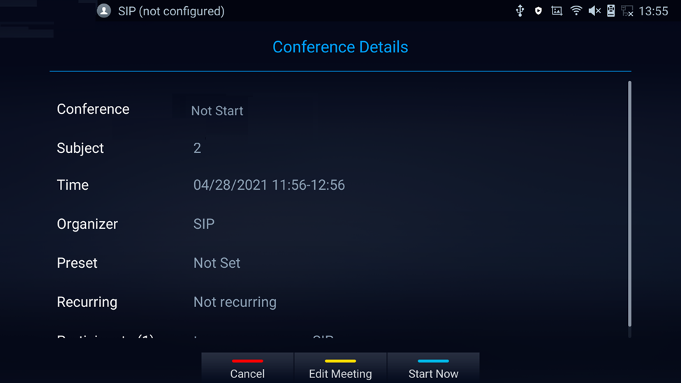
View Conference Details
Users could view scheduled conference details after the current time. Select one conference and press “OK” key on GVC3220 remote control to view conference details.
- If the Conference was already established: Schedule status is “Over”, the user can then choose to “Delete” or Reschedule the conference.

- If the Conference was not established yet: Schedule status is “Not Start”, the user can then choose “Cancel” to delete it, “Edit” or “Start” the conference.
Add Scheduled Conference
Follow the steps below to add a scheduled conference:
-
On the home screen, select
to access schedule screen.
-
On GVC3220 remote control, press the
 shortcut key to create a new conference.
 to access schedule screen.
 shortcut key to create a new conference.
- Fill in conference name, members, start time, conference duration and etc.
- Press the yellow shortcut key on the remote control to save the scheduled conference.
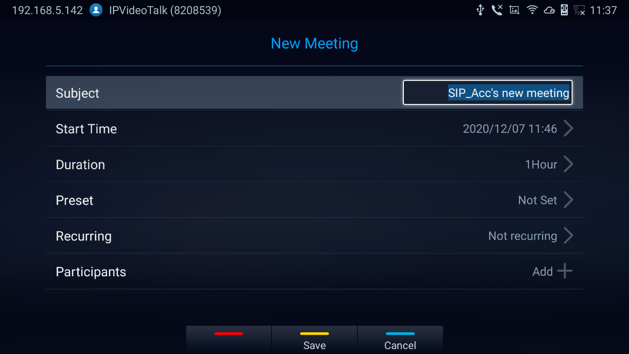
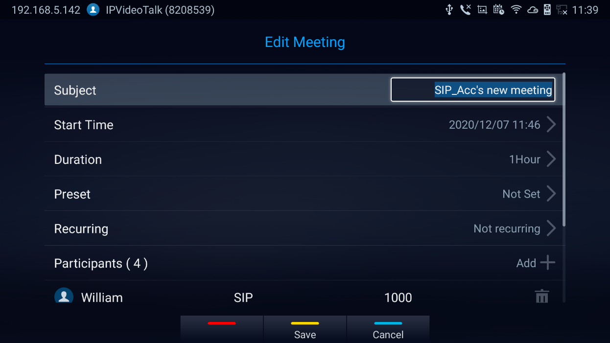
Table 12: GVC3220 Add Conference Parameters
Parameters | Descriptions |
Subject | It is used to set the conference name to identify this conference. |
Start Time | It is used to configure the start time of the conference. |
Duration | It is used to configure how long the conference is supposed to last. |
Preset | It is used to select a camera preset when the scheduled conference starts, the GVC3220’s camera will be automatically placed to the preset position. Click on Conference preset and select “Custom” to be redirected to preset setting interface to configure and set a preset. Default is “Not set”. |
Recurring | Users could select recurring for the scheduled conference, to repeat the conference depending on the chosen option. The recurring options are:
|
Members | Click on "Add" button to access the Add Member screen. Users can add one member or a group of members. Press the yellow key on the remote control to save and go back to schedule screen. Up to 8 members can be added. |
Edit Scheduled Conference
Follow the steps below to edit scheduled conference:
- Access conference schedule screen and select the conference entry users would like to edit.
- Select the conference and press YELLOW shortcut key from the GVC3220 remote control to access edit screen.
- Press the yellow shortcut key on the remote control to save changes and go back to schedule screen.
Voicemail
When there is a new voicemail, the voice mail icon
![]() will show up as a notification in the status bar. Users could login the web UI 🡺 Account 🡺 SIP/IPVideoTalk/H323 🡺 General Settings to configure the access number for the voicemail.
will show up as a notification in the status bar. Users could login the web UI 🡺 Account 🡺 SIP/IPVideoTalk/H323 🡺 General Settings to configure the access number for the voicemail.
Follow the steps below to access voicemail:
- Access the dial screen and input voicemail access number.
-
Press on GVC3220 remote control or click on button
 on the call screen to dial into the voicemail box.
- Follow the Interactive Voice Response (IVR) for the message retrieval process.
 on the call screen to dial into the voicemail box.
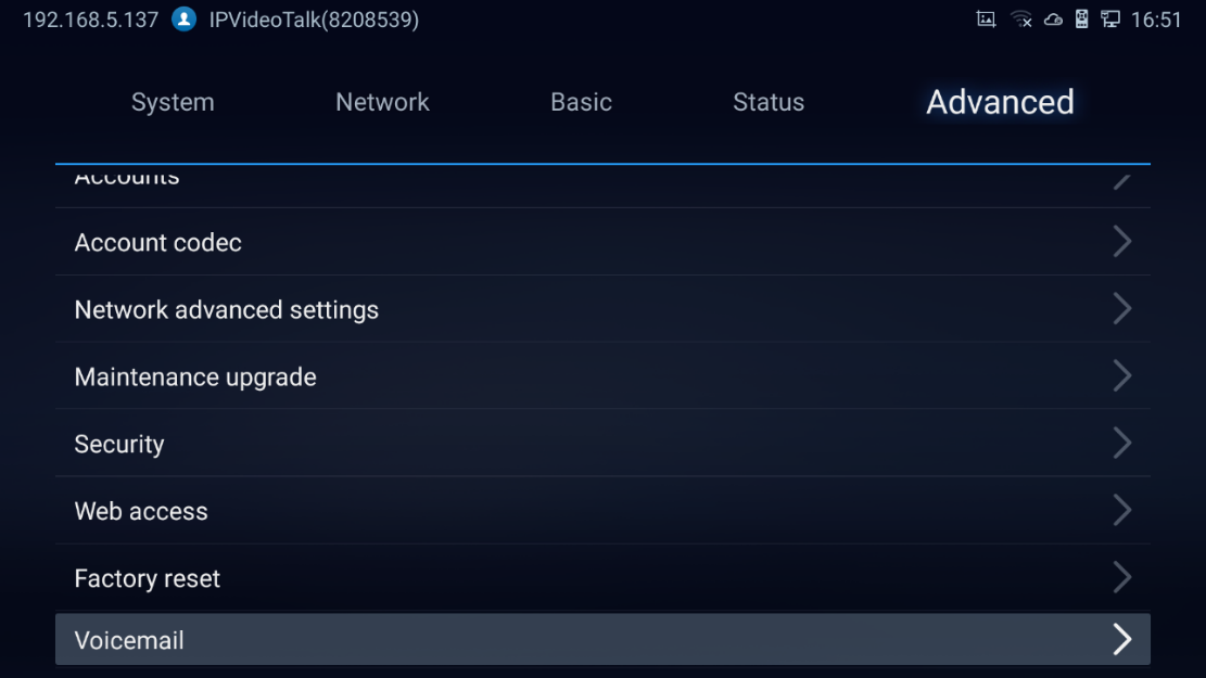
Voice mail is accessible under Settings 🡺 Advanced 🡺 Voicemail.
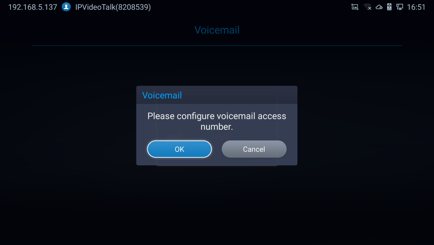
- The users will be asked to configure the Voicemail Access Number before being able to access:
Call Features
The GVC3220 support traditional and advanced telephony features including caller ID, caller ID with caller Name, call waiting, call forward and etc. for the SIP account. Before using the following feature code, please make sure “Enable Call Features” option is set to “Yes” under web GUI 🡺 Account 🡺 SIP 🡺 Call Settings. Please note this feature does not apply to IPVideoTalk account or H.323/BlueJeans/Zoom account.
Table 13: GVC3220 Feature Code for SIP Account
Feature Code | Description |
*01 | Use Preferred Codec (per call). - Dial *01 followed by the preferred codec code and the phone number. - The device will use this codec in the INVITE SDP as the first codec when initiating the call.
For example, if the user would like to use PCMA as the preferred codec to call phone number 334455, enter *017111334455. Please note the actual codec being used might be different, which is the negotiation result between the endpoints and SIP server. |
*02 | Force Codec (per call). - Dial *01 followed by the preferred codec code and the phone number. - The device will use this codec in the INVITE SDP as the first codec when initiating the call.
For example, if the user would like to force using PCMA to call phone number 334455, enter *017111334455. |
*16 | Enable and force SRTP for all subsequent calls. |
*17 | Disable SRTP for all subsequent calls. |
*18 | Enable SRTP per call. |
*19 | Disable SRTP per call. |
*30 | Block Caller ID (for all subsequent calls).
|
*31 | Send Caller ID (for all subsequent calls).
|
*50 | Disable Call Waiting.
|
*51 | Enable Call Waiting.
|
*67 | Block Caller ID (per call).
|
*82 | Send Caller ID (per call).
|
*70 | Disable Call Waiting (per Call).
|
*71 | Enable Call Waiting (per Call).
|
*72 | Unconditional Call Forward. To set up unconditional call forward:
|
*73 | Cancel Unconditional Call Forward. To cancel the unconditional call forward:
|
*74 | Paging Call.
|
*83 | Force Audio Calling (per call).
|
*84 | Force Video Calling (per call).
|
*90 | Busy Call Forward. To set up busy call forward:
|
*91 | Cancel Busy Call Forward. To cancel the “busy call forward”:
|
*92 | Enable Call Forward No Answer. To set up Call Forward No Answer:
|
*93 | Cancel Call Forward No Answer. To cancel Call, Forward No Answer:
|
ADDITIONAL FUNCTIONS
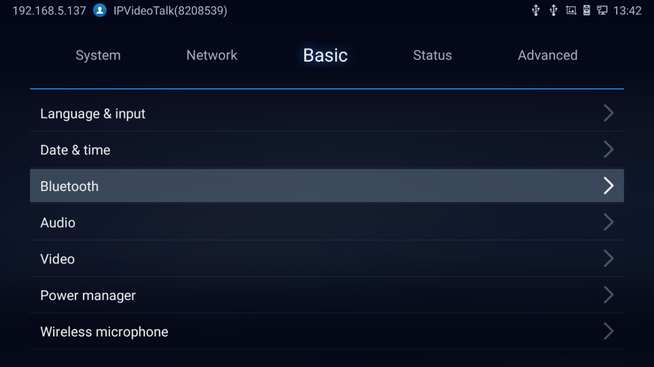
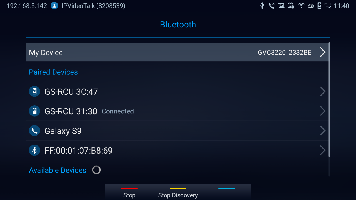
Bluetooth
On GVC3220, Bluetooth is enabled by default. Users could connect Bluetooth by remote control, send or receive files to cellphone, or use Bluetooth speaker and etc. on GVC3220.
Notes:
-
Press
 to Cancel the Bluetooth connection
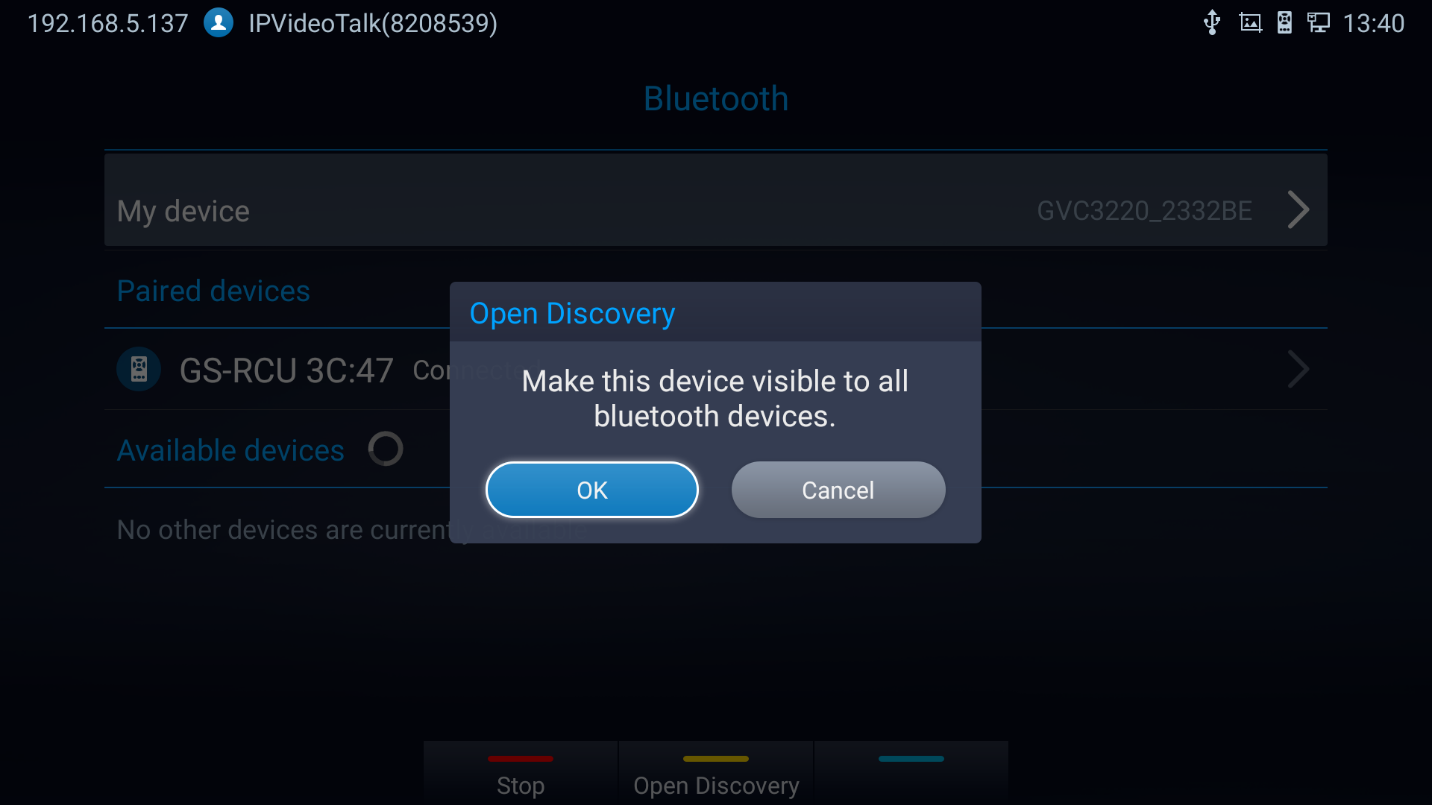
-
Press
 to allow the GVC3220 to be visible for other Bluetooth devices. Confirm by pressing OK on the pop window:
 to Cancel the Bluetooth connection
 to allow the GVC3220 to be visible for other Bluetooth devices. Confirm by pressing OK on the pop window:
Using Bluetooth Remote Control
Users could use GVC3220 Bluetooth remote control that comes with the GVC3220 packaging to control and configure a GVC3220. When the GVC3220 boots up for the first time, a setup wizard will guide the users to pair and connect the remote control to the GVC3220. Or you can refer to the steps below:
- Open the battery cover on the back of the remote control. Place four AAA batteries properly and put the cover back on, the remote control can be used normally. At this time, the remote control is in infrared mode, and the LED light of the remote control shows green color when used.
- You can also choose to pair the remote control with GVC3220 main case according to the interface prompts: Please align the remote control to the device, long press OK and 5 on the remote control to connect to the GVC, when the LED on the top of the remote control flashes, the keys can be released. At this time, the remote control will be automatically paired and connected, and the LED light of the remote control shows blue color when used.
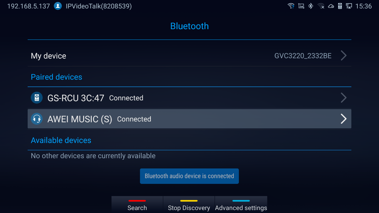
Using Bluetooth Headset
Once the Bluetooth headset is connected with GVC3220, it will automatically use Bluetooth headset for calls.
GVC Remote Client Application
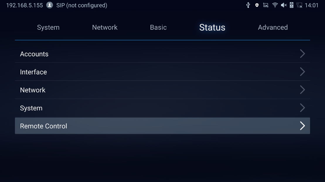
Besides using GVC3220 Bluetooth remote control in the package, users could also download the Grandstream GVC Remote Client application, and install it on an Android device. GVC3220 remote control application is used via Bluetooth protocol. Follow the steps below to install the remote control application:
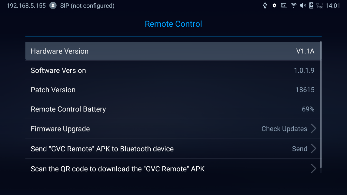
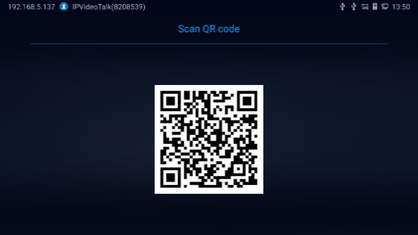
- Please go to GVC3220 LCD menu 🡺 Settings 🡺 Status 🡺 Remote control to send GVC Remote apk to Bluetooth device or scan the QR code.
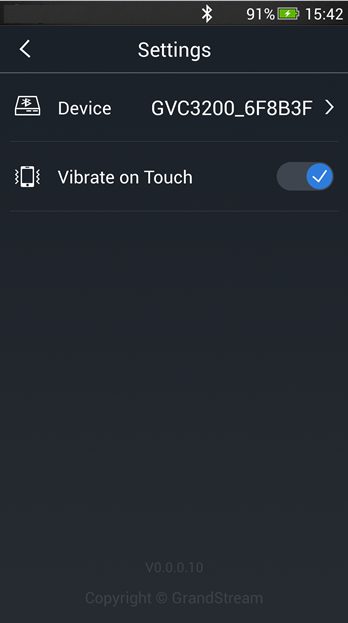
2. Once GVC Remote app is installed on your Android device, open it and access settings screen.
3. Select the GVC3220 device that users would like to connect to. Each discovered GVC3220 could be distinguished by the last 6 digits of its MAC address.
4. Pair GVC Remote app with GVC3220 via Bluetooth. Users might see prompt on GVC3220, and Android device to confirm the passcode during pairing and connection process.
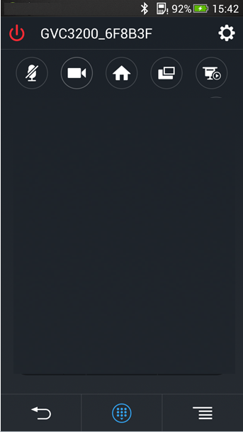
5. After pairing and connecting the remote control application, users can use the keys and options on the Android device touch screen to control GVC3220.
-
Tap on button
 at the upper right corner to access settings screen as the left figure shows above.
-
Tap on button
 to go back to home screen as the figure in the middle shows above.
-
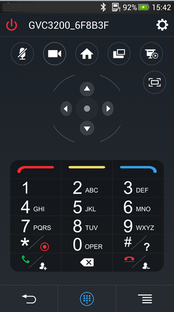
Tap on button
 to bring up navigation panel and digital keyboard as the right figure shows above, tap on
 again to hide the keyboard.
Note: Users can Send the GVC Remote apk using Bluetooth feature:
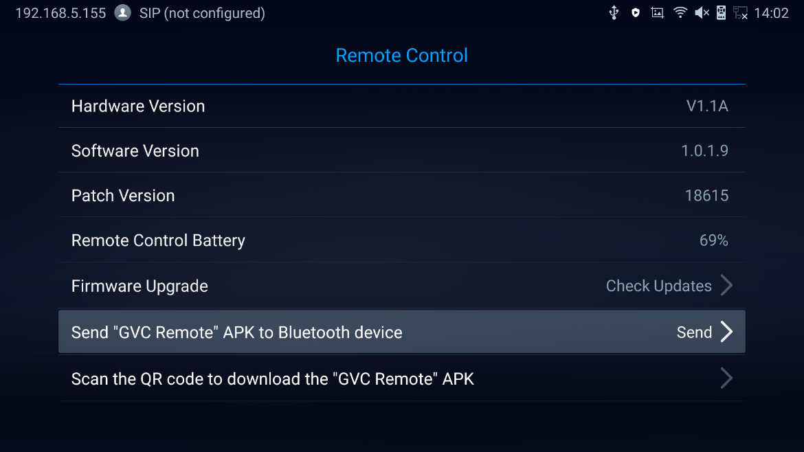
- User can also use QR code to acquire the “GVC Remote” App:
For more information about how to use GVC remote apk on your Android device, please refer to the GVC3220 remote control client quick start guide below:
http://www.grandstream.com/sites/default/files/Resources/GVC3220_Remote_Control_Client_Quick_Start_Guide.pdf
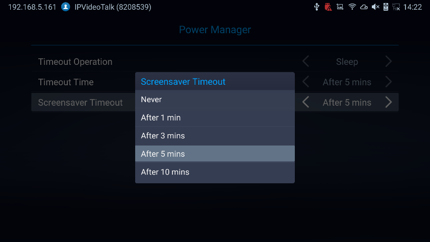
Power Manager
Timeout Operation: Choose either to put the GVC3220 in Sleep Mode or to shut it down.
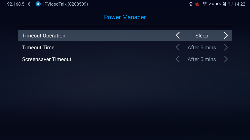
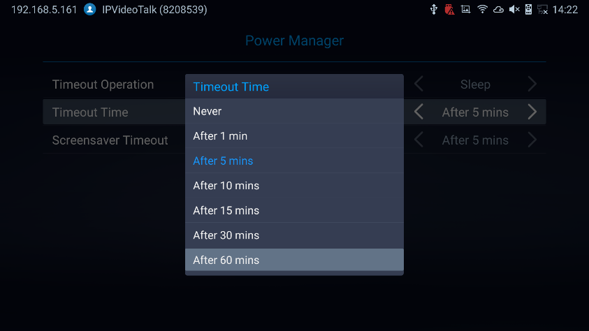
Timeout Time: Select the interval before the device enters sleep mode or shutdown. The available intervals are 1 minute, 5 minutes, 10 minutes, 15 minutes, 30 minutes and 60 minutes. The default setting is “Never”.
Screensaver Timeout: Set the screensaver timeout for the GVC to enter screensaver mode. The default value is 5 minutes. Options are: Never, after 1, 3, 5 or 10 minutes.
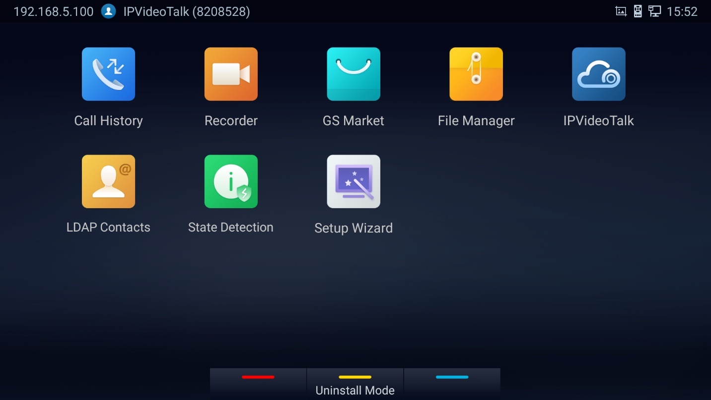
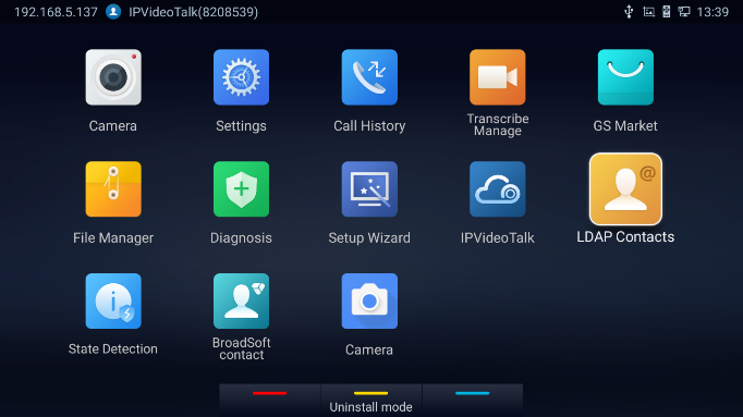
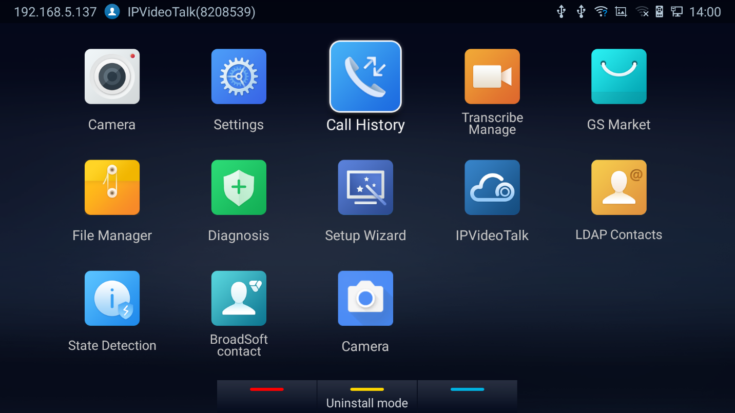
APPLICATIONS
GVC3220 provides built-in applications such as Call History, File Manager, Recorder, etc.
Users could also download the apps from GS market to install on GVC3220.
LDAP contacts
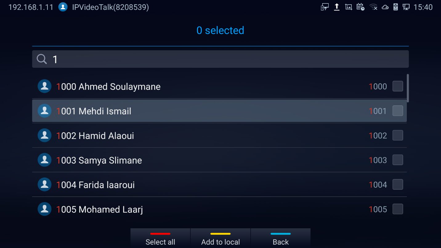
LDAP contacts application can be accessed in GVC3220 display device LCD🡺 Applications 🡺 LDAP Contacts. It helps users to access and manage the contacts at ease.
Here is the main interface of LDAP contacts:
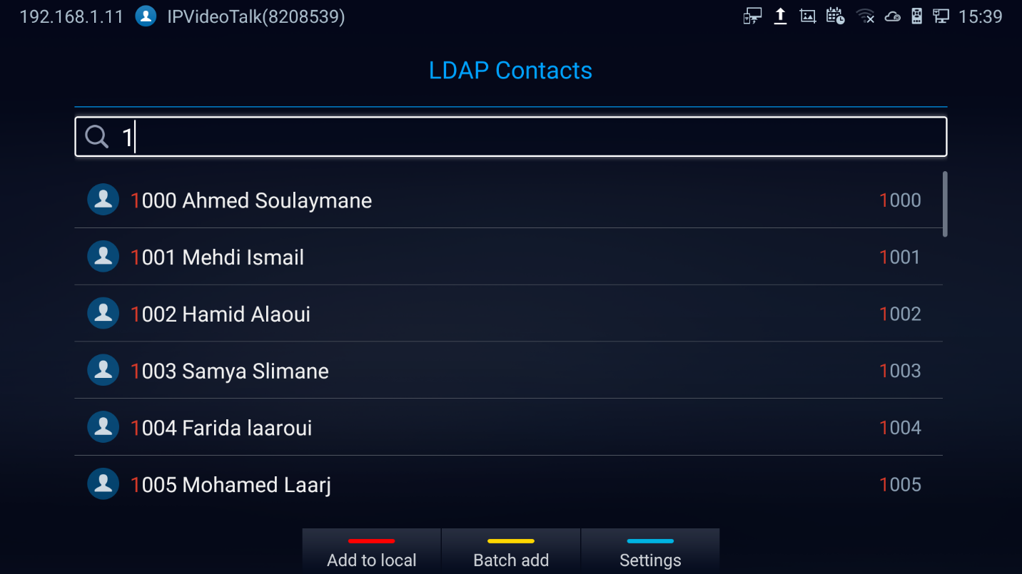
-
Press
 to Add the selected LDAP contact to the local phonebook
-
Press
 for Batch Add, the below screen will show up:
 to Add the selected LDAP contact to the local phonebook
 for Batch Add, the below screen will show up:
-
Press
 for LDAP parameters:
 for LDAP parameters:
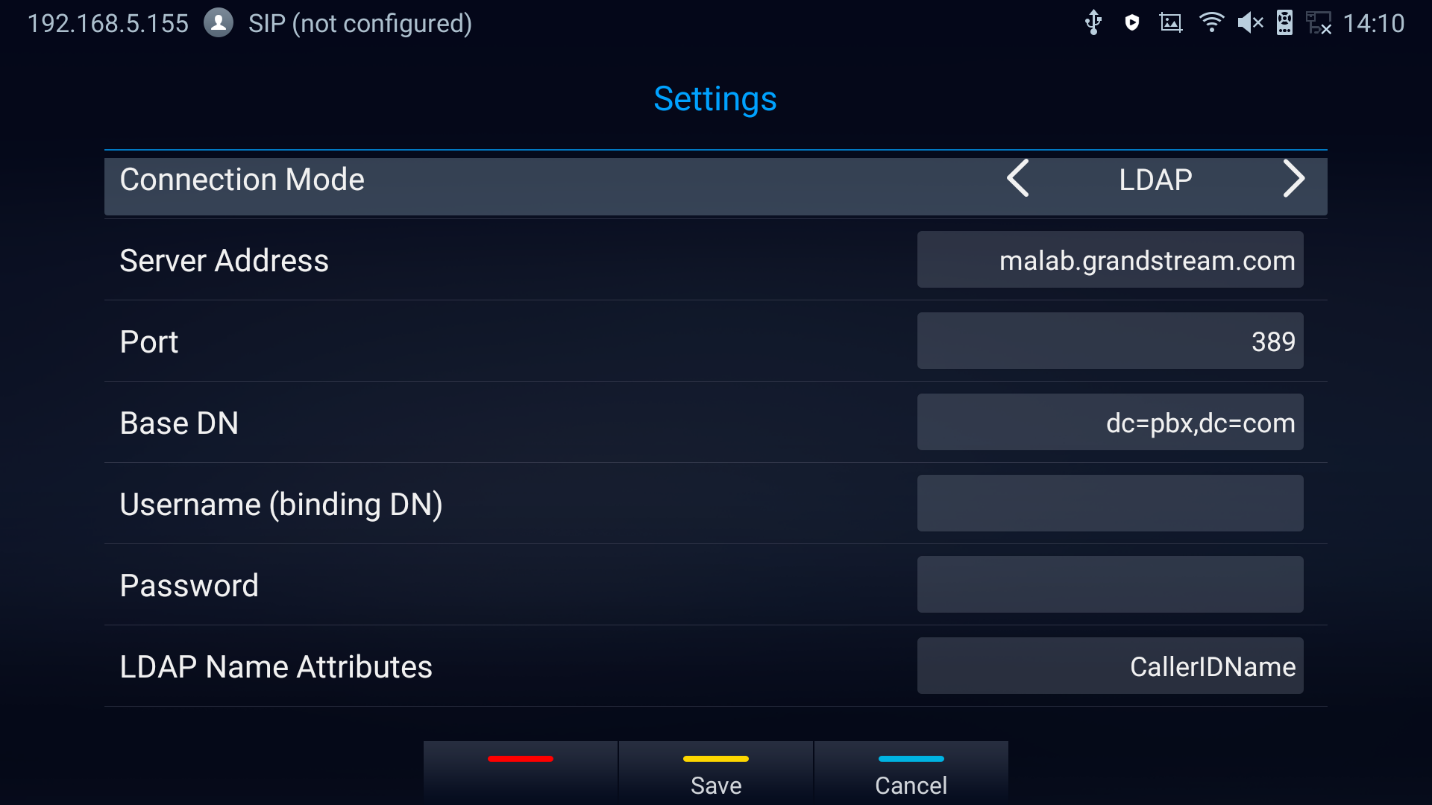
LDAP Settings
Before starting using LDAP on GVC3220, the users must configure the LDAP settings first. Press  shortcut key on the GVC3220 remote control to access LDAP settings, or the users can configure it under GVC3220 Web UI 🡺 App 🡺 LDAP page.
Connection Mode | It is used to select which protocol will be used for LDAP searching, LDAP or LDAPS. |
Server Address | It is used to configure the URI of the LDAP (Lightweight Directory Access Protocol) server. |
Port | It is used to configure the LDAP server port. The default LDAP port number is 389. |
Base DN | It is used to configure the LDAP search base. This is the location in the directory where the search is requested to begin. Example: dc=grandstream, dc=com ou=Boston, dc=grandstream, dc=com |
Username | It is used to configure the bind “Username” for querying LDAP servers. Some LDAP servers allow anonymous binds in which case the setting can be left blank. |
Password | It is used to configure the bind “Password” for querying LDAP servers. The field can be left blank if the LDAP server allows anonymous binds. |
LDAP Name Attributes | It is used to configure the “name” attributes of each record which are returned in the LDAP search result. This field allows the users to configure multiple space separated name attributes. Example: gn cn sn description |
LDAP Number Attributes | It is used to configure the “number” attributes of each record which are returned in the LDAP search result. This field allows the users to configure multiple space separated number attributes. Example: telephoneNumber telephoneNumber Mobile |
LDAP Mail Attributes | It is used to configure the “mail” attributes of each record which are returned in the LDAP search result. Example: |
LDAP Name Filter | It is used to configure the filter used for name lookups. Examples: (|(cn=%)(sn=%)) returns all records which has the “cn” or “sn” field starting with the entered prefix; (!(sn=%)) returns all the records which do not have the “sn” field starting with the entered prefix; (&(cn=%) (telephoneNumber=*)) returns all the records with the “cn” field starting with the entered prefix and “telephoneNumber” field set. |
LDAP Number Filter | It is used to configure the filter used for number lookups. Examples: (|(telephoneNumber=%)(Mobile=%) returns all records which has the “telephoneNumber” or “Mobile” field starting with the entered prefix; (&(telephoneNumber=%) (cn=*)) returns all the records with the “telephoneNumber” field starting with the entered prefix and “cn” field set. |
LDAP Mail Filter | It is used to configure the filter used for mail lookups. Example: (mail=%) |
LDAP Displaying Name Attributes | It is used to configure the entry information to be shown on phone’s LCD. Up to 3 fields can be displayed. Example: %cn %sn %telephoneNumber |
Max Hits | It is used to configure the maximum number of results to be returned by the LDAP server. If set to 0, server will return all search results. The default setting is 50. |
Search Timeout (ms) | It is used to configure the interval (in milliseconds) for the server to process the request and client waits for server to return. The default setting is 30. |
LDAP Lookup When Dialing | It is used to set if allow the phone system to do the LDAP number searching when making outgoing calls. The default setting is “No”. |
Search LDAP For Incoming Call | It is used to set if allow the phone system to do LDAP number searching for incoming calls. The default setting is “No”. |
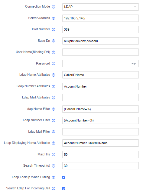
Here is an example configuration on GVC3220 LDAP settings in web UI. The LDAP server is the built-in LDAP server in Grandstream UCM6xxx:
Call History
Call History provides users access to phone’s recent call records. Users can view all records, or select different categories for incoming calls, outgoing calls, missed call and conference.
To access Call History,
- go to Home screen🡺 Applications 🡺 Call History
2. Click on a record in the call history and press to dial out this number directly. Press “OK” key on GVC3220 remote control to view call details for this number.
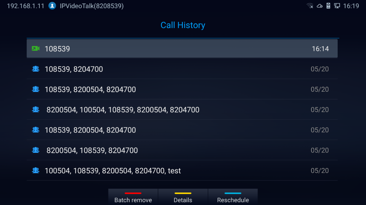
3. Users can choose to “Batch remove” history logs, show the log “Details” or “Reschedule” the call/conference
Add Contact from Call History
- Access Call History screen and Press the yellow shortcut key to bring up the details screen.
- Press again the yellow shortcut to “Add” to contacts
- Select to add as new or existing contact.
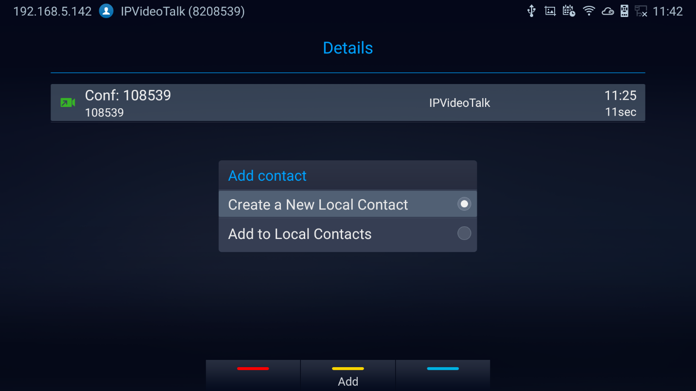
4. Select existing contact or press the blue shortcut key on GVC3220 remote control to access edit screen.
5. Fill in contact information and press the yellow shortcut key on the remote control to save the contact.
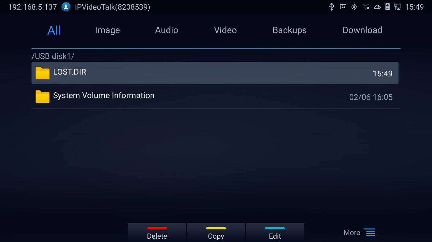
File Manager
File Manager allows users to delete, move, copy, paste, send, rename files (including files on storage device such as USB flash drive and SD card), and query file properties on GVC3220.
Browse Files
- Insert USB/SD storage device into USB port on GVC3220. It will take a few seconds for GVC3220 to prepare the connection.
- The USB storage icon will show up on the status bar.
- Go to Home screen 🡺 Applications 🡺 File Manager.

4. Open the target folder:
- All: Internal storage and Storage devices (USB or SD Card)
- Image: image files and screenshot
- Audio: audio files only
- Video: video files only
- Backups: Saved backups
- Downloads: Saved download files
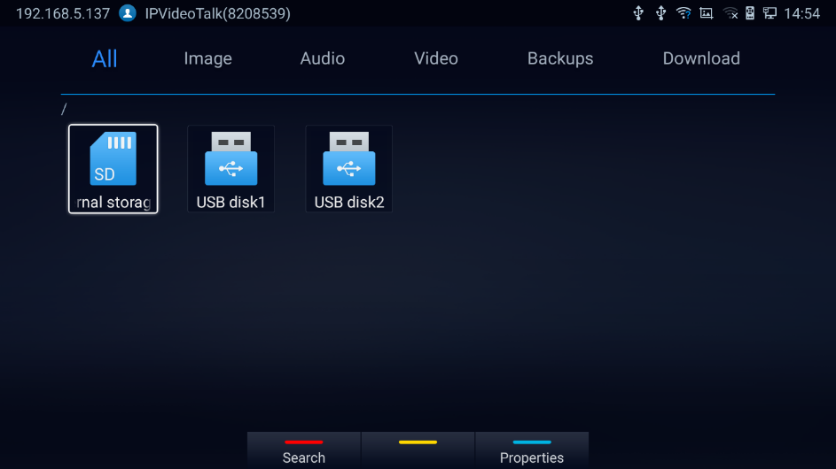
5. Press  shortcut key to search for a file.
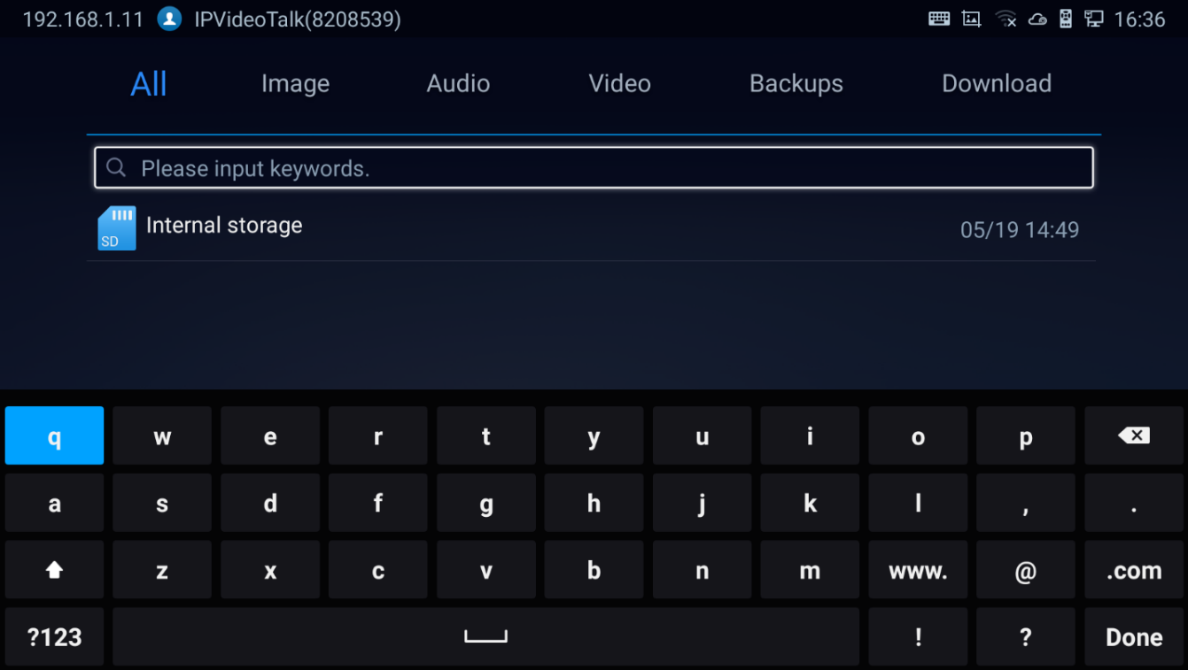
6. Press  shortcut key for properties
File Operations
- Go to Home screen 🡺 Applications 🡺 File Manager.
- Open the target folder and select the file.
- Possible File operations are available on the bottom panel
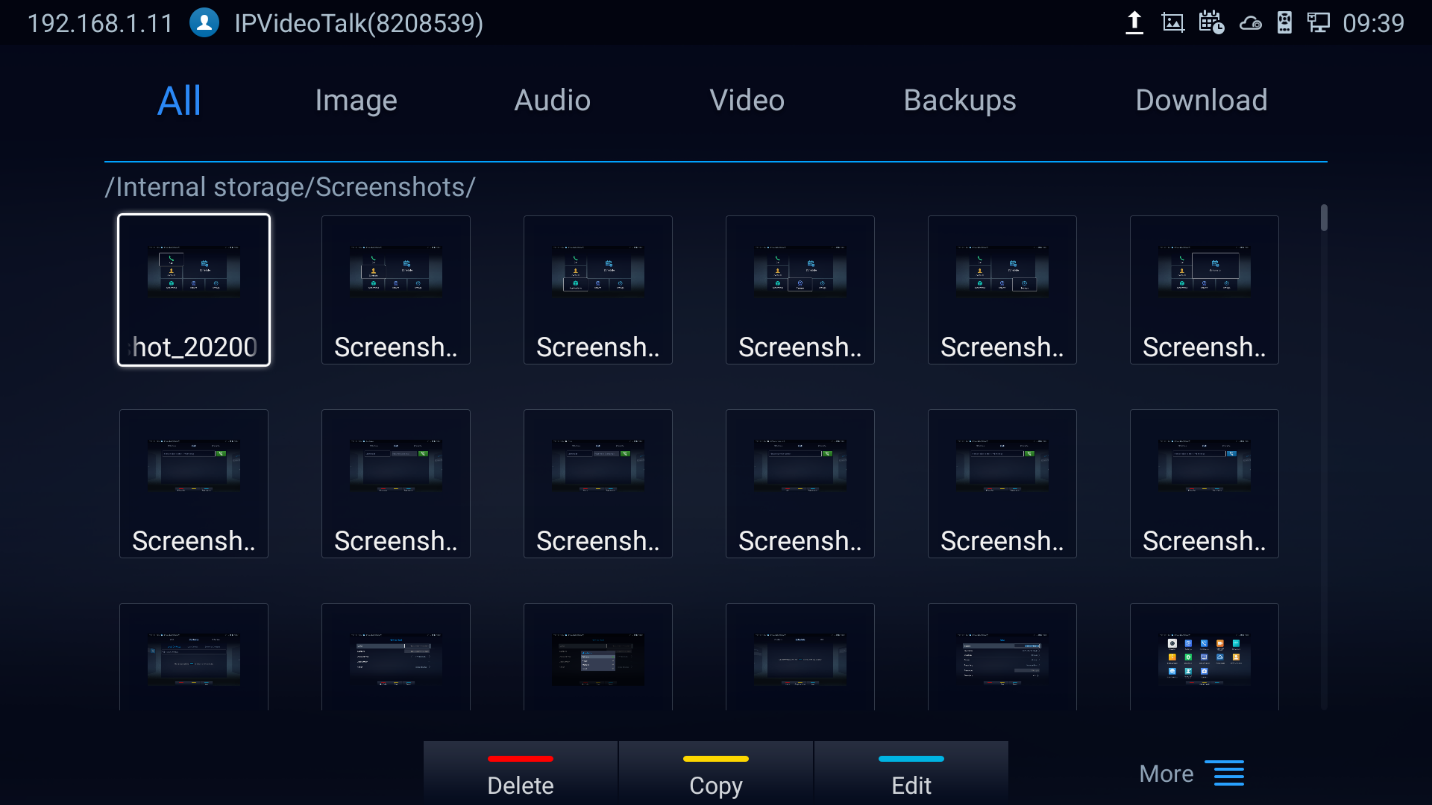
- Press the red shortcut key to “Delete” the selected file
- Press the yellow shortcut key to “Copy” the selected file
- Press the blue shortcut key to “Edit” the selected file, it provides “Select all” option to batch Delete/Copy files.
-
Press
 to show the operation panel :
-
Click
 “Back” to bring the previous screen
-
Click
 to send the file via Bluetooth or other 3rd party applications such as MS Teams:
-
Click
 to show the operation panel :
 “Back” to bring the previous screen

-
Click
 to “Rename” the file:
 to “Rename” the file:
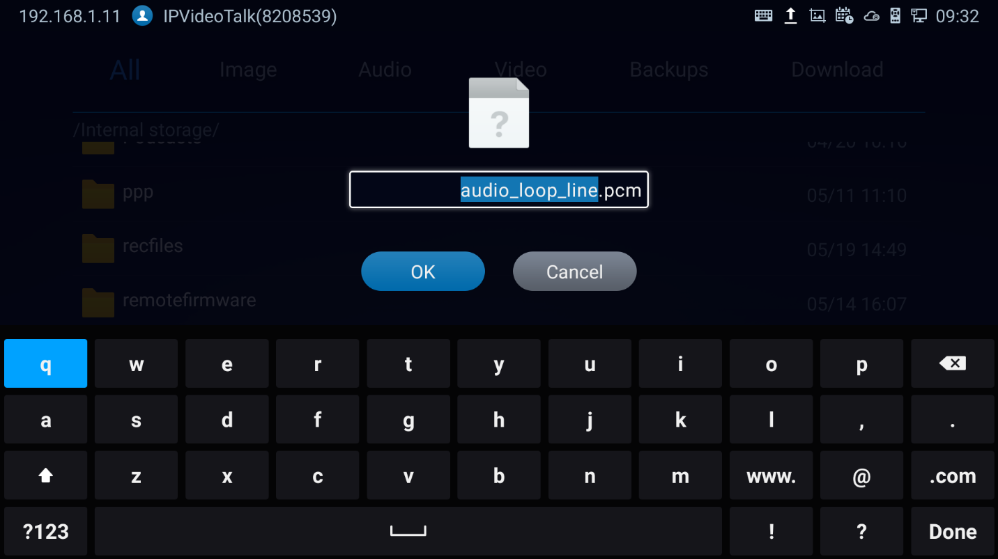
-
Click
 to show the file “Properties:
 to show the file “Properties:
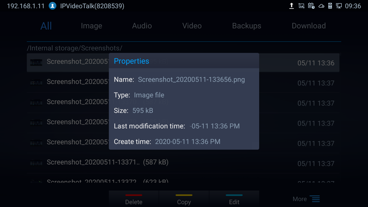
-
Click
 to search file:
 to search file:
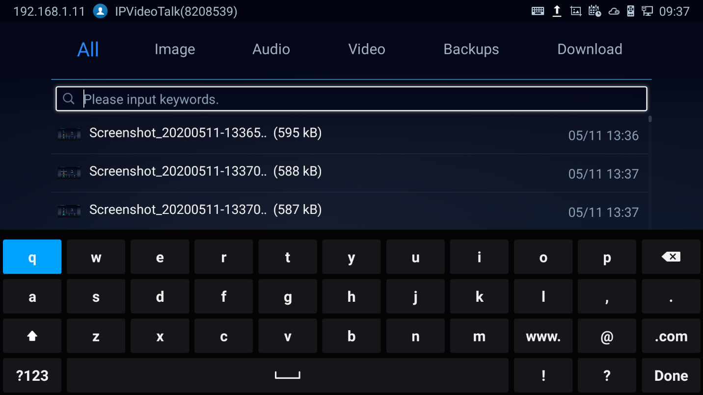
-
Click
 to create a new folder: A popup will appear to name the new folder
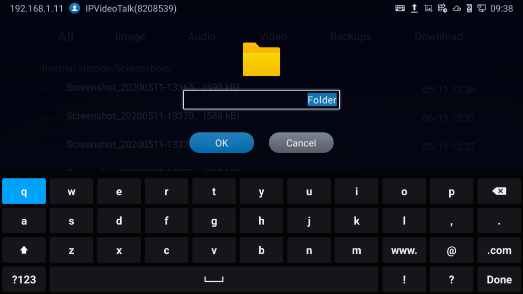
-
Click
 to sort files: A popup will appear to allow choosing the Sort option
 to sort files: A popup will appear to allow choosing the Sort option
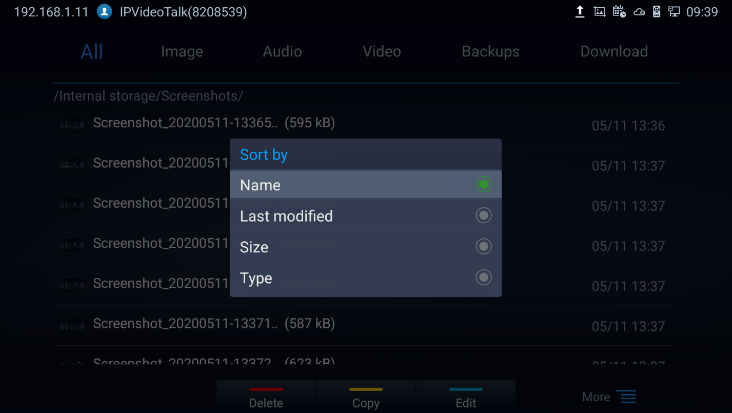
-
Click
 to change the display mode between icon or list.
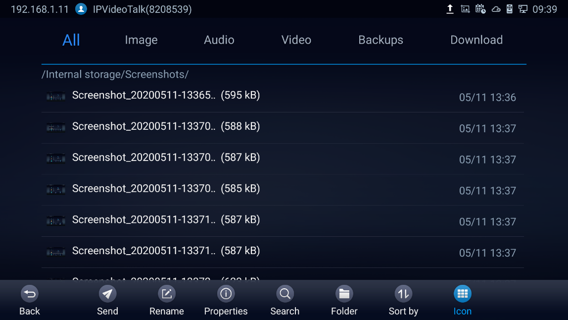
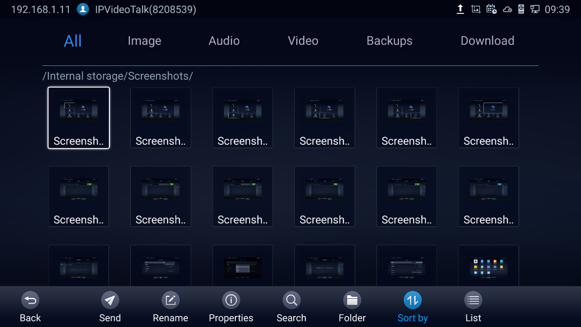
Recorder
The GVC3220 Recorder Application is used for the storage of call recording files for both video and audio conferencing. Users can play, export, lock/unlock, send, rename, or delete these recordings and etc.

The recording screen is as shown below:
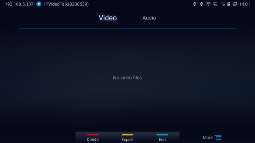
Notes:
- Recording files can be saved to an external SD card, USB flash drive, FTP server or NAS extended storage.
- The locked files cannot be deleted or overwritten, and cannot be shown in the third-party application, but can be viewed in GVC3220 Recorder application.
- When the recording size exceeds 1.9G, the GVC3220 will create a new file automatically to continue recording. There will be a prompt to indicate the storage space is insufficient if the disk storage is full.
- Users can access Video Settings by clicking
 🡺
🡺  :
:
 :
: 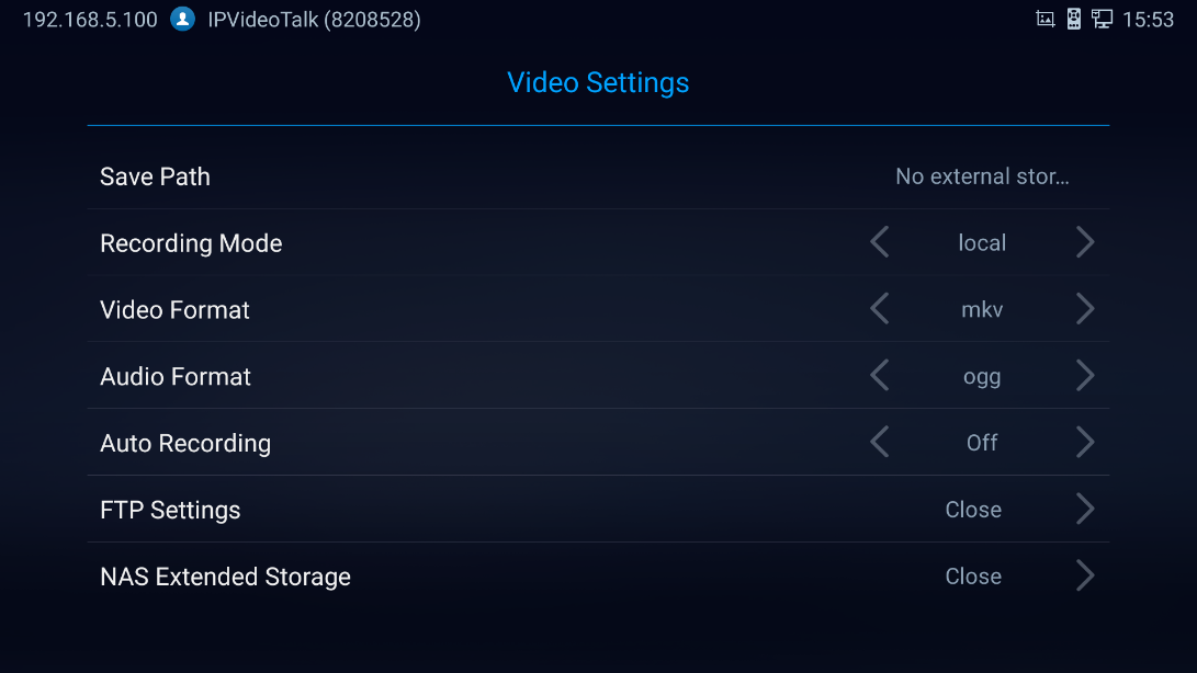
Setup Wizard
GVC3220 offers a Setup Wizard tool to guide users into configuring their units step by step, the setup wizard appears automatically at factory reset, or it can be accessed anytime from LCD menu 🡺 Applications 🡺 Setup Wizard.

Users can follow the steps using the remote control to setup fields, skip, return, or confirm the action.
Setup wizard tool is useful to lead users to check and configure the GVC3220 settings such as language, accounts, interface status and etc.
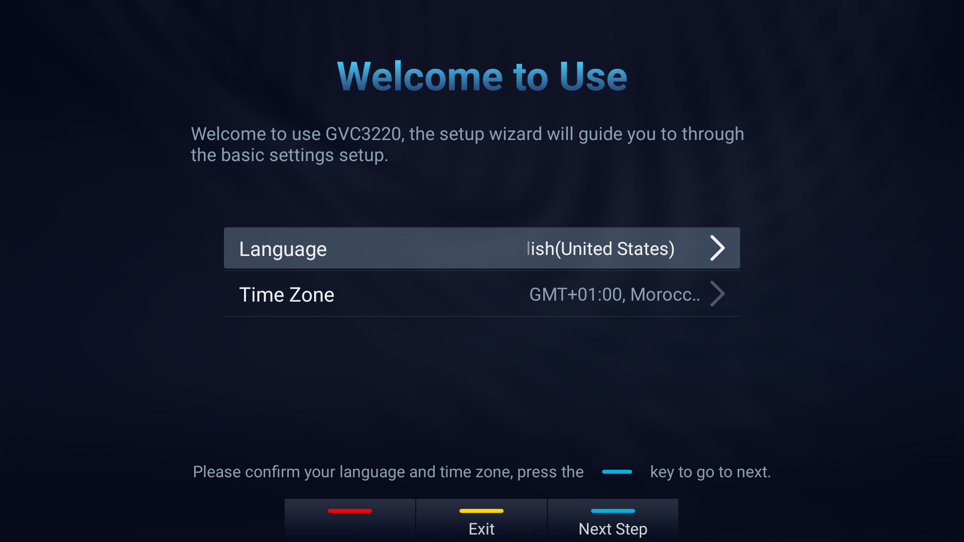
- Choose Language and Time Zone Then, click
 to proceed.
 - The following step is “Remote Control Pairing”:
- Follow the displayed steps to properly pair your remote-control device
- Configuration Mode: Users can choose to either complete the configuration through the wizard or through the mobile App.
 to proceed.
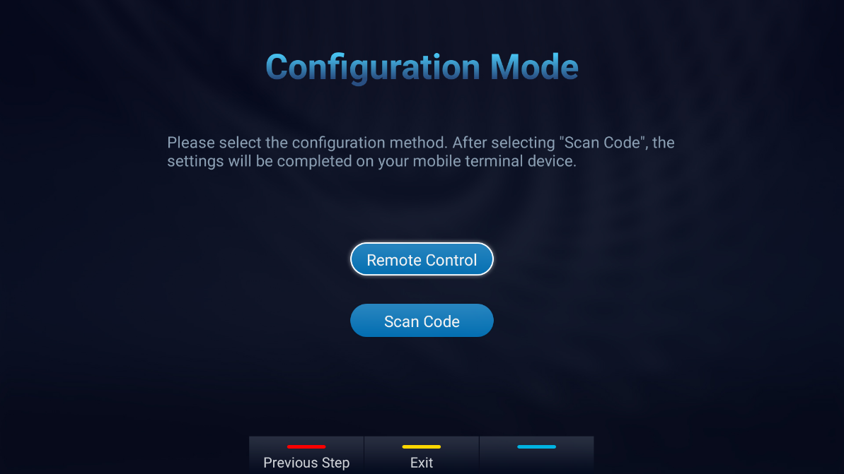
- After pressing
 the GVC3220 Setup Wizard will initiate.
 the GVC3220 Setup Wizard will initiate.
 - Detect active GVC3220 ports:
- This allows users to make sure that all the connected interfaces are working properly.
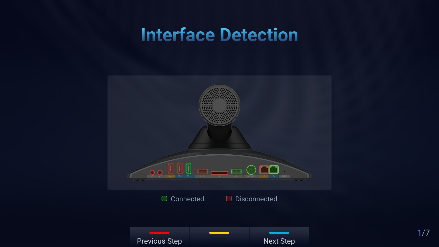
2. Network Configuration:
- Ethernet: Set DHCP or a Static IP
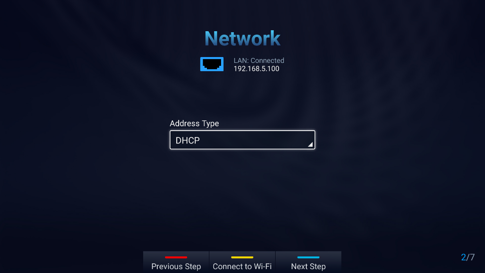
- Fill in the Static IP parameters:
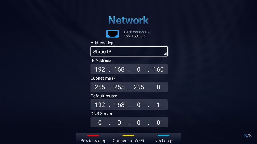
- Press the Yellow shortcut key to connect a Wi-Fi Network:
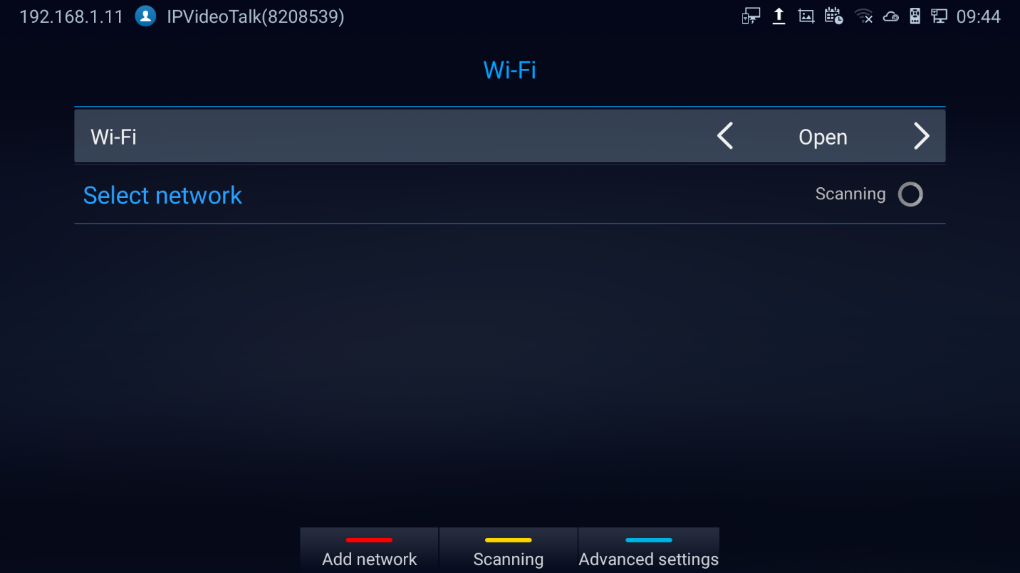
3. Launch GMD wireless microphone paring process:
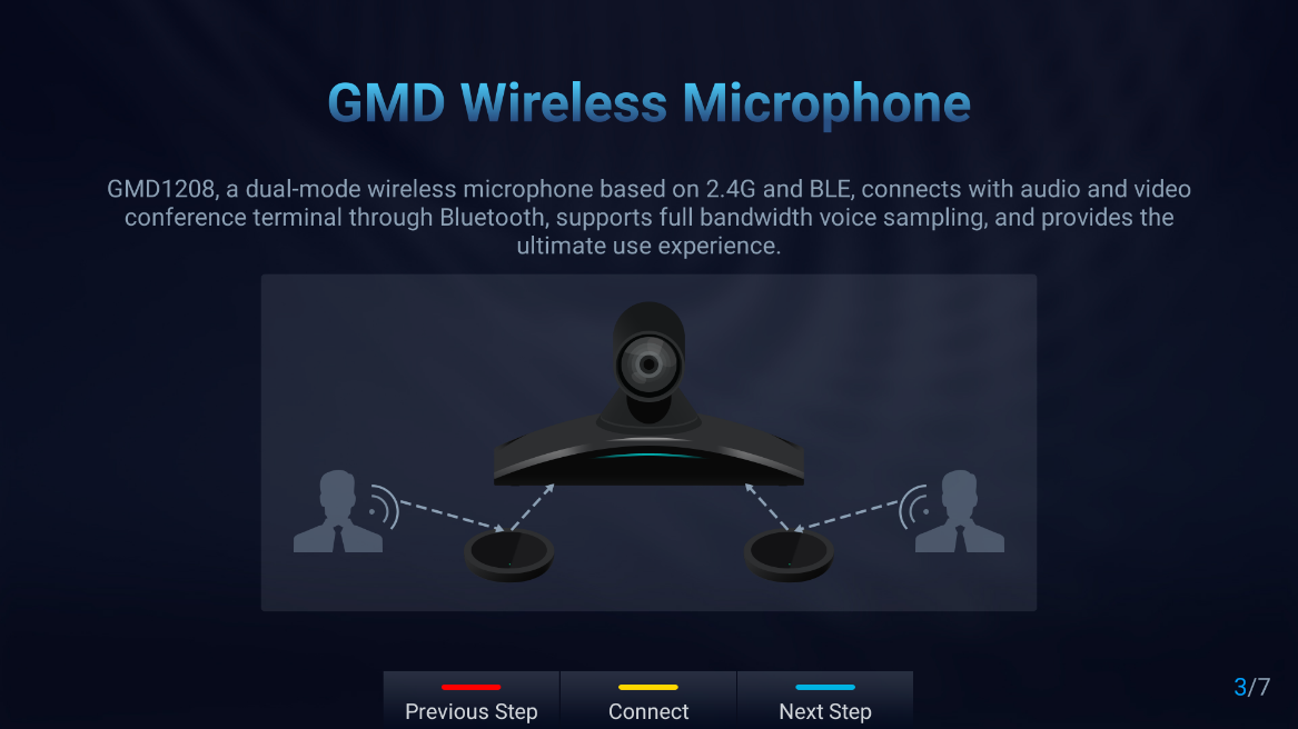
4. SIP Account configuration:
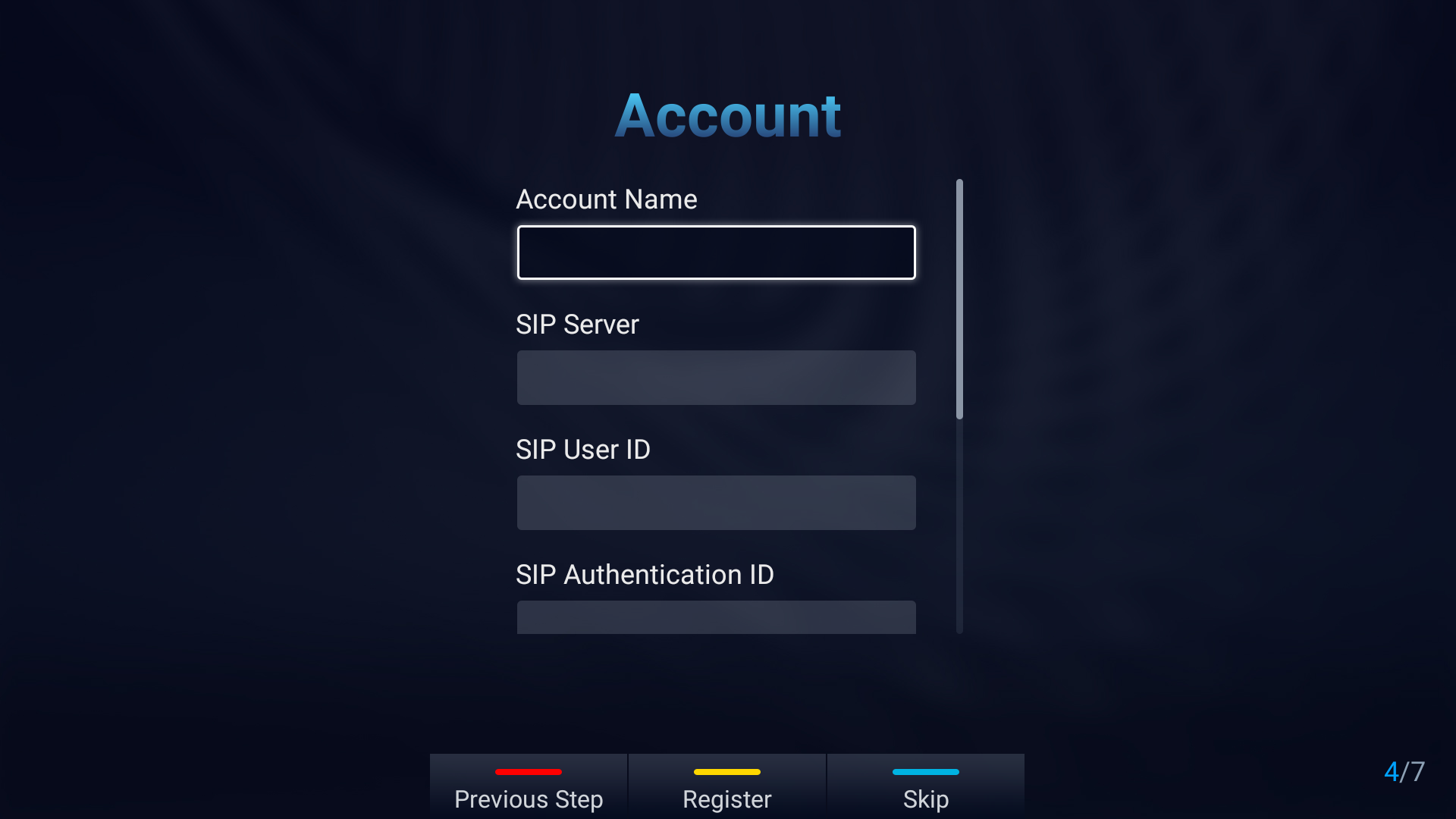
5. Remote Control Description:
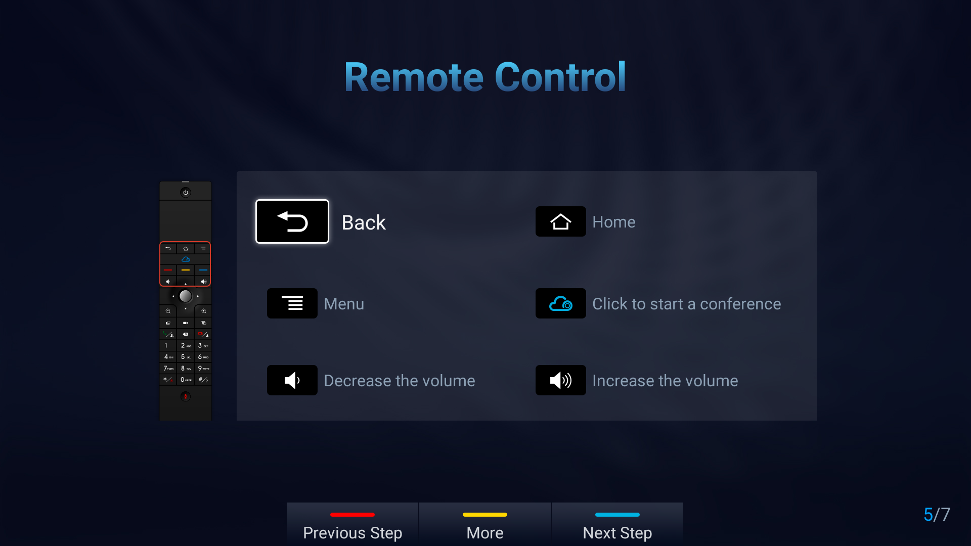
- Click “More” for advanced options: Users can check the hardware/software version, upgrade firmware or download “GVC Remote” apk …
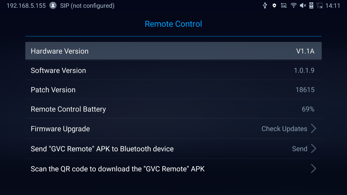
6. Introduction to IPVideoTalk Service:
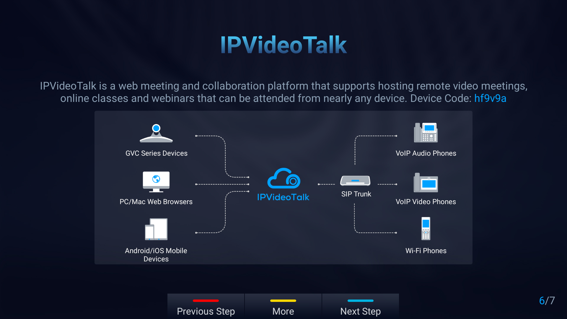
7. Completing the Setup Wizard:
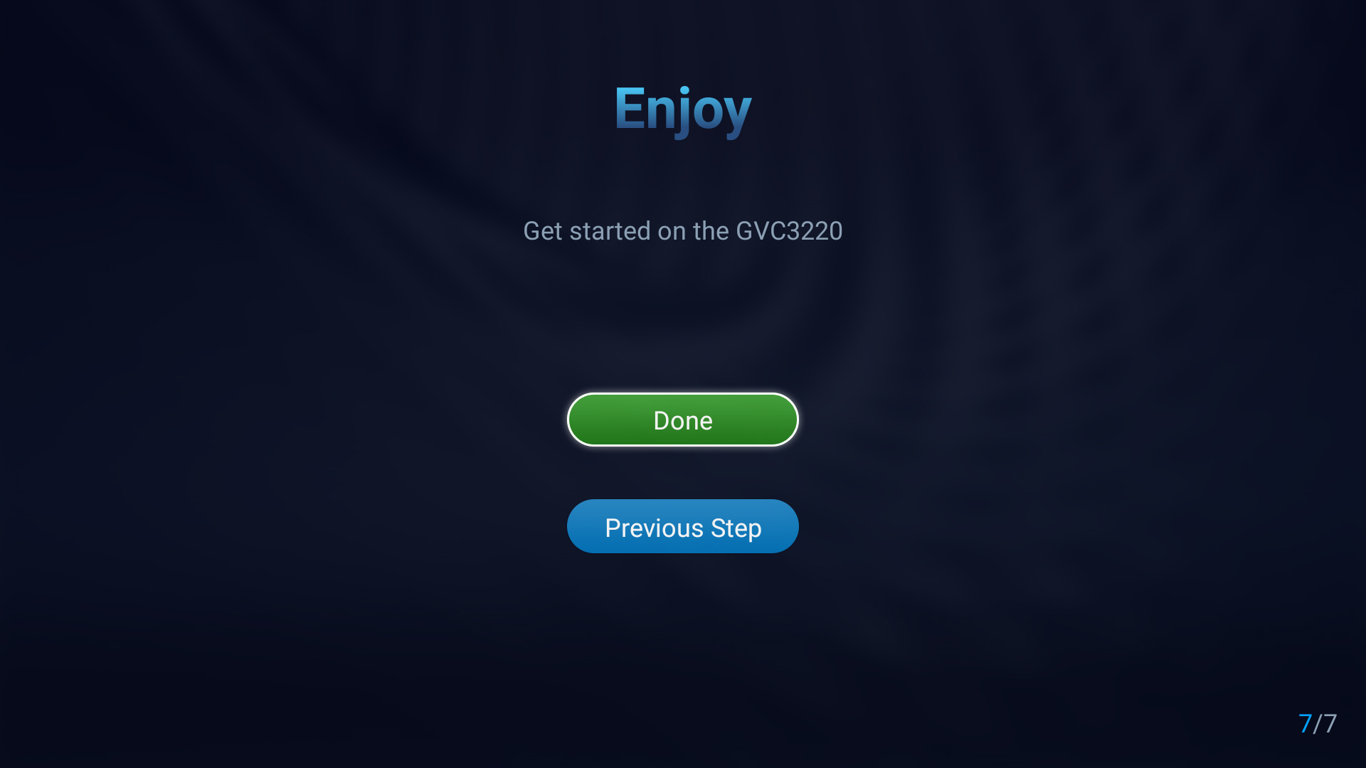
- Click “Done” to finish the Setup Wizard and start using the GVC3220.
Backup
Backup Data
GVC3220 BACKUP application is used to back up data or import backup files to restore data. It can be accessed from Home screen 🡺 Applications 🡺 File Manager 🡪 Backups
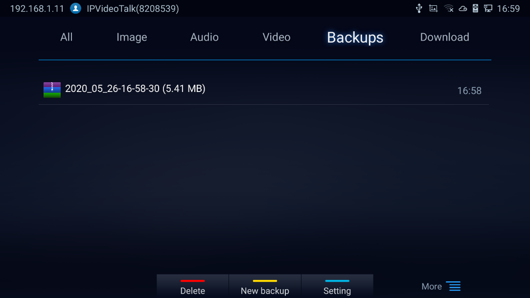
GVC3220 supports manual backup and automatic backup:
- Press the yellow shortcut key on the remote control to create new backup manually. The user will select preferred backup data and press the yellow shortcut key again to start backup.
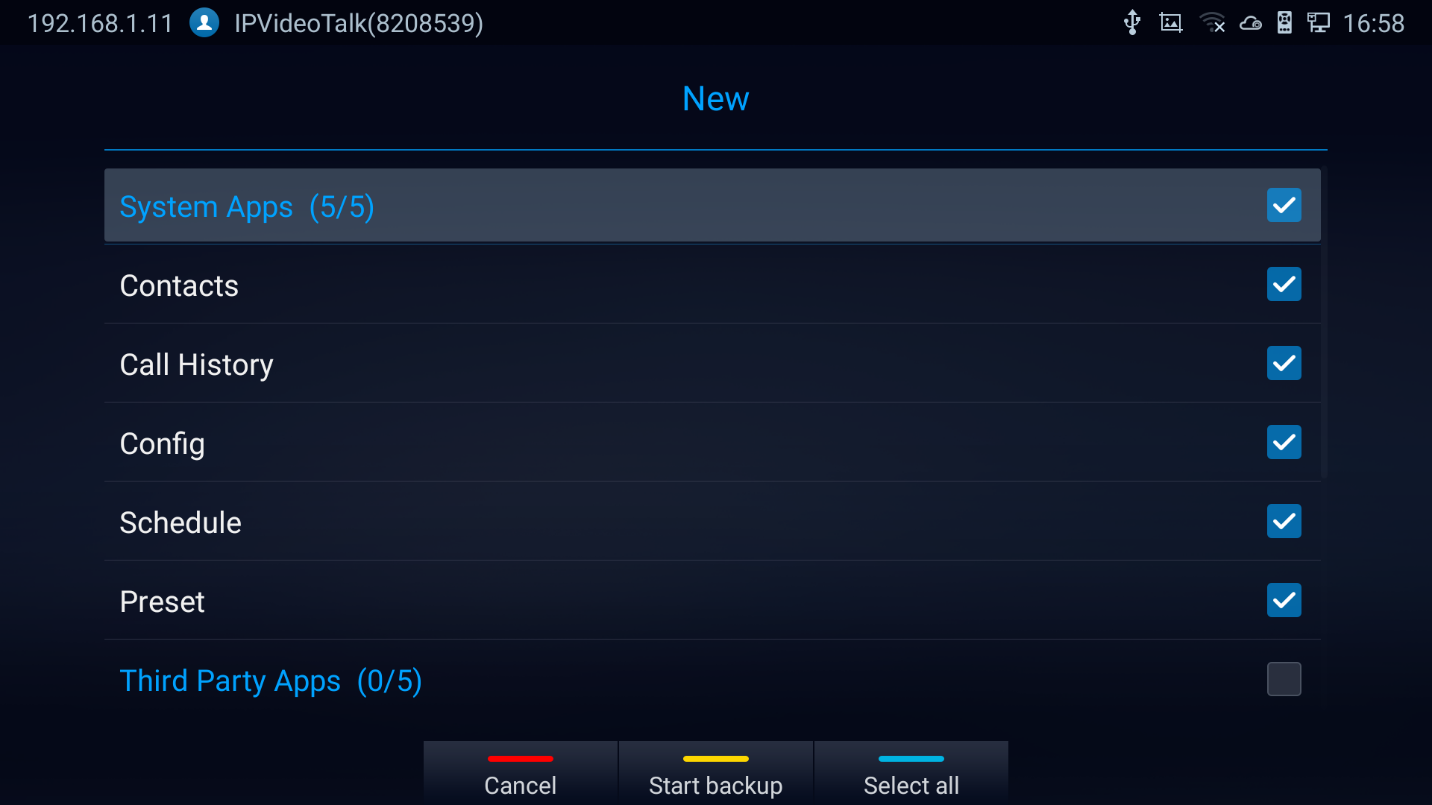
- Press the blue shortcut key on the remote control to enable and configure automatic backup Settings:
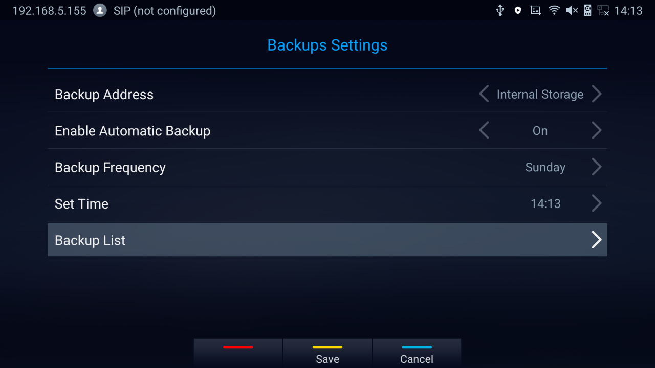
Restore Backup Data
Select one backup data and press “OK” key to access restore screen, select the preferred data, and press the yellow shortcut key to start the restore process:
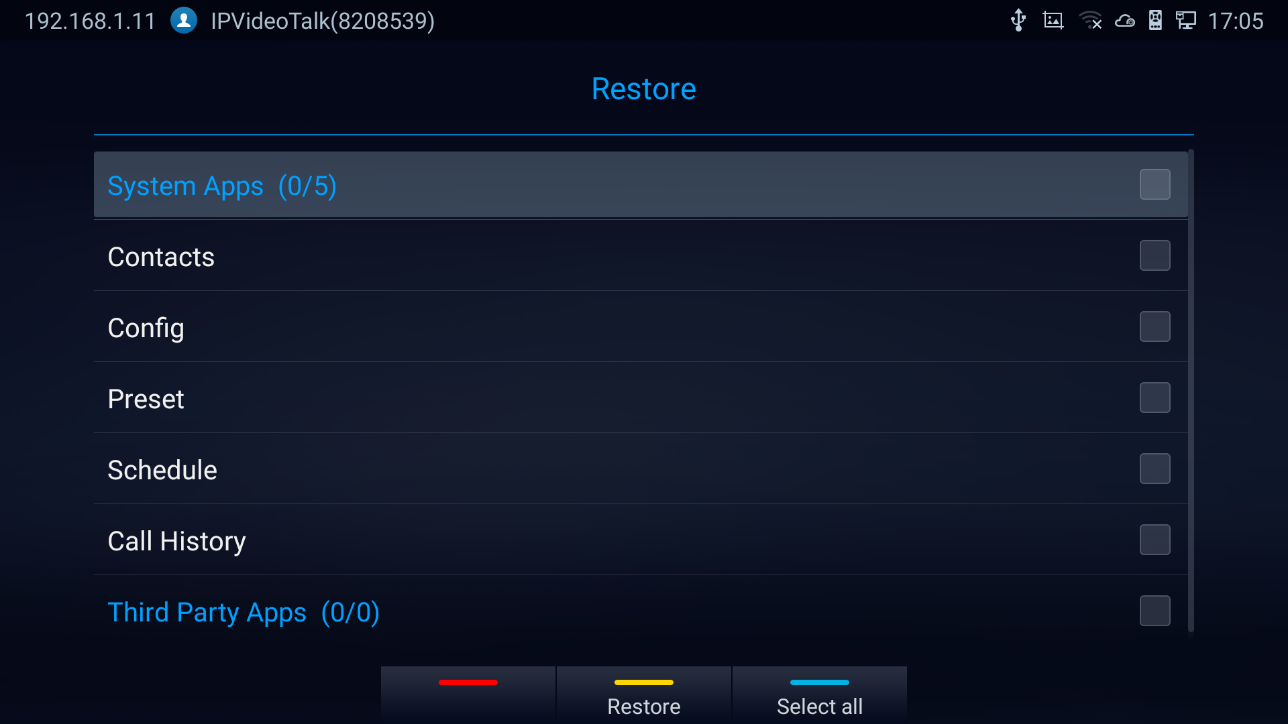
State Detection
When troubleshooting GVC3220, users could go to GVC3220 home screen 🡺 Applications 🡺 State Detection
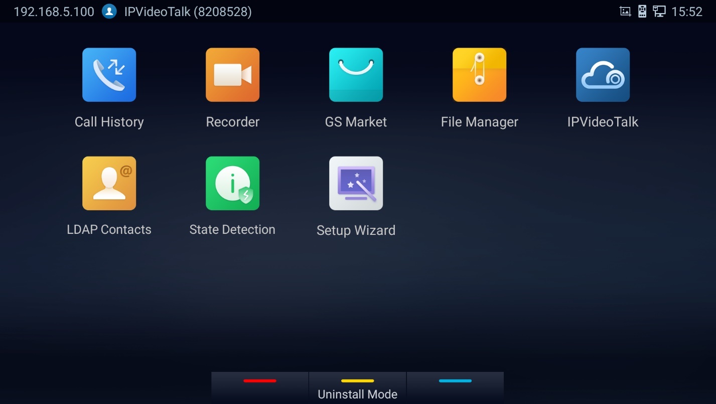
Then, users can have access to the below information:
- Interface Detection: To verify that all the connected interfaces are working properly.
- Network Detection: To make sure that the active Network Interfaces are connected
- Account Detection: To double check the account registration status
- Audio Detection: Users can perform an Audio loopback test to verify if the Audio Output device is working fine. (Follow the displayed instructions to record audio input then play it back)
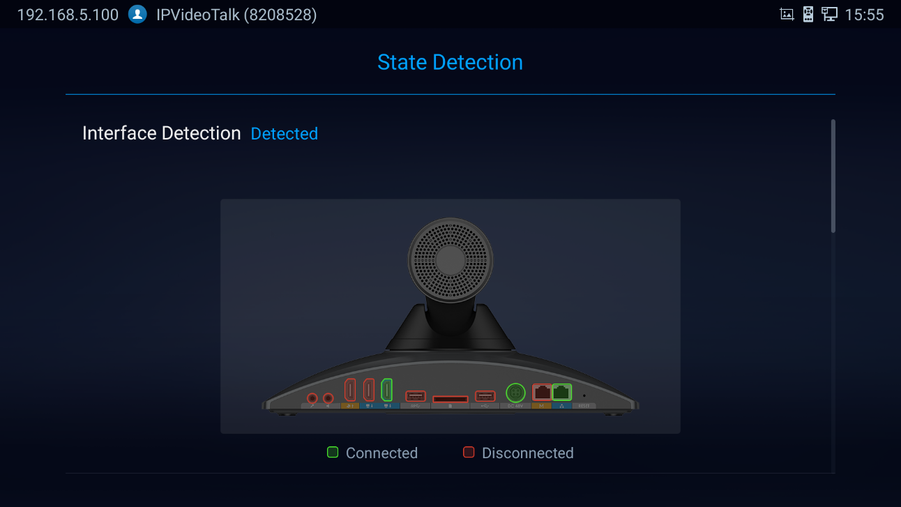
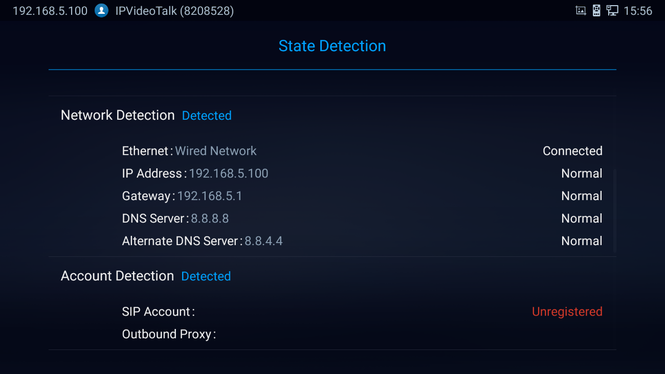
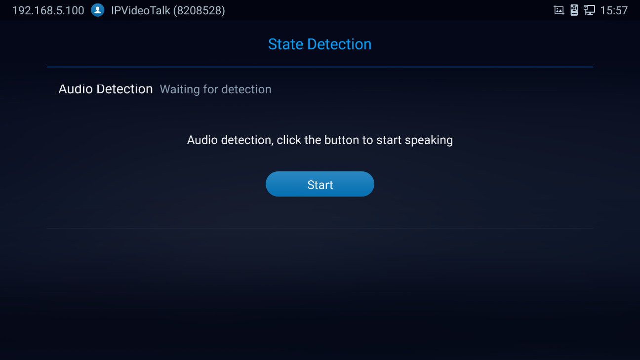
The apps that are not built-in on GVC3220 can be moved to an external SD card plugged to the GVC3220 from GVC3220 LCD 🡺 Settings 🡺 System 🡺 Apps page.
- Users could check the apps list on the external SD card by pressing OK on the Remote Control:
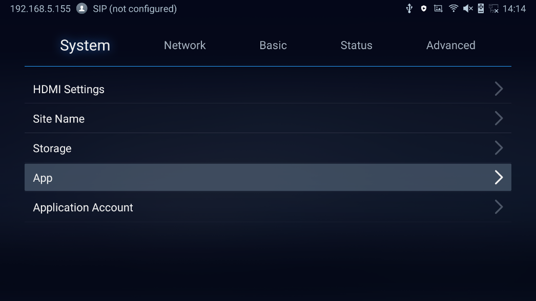
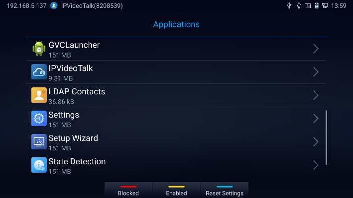
 to show Blocked Applications,
 to display the allowed Applications
 for Reset app preferences:
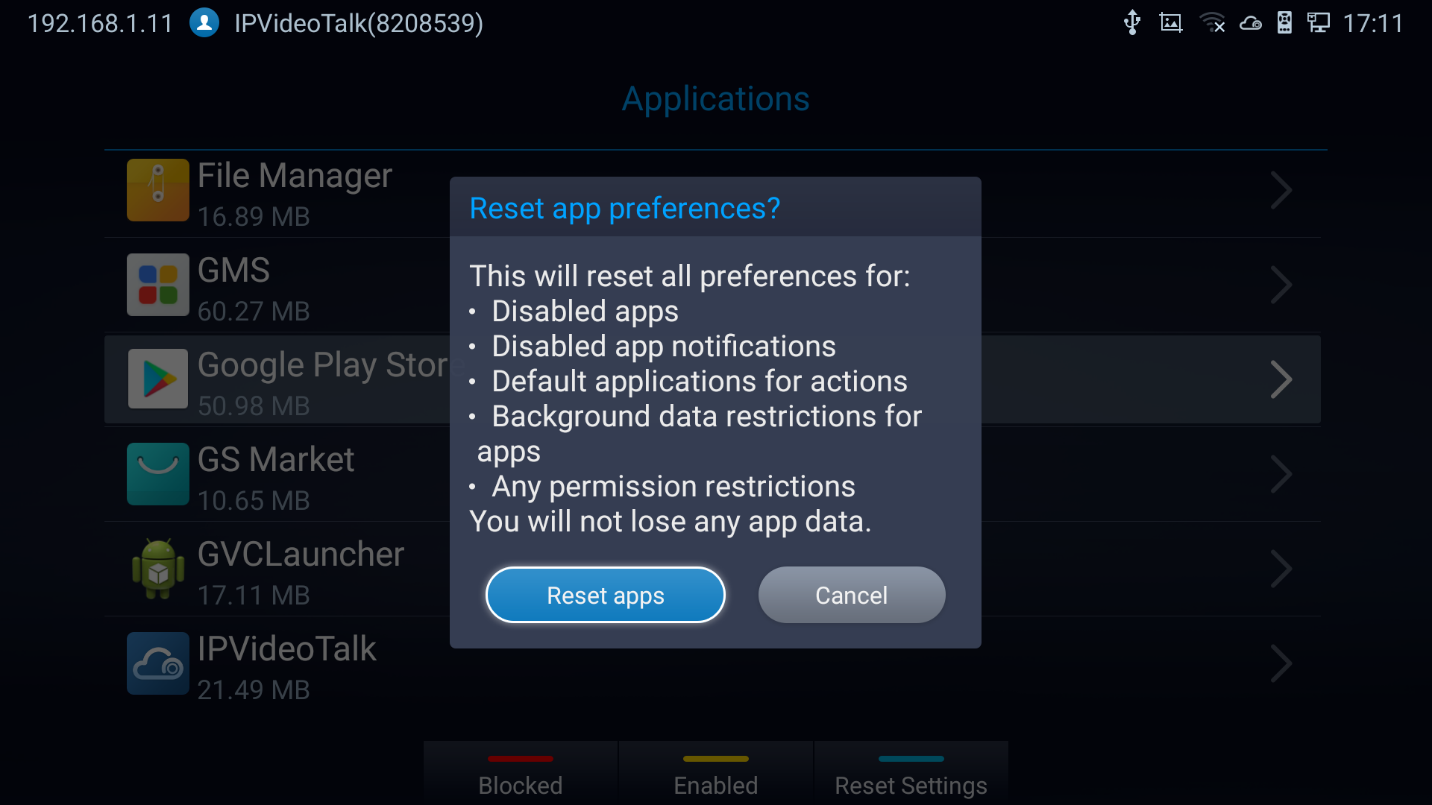
Uninstall Application
The applications (except the system applications) on GVC3220 can be uninstalled. Go to LCD Home screen 🡺 Applications, click on YELLOW shortcut key to enter the “Uninstall Mode“.
-
Users will see the apps that can be deleted shown with
 icon. Select and confirm the uninstallation:
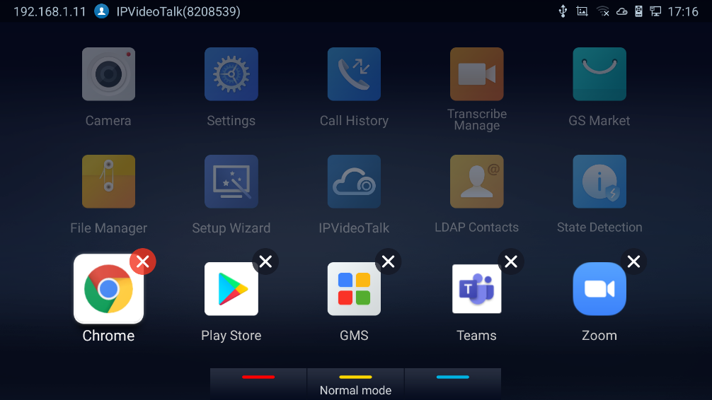
- Once done, press the yellow shortcut key on the remote control to go back to normal mode.
GS MARKET
GVC3220 provides access to apps directly via built-in GS market. Users could download the apps from the market and install to GVC3220.
View Apps
On GVC3220 Home screen, click on Applications 🡺 GS Market Users could view the apps by category:
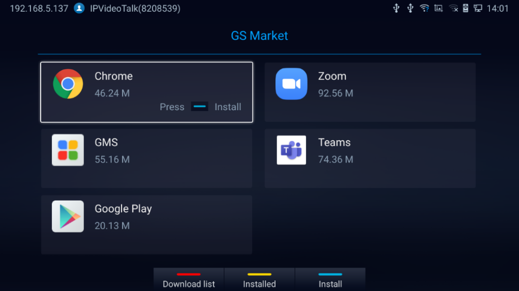
 to show the download history,
 to display available/installed APPs
 to start/stop installing the selected App.
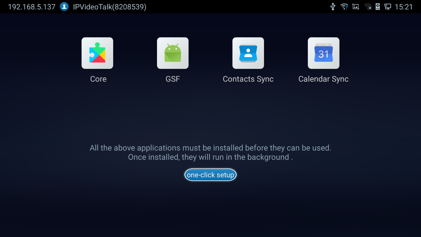
Update Apps
GVC3220 will detect to update automatically if there is new version available for the installed apps when the network connection is normal. Users can view the relevant information, and update apps on the “Installed” screen.
IPVIDEOTALK
The GVC3220 has a built-in IPVideoTalk account (active by default). The IPVideoTalk application provides an interface for the user to manage this service on the GVC3220, e.g., view enterprise directory contacts, check and reply to notices from IPVideoTalk server as well as change IPVideoTalk settings. The user can access IPVideoTalk application from LCD 🡺 Applications 🡺 IPVideoTalk.
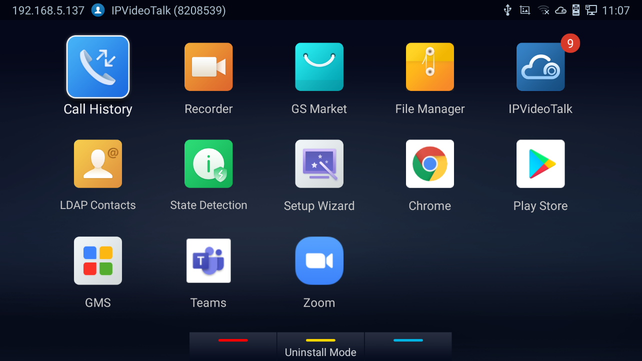
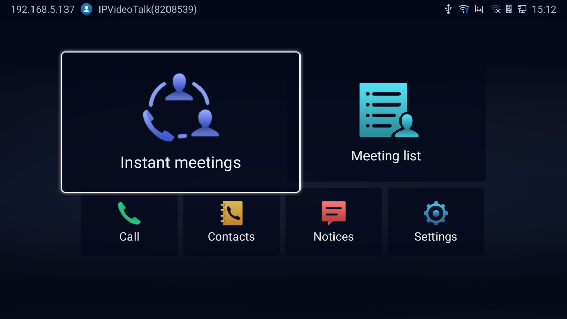
Instant Meetings
Users can start an instant meeting just by selecting
 to display IPVideoTalk Call Screen. Once it is done, the user will be the host of this instant conference and will be able to add more participants and manage everything about the conference.
Meeting List
Users can view all the scheduled meetings by selecting
 , this will take the user to the meetings list page where all the scheduled conferences are listed.
Call
Users can select
 in order to directly go to the dial page.
IPVideoTalk Contacts
The contacts are managed centrally in the server side. Users can access by selecting
 . This will show the Enterprise Contacts screen.
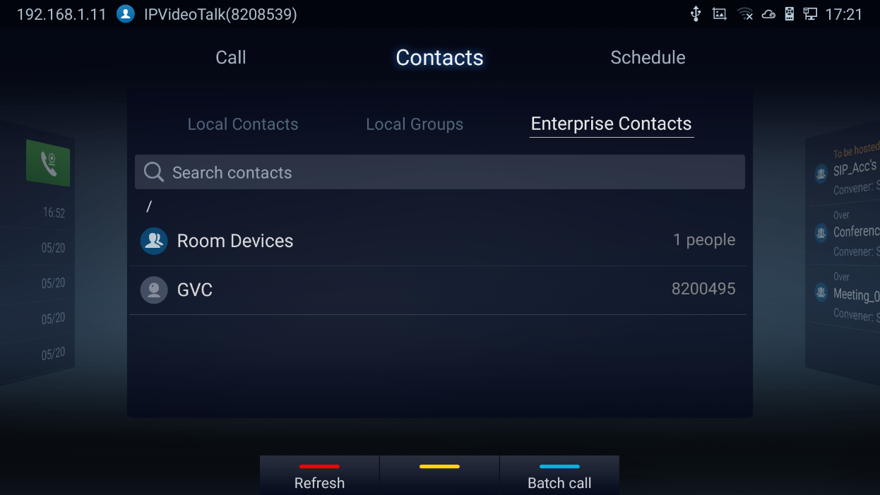
-
Select an entry in the directory and press the Green Call button
 on the GVC3220 remote control to call this contact.
- Press the red shortcut key on the GVC3220 remote control to refresh the directory.
- Press the yellow shortcut key on the GVC3220 remote control to search contacts in the directory.
- Press the blue shortcut key on the GVC3220 remote control to select entries and make a batch call to multiple contacts in the directory.
Notices
In the IPVideoTalk application, any incoming messages from the server side will be displayed in “Notices”. In the following figure, “4” indicates the number of new/unread messages.
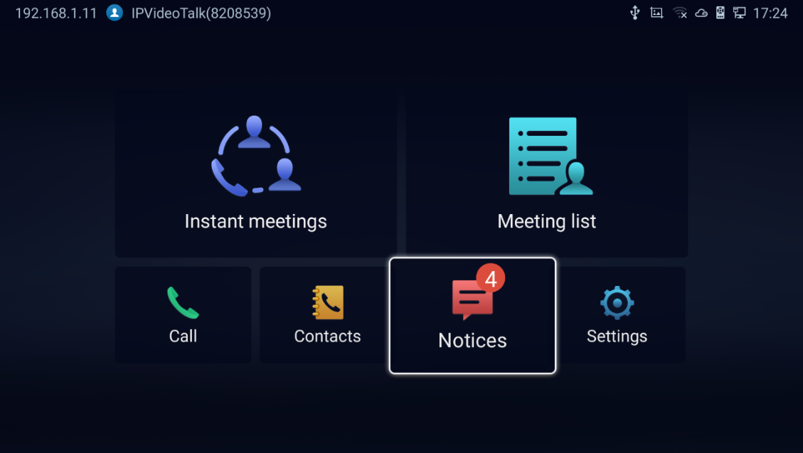
- Click on “Notices” to access the messages. Use the navigations keys/OK keys on the GVC3220 remote control to select and read the messages.
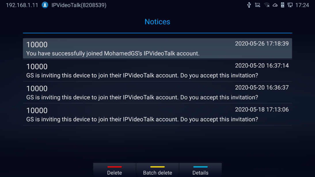
- Press the blue shortcut key on the remote control to show details:
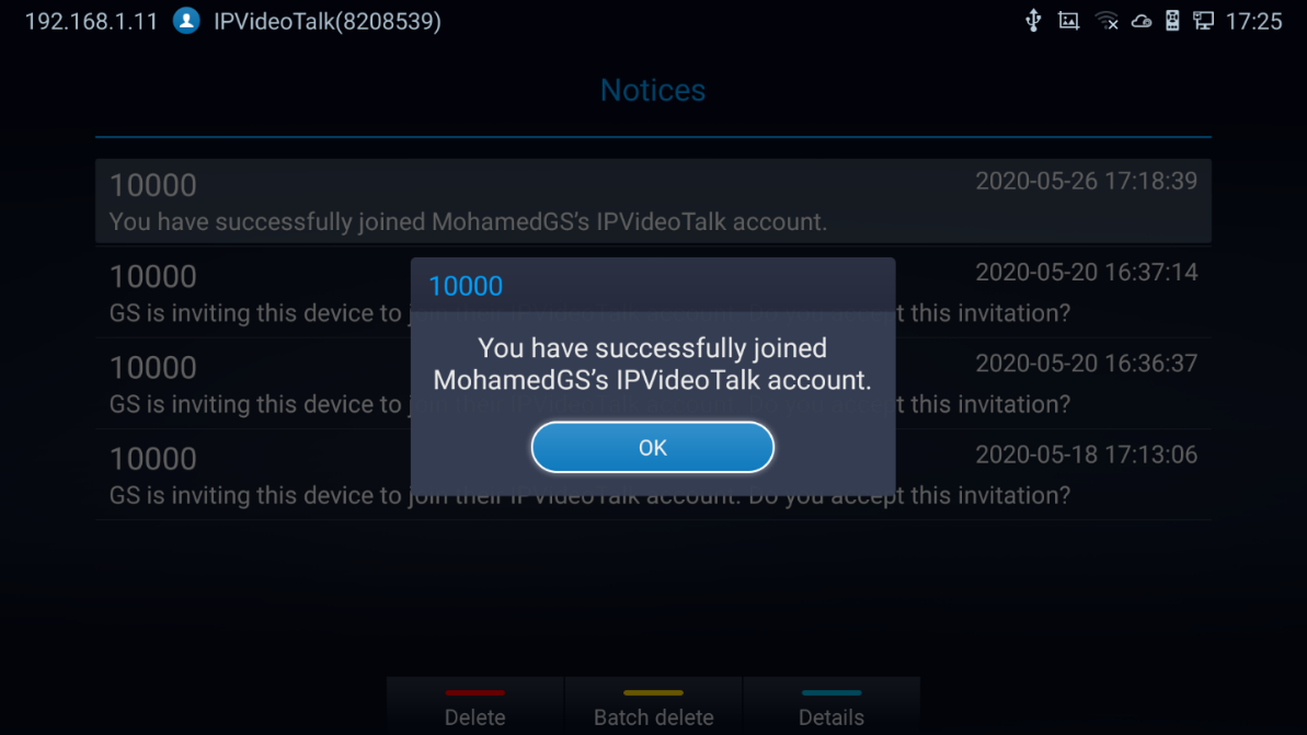
Settings
In the IPVideoTalk application, click on
 to configure “Account Active” and “Display Name” for the IPVideoTalk account on GVC3220. The user can also enter the IP address of his IPVideoTalk Server, or restore it to the default, then click on “Save” to link the GVC3220 unit with the IPVideoTalk Server configured. Current IPVideoTalk version information will be shown under “Application Information”.
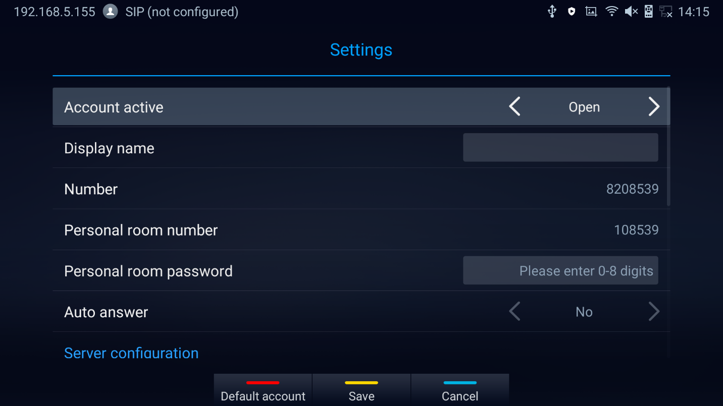
 to Cancel modification
 to keep changes
 for default account configuration.
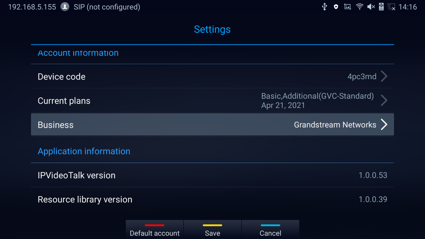
Join an IPVideoTalk Meeting
Users can join an IPVideoTalk meeting by dialing the host GVC3220’s IPVideoTalk ID or meeting ID. Please note only after meeting starts, GVC3220 can use this method to join the conference as a participant.
- Access the dialing page and Dial the meeting ID or the IPVideoTalk ID to join an active meeting.
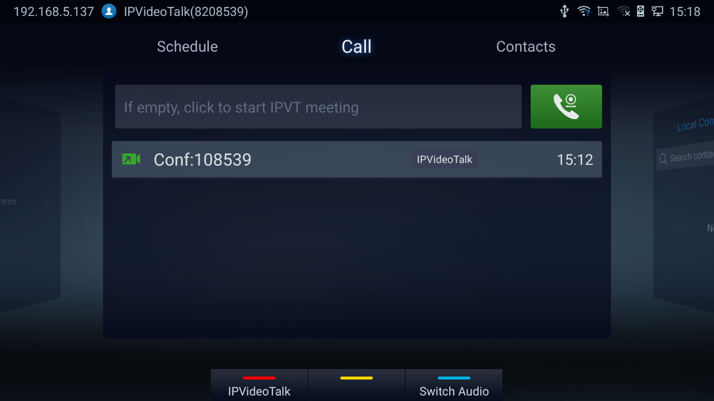
Busy Tone Responses
The GVC3220 can only join one IPVideoTalk meeting at a time. A specific busy response message will be displayed rather than SIP 486 busy error prompt on IPVideoTalk dialing interface when users try to invite a busy unit.
- If the GVC is already hosting a meeting, it cannot be added as a participant of another IPVideoTalk meeting.
- If the GVC is already a participant in an active IPVideoTalk meeting, it cannot be added to another meeting.
Manually Start IPVideoTalk Tip
If a meeting is scheduled from IPVideoTalk Web Portal, then the meeting will sync to host GVC3220 device LCD 🡺 Schedule interface. There will be a prompt message “Manually start the meeting will need to re-schedule, please confirm” when pressing “CALL” button on remote to start the meeting manually before or after scheduled time.
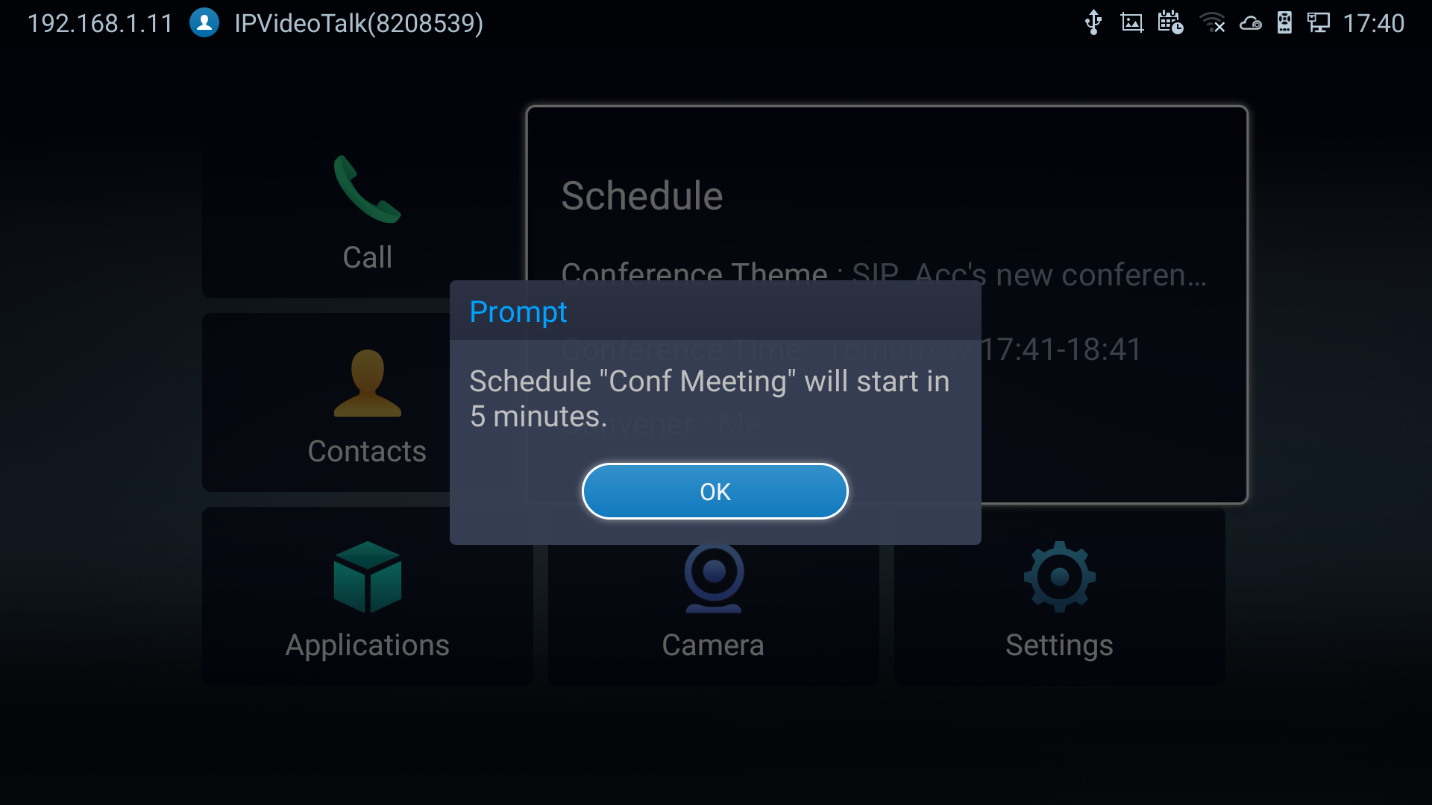
For more information about your IPVideoTalk services, settings, how to manage accounts and schedule meetings, please check IPVideoTalk user manual from http://www.ipvideotalk.com
Conference Control
IPVideoTalk Meeting Operations
If GVC3220 joins an IPVideoTalk meeting as a participant and the host is any WebRTC client, the participant could click on button
![]() from conference control screen to raise hand and attract host attention to indicate that he/she wants to be unmuted or needs any help.
from conference control screen to raise hand and attract host attention to indicate that he/she wants to be unmuted or needs any help.
The raised hand status of GVC3220 participants could be checked from Participants List on Host WebRTC Client, as shown in below figure
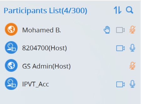
-
The WebRTC host can proceed as follows.
-
Force hand down by clicking on button
 .
.
- Enable of disable participants video/audio feed using the available camera and mic icons.
-
Force hand down by clicking on button
-
The host GVC3220 can do the below operations:
- Lower hand of a participant:
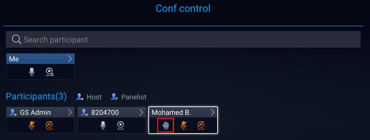
- Lower hand of all participants: The host can go to “Conf Control” and click on more options (Next to Me) to bring the hand icon.
-
 Mute/Unmute
-
 Enable/Disable participants’ camera
 Enable/Disable participants’ camera
Start Cloud Recording
During an IPVideoTalk meeting/webinar, under Call Screen of host GVC the users can control cloud recording.
- To start/stop cloud recording, users could click on “Record” button under host GVC3220 LCD 🡺 Call
screen, or press
![]() shortcut key on remote control to Open/Close server recording :
shortcut key on remote control to Open/Close server recording :
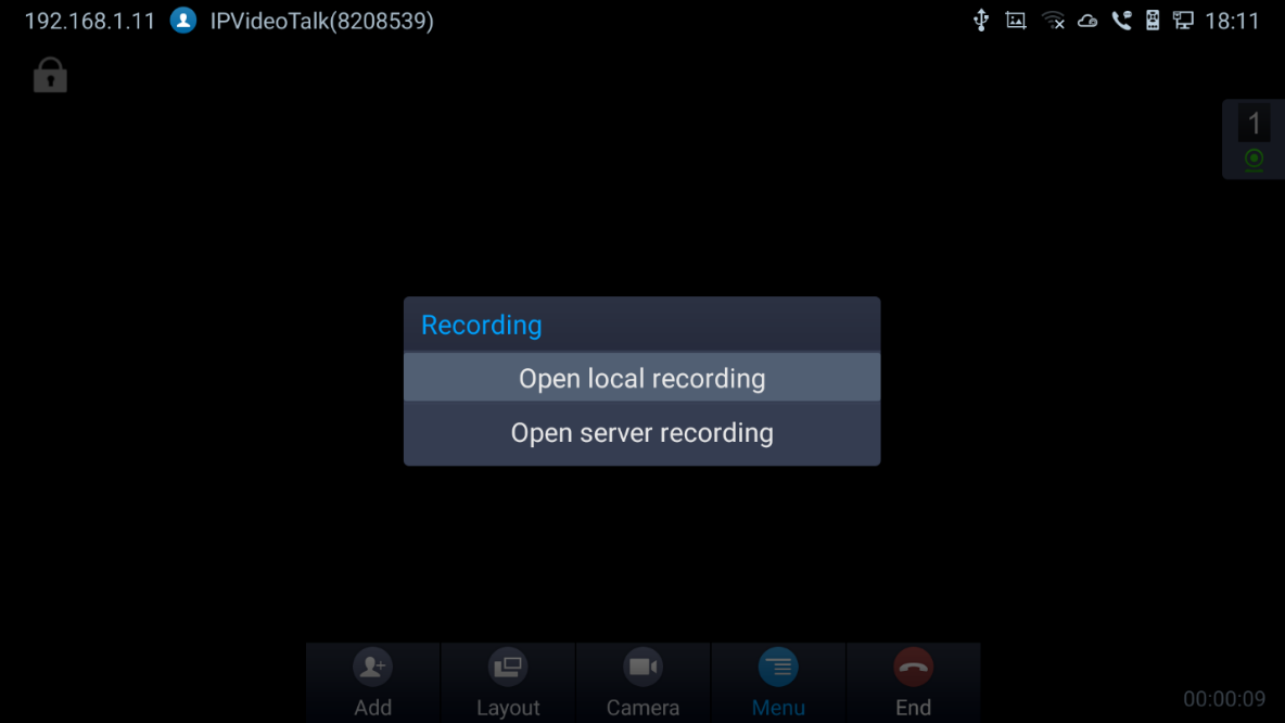
- There will be an icon
 shown on the left upper corner of host GVC as well as all other participants to indicate the server recording is in progress
 - Users could log in to IPVideoTalk Enterprise web portal 🡺 Recordings page to View/Download/Delete the recordings for the cloud meetings/webinars:
 shown on the left upper corner of host GVC as well as all other participants to indicate the server recording is in progress
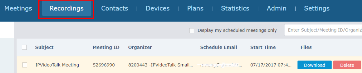
GVC3220 WEB UI FEATURES
GVC3220 embedded Web server responds to HTTP/HTTPS GET/POST requests. Embedded HTML pages allow users to configure the application device through a Web browser such as Mozilla Firefox, Google Chrome etc.
Accessing GVC3220 Web GUI
The IP address of the GVC3220 is displayed on top let of display device.

To access GVC3220 Web GUI:
1. Ensure your GVC3220 is properly powered up and connected to the Internet.
2. The IP address of the GVC3220 will show on the top status bar of the connected display device
(e.g., TV) via HDMI.
3. Type the IP address in your PC’s browser (see figure below).
4. Enter username and password to login. (The default administrator username is “admin” and the default random password can be found at the back sticker on the GVC3220).
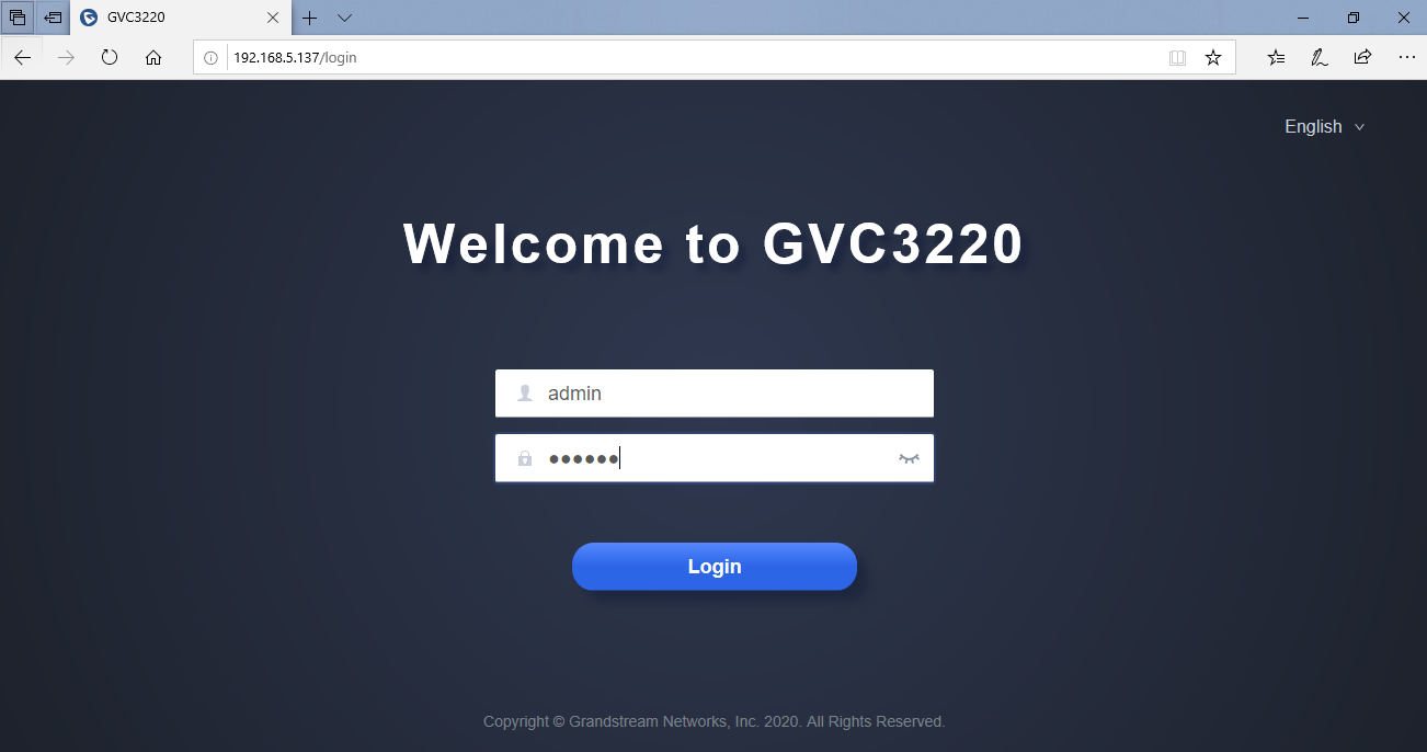
Share Screen (Without Login)
Starting firmware 1.0.1.35, “Share Screen” is available on the web UI without login.
- Click on “Share Screen”

- A prompt will ask to enter the code and press “Turn on Sharing”.
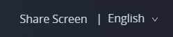
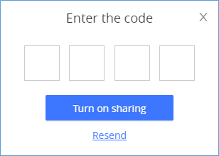
The code is automatically generated and will be displayed on the connected TV.
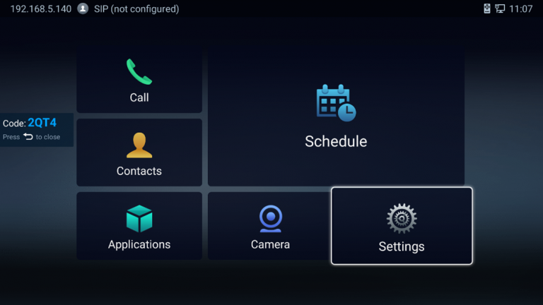
3. Select the screen to share and press “Share” button.
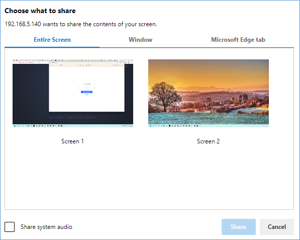
Saving Changes
When changing any setting on GVC3220 web UI, users need to submit them by pressing the
![]() button on the bottom of the page, and then, click the
button on the bottom of the page, and then, click the
![]() button on the top of the page to apply the configuration changes.
button on the top of the page to apply the configuration changes.
Definitions
This section describes the 6 options on GVC3220 Web GUI. Please view Settings, Maintenance and Status specifications in Administration Guide.
- Call: Users could start video conference and control conference from Web GUI.
- Account: SIP, IPVideoTalk, H.323, Bluejeans and Zoom account configuration
- Call features: Audio/Video call settings
- Network Settings: Ethernet, Wi-Fi, OpenVPN …
- System Settings: Power, Date&Time, Language …
- Device Control: Video Control …
- App: LDAP, Broadsoft, 3rd party Apps …
- Maintenance: Upgrade, Troubleshooting, Reboot …
- Status: Account Status, Peripheral Status, Network Status, System Info and Remote Control
Users can log in as an administrator or a normal user. The following table shows the web pages accessible by normal user and administrator. It is recommended to change the default password for user and administrator after login for the first time.
User Type | Username | Default Password | Accessible Web Pages |
Normal User | user | 123 |
Note: Limited Options. |
Administrator | admin | A random string that can be found on the MAC Tag in the back of the GVC3220 | All pages |
Toolbar
The web UI tool bar is on the upper right corner of the web UI page.

- Search button
 : User can search Web GUI options by clicking the button to display a search bar.
- DND: It is used to turn on/off DND mode. Once it is enabled, the DND text will turn into red and all incoming calls will be rejected.
- Share screen: (HTTPS required) Users need to switch the web interface to HTTPS before using this function. It allows to share the screen directly from web interface.
- Remote Control: Click to bring up virtual remote control panel.
- English: Select the display language for the web UI.
- Admin: Log out from the web UI.
Call Page
GVC3220 Web UI call page is shown below. Users could make calls and initiate conference from Web UI.
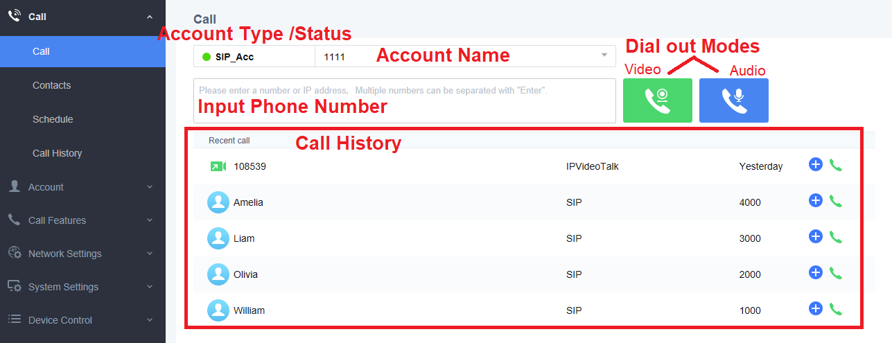
Contacts Page
This page lists Contacts, Schedule, and Call History.
Web GUI Contacts
Users could search/add/delete/edit contacts on web page. The operations will be synchronized and can be viewed from LCD as well. The web UI contacts page is as shown below.
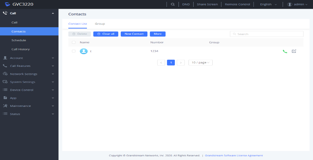
-
Click on
 next to the contact to dial the contact.
-
Click on
 to open more options such as export, import and download contact:
- Select “Import”, “Export” or “Download” options and users will find a pop screen with needed configuration. Refer to the Admin guide for more details.
-
Click on
 to popover Add Contact screen. Fill in contact information and save.
-
Click on
 and users will find Edit Contact screen on the right. Edit contact information and save.
-
Click on the checkbox
 for “Delete” and users can select the contacts to delete from GVC3220.
Groups
GVC3220 supports up to 5-way video conference. If there are more than 4 conference members, only the first 4 members in the group will be dialed.
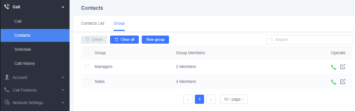
-
Click on
next to the group to call the contacts in the group.
-
Click on
 and users will find Add Group screen on the right. Select group members from existing contacts and save.
-
Click on
and users will find Edit Group screen on the right. Edit Group information and save.
-
Click on the checkbox
for “Delete” and users can select the groups to delete from GVC3220.
Schedule
Conference can be scheduled, edited, and deleted from web UI. See figure below. Please refer to chapter Schedule for more details for each option.
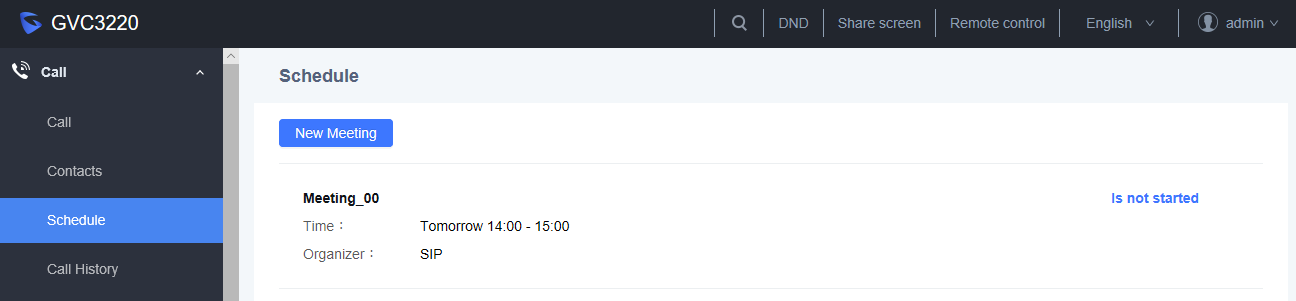
-
Click on
 to popover Add Schedule screen. Click on “Save” after configuring the schedule.
- Move the cursor to the scheduled conference where the scheduled time is displayed,
-
The button
 will appear for the user to dial out immediately.
-
Click
 for the Edit Schedule screen.
-
Click
 to delete the scheduled meeting.
Call History
From web UI, users could also access Call history, which is synchronized with the call history from LCD.
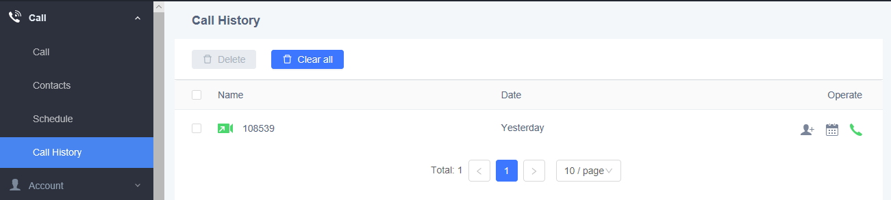
The call history details will be displayed upon selecting an entry. Users can move the cursor to the call history time to re-schedule the call by clicking on
![]() , dial out immediately by clicking on
, dial out immediately by clicking on
![]() , or click
, or click
![]() to save in contacts. Also,
to save in contacts. Also,
![]() to delete all the logs.
to delete all the logs.
Device Control Page
Users could add preset and manipulate PTZ control on this section.
- Preset Control: Move the cursor to one preset zone then click to Edit.
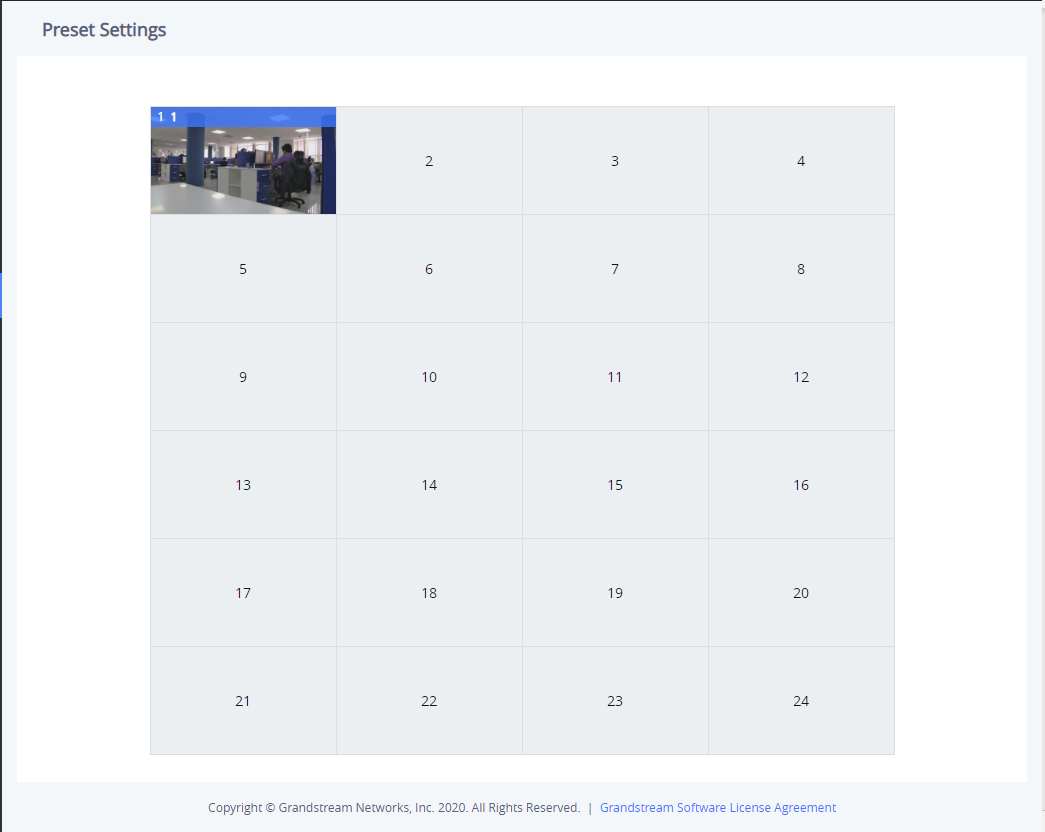
- Camera Control: Use the available Mode button and direction keys to configurations the camera position accordingly.
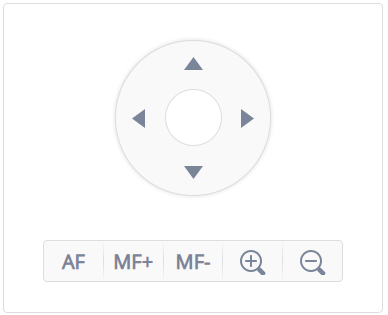
FACTORY RESET
Users could reset GVC3220 to factory settings via the following ways: Reset via local GUI, via Web page, via the reset hole on the back panel of GVC3220. Factory reset will delete configuration info and syslog info.
Reset via LCD
Go to GVC3220 LCD idle screen 🡺 Settings 🡺 Factory Reset, click on the “Reset” button to bring up the prompt box as shown below. Click “OK” to reboot the device and restore factory settings.
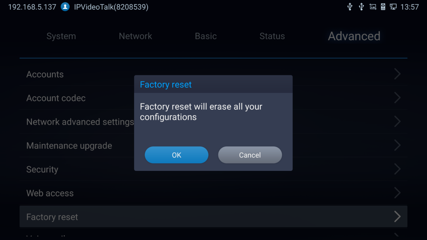
Reset via Web UI
- Log in GVC3220 Web UI 🡺 Advanced Settings 🡺 Upgrade, the “Factory Reset” option is on the bottom of the page.

2. Click the “Reset” button to bring up the prompt box as shown below. Click “OK” to reboot the device and restore factory settings.
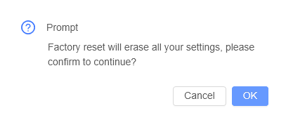
Reset via Reset Hole
There is a Reset hole on the back panel of GVC3220, use a small pin to hold against the Reset hole for more than 10 seconds to restore factory settings.
EXPERIENCING GVC3220
Please visit our website: http://www.grandstream.com to receive the most up-to-date updates on firmware releases, additional features, FAQs, documentation and news on new products.
We encourage you to browse our product related documentation, FAQs and User and Developer Forum for answers to your general questions. If you have purchased our products through a Grandstream Certified Partner or Reseller, please contact them directly for immediate support.
Our technical support staff is trained and ready to answer all of your questions. Contact a technical support member or submit a trouble ticket online to receive in-depth support.
Thank you again for purchasing Grandstream Video Conferencing System, it will be sure to bring convenience and color to both your business and personal life.
* Android is a trademark of Google LLC.

HDMI, the HDMI Logo, and High-Definition Multimedia Interface are trademarks or registered trademarks of HDMI Licensing LLC in the United States and other countries.
CHANGE LOG
This section documents significant changes from previous versions of GVC3220 user manuals. Only major new features or major document updates are listed here. Minor updates for corrections or editing are not documented here.
Firmware Version 1.0.1.37
- Added ability to use zoom/PTZ functions with the camera in GVC3220 when using the WebEx application. [Remote Control]
- Added ability to use zoom/PTZ functions with the camera in GVC3220 when using the Teams application and ZOOM application. [Using the Remote Control]
Firmware Version 1.0.1.35
- Added screen sharing when web is not logged in. [Web GUI Sharing]
- Added IPVT layout function. [Device Layout]
- Added IPVT FECC function.[FECC Camera Control in Conference]
- Added USB pairing of GMD. [Connecting GMD1208 to GVC3220]
- Added GMD acoustic echo cancellation feature. [Microphone and Speaker]
- Added ability to use camera zoom and PTZ when using Teams or Zoom application. [Remote Control]
- Added camera PTZ/zoom functionalities in 3rd party apps such as Microsoft Teams and Zoom. [Using the Remote Control]
- Improved device performance of 3rd party meetings such as system stability and echo issues.
- This is the initial version.