


Introduction
The GWN7302 is an outdoor PtP/PtMP Fixed Wireless Bridge designed for Point-to-Point (PtP) and Point-to-MultiPoint (PtMP) deployments in business and infrastructure environments. It enables stable, long-distance wireless links up to 5 km between remote locations with a clear line of sight.
Unlike traditional Wi-Fi access points, the GWN7302 is built for transparent Layer-2 bridging, allowing full extension of the local network across sites. It carries DHCP, VLAN, and management traffic just like an Ethernet cable.
With 5GHz directional antennas, 2×2:2 MIMO, and TDMA-based communication, it helps reduce interference and maintain consistent performance. The IP66-rated enclosure makes it suitable for outdoor deployment in locations such as construction sites, security camera poles, parking areas, and multi-building campuses.
Deployment supports:
- PtP Mode – One Master connected to one Slave
- PtMP Mode – One Master connected to up to four Slaves
The setup process is streamlined using:
- One-Key Pairing
- LED-based signal alignment
- Integrated Web UI, GWN App, and GDMS Cloud
Note: The GWN7302 is designed for infrastructure links and does not serve as a general Wi-Fi access point.
This manual includes full guidance for installation, setup, pairing, alignment, and management.
Product Overview
Technical Specifications
Category | Specification |
Wi-Fi Standards | IEEE 802.11 a/n/ac/ax |
Antennas | 2 single frequency antennas 5GHz x 2, gain 13.5dBi Beamwidth 5GHz: H:30°, V:30° |
Wi-Fi Data Rates | 5G: IEEE 802.11ax: 7.3 Mbps to 2402 Mbps IEEE 802.11ac: 6.5 Mbps to 1732 Mbps IEEE 802.11n: 6.5 Mbps to 300 Mbps IEEE 802.11a: 6, 9, 12, 18, 24, 36, 48, 54 Mbps *Actual throughput may vary depending on many factors including environmental conditions, distance between devices, radio interference in the operating environment and mix of devices in the network |
Frequency Bands | 5GHz Radio:5150 – 5895 MHz *Not all frequency bands can be used in all regions. |
Channel Bandwidth | 5G: 20, 40, 80, and 160 MHz (x2) |
Wi-Fi and System Security | WPA2-PSK, WPA3-PSK, anti-hacking secure boot and critical data/control lockdown via digital signatures, unique security certificate and random default password per device |
MIMO | 2×2:2 5GHz |
Coverage Range | Up to 5 kilometers *Coverage range can vary based on environment |
Maximum TX Power | 5G: 26dBm *Maximum power varies by country, frequency band and MCS rate |
Receiver Sensitivity | 5G: 802.11a: -92dBm@6Mbps, -74dBm@54Mbps; 802.11n 20MHz: -73dBm@MCS7; 802.11n 40MHz: -70dBm@MCS7; 802.11ac 20MHz: -67dBm@MCS9; 802.11ac 40MHz: -63dBm@MCS9; 802.11ac 80MHz: -59dBm@MCS9 802.11ax MIMO: -60dBm@MCS11; 802.11ax 40MHz: -58dBm@MCS11; 802.11ax 80MHz: -56dBm@MCS11; 802.11ax 160MHz: -52dBm@MCS11 |
Management SSID | Single 5G |
Point to Multipoint | 1 to 4 |
Network Interfaces | 2 x 10/100/1000Mbps Ethernet |
Auxiliary Ports | 1x Reset and Pairing Pinhole |
LEDs | 1 tri-color LED for device tracking and status indication 3 x LED for signal strength 2 x LED for network port status |
Network Protocols | IPv4, 802.1Q, 802.1p, 802.11e/WMM |
QoS | 802.11e/WMM, VLAN, TOS |
Network Management | Embedded controller can manage via Web access GDMS Networking offers remote management via SSH tunneling GWN APP offers on-site management without LAN |
Power and Green Energy Efficiency | DC: +24VDC (Compatible with 16VDC-48VDC), PoE/PoE+: 802.3af/at PSE output: max13W with PoE+ Input/max 25W with +24VDC/2A input |
Environmental | Operation: -30°C to 60°C Storage: -30°C to 70°C Humidity: 5% to 95% Non-condensing |
Physical | Unit Dimension: 180mm x 102mm x 38mm |
Mounting | Wall mount or pole mount, kits included |
Package Content | GWN7302 PtP/PtMP Fixed Wireless Bridge, Mounting Kits, Quick Start Guide |
Weatherproof Grade | IP66-level weatherproof capability when installed vertically |
Surge Protection | 8KV |
Compliance | FCC, CE, RCM, IC |
GWN7302 Technical Specifications
Hardware Installation
Package Contents
The GWN7302 package includes the following components required for installation and setup:
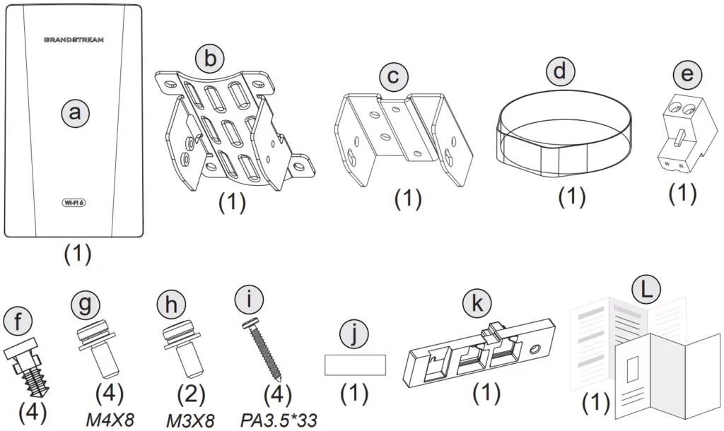
Letter | Qty | Item Description |
a | 1 | GWN7302 Device |
b | 1 | Wall/Pole Bracket |
c | 1 | Device Bracket |
d | 1 | Steel Strap |
e | 1 | Terminal Power Adapter (24V input) |
f | 4 | Expansion Bolts |
g | 4 | Screws (M4×8) |
h | 2 | Screws (M3×8) |
i | 4 | Screws (PA3.5×33) |
j | 1 | Adhesive Sticker |
k | 1 | Rubber Waterproof Accessory |
L | 1 | Quick Installation Leaflet |
Package Contents
Device Ports
The GWN7302 features:
- NET1 Port – PoE IN
- NET2 Port – PoE OUT
- RST/PAIR Button – for factory reset or one-key pairing
- Power Terminal – for 24V DC optional input
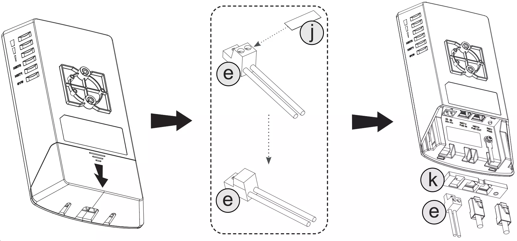
Port | Description |
NET1 (PoE IN) | Ethernet RJ45 port (10/100/1000 Mbps) supporting PoE/PoE+ input. Use this port to power the device via a PoE injector or switch. |
NET2 (PoE OUT) | Ethernet RJ45 port (10/100/1000 Mbps) with PoE/PoE+ output capability to power another PoE device (e.g., an IP camera or access point). |
RST / PAIR | Multi-function button used to: • Press and hold for 7 seconds to reset to factory settings • Tap once for One-Key Pairing during PtP/PtMP configuration |
Power Terminal (24V DC) | Power input via terminal block for 24V DC. Can be used if PoE is not available. |
Ports
Device Mount
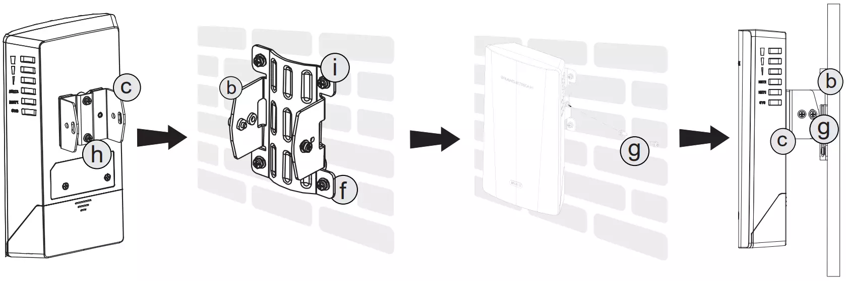
GWN7302 can be mounted on the wall or a metal bar. Please refer to the following steps for the appropriate installation.
Wall Mount
- Attach the Device Bracket
Use the M3 screws to secure the device bracket to the back of the GWN7302.
- Fix the Wall Bracket
Mount the wall/pole bracket to the wall using the expansion bolts and long screws..
- Hook & Secure the Device
Align the device bracket with the mounted wall bracket, hook it into place, and secure it using the screws for firm attachment.
- Tighten and Check
Ensure all screws are secure and the device is properly fixed and facing the correct direction.
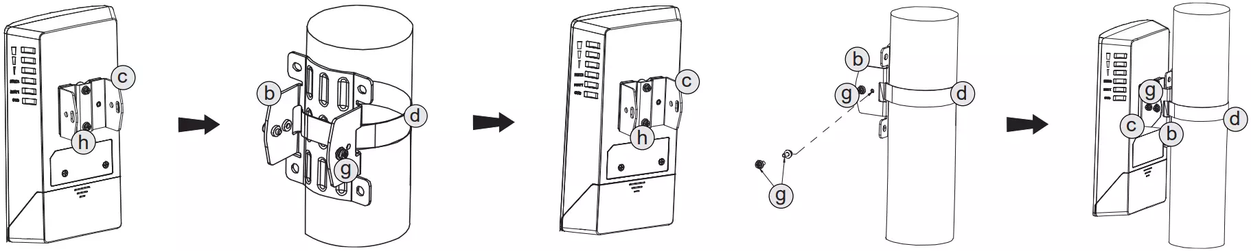
Pole Mount
- Attach the Device Bracket
Use the M3 screws to secure the device bracket to the back of the GWN7302.
- Fix the Pole Bracket
Insert the steel strap through the pole bracket and wrap it around the pole. Tighten the strap until the bracket is snug and level.
- Hook & Secure the Device
Align the device bracket with the mounted pole bracket, hook it into place, and secure it with screws for a firm and stable attachment.
- Final Check
Confirm the device is tightly mounted, facing the correct direction, and all fasteners are secure.
Rubber Waterproof Plug Installation
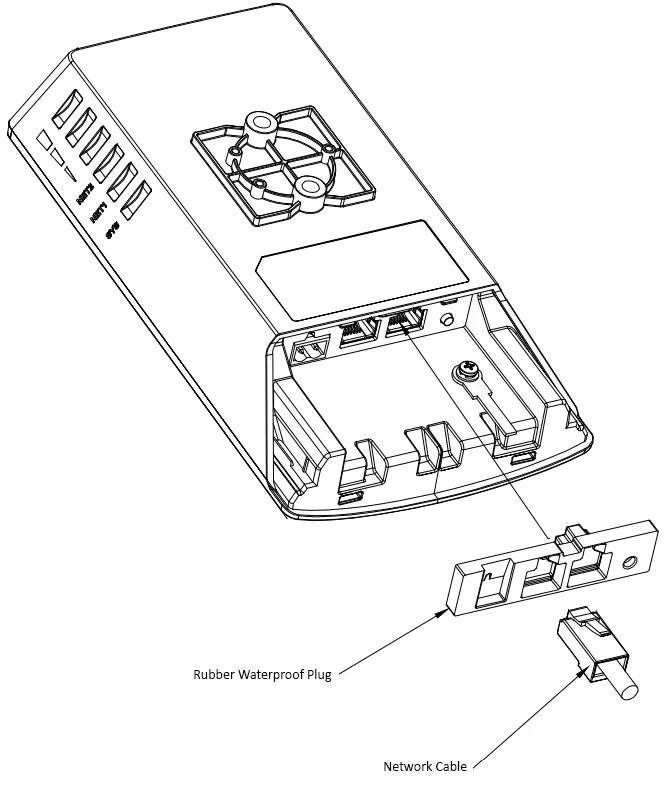
The GWN7302 includes a rubber waterproof plug used to seal unused ports and maintain IP66 protection for outdoor use. Depending on your power method and port usage (NET1, NET2, DC IN), the plug can be configured in two ways:
Case 1: Using only NET1 (PoE IN)
If you’re using only NET1 for both power and data (typical for most PtP deployments):
- You do not remove any rubber inserts.
- You insert the network cable (RJ45) directly through the main open port on the rubber plug.
- The other two plug sections (NET2 + DC IN) stay sealed.
Case 2: Using NET2 and/or 24V DC Input
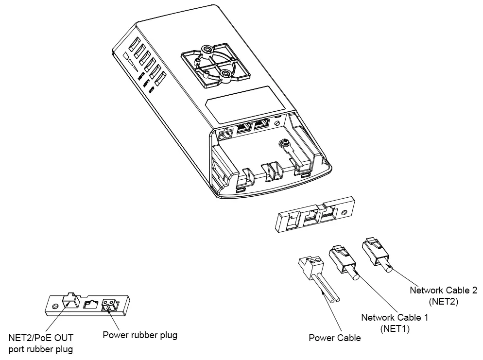
If you’re using NET2 (PoE OUT) to power another device (e.g., camera) and/or supplying power via the 24V terminal block:
- You need to remove the corresponding rubber seals from the backside of the plug:
- Remove the rubber cap for NET2 if you’re inserting a second Ethernet cable.
- Remove the rubber cap for DC IN if using a 24V terminal adapter.
- Insert the cables through the newly opened holes.
- Then fit the rubber plug into the main unit as usual.
Getting Started
Initial Access to the GWN7302
This section explains how to access the GWN7302 for the first time.
Pairing Guide (Recommended): Pairing is the most important step when deploying the GWN7302 in PtP or PtMP mode. This user manual provides a high-level overview only. For full step-by-step pairing instructions and best practices (including RST/PAIR button pairing), refer to the dedicated GWN7302 Pairing Guide
Option A: GWN App
When powered on, the GWN7302 broadcasts a Management Wi-Fi network for initial setup. The SSID is automatically generated and appears in the format: GWN7302_XXXXXX (where XXXXXX is the last characters from the device MAC address).
To access the device from a phone:
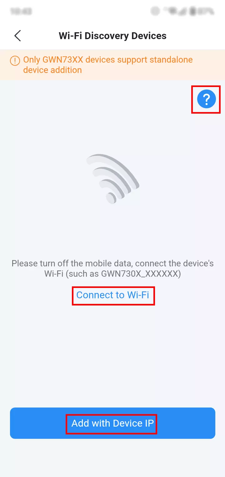
- Connect your phone to the broadcast SSID (for example,
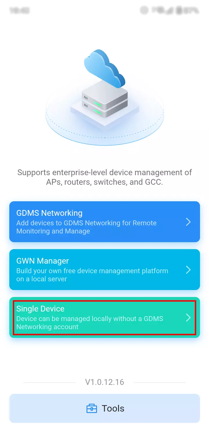
GWN7302_XXXXXX). - Open the GWN App and select Single Device.
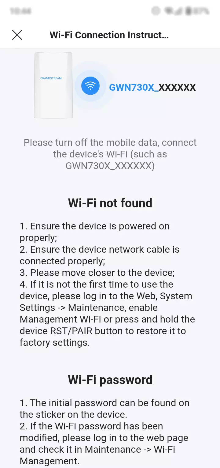
On the discovery page, tap Connect to Wi-Fi to search for the device. If the device is not detected, tap the ? icon to view connection guidance.
or select Add with Device IP to log in manually.
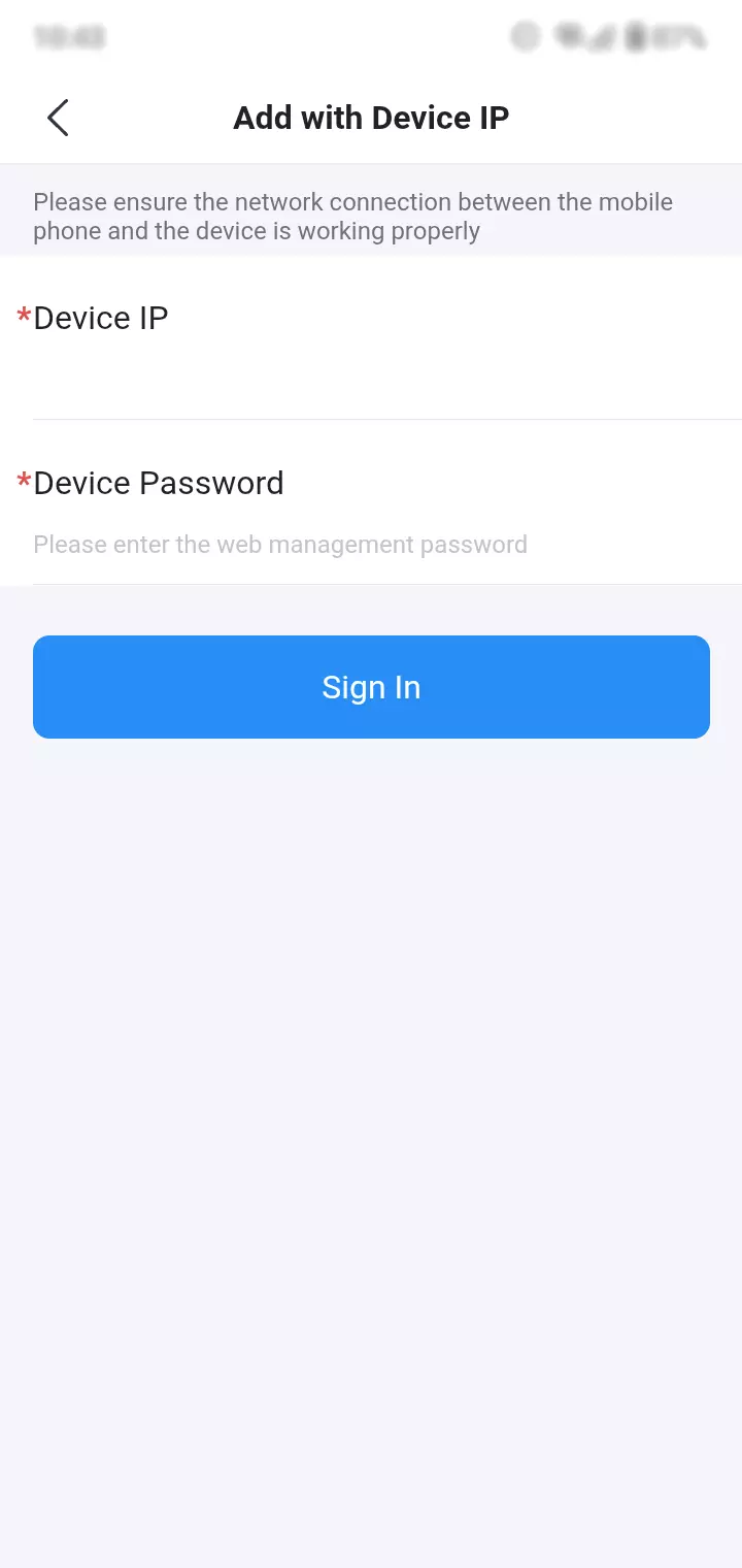
If you choose Add with Device IP, enter the device IP address and the device password (Web UI login password), then tap Sign In.
This method requires that your phone can reach the device IP on the same network.
For more details, check the GWN7302 Pairing Guide
Option B: MAC address or GWN Discovery Tool
Use this option when the GWN7302 and your computer are connected to the same local network (LAN), for example, connected to the same router or switch.
Method 1: Access using the device’s local URL (MAC-based)
Locate the MAC address on the device label, then enter the following in a browser: https://gwn_MAC Address.local
Example: If the MAC is C0:74:AD:8C:4D:F8, enter: https://gwn_c074ad8c4df8.local
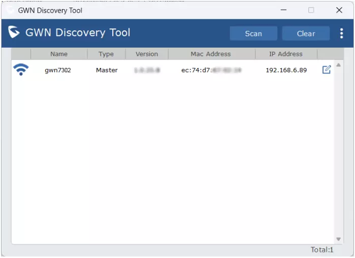
Method 2: Access using the GWN Discovery Tool
Run the GWN Discovery Tool, click Scan, then use the discovered IP address to open the Web UI.
Web UI Login
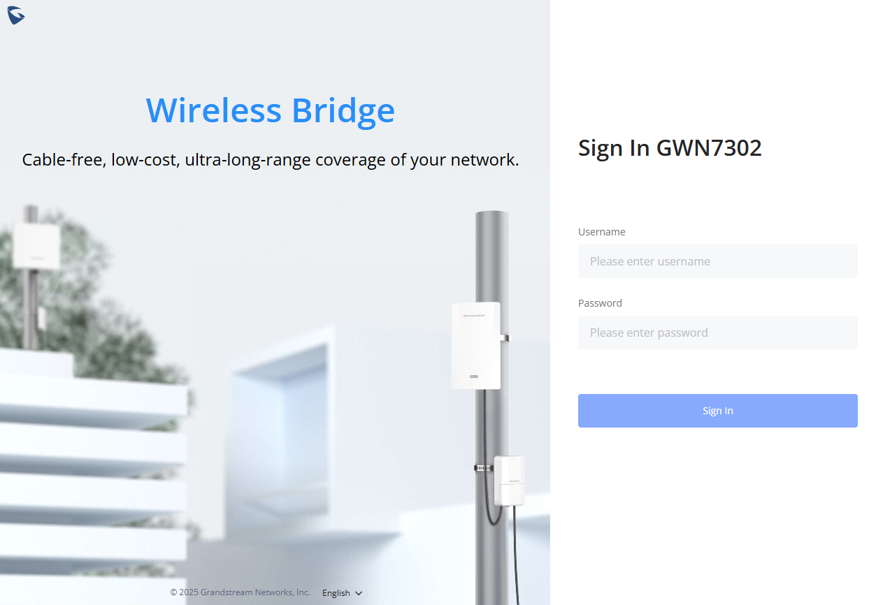
Log in using:
- Username:
admin - Password: the default random password printed on the device label (unless previously changed).
- Make sure the device is not already paired to another master or controller. If so, unpair or factory reset it first.
- It is the customer’s responsibility to ensure compliance with local regulations for frequency bands, transmit power, and others.
- To manage remotely, use the GDMS platform: https://www.gdms.cloud.
For more details, check the GWN7302 Pairing Guide
LED Indicators
The LED indicators on the GWN7302 provide at-a-glance feedback for device status, pairing progress, network connectivity, and link quality. These indicators are especially useful during installation, antenna alignment, and troubleshooting.
LED | Status | Meaning |
Sys (System) | Solid Yellow | Disconnected after pairing (Slave). |
Solid Pink | Device powered on & ready (factory default Slave mode or Pairing in progress). | |
Blinking Pink | Discovering the device and establishing a connection. | |
Rapidly Blinking Pink | Pairing confirmed (the RST/PAIR button was successfully pressed on the Slave device). | |
Solid Blue | Paired successfully, link established. | |
Solid Red | Pairing failed. | |
Blinking Blue | Configuration update in progress | |
Blinking green | Firmware update in progress | |
Solid green | The firmware update successful/rebooting | |
Blinking Red | Restore factory | |
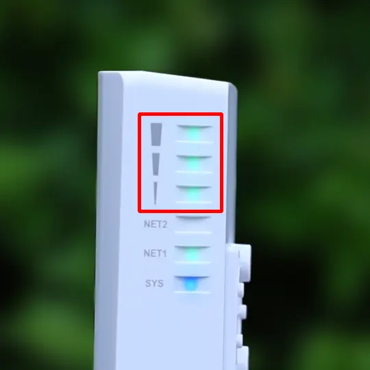
Signal LEDs (3 bars) | 1–3 Green bars | Slave: Link quality between this device and the paired Master. 3 LEDs turn blinking green in cycle when waiting to be discovered by Master. |
Master: All 3 LEDs turn solid green when role is active. 3 LEDs turn blinking green in cycle when scanning Slaves. | ||
NET1 (PoE IN) | Solid/Flashing Green | Ethernet link or data activity (PoE input). |
NET2 (PoE OUT) | Solid/Flashing Green | Ethernet link or data activity (PoE output). |
LED Indicators
Rebooting or Logging Out
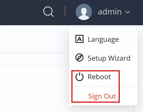
The Reboot and Logout options are located in the top-right corner of the web interface under the admin menu.
- Reboot: Click Reboot to restart the device. This will briefly interrupt the wireless bridge and any connected devices.
- Logout: Click on Logout to securely exit the web interface. You will need to log in again to access the settings.
Search
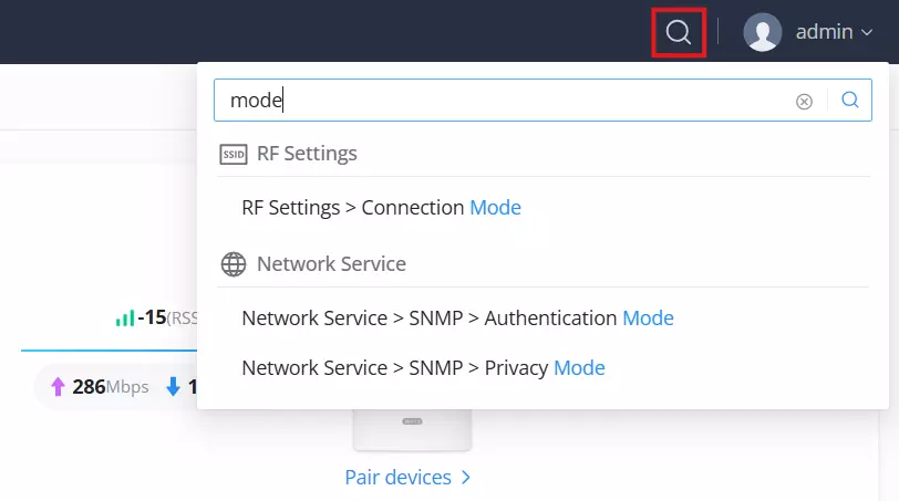
The GWN7302 Web UI includes a built-in Search Bar for quick navigation. It’s located in the top-right corner of the interface, next to the admin profile.
How to Use:
- Click the magnifying glass icon.
- Type a keyword (e.g., “mode”, “SSID”, “IP”, etc.).
- Matching settings and menu items will appear instantly.
This feature helps you jump directly to RF settings, network services, or any advanced option without browsing through each tab manually.
Setup Wizard
The Setup Wizard is a built-in configuration flow that simplifies the initial setup of the GWN7302 for both PtP and PtMP deployments. It’s ideal for first-time installation or post-reset reconfiguration.
The wizard appears automatically:
- On first login to a factory-reset device
- After manually selecting “Setup Wizard” from the admin menu in the top-right corner of the Web UI
The wizard can be re-run at any time without resetting the device.
Configuration Flow
The wizard consists of three main steps:
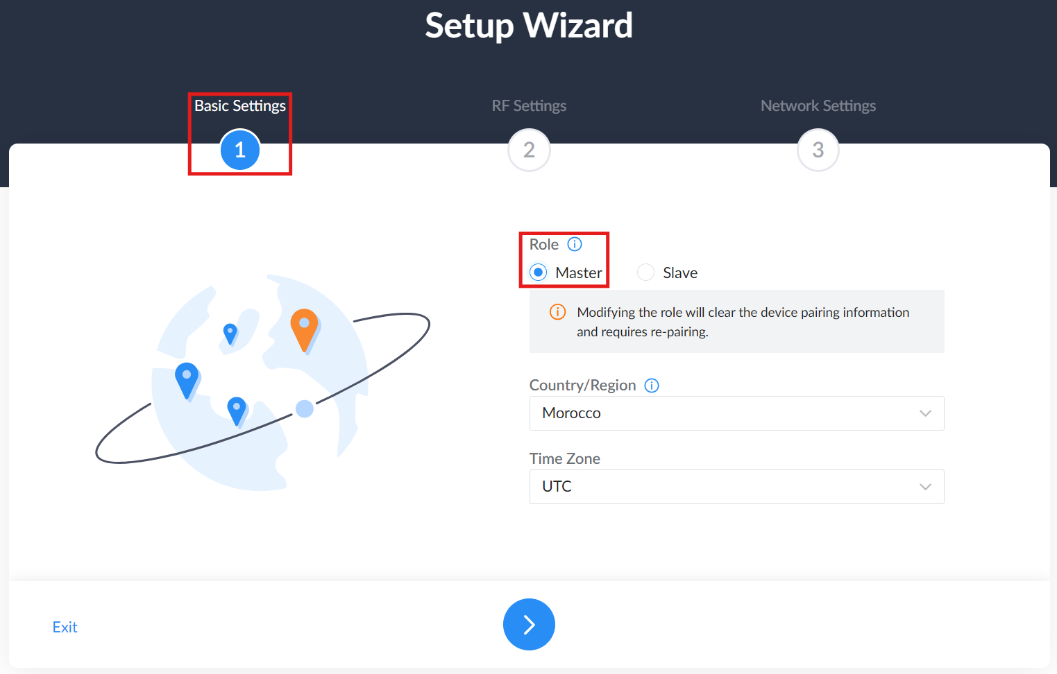
1. Basic Settings
- Select Device Role:
- Master: Transmits the bridge signal and typically connects to the uplink network, such as a switch or router.
- Slave: Receives the bridge signal and extends the network to a remote site, typically connecting to terminal devices such as cameras.
- Set Country and Time Zone
2. RF Settings
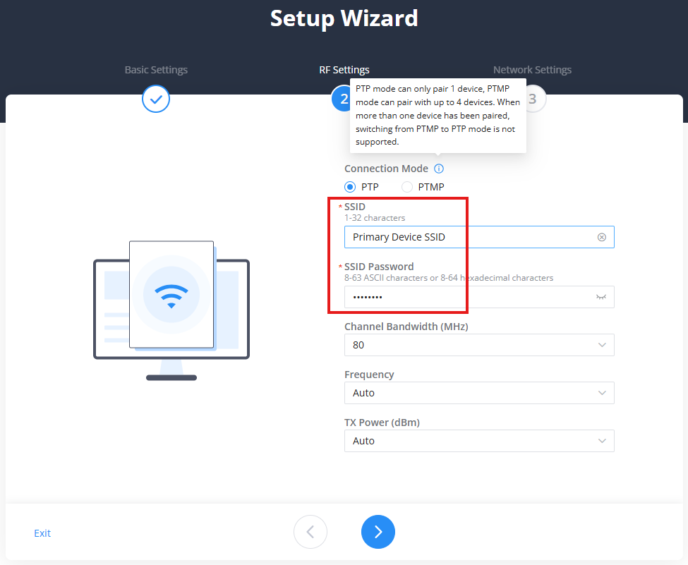
- Choose Connection Mode:
- PtP (one Slave)
- PtMP (up to 4 Slaves)
- Configure:
- SSID & Password
- Channel Bandwidth (20/40/80 MHz)
- TX Power (Auto or Manual)
3. Network Settings
- Choose IP mode: DHCP (default) or Static
- If Static: Enter
- IP Address
- Subnet Mask
- Gateway
- DNS Servers
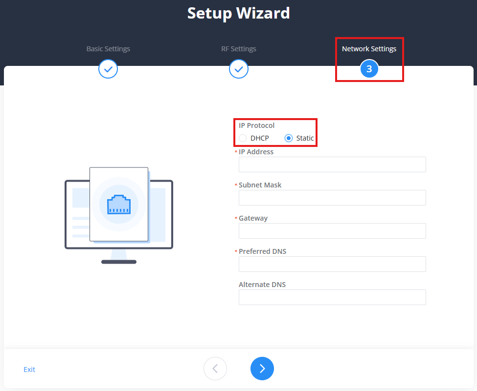
For more details, including full pairing steps and RF tuning, visit the official guide: GWN7302 Pairing Guide
Overview
Overview page
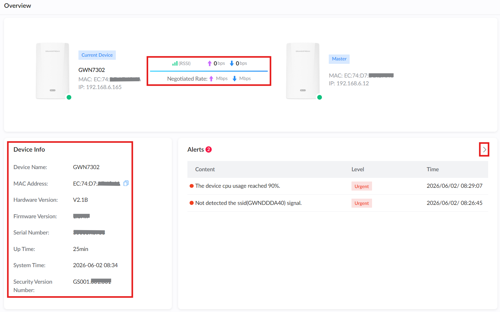
The Overview page provides a central dashboard for checking the current status of the GWN7302, including device information, bridge link status, alerts, and monitoring charts.
Topology and Link Status
The topology area shows the relationship between the current device and the paired device. It displays the device role, MAC address, IP address, link status, signal strength, throughput, and negotiated rate.
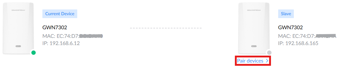
The device status indicator shows whether the paired device is online or offline:
• A green indicator means the device is online.
• A gray indicator means the device is offline.
When the paired device is online, the topology diagram displays real-time link information, including RSSI, upload/download throughput, and negotiated rate.
When the paired device is offline, the topology diagram shows the paired device with an offline status indicator and does not display active link statistics.
Click Pair devices to open the paired devices section and manage the device pairing.
Device Info
The Device Info panel displays basic information about the current GWN7302 device, including:
• Device Name
• MAC Address
• Hardware Version
• Firmware Version
• Serial Number
• Up Time
• System Time
• Security Version Number
Alerts
The Alerts panel displays recent system alerts with the alert content, severity level, and time. Click the arrow icon to view more alert details.
Monitoring
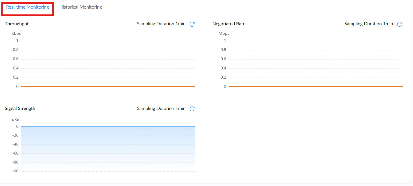
The monitoring area provides real-time and historical charts for the wireless bridge link.
Real-time Monitoring
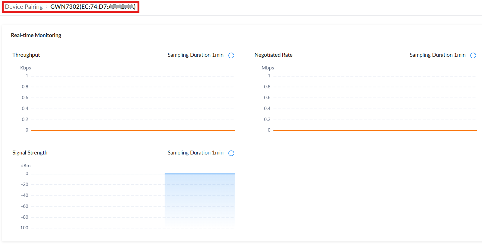
The Real-time Monitoring tab displays live monitoring charts for the bridge link. The charts include:
• Throughput: Displays current traffic throughput.
• Negotiated Rate: Displays the current negotiated wireless rate.
• Signal Strength: Displays the current signal strength in dBm.
Each chart uses a short sampling duration and can be refreshed from the refresh icon.
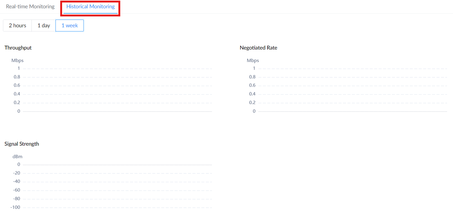
Historical Monitoring
The Historical Monitoring tab displays historical data for the bridge link. Use the available time range buttons, such as 2 hours, 1 day, or 1 week, to review previous performance data.
The historical charts include:
• Throughput
• Negotiated Rate
• Signal Strength
Network Status
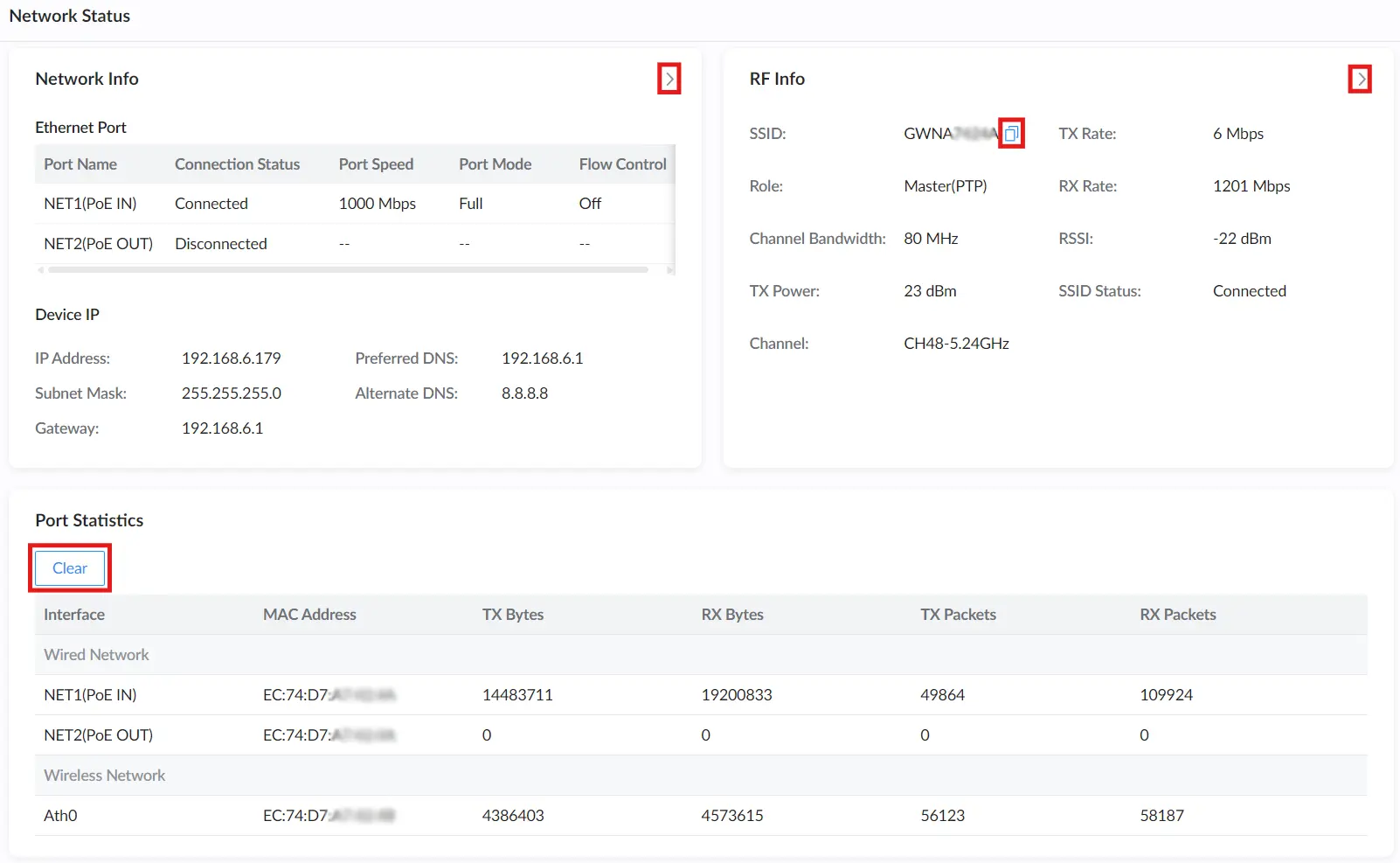
The Network Status page displays real-time connection and link quality information for the GWN7302 device. This view is crucial for verifying physical port status, RF link parameters, IP addressing, and monitoring overall traffic flow.
Ethernet Port Info
Displays the state of the two physical Ethernet ports:
| Field | Description |
|---|---|
| PoE IN | Main power and data input port (NET1). Should show Connected with 1000 Mbps. |
| PoE OUT | Optional PoE passthrough port (NET2) for powering devices like cameras. |
| Port Mode | Displays duplex mode (typically Full). |
| Flow Control | Shows whether flow control is active. |
Note: ➤ Clicking the arrow icon redirects to the Network Settings page for editing.
Device IP Info
Displays the current IP and DNS configuration of the unit:
- IP Address
- Subnet Mask
- Gateway
- Preferred / Alternate DNS
Note: Typically, these are assigned via DHCP unless a static IP was configured manually.
RF Info Summary
Shows key wireless parameters for the active PtP/PtMP link:
| Field | Description |
|---|---|
| SSID | The used secure SSID for bridge communication (not broadcast to clients). |
| Role | Displays the device role: Master (PtP) or Slave |
| Channel Bandwidth | e.g., 80 MHz |
| TX/RX Rate | Real-time link throughput |
| RSSI | Received signal strength indicator (e.g., -16 dBm) |
| TX Power | Configured transmission strength |
| SSID Status | The secure SSID for bridge communication (not broadcast to clients). |
| Frequency | Current operating frequency (e.g., CH100-5.5GHz(DFS)) |
Notes:
- ➤ Clicking the arrow icon redirects to the RF Settings page.
- Clicking the copy icon next to SSID copies the SSID to the clipboard for quick reference.
Port Statistics
Live statistics for wired and wireless interfaces:
| Metric | Description |
|---|---|
| Interface | Interface name (for example, NET1, NET2, Ath0). |
| MAC Address | MAC address of the selected interface. |
| TX Bytes / RX Bytes | Total transmitted/received bytes. |
| TX Packets / RX Packets | Total transmitted/received packets. |
Note: Click the “Clear” button to reset all statistics counters.
Device Pairing
From the Master device:
- Navigate to Device Pairing.
- Click the Add button to start pairing.

The Pairing Guide button opens the full GWN7302 Pairing Guide, which provides detailed pairing methods, preparation steps, and application scenarios.
Discovery – Finding Slave Devices
After clicking Add, the Device Pairing → Preparations page appears.
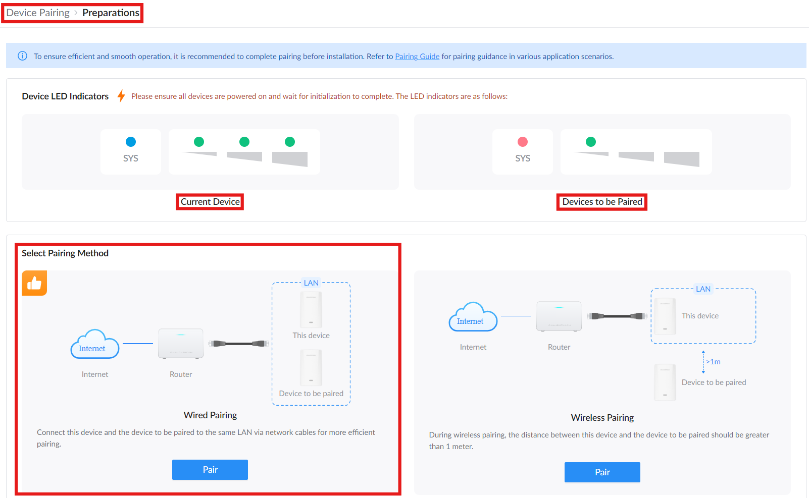
This page helps prepare both devices before discovery starts. Make sure all devices are powered on and wait for initialization to complete. Use the LED indicator reference to confirm the status of the Current Device and the Device to be paired.
Under Select the pairing method, choose one of the following:
Wired Pairing: Connect this device and the device to be paired to the same LAN using network cables. This method is recommended for more efficient pairing.
Wireless Pairing: Use this option when pairing wirelessly. Keep this device and the device to be paired more than 1 meter apart.
Click Go to Pair under the selected method to open the Add Paired Devices window.
After clicking Go to Pair, the Add Paired Devices window starts scanning for nearby Slave devices.
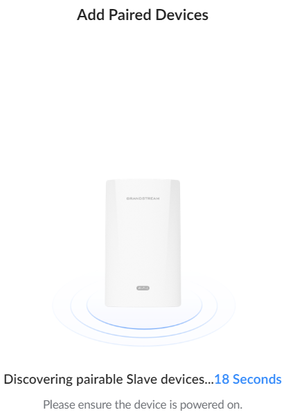
The Master displays “Discovering pairable Slave devices…” with a countdown while it searches (only for wireless pairing). Make sure the Slave device is powered on.
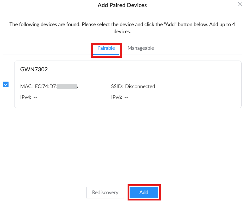
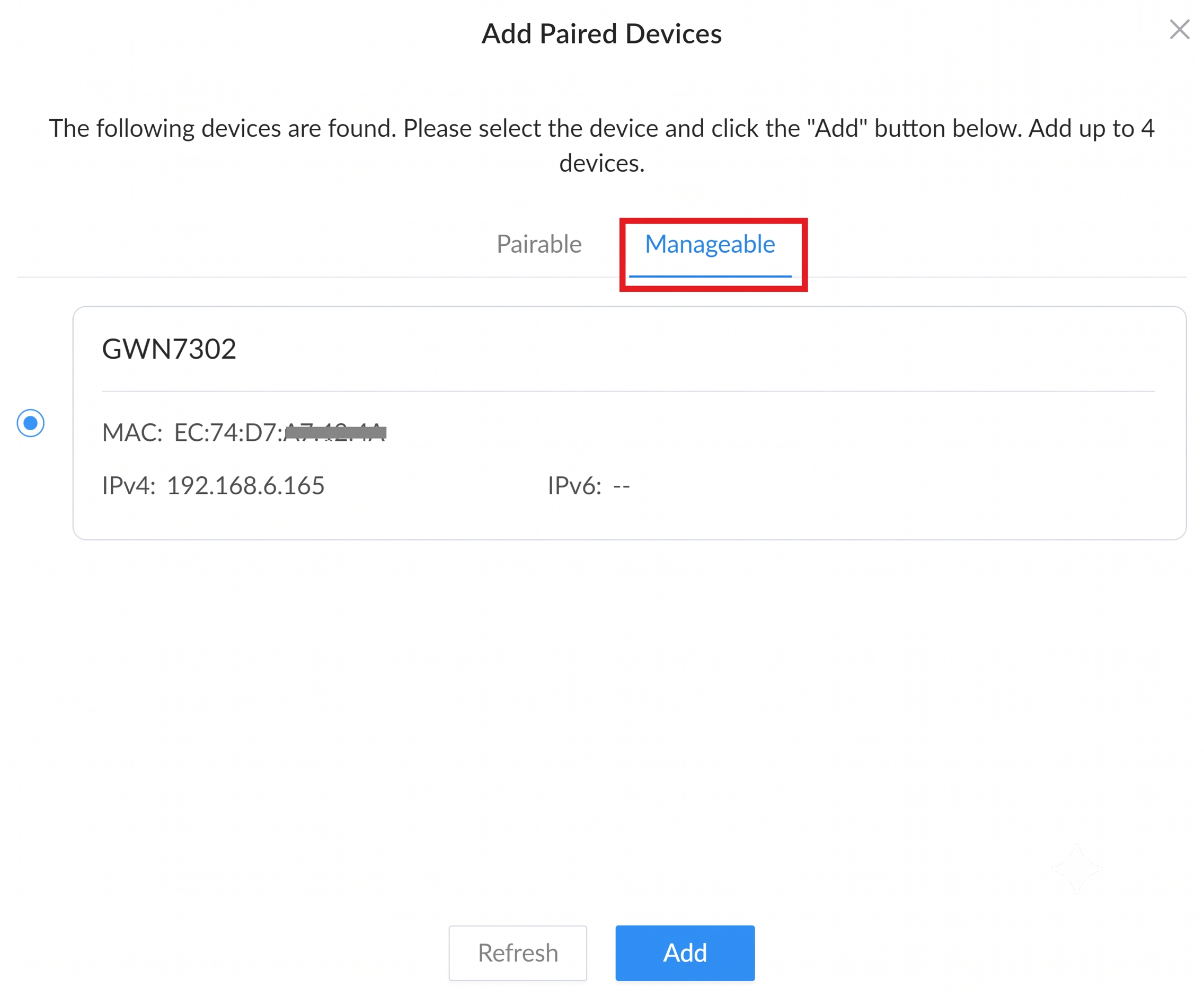
When devices are found, they appear in the Add Paired Devices window. The window includes two tabs: Pairable and Manageable.
If the list is still updating, wait for discovery to finish or click Rediscovery to scan again (only for wireless pairing).
Device List – Pairable & Manageable
After the scan, you’ll see a list of discovered devices:
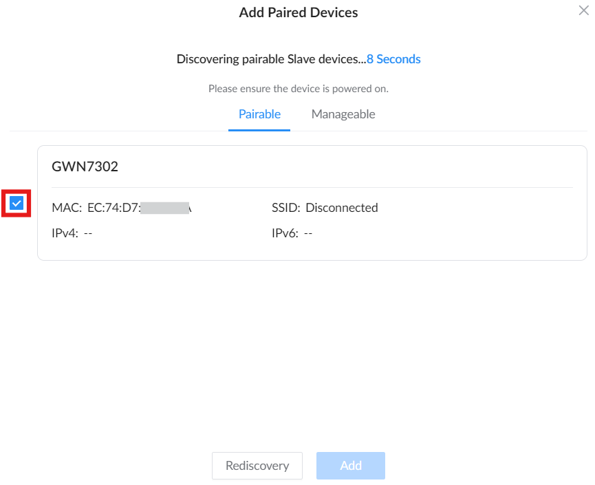
Use the Pairable tab for a Slave device that is free, reset, or not already paired. Select the device checkbox, then click Add.
Use the Manageable tab when the Slave device is already paired and needs to be added to this Master. Select the device, then click Add.
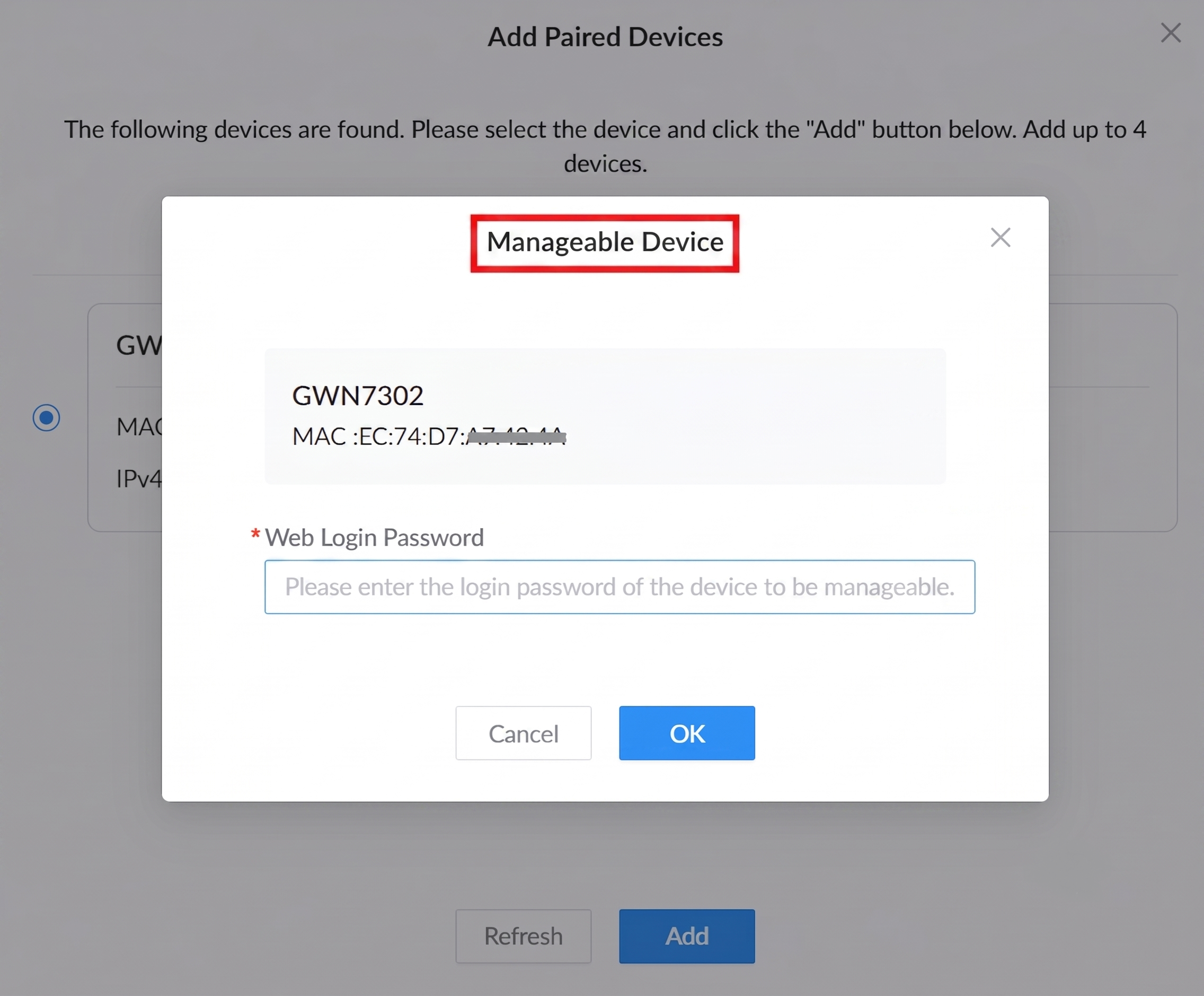
In the Manageable Device window, enter the Slave device’s Web Login Password, then click OK to allow this Master to take over the selected Slave.
Confirm & Complete Pairing
After clicking Add, the confirmation behavior depends on the selected pairing method.
For Wireless Pairing, the Add Paired Devices window starts a 30-second countdown and displays a message asking you to press the Slave device RST/PAIR button once within the countdown. Press the RST/PAIR button on the Slave device once to confirm pairing.
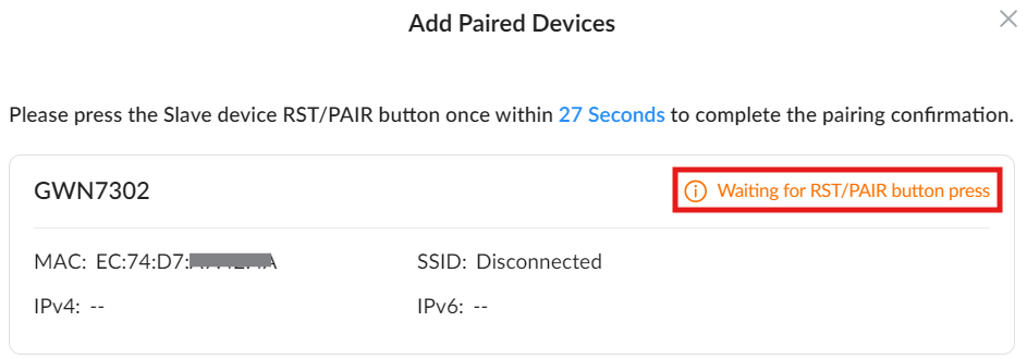
For Wired Pairing, no RST/PAIR button confirmation is required. After clicking Add, the device proceeds directly to pairing completion.
Successful Pairing or Failed Pairing
After pairing is completed, the device status changes to Paired successfully. The Slave may take a short time to initialize its configuration and go online.
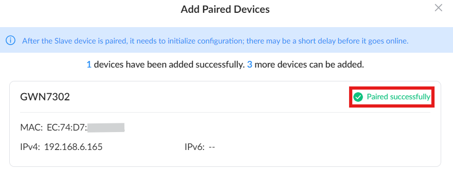
If failed: Status will show Failed to pair.
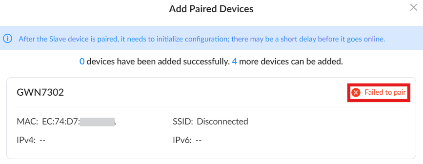
At this point, the wireless link between the Master and the Slave is active. To add more Slaves, repeat the same sequence: Add → discover → press the button on the Slave → check for “Paired successfully.”
If pairing fails, the status will show “Failed to pair”. In this case, reset the Slave again (hold RST/PAIR for 7 seconds), make sure it is powered on, within wireless range of the Master, and not already paired, then repeat the pairing process from Step 1.
If pressing the RST/PAIR button on the Slave is not possible (e.g., the device is mounted or hard to reach), you can log in to the Slave manually via its web UI.
Set the RF Settings (Role = Slave, Mode = PTP or PTMP, SSID & Password) to match the Master.
Once saved, the device will automatically pair when the Master performs Step 1 and Step 2. No need to execute Step 3.
For more detailed pairing instructions, pairing methods, and deployment scenarios, refer to the GWN7302 Pairing Guide
Monitoring & Actions – After Pairing
Once paired:
- You’ll see the device listed with real-time stats such as RSSI, SNR, Tx/Rx rate, etc.
- You can click:
- Delete icon to unpair the device (this triggers a reset).
- Diagnostic icon to view the traffic statistics and graphs.
- Login icon to directly access the Web UI of the paired device via its IP address.

RF Settings
The RF Settings page is where users configure the wireless bridge parameters that define how the GWN7302 establishes the PtP or PtMP link. This section differs slightly depending on whether the device is acting as a Master (Controller) or a Slave (Client).
For a complete explanation of pairing steps, setup wizard options, and RF behavior, refer to the full pairing guide: GWN7302 Pairing Guide
On the Master Device
The Master unit defines the wireless configuration that the Slave(s) will connect to. Key fields include:
These settings must be configured before pairing Slave devices.
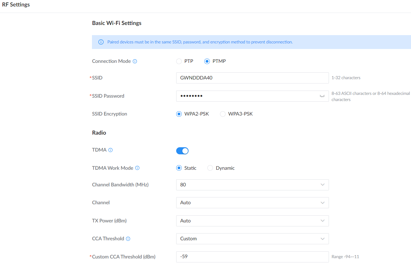
Field | Description |
Connection Mode | Select how the Master connects: PTP (one Slave) or PTMP (up to 4 Slaves). |
SSID | Wireless link name broadcast by the Master. Range: 1–32 characters. |
SSID Password | Wireless link password used by the Slave(s). Range: 8–63 ASCII characters or 8–64 hexadecimal characters. |
SSID Encryption | Select the encryption method for the wireless link (e.g., WPA2-PSK or WPA3-PSK). Note: WPA3-PSK will affect pairing. Please configure the Slave with the same SSID name, password, and encryption method as the Master, and then proceed with pairing once the SSID is connected. |
TDMA | Enables TDMA to improve wireless link stability, especially for PTMP deployments or when the signal strength is below -55 dBm. |
TDMA Work Mode (PTMP only) | Available when TDMA is enabled in PTMP mode. Static allocates time slots to all devices. Dynamic allocates time slots only to devices with data transmission. Use Static when a Slave cannot send enough data due to interference or long distance. |
Channel Bandwidth (MHz) | Sets the channel width used by the wireless link. Wider bandwidth may increase throughput but can be more sensitive to interference. |
Channel | Select Auto or a specific channel manually. Note: DFS channels may trigger radar detection behavior and may delay transmission or display prompts depending on regulatory requirements. |
TX Power (dBm) | Sets transmit power (Auto or manual). Configure according to coverage needs and local regulatory limits. |
CCA Threshold | Sets how the device determines if the channel is busy (Clear Channel Assessment). Usually left at default unless troubleshooting interference. |
Custom CCA Threshold (dBm) | Manual CCA threshold value when CCA Threshold is set to Custom. Range shown in UI: -94 to -11 dBm. |
RS Settings On the Master Device
On the Slave Device
The Slave unit needs to connect to the SSID defined by the Master. The page provides two methods:
- Manual Entry: Type in the SSID and password directly.
- Scan + Select: Click the Scan icon to discover nearby Slave devices. Then select the correct SSID and enter the password.
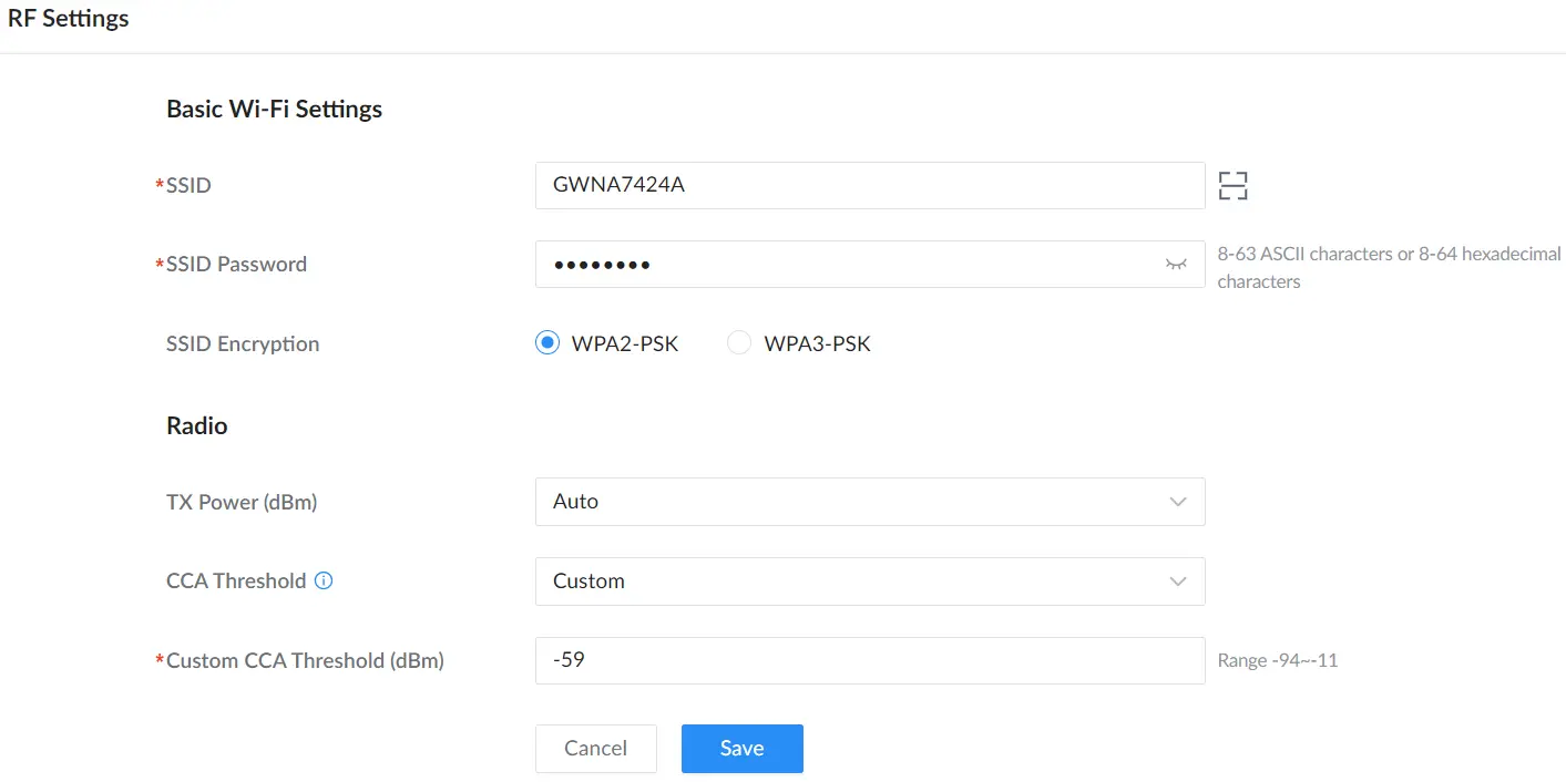
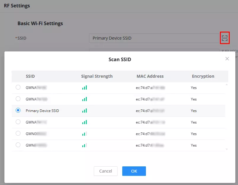
Note: The link SSID is encrypted and only used for communication between GWN7302 units.
Network Settings
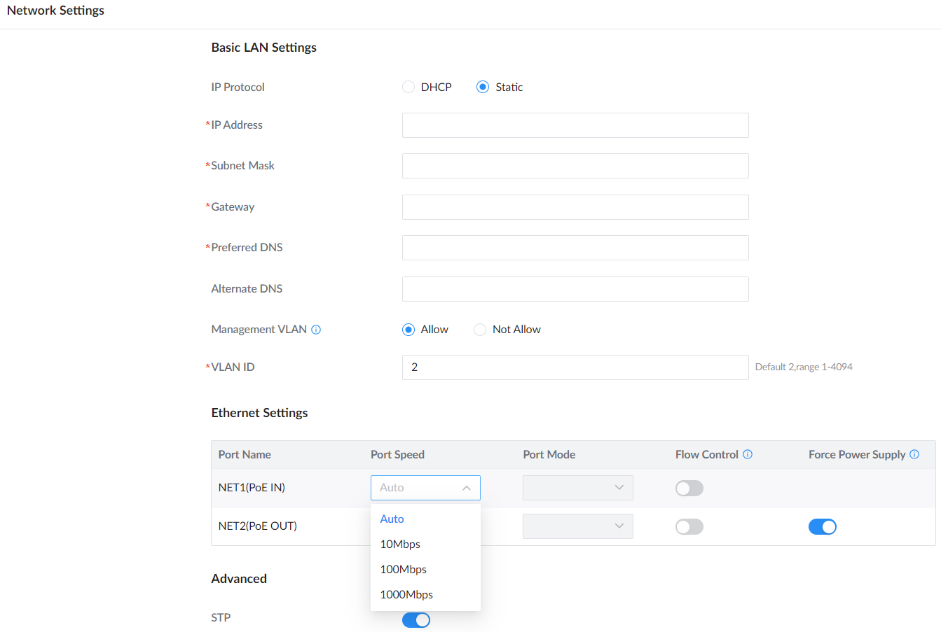
The Network Settings page on the GWN7302 controls how the device connects to the local network and passes data through its Ethernet ports. These settings apply to both Master and Slave units, and are critical for proper operation in PtP/PtMP mode.
Navigate to Web UI → Network Settings:
Basic LAN Settings
| Field | Description |
|---|---|
| IP Protocol | Choose between DHCP (default) or Static. Static IP is recommended in large networks to avoid IP conflicts or for static routing. |
| IP/Subnet/Gateway/DNS | Required only when Static is selected. These fields must be filled to ensure proper connectivity. |
| Management VLAN | Enables VLAN tagging for management traffic. Paired devices must be in the same management VLAN to prevent disconnection. When Allow is selected, you must also define a valid VLAN ID (1–4094). |
| VLAN ID | VLAN tag used for management access. Default is 2. Must match your switch/router configuration. |
Tip: VLAN support is useful when deploying the GWN7302 in segmented enterprise networks or when isolating management traffic.
Ethernet Port Configuration
Each port can be fine-tuned independently:
| Field | Description |
|---|---|
| Port Name | NET1 = PoE IN, NET2 = PoE OUT |
| Port Speed | Options: Auto, 10Mbps, 100Mbps, or 1000Mbps (default). |
| Port Mode | Full or Half Duplex. Full is recommended for all deployments. |
| Flow Control | Enables Ethernet flow control for congestion prevention. Disabled when Half Duplex is selected. |
| Force Power Supply | Controls PoE OUT (NET2) forced power output. • Disabled: PoE OUT supplies power only when the input power is DC or 802.3at. • Enabled: PoE OUT is forced to supply power; when the input power is 802.3af, PoE OUT power may be unstable due to the input power limit. |
Note: “When half-duplex mode is selected, traffic control does not take effect.”
Advanced
| Field | Description |
|---|---|
| STP | Enables or disables Spanning Tree Protocol. STP helps prevent network loops when the device is connected to a switching network. |
Once you’ve set the desired options, click Save at the bottom of the page.
Note: IP changes (especially switching from DHCP to Static) may cause a brief connectivity interruption.
Network Service
The Network Service section provides advanced management features for handling protocols and services such as multicast control, DDNS, SNMP, and remote provisioning.
Navigate to Web UI → Network Service:
Traffic Suppression
This page helps limit unwanted broadcast/multicast traffic from overwhelming the device or the wireless link. Enabling suppression can help maintain stable PtP/PtMP performance, especially in large Layer 2 networks.
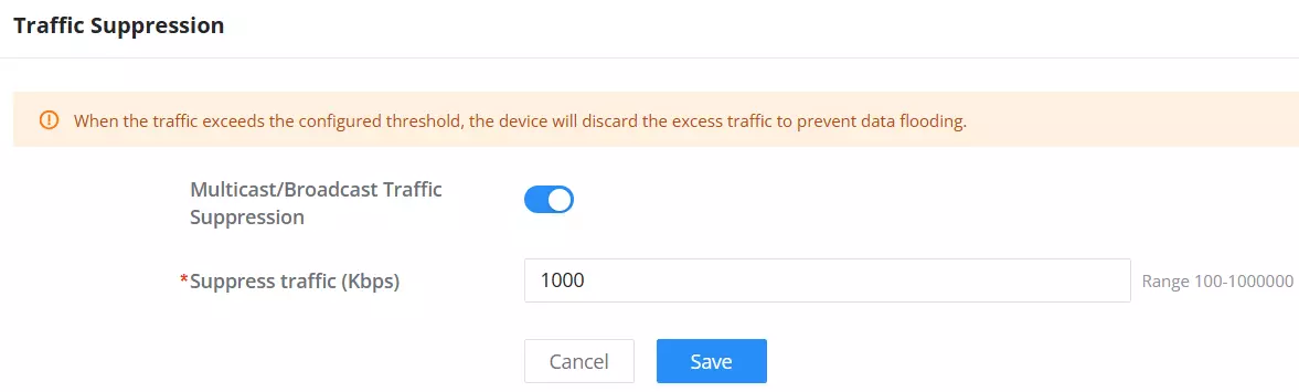
| Option | Description |
|---|---|
| Multicast/Broadcast Traffic Suppression | Toggle ON to enable suppression. When enabled, excess broadcast or multicast traffic will be discarded once it exceeds the configured threshold. |
| Suppress traffic (Kbps) | Set the maximum allowed rate (in Kbps). Any traffic beyond this limit is dropped. Range: 100 – 1,000,000 Kbps |
Warning Message: “When the traffic exceeds the configured threshold, the device will discard the excess traffic to prevent data flooding.”
Tip: This is useful when connecting the GWN7302 to networks with chatty devices or unmanaged switches that send unnecessary broadcast floods (e.g., IPTV, unmanaged camera systems).
DDNS
The DDNS page allows the GWN7302 to dynamically update a hostname record with its current IP address. This is essential for remote management over the internet when the WAN IP is dynamic (DHCP).
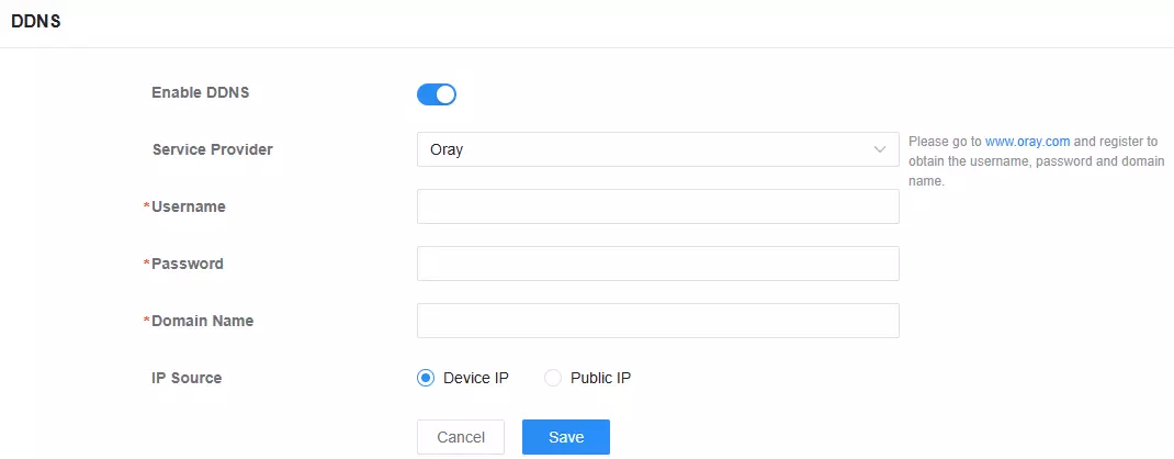
| Field | Description |
|---|---|
| Enable DDNS | Toggles DDNS functionality. Must be enabled to configure the options below. |
| Service Provider | Select from supported DDNS providers: Oray, Dyndns, or No IP. |
| Username / Password / Domain Name | Your DDNS account credentials and domain to link with the device. |
| IP Source | Choose whether the DDNS provider receives the device’s internal IP (Device IP) or its external/WAN IP (Public IP). |
Tip: Use Public IP for remote access scenarios (e.g., accessing the GWN7302 from the internet). Use Device IP only in VPN or internal deployments.
SNMP
The SNMP (Simple Network Management Protocol) page allows external network management systems to monitor and configure the GWN7302.
Supports both SNMPv1/v2c (community-based) and SNMPv3 (secure, user-based).
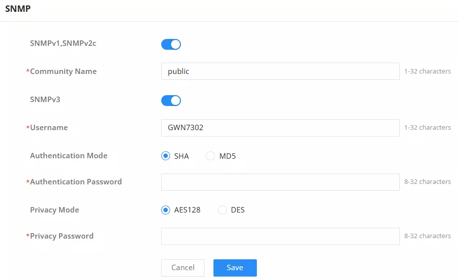
| Field | Description |
|---|---|
| SNMPv1, SNMPv2c | Toggle to enable legacy SNMP versions. |
| Community Name | Acts like a password for SNMPv1/v2c queries. Default is public. Allowed length: 1–32 characters. |
| SNMPv3 | Toggle to enable SNMPv3, which uses secure user-based access. |
| Username | SNMPv3 login username. Max 32 characters. |
| Authentication Mode | Choose SHA (recommended) or MD5. |
| Authentication Password | Password used with the selected authentication mode. Required, 8–32 characters. |
| Privacy Mode | Choose data encryption method: AES128 (recommended) or DES. |
| Privacy Password | Password for encrypting SNMPv3 payloads. Must be 8–32 characters. |
Tip: SNMPv3 is recommended for production deployments where secure communication is essential. SNMPv1/v2c may be used in simpler or legacy setups, but offer no encryption or strong authentication.
Note: If both SNMPv3 and v1/v2c are enabled, make sure the credentials used match what your external monitoring tool (e.g., Zabbix, PRTG, Nagios) supports.
TR069
TR-069 (CWMP) enables remote management and provisioning of the GWN7302 via an Auto Configuration Server (ACS). This is commonly used by service providers for large-scale deployments, monitoring, and firmware upgrades.
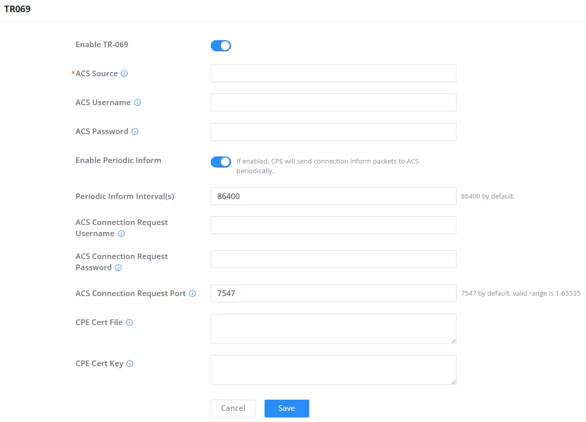
| Field | Description |
|---|---|
| Enable TR-069 | Frequency of inform packets (in seconds). The default is 86400 (i.e., once per day). |
ACS Source * | URL or IP address of the Auto Configuration Server (ACS). Required. |
| ACS Username / Password | Credentials used by the device to authenticate with the ACS server. |
| Enable Periodic Inform | If enabled, the device will send inform packets to the ACS at regular intervals. |
| Periodic Inform Interval(s) | Port for inbound ACS requests. The default is 7547, valid range: 1–65535. |
| ACS Connection Request Username / Password | Credentials the ACS uses to remotely trigger a session on the device. |
| ACS Connection Request Port | Port for inbound ACS requests. Default is 7547, valid range: 1–65535. |
| CPE Cert File / Cert Key | Upload client-side certificate files if mutual TLS authentication is required by the ACS. |
Tip: You must configure proper DNS, IP, and NAT/port forwarding on your router/firewall if using TR-069 across different networks or WAN interfaces.
Security Note: TR-069 introduces external control over the device, ensures strong credentials, enables TLS if supported, and locks ports when not in use.
System Settings
The System Settings section allows administrators to configure fundamental parameters related to the device’s operation, access control, maintenance, and system alerts. This includes defining the device name and regional settings, applying firmware updates, managing administrator accounts, scheduling maintenance tasks, and enabling alert notifications. These configurations ensure secure access, consistent time synchronization, and optimal long-term performance of the GWN7302 in various deployment environments.
Basic Settings
This section contains two tabs for core configuration and GWN Manager integration:
Basic Settings Tab
Used to configure the device’s identity, location/time details, and PtP/PtMP role.
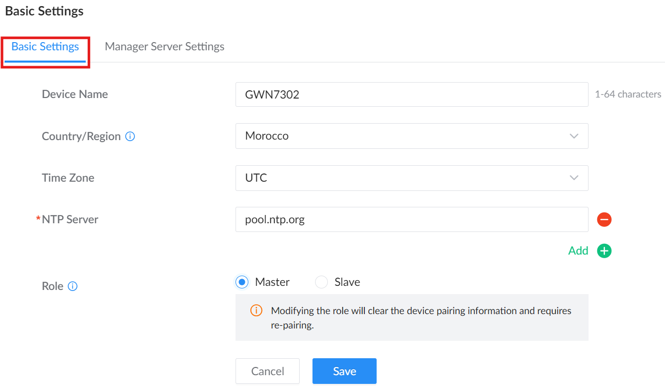
| Setting | Description |
|---|---|
| Device Name | Name shown in the Web UI and management platforms (1–64 characters). |
| Country/Region | Select the country/Region of deployment. Note: Modifying the country/region may reset the bandwidth, channel, and transmit power. Paired devices must be in the same country/region to prevent disconnection. |
| Time Zone | Choose the timezone for accurate logging and schedules. |
| NTP Server | Enter an NTP server (e.g., pool.ntp.org) to sync system time. Up to 4 NTP servers can be configured. |
| Role | Select the device role. Master transmits the bridge signal and typically connects to an uplink device such as a switch or router. Slave receives the bridge signal and extends the network to a remote site, typically connecting to terminal devices such as cameras. Note: Switching roles clears the pairing information and requires re-pairing. |
Manager Server Settings
Used to register the device with GWN Manager for centralized provisioning, firmware upgrades, and monitoring.
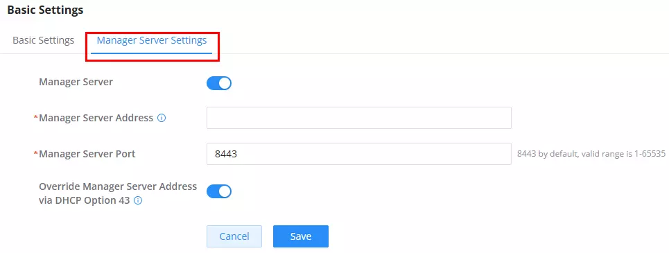
| Setting | Description |
|---|---|
| Manager Server | Toggle to enable GWN Manager connectivity. |
| Manager Server Address | Input the IP or domain name of the GWN Manager server. |
| Manager Server Port | Default is 8443. Valid range: 1–65535. |
| Override via DHCP Option 43 | When enabled, accepts a Manager address sent via DHCP. |
See also: GWN Manager Quick Installation Guide
Security Management
This section controls remote access methods and session security for the GWN7302. It includes encrypted web access, SSH login options, and passwordless authentication for remote management via GDMS.
Web Service
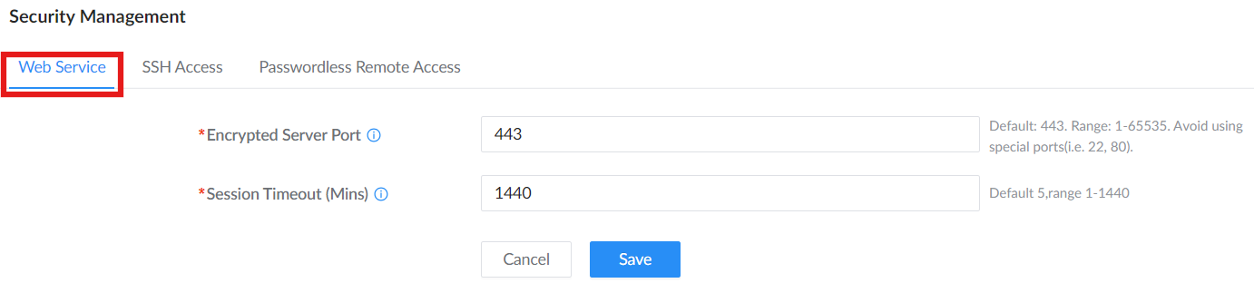
Configure web UI access parameters:
- Encrypted Server Port: Defines the HTTPS port used to access the device’s web interface. Default is
443. Valid range is1–65535. Avoid reserved ports like22or80.
Note: The device can be managed via the GWN App (Single Device) function only when this port is set to 443.
- Session Timeout (Mins): Sets how long the web UI session remains active without user activity. The default is 5 minutes. Range: 1–1440. Changes to this setting take effect after the user logs out and logs in again.
SSH Access
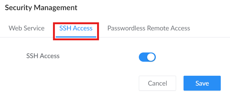
Allow secure CLI-based configuration and remote diagnostics via SSH.
Security Management → SSH Access This section allows you to enable SSH functionality for device-level access using the command-line interface (CLI).
Note: SSH Access is intended for advanced users or support engineers. For security reasons, it’s recommended to keep it disabled unless explicitly required.
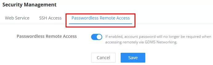
Passwordless Remote Access
When enabled, users can log in remotely via GDMS Networking without entering a password. This improves convenience but should be used with caution in sensitive deployments.
Upgrade
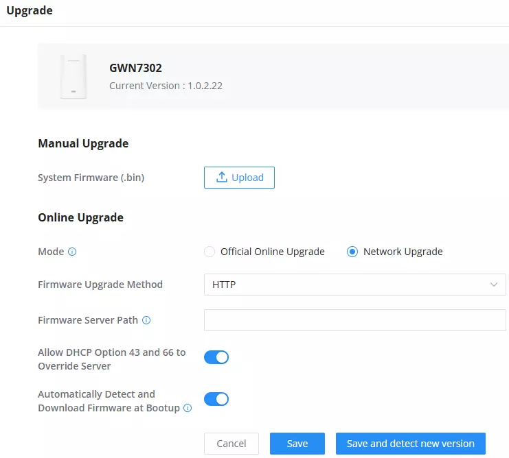
The Upgrade section provides administrators with two main methods to update the device firmware: Manual Upgrade and Online Upgrade. This functionality ensures that the GWN7302 stays up-to-date with the latest features, improvements, and security patches.
Manual Upgrade (Network Upgrade)
This method allows you to upload a local firmware .bin file directly from your computer.
- System Firmware (.bin): Click Upload to browse and select the firmware file. Use this method if you’ve downloaded the firmware package manually from the official Grandstream site.
- Network Upgrade: Lets the device pull firmware from a user-specified server (HTTP, HTTPS, or TFTP).
- Firmware Server Path: Input the IP address or URL of the remote firmware server.
Online Upgrade (Official Online Upgrade)
This method allows the device to fetch and install firmware from a remote server or official source.
- Mode: Official Online Upgrade: automatically detects the latest firmware version when connected to the Internet.
- Allow DHCP Option 43 and 66 to Override Server:
Enable this option to allow DHCP to dynamically assign a firmware server. - Automatically Detect and Download Firmware at Bootup:
When enabled, the device will auto-check, download, and install firmware during each reboot.
User Management
The User Management section allows administrators to manage access credentials for the device. It includes two tabs:
Administrator
Used to modify the admin credentials for accessing the device interface.
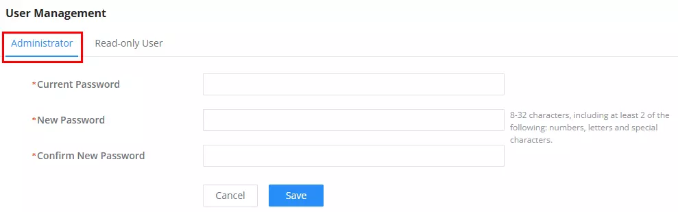
- Current Password: Enter the current admin password to authenticate the change.
- New Password: Set a new password for the admin account. It must be 8–32 characters long and include at least two of the following: letters, numbers, or special characters.
- Confirm New Password: Re-enter the new password to confirm.
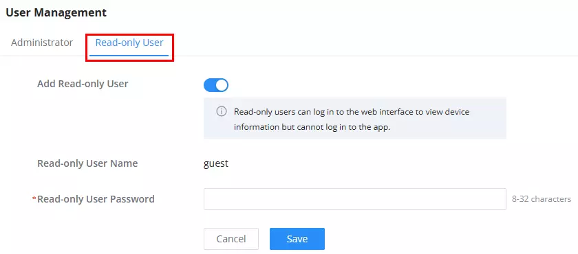
Read-only User
Allows creation of a limited-access user who can view but not configure device settings.
- Add Read-only User: Toggle to enable or disable read-only account creation.
- Read-only User Name: The Default is
guest(not editable). - Read-only User Password: Set a password (8–32 characters) for the guest user.
Note: Read-only users can access the Web UI to monitor device status, but cannot access the mobile app or modify configurations.
Maintenance
Basic Maintenance
The Maintenance section provides essential tools for managing the device’s operational state, diagnostics, backup/restore operations, and recovery procedures.
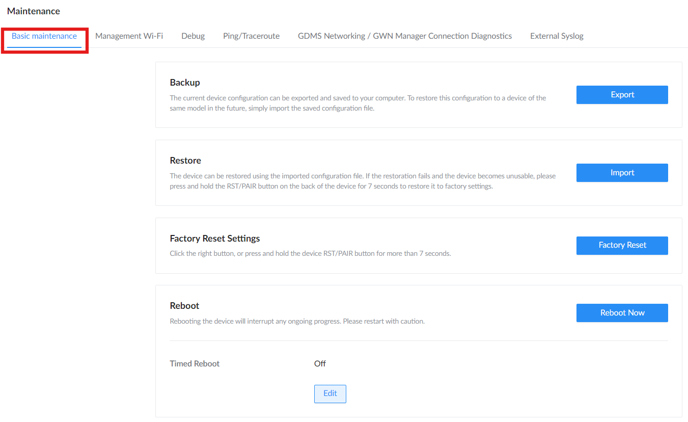
Backup
The Backup feature allows administrators to export the current device configuration to a local .bin file. This file can be saved and reused for future restoration or device duplication.
- Click Export to download the
.binfile. - The file is immediately saved to your computer; no additional confirmation is required.
Restore
The Restore option lets you import a previously saved .bin configuration file and apply it to the device.
- Click Import to browse and select the
.binfile from your system. - Upon confirmation, the device applies the configuration automatically.
- If the configuration becomes unusable, users can press and hold the RST/PAIR button on the device for 7 seconds to trigger a full factory reset.
Factory Reset Settings
Use this option to reset the device to its default factory configuration.
- Click Factory Reset to initiate the process.
- Alternatively, press and hold the physical RST/PAIR button for 7+ seconds.
Reboot
Used to manually or automatically reboot the device.
- Click Reboot Now to restart the device immediately. Rebooting may interrupt any active sessions.
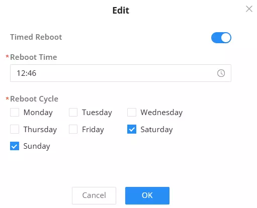
- Timed Reboot allows you to schedule automatic reboots at specific times:
- Click Edit to set the time and select the days of the week.
- Example: Schedule a reboot every Saturday and Sunday at 12:46 PM as shown.
Note: Use reboot scheduling cautiously to avoid interruptions during peak operation hours.
Management Wi-Fi
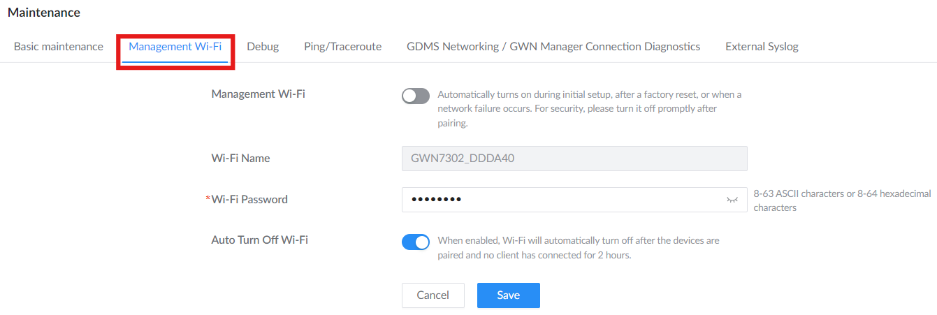
This Wi-Fi interface enables quick pairing and management during setup or network failure.
- Wi-Fi Name: Displays the Wi-Fi name.
- Auto Turn Off Wi-Fi: Toggles automatic shutdown after pairing.
- Wi-Fi Password: Can be viewed/edited for secure access.
Debug
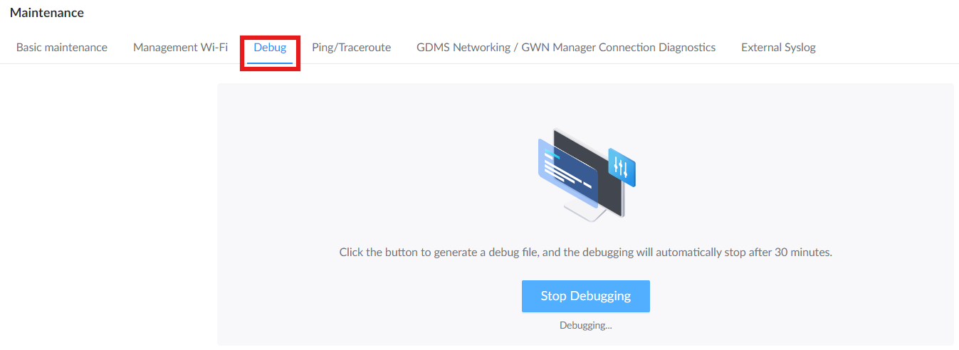
Used for troubleshooting by generating a debug file for support analysis.
- Click Start Debugging to initiate a session.
- Click Stop Debugging to end it manually.
- Sessions automatically stop after 30 minutes.
- Once generated, the debug file can be downloaded or deleted from the interface.
Ping/Traceroute
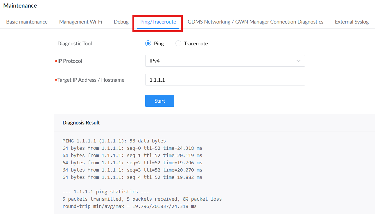
Use Ping/Traceroute to test network reachability and check the route path from the GWN7302 to another device or host.
Go to System Settings → Maintenance → Ping/Traceroute, then:
- Select the Diagnostic Tool:
• Ping: Tests whether the target IP address or hostname is reachable and displays packet loss and round-trip time.
• Traceroute: Shows the route path used to reach the target host. - Select the IP Protocol (IPv4 or IPv6).
- Enter the Target IP Address / Hostname.
- Click Start.
The output appears in Diagnosis Result. For Ping, the result shows replies, packet loss, and round-trip time. For Traceroute, the result shows the route path to the target host.
Note: If you ping a hostname and it fails but an IP address works, that usually means DNS is not reachable or not configured.
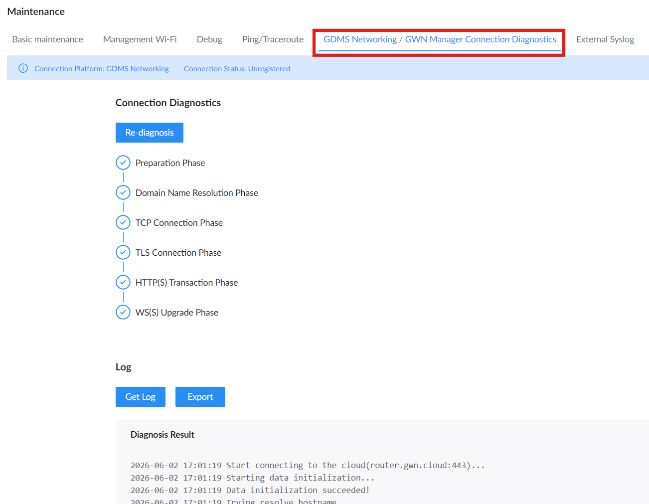
GDMS Networking / GWN Manager Connection Diagnostics
This section shows the current connection platform status (e.g., GDMS Networking) and the connection status (e.g., Registered or Unregistered).
Users can run a full cloud diagnostic process by clicking Re-diagnosis, which checks several phases, including DNS resolution, TCP/TLS connection, and cloud WS(S) upgrade. The log result is displayed below for real-time visibility.
You can also Get Log to view it live or Export it as a downloadable file for deeper analysis.
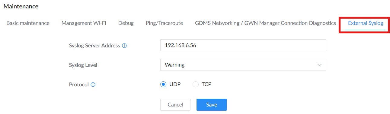
External Syslog
This section allows forwarding of system logs to a specified external syslog server.
Enter the IP address or URL of the server, select the log severity level (Emergency, Alert, Critical, Error, Warning, Notice, Information, or Debug), choose the desired protocol (UDP or TCP), then click Save.
Remote Support
When enabled, authorize Grandstream support engineers to temporarily access device diagnostic data, logs, and configuration information. This service is for troubleshooting and maintenance purposes only, and no personal information will be collected. All remote access sessions are fully encrypted, and this feature will be automatically disabled after 48 hours.
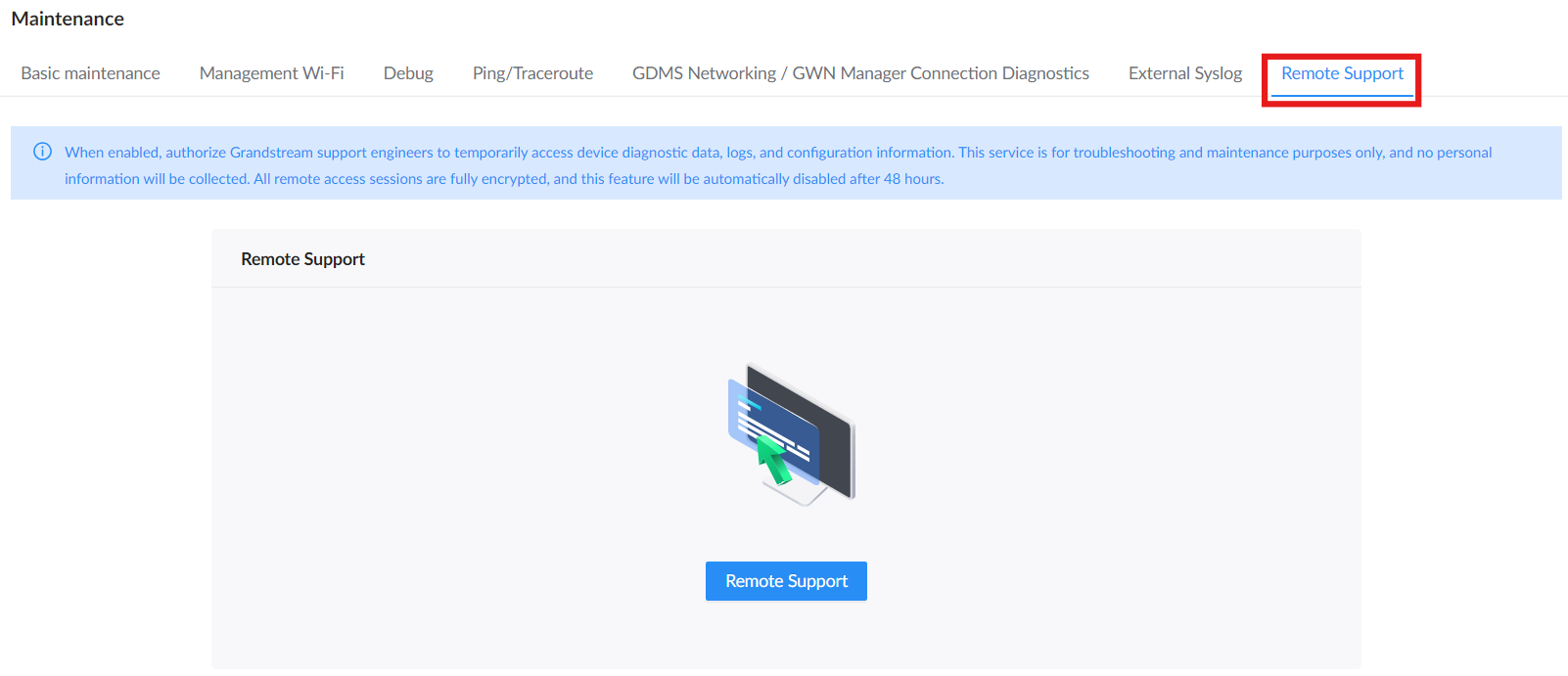
Steps to Enable Remote Support
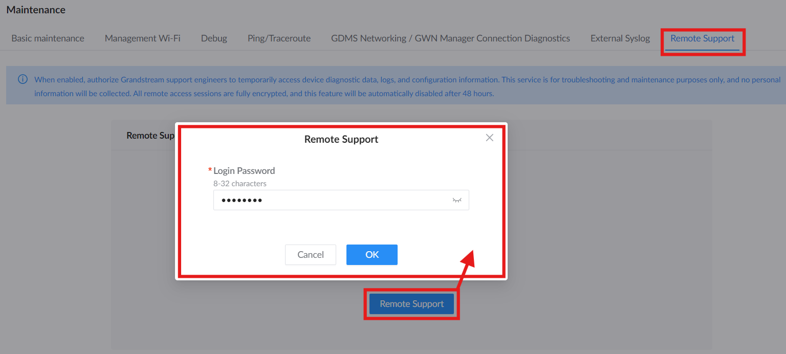
- Go to: System Settings → Maintenance → Remote Support.
- Click on the blue Remote Support button to initiate the session.
- A login window will appear, prompting for the login password. Input your admin credentials and click OK to continue.
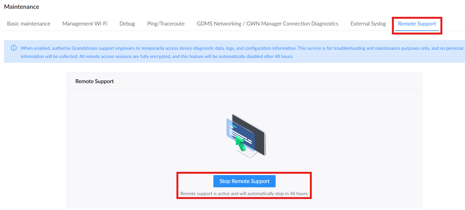
- Once validated, the system activates remote access. A confirmation message will appear below the button stating: “Remote support is active and will automatically stop in 48 hours.”
- At any time, you can manually terminate the session by clicking the Stop Remote Support button.
Important Notes:
- Remote Support is temporary and automatically expires after 48 hours.
- It cannot be activated without entering the admin password.
- This feature is exclusive to support and troubleshooting scenarios and should be used cautiously to minimize security risks.
Alerts
This section displays device alerts and allows users to configure email-based notifications for various alert types.
Alerts Tab
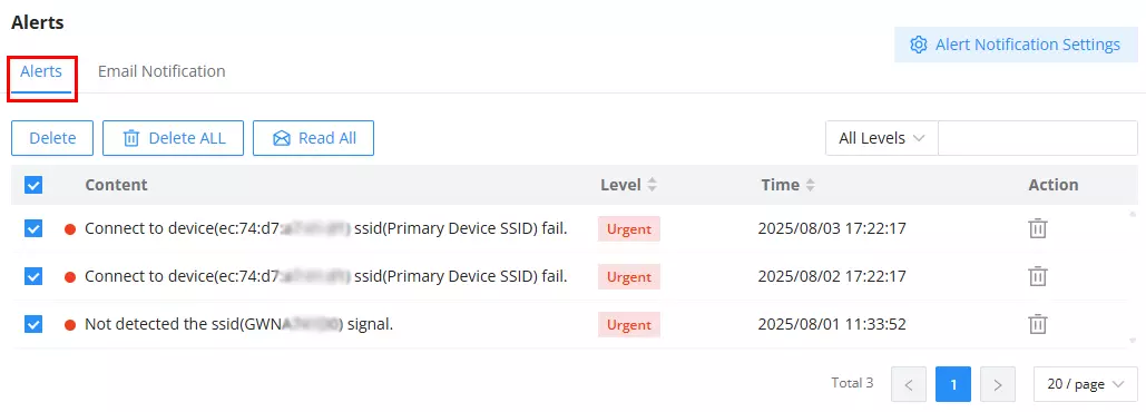
The Alerts tab lists all current and past system alerts, such as signal loss or failed SSID connections. Each entry includes:
- Content: Description of the alert (e.g., SSID not detected).
- Level: Severity of the alert (e.g., Urgent).
- Time: Timestamp when the alert was triggered.
- Action: Trash icon to delete individual alerts.
Users can:
- Delete one or all alerts.
- Mark all as read.
- Filter alerts by severity using the All Levels dropdown.
- Access the alert settings by clicking Alert Notification Settings in the top-right corner.
Email Notification
Enable this feature to receive alerts via email.
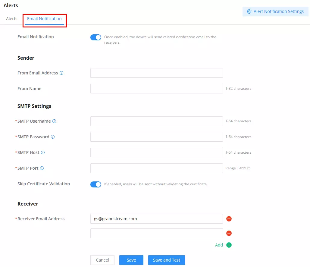
Email Notification toggle: Must be ON to activate alert emails.
Sender Configuration:
From Email Address: Email address the alert will be sent from.From Name: Display name for the sender.
SMTP Settings:
SMTP Username: Account used to authenticate the SMTP session.SMTP Password: Corresponding password for the SMTP account.SMTP Host: Outgoing mail server address (e.g., smtp.example.com).SMTP Port: Mail server port (default depends on encryption used).
Optionally, you can Skip Certificate Validation to send emails without SSL/TLS certificate checks.
Receiver(s):
Receiver Email Address: One or more recipients (e.g., it@company.com). Multiple can be added.
Alert Notification Settings
Accessed from the top-right of either tab, this section lets users fine-tune what events trigger alerts and which ones should also be emailed, like Wi-Fi Disconnected, PoE Alarm, Device Upgrade Failed, etc.
Note: For the PoE Alarm, when the temperature reaches 110°C, the PoE output power will decrease. When the temperature reaches 115°C, the PoE OUT function will be disabled. When the temperature returns to 100°C, the PoE OUT function will be restored.
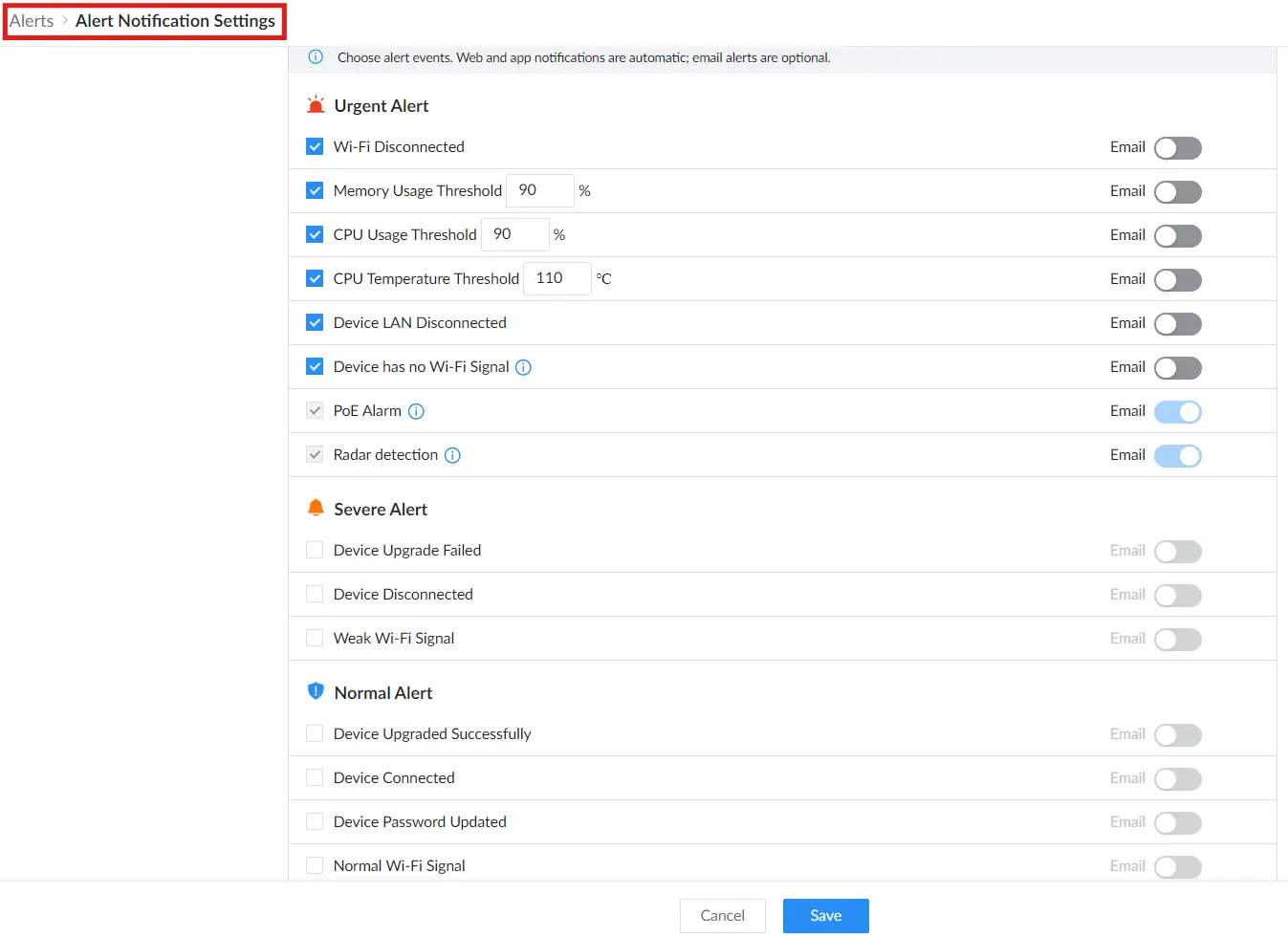
Alert Levels:
- Urgent Alerts: Critical conditions like Wi-Fi or LAN disconnects, or high CPU/memory/temperature thresholds.
- Severe Alerts: Upgrade failures or device disconnections.
- Normal Alerts: Device upgrades, connections, and password changes.
Each event can be toggled ON/OFF for web visibility, and optionally enable the Email toggle for remote notifications.
Operation Log
The Operation Log page records system and user actions performed on the device, such as login attempts, configuration changes, pairing actions, link tests, and spectrum analyzer operations.
Navigate to Web UI → System Settings → Operation Log.
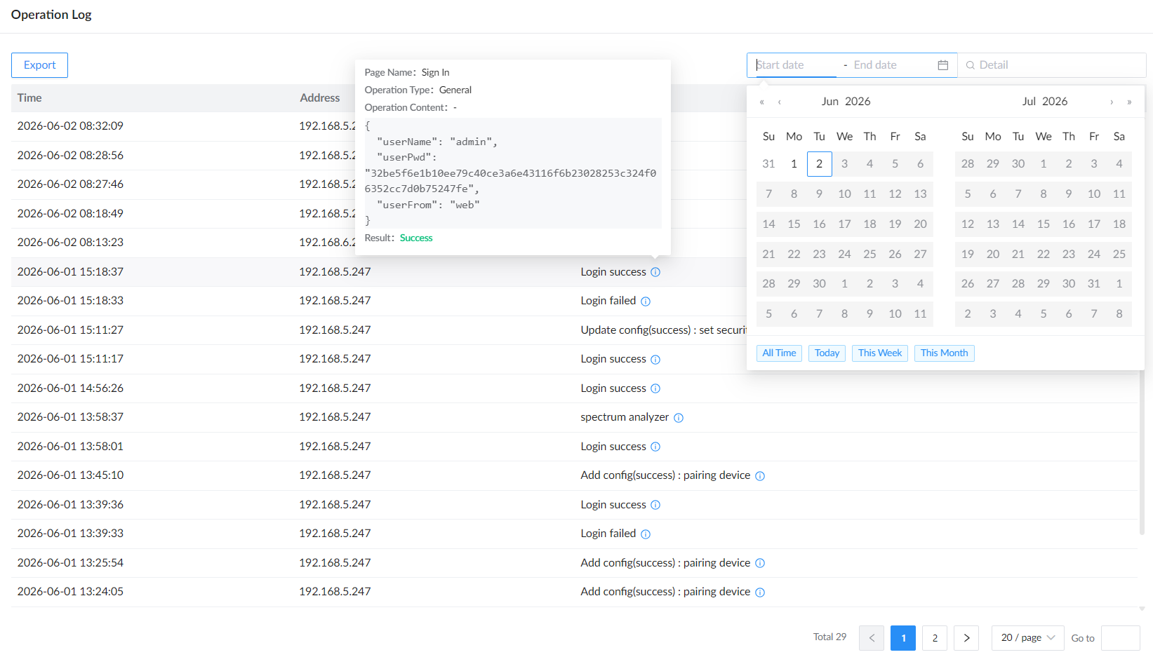
The operation log table displays each record with the following information:
| Field | Description |
|---|---|
| Time | Displays the date and time when the operation occurred. |
| Address | Displays the IP address of the client or device that performed the operation. |
| Detail | Displays a summary of the recorded operation, such as login success, login failed, link test, spectrum analyzer, or configuration update. |
Use the date filter to display logs within a selected time range. The available quick filters include All Time, Today, This Week, and This Month.
Use the Detail search box to search for specific operation records.
Click the information icon next to a log detail to view more information about that operation, including the page name, operation type, operation content, and result.
Click Export to download the operation log as a CSV file.
Tools
Link Test
The Link Test measures throughput between the two devices.
Who Does What?
- Either device can be Server or Client, but recommended:
- Master (Site A) → Server (easier to leave running).
- Slave (Site B) → Client (initiates the test).
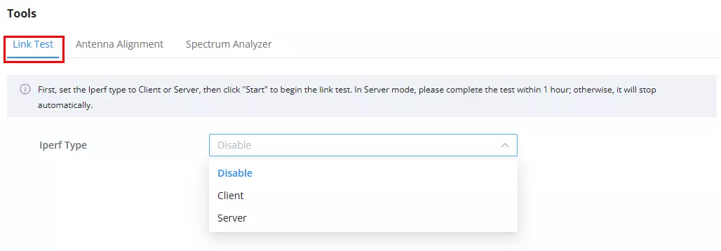
Note: Running the link test will temporarily affect the wireless transmission rate. A confirmation message will appear before proceeding.
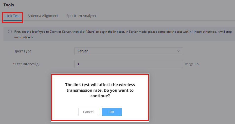
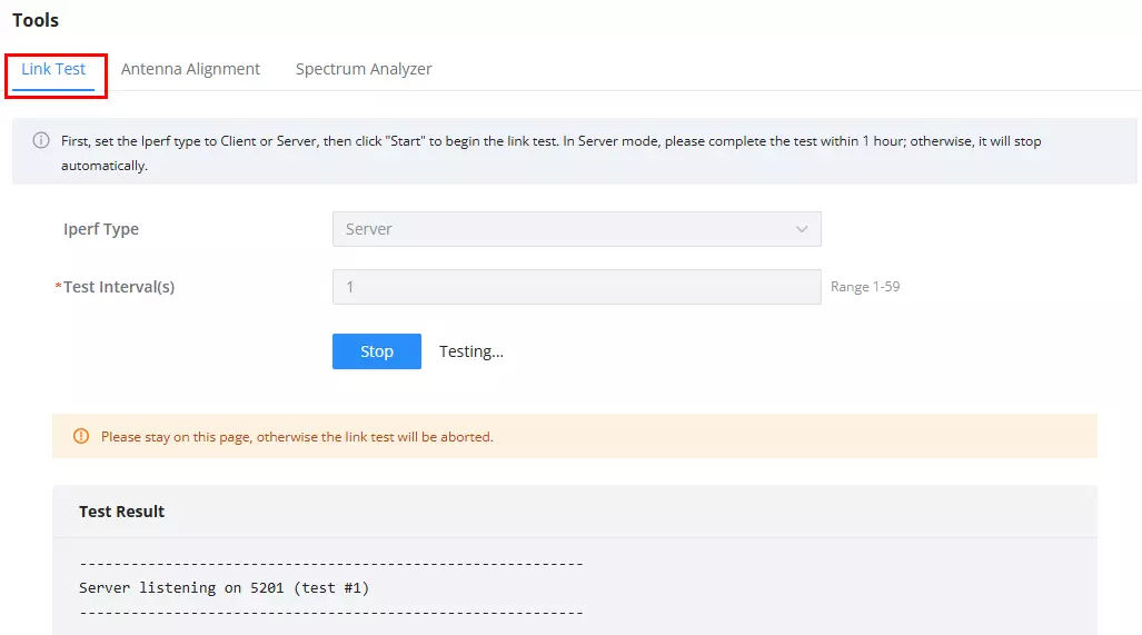
On Master (Server):
- Go to Web UI → Tools → Link Test.
- Select iPerf Type = Server and click Start.
- Leave it running (listening).
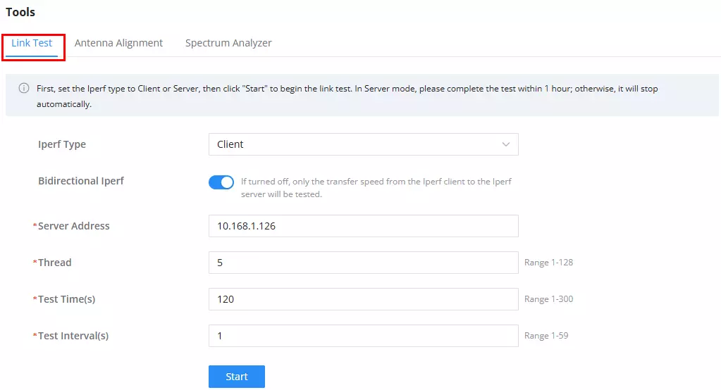
On Slave (Client):
- Go to Web UI → Tools → Link Test.
- Select iPerf Type = Client.
- Enter the Server’s IP address (auto-filled in most cases).
- (Optional) Enable Bidirectional iPerf to test both directions.
- Click Start to begin.
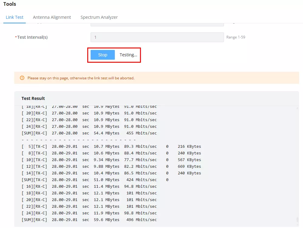
Review Results:
- Throughput and stability will appear under Test Result.
- Stop manually when finished.
Antenna Alignment
The user can fine-tune the link quality using either method:
a) Using Web UI – Antenna Alignment Tool
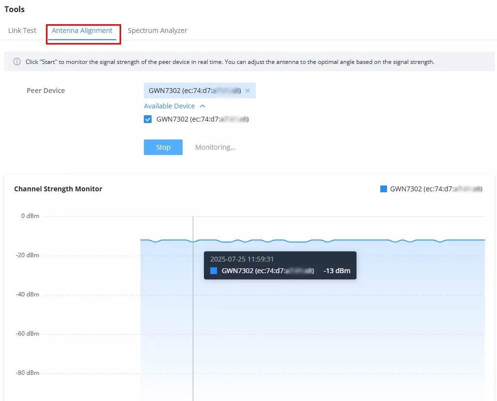
- Go to Web UI → Tools → Antenna Alignment.
- Select the paired device from the list.
- Click Start to monitor real-time signal strength.
- Adjust the antenna angle until the graph shows the strongest (highest) dBm value.
b) Using Device LEDs
- Check the 3 Signal LEDs on the side of the unit.
- Rotate or tilt the device slowly until you reach 3 solid green bars for optimal signal.
For complete pairing and alignment instructions, refer to the GWN7302 Pairing Guide.
Spectrum Analyzer
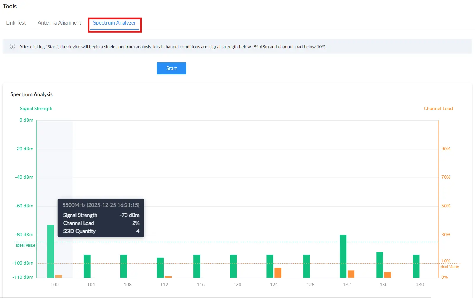
The Spectrum Analyzer runs a single scan of nearby 5 GHz channels to help you pick a cleaner channel (less interference).
How it works: Click Start to run one spectrum analysis.
To scan again, click again
How to read the results:
- Signal Strength (green bars): lower (closer to -85 dBm) is better (less interference).
- Channel Load (orange bars): lower is better, ideally below 10%.
- SSID Quantity: Fewer SSIDs usually mean a cleaner channel.
- Hover a bar to see channel details (timestamp, signal strength, channel load, SSID quantity).
Steps:
- Go to Web UI → Tools → Spectrum Analyzer.
- Click Start to run a single scan.
- Review the chart and pick a channel with low load and better signal conditions.
- If you change settings and want fresh results, click Start again.
Tip: Ideal conditions are Signal Strength below -85 dBm and Channel Load below 10% (these thresholds are shown on the chart).
Change Log
This section documents significant changes from previous versions of the GWN73xx user manuals. Only major new features or major document updates are listed here. Minor updates for corrections or editing are not documented here.
Firmware Version 1.0.5.4
- Added online and offline status indicators for paired slave devices in the topology diagram. [Overview]
- Added Historical Monitoring charts for throughput, negotiated rate, and signal strength. [Overview]
- Optimized device pairing guidance with wired pairing, device takeover, and a link to the dedicated Pairing Guide. [Device Pairing]
- Added STP option. [Network Settings]
- Added Operation Log page for viewing, filtering, and exporting device operation records. [Operation Log]
- Added Traceroute support to the Ping diagnostic tool for route tracking. [Ping/Traceroute]
- Updated the Maintenance page tab layout. [Maintenance]
- Added support for configuring up to 4 NTP servers. [Basic Settings]
- Added RF Settings note reminding users to keep the SSID, password, and encryption method consistent across paired devices. [RF Settings]
Firmware Version 1.0.3.28
- No major changes.
Firmware Version 1.0.3.22
- No major changes.
Firmware Version 1.0.3.17
- This is the initial release.