


Introduction
The GWN7660ELR is an enterprise-grade long-range Wi-Fi 6 access point that allows businesses to build next-generation Wi-Fi networks for high-density environments. It supports weatherproof casing and heat resistant technology, dual-band 2×2:2 MIMO with OFDMA technology, and a sophisticated antenna design for maximum network throughput that supports 256 clients and an expanded 300-meter coverage range. It also provides IP67 weatherproof and dust-proof ability, as well as -30 to 60°C operating temperature, this ensures that the Wi-Fi 6 access point can operate properly in difficult weather conditions. To ensure easy installation and management, the GWN7660ELR includes a built-in controller embedded within the product’s web user interface. It is also supported by GDMS Networking and GWN Manager, Grandstream’s free cloud and on-premise Wi-Fi management platform. The GWN7660ELR is the ideal Wi-Fi AP for voice-over-Wi-Fi deployment and offers a seamless connection with Grandstream’s Wi-Fi voice and video IP phones. With support for advanced QoS, low-latency real-time applications, mesh networks, captive portals, Bluetooth® Low Energy (BLE) 5.2, a gigabit Ethernet port with PoE/PoE+, and a 2.5 Gigabit SFP port. The GWN7660ELR is an ideal outdoor Wi-Fi access point for enterprises, multiple-floor offices, warehouses, hospitals, schools, and more.
This datasheet presents the antenna radiation patterns of the GWN7660ELR long-range access point model, for both the 2.4GHz and 5GHz bands, in addition to some other information and specifications about the interfaces of the device.
Specifications and Interface
Frequency(MHz) | 2.4G:2400~2500 | 5G:5150~5850 |
VSWR | ≦2.0:1 | |
Peak Gain(dBi) | 2G1:6.44 / 2G2:6.63 | 5G1:7.16 / 5G2:7.14 |
Efficiency(%) | 2.4G:≧75 | 5G:≧70 |
Isolation | ≦-15dB | |
Type | PCB Antenna | |
Radiation Properties | Omni-directional | |
Impedance(Ohms) | 50 | |
ROHS Compliant | Yes | |
Terminology
In this first part, we will provide a quick brief review of some fundamental concepts related to antennas and radio propagation:
- Antenna: An antenna is a transducer between a feed signal and a radiated wave over space, it is usually attached to a transmitter/receiver unit, and the radiated energy is characterized by the antenna’s radiation pattern.
- Antenna pattern: The radiation pattern or antenna pattern is the graphical representation of the radiation properties of the antenna and how it radiates energy out into space or how it receives energy (reciprocity). An antenna radiates energy in all directions, at least to some extent, so the antenna pattern is three-dimensional. It is common, however, to describe this 3D pattern with planar patterns called the principal plane patterns. These principal plane plots are commonly referred to as antenna radiation patterns.
- Isotropic radiator: An isotropic radiator is a hypothetical lossless antenna that radiates its energy equally in all directions. This imaginary antenna would have a spherical radiation pattern and the principal plane cuts would both be circles since any plane cut through a sphere would be a circle.
- Gain: The gain of an antenna (in a given direction) is defined as the ratio of the power gain in that direction to the power gain of a reference antenna in the same direction, usually, an isotropic radiator is set as the reference and the value of the gain is expressed in dBi. It is important to state that an antenna with gain doesn’t generate power and it does simply direct the way the radiated power is distributed relative to radiating the power equally in all directions, thus the gain is just a characterization of the way the power is radiated.
- Efficiency: The efficiency of an antenna is the ratio of the power delivered to the antenna relative to the power radiated from the antenna. A high-efficiency antenna has most of the power present at the antenna’s input radiated away. A low-efficiency antenna has most of the power absorbed as losses within the antenna or reflected away due to impedance mismatch Which causes an antenna to not have an efficiency of 100%.
- Antenna efficiency losses are typically due to:
- Conduction losses (due to finite conductivity of the metal that forms the antenna).
- Dielectric losses (due to conductivity of a dielectric material near an antenna).
- Impedance mismatch loss.
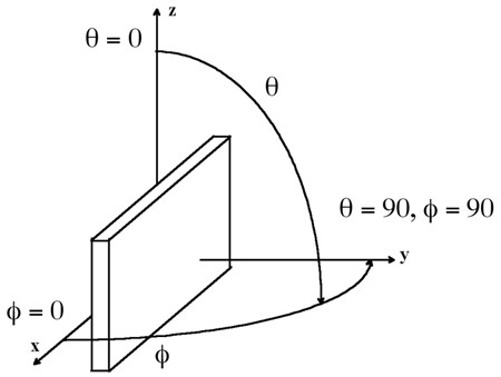
Test environment
This test report gives schematic diagrams with the antenna distribution of the GWN76xx access points series, along with the antenna radiation patterns of both 2.4Ghz and 5Ghz frequencies to help engineers during the deployment process.
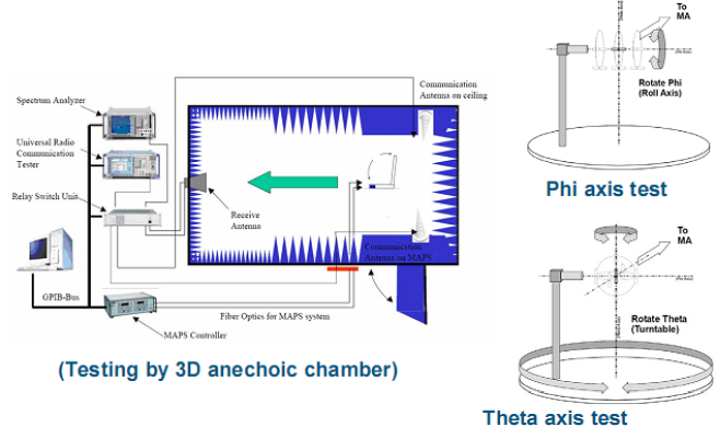
Please note that these radiation patterns are gathered in a fully anechoic environment. Their shape will change in installed environments depending on the obstacles that the wireless signal might face. Every deployment will behave differently due to materials, geometries of structures, etc, and how these materials behave at 2.4GHz and 5GHz.
The below figure gives an overview of the used test environment:
Antenna Radiation Patterns
Axis | 2.4G | 5G |
XZ | 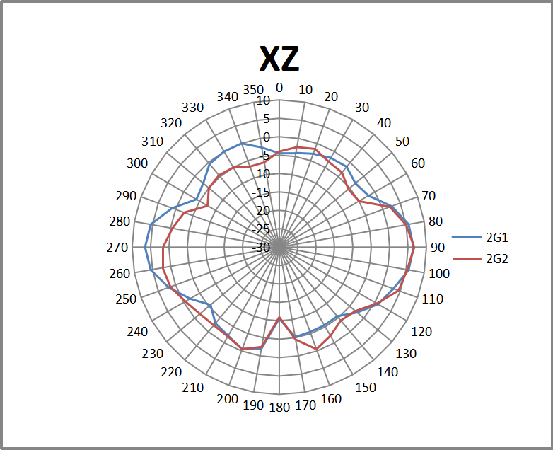 | 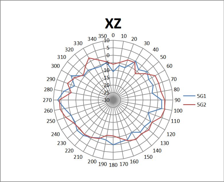 |
YZ | 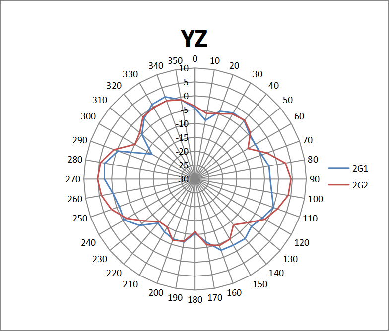 | 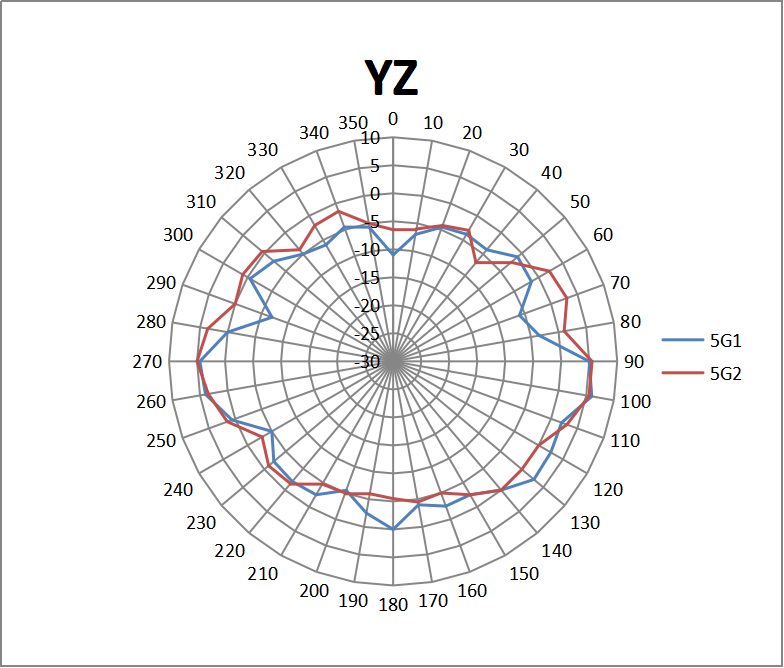 |
XY | 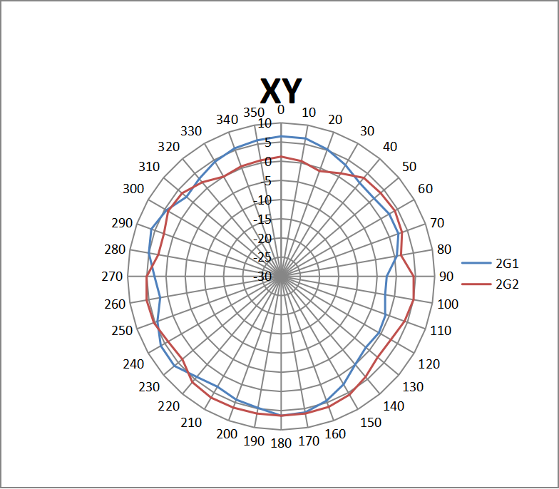 | 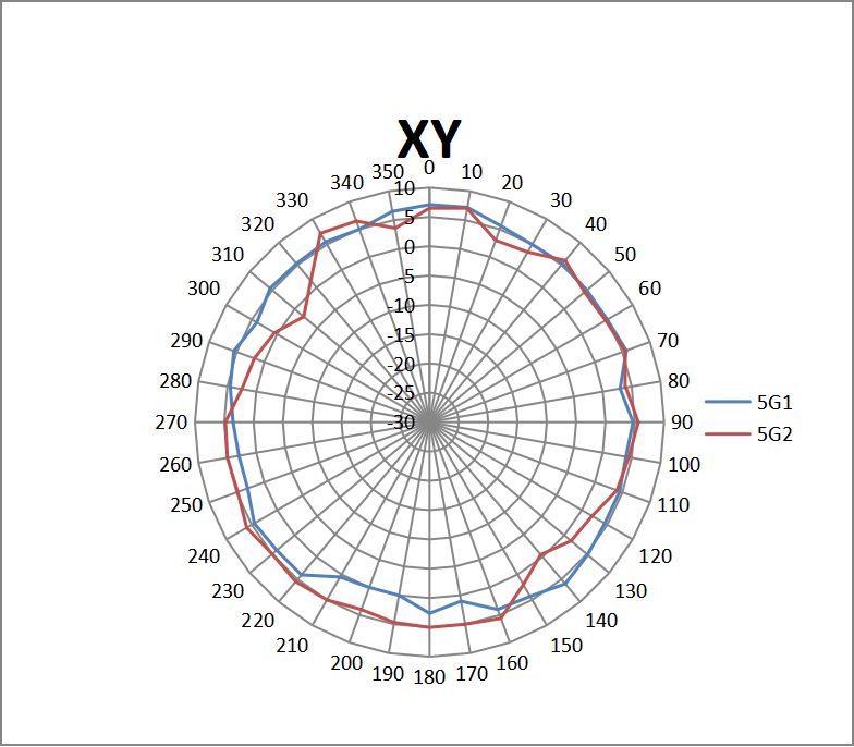 |
Antenna Radiation Patterns