


INTRODUCTION
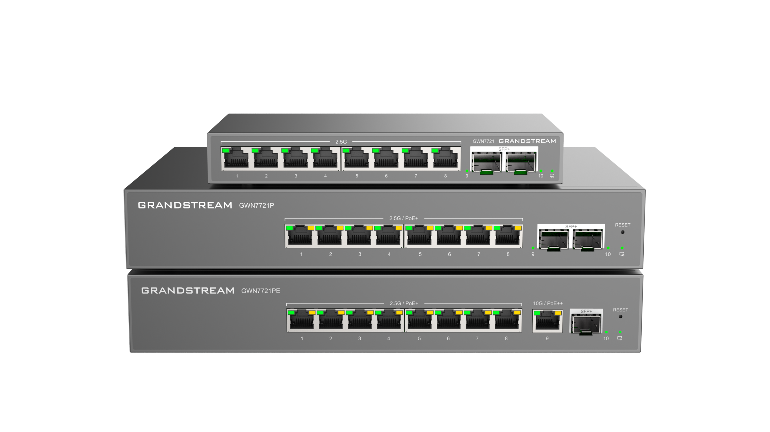
The GWN7721 Series consists of the GWN7721, GWN7721P, and GWN7721PE Layer 2 Lite managed multi-gigabit switches for scalable, secure, and intelligent small-to-medium business networks. The GWN7721 and GWN7721P provide eight 2.5 Gigabit Ethernet ports and two 10 Gigabit SFP+ ports. The GWN7721PE provides eight 2.5 Gigabit PoE/PoE+ Ethernet ports, one 10 Gigabit PoE/PoE+/PoE++ Ethernet port, and one 10 Gigabit SFP+ port. The series supports VLAN traffic segmentation, DSCP/802.1p QoS, bandwidth control, IGMP Snooping, and comprehensive security protection.
The GWN7721 Series is managed through the same local web user interface, GWN Manager, and Grandstream Device Management System (GDMS). Installation options depend on the model: the GWN7721 supports desktop or wall mounting, the GWN7721P supports desktop, wall, or rack mounting, and the GWN7721PE supports desktop or rack mounting.
PRODUCT OVERVIEW
Feature Highlights
- GWN7721
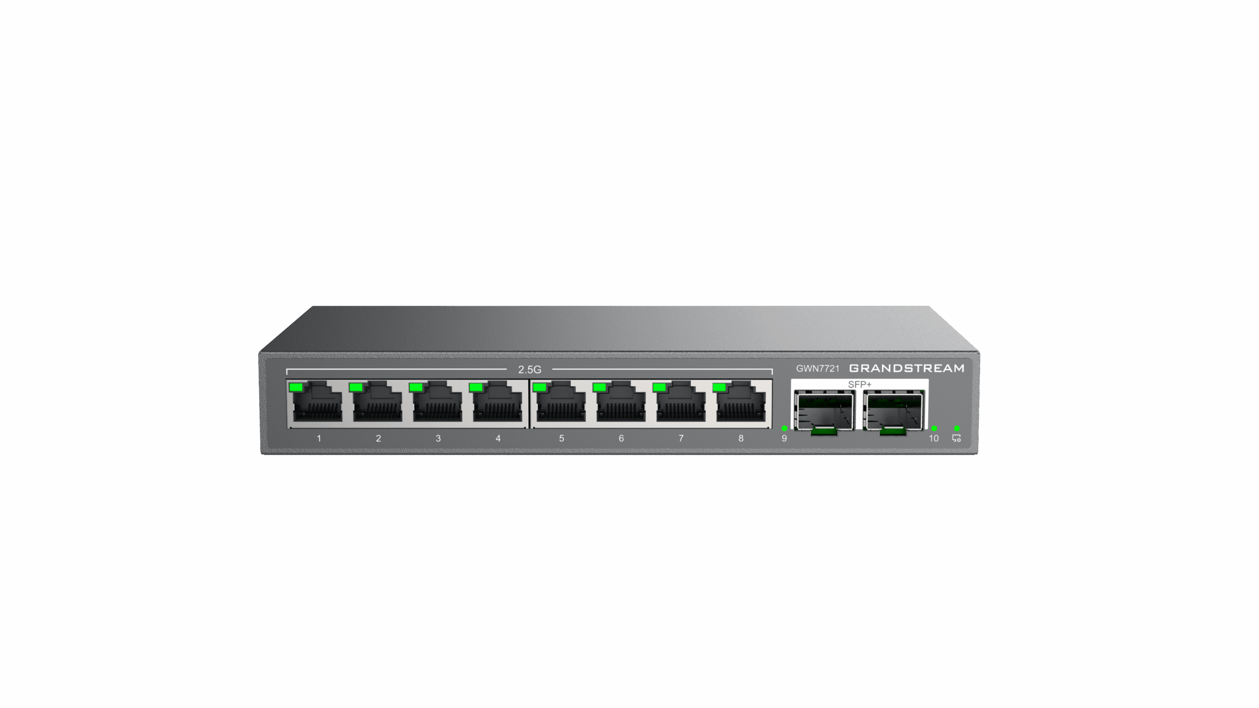 GWN7721 |
|
GWN7721 Features at a glance
- GWN7721P
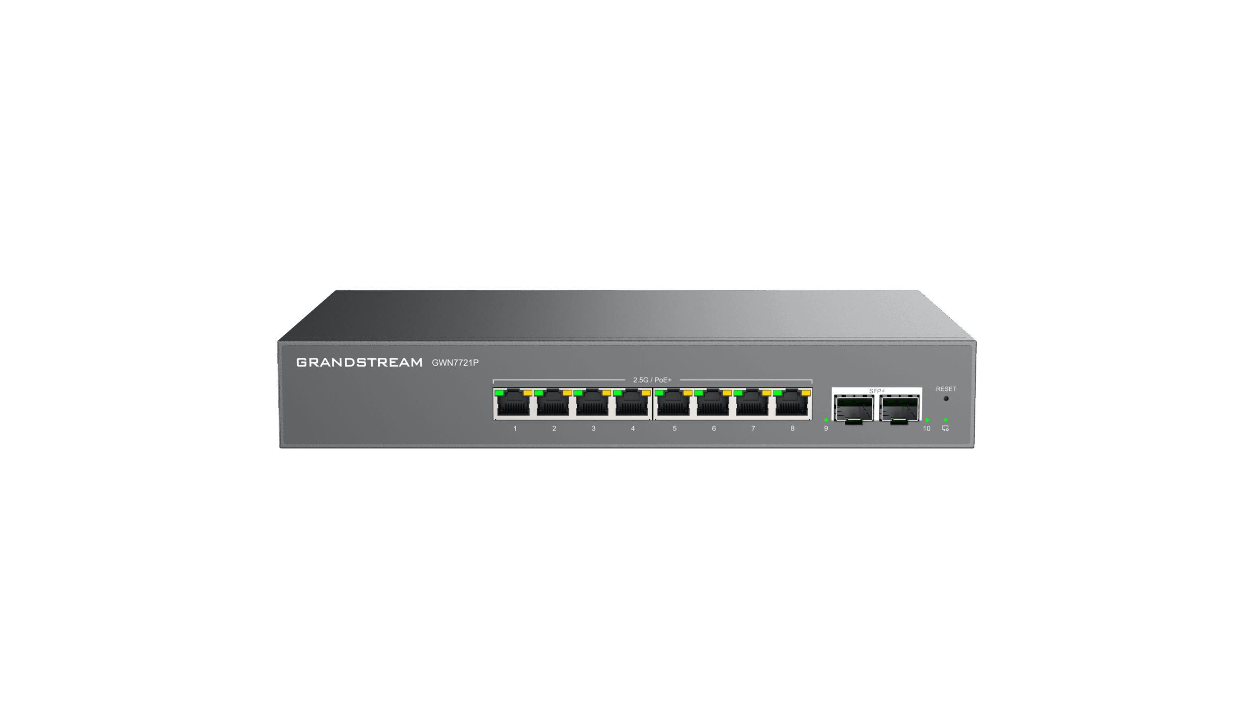 GWN7721P |
|
GWN7721P Features at a glance
- GWN7721PE
 GWN7721PE |
|
GWN7721PE Features at a glance
GWN7721 Series Technical Specifications
| GWN7721 | GWN7721P | GWN7721PE | |
|---|---|---|---|
| 2.5 Gigabit Ethernet ports | 8 | 8 | 8 |
| 10 Gigabit Ethernet ports | — | — | 1 |
| 10 Gigabit SFP+ ports | 2 | 2 | 1 |
| Maximum supported 10G modules | SM-10G: 2; MM-10G: 2; RJ45-10G: 1 | SM-10G: 2; MM-10G: 2; RJ45-10G: 1 | SM-10G: 1; MM-10G: 1; RJ45-10G: 1 |
| PoE standards | — | IEEE 802.3af/at | IEEE 802.3af/at/bt |
| PoE ports | — | 8 | 9 |
| Maximum output per PoE port | — | 30 W | 30 W (ports 1–8); 90 W (port 9) |
| Maximum total PoE output | — | 130 W | 130 W |
| Power supply | 12 V DC / 1 A | 100–240 V AC, 50/60 Hz | 100–240 V AC, 50/60 Hz |
| Total non-blocking throughput | 40 Gbps | 40 Gbps | 40 Gbps |
| Switching capability | 80 Gbps | 80 Gbps | 80 Gbps |
| Packet buffer | 8 Mb | 8 Mb | 8 Mb |
| MAC address capacity | 16K | 16K | 16K |
| Installation | Desktop or wall mount | Desktop, wall mount, or rack mount | Desktop or rack mount |
| Unit dimensions (L × W × H) | 190 × 100 × 28 mm | 280 × 180 × 44 mm | 280 × 180 × 44 mm |
| Package dimensions | 300 × 129.5 × 53 mm | 361 × 195.5 × 52 mm | 361 × 195.5 × 52 mm |
| Unit weight | 0.6 kg | 1.58 kg | 1.848 kg |
| Package weight | 0.767 kg | 2.036 kg | 2.088 kg |
| Data-transfer LEDs | 10 green LEDs | 10 green LEDs | 10 green LEDs |
| PoE supply LEDs | — | 8 yellow LEDs | 9 yellow LEDs |
| Operating temperature | 0 °C to 45 °C | 0 °C to 45 °C | 0 °C to 45 °C |
| Storage temperature | −20 °C to 60 °C | −20 °C to 60 °C | −20 °C to 60 °C |
| Humidity | 10%–90% RH, non-condensing | 10%–90% RH, non-condensing | 10%–90% RH, non-condensing |
| Surge protection | ±1 kV CM/DM (power); 1 kV (network ports) | ±6 kV CM/DM (power); ±2 kV (network ports) | ±6 kV CM/DM (power); ±2 kV (network ports) |
| ESD | ±12 kV contact discharge | ±12 kV contact discharge | ±12 kV contact discharge |
| Compliance | FCC, CE, RCM, IC | FCC, CE, RCM, IC | FCC, CE, RCM, IC |
INSTALLATION
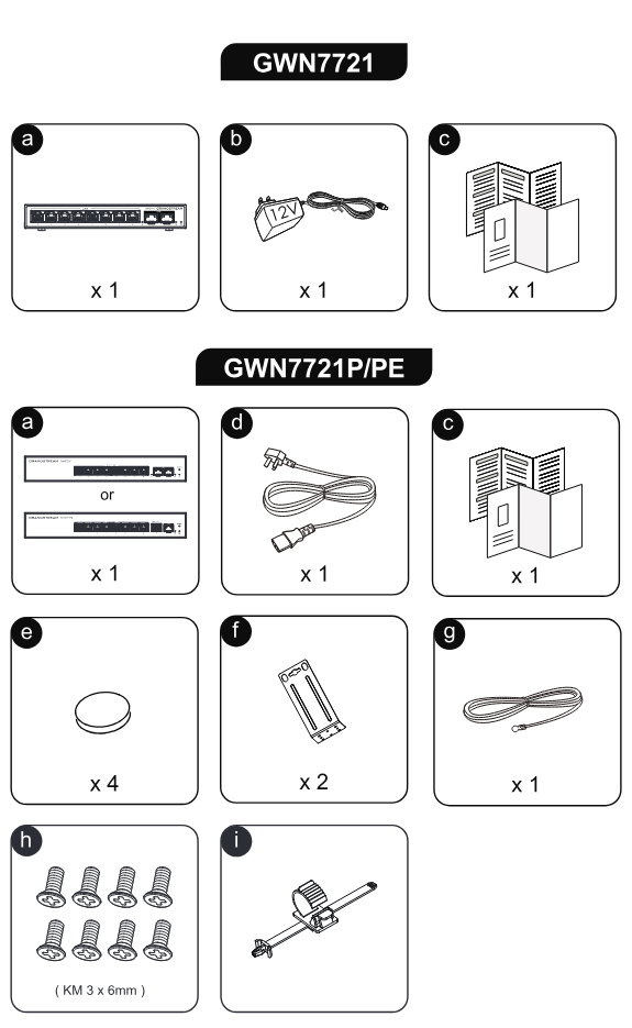
Before deploying and configuring the GWN772x switch, the device needs to be properly powered up and connected to the network. This section describes detailed information on the installation, connection, and warranty policy of the GWN772x switch.
Package Contents
- GWN7721 Series
Port Description
- GWN7721 Series
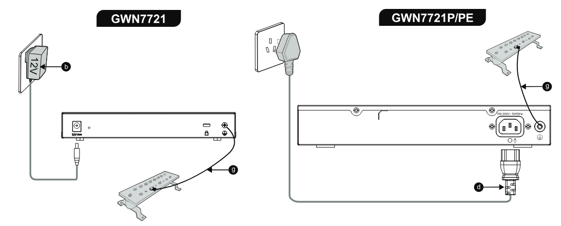
Grounding and Accessing GWN772x
Grounding the GWN7721 Series Switches
- Remove the ground screw from the back of the switch, and connect one end of the ground cable to the wiring terminal of the switch.
- Put the ground screw back into the screw hole, and tighten it with a screwdriver.
- Connect the other end of the ground cable to the other device that has been grounded or directly to the terminal of the ground bar in the equipment room.
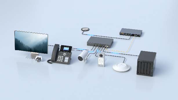
GWN7721P/PE Deployment Cases
802.3af/at PoE+ Power and Data Transmission
On the GWN7721P, ports 1–8 support IEEE 802.3af/at PoE/PoE+ with up to 30 W per port. On the GWN7721PE, ports 1–8 support up to 30 W per port and port 9 is a 10 Gigabit Ethernet port supporting IEEE 802.3af/at/bt PoE/PoE+/PoE++ with up to 90 W. The GWN7721P provides two 10 Gigabit SFP+ ports, while the GWN7721PE provides one 10 Gigabit SFP+ port.
- Port 1: 2.5G Gaming PC
- Port 3: 802.3af/at PoE+ GRP VoIP Phone
- Port 5: 802.3af/at PoE Camera
- Port 6: 802.3af PoE IP Video Intercom System
- Port 8: Wireless 802.3af PoE WiFi 6/6E AP
- GWN7721P ports 9–10: 10 Gigabit SFP+ uplinks.
- GWN7721PE port 9: 10 Gigabit RJ45 PoE++ port (up to 90 W); port 10: 10 Gigabit SFP+ uplink.
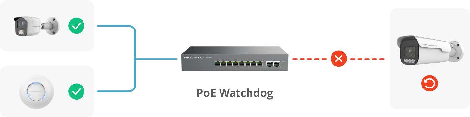
PoE Watchdog
Use VLAN to isolate the IP Camera/Internet/IPTV traffic. Use link aggregation to increase upstream bandwidth.
Anomaly Detection: The PoE switch continuously monitors the network operation status of connected powered devices (such as cameras, APs, IP phones, etc.).
Automatic Restart: If a device fails to respond within the set time, PoE Watchdog will proactively cut off its power supply and reboot it to restore functionality.
Reduced Manual Intervention: Eliminates the need for manual power plugging/unplugging or on-site maintenance, enhancing network reliability
GETTING STARTED
Device LED Indicators
The front panel of the GWN772x has LED indicators for power and interface activities. The table below describes the LED indicators’ status.
| LED indicator | Status | Description |
|---|---|---|
| System indicator | Off / green / blue / red | Power, upgrade, normal use, provisioning, failure, and factory-reset status |
| Port indicator | Off / green on / green flashing | No link, active link, or data transfer |
| PoE supply LED (GWN7721P) | 8 yellow LEDs | PoE status for ports 1–8 |
| PoE supply LED (GWN7721PE) | 9 yellow LEDs | PoE status for ports 1–9 |
Access and configure
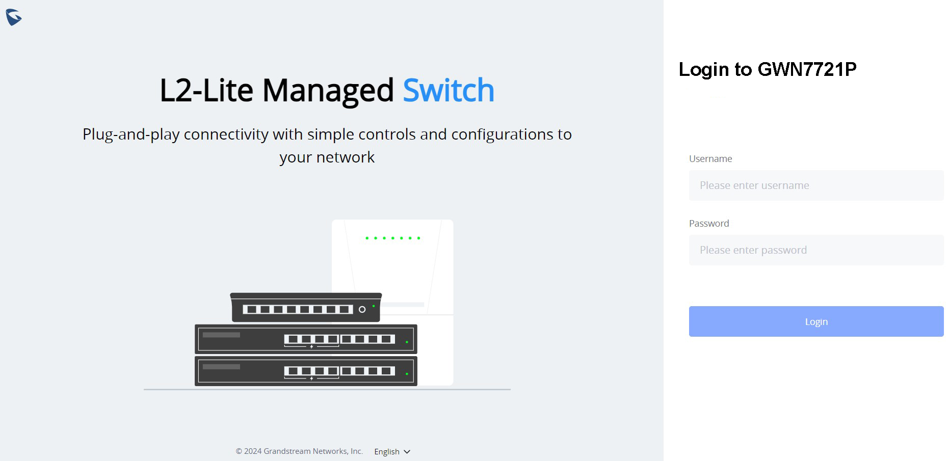
Log in using the Web UI
- A PC uses a network cable to correctly connect any RJ45 port of the switch.
- Set the Ethernet (or local connection) IP address of the PC to 192.168.0.x (“x” is any value between 1-253), and the subnet mask to 255.255.255.0, so that it is in the same network segment as the switch IP address. If DHCP is used, this step could be skipped.
- Type the switch’s management IP address http:// in the browser, and enter the username and password to log in. (The default administrator username is “admin” and the default random password can be found on the sticker on the GWN772x switch.)
Configure using GDMS Networking/GWN Manager
Type https://www.gdms.cloud (https://<gwn_manager_IP> for GWN Manager) in the browser, and enter the account and password to log in to the cloud platform. If you don’t have an account, please register first or ask the administrator to assign one for you. To add a GWN switch to the GDMS Networking/GWN manager, refer to the online documentation: https://documentation.grandstream.com.
WebUI Configuration
GWN772x WebUI includes 10 main sections to configure and manage the switch and check the connection status.
Search
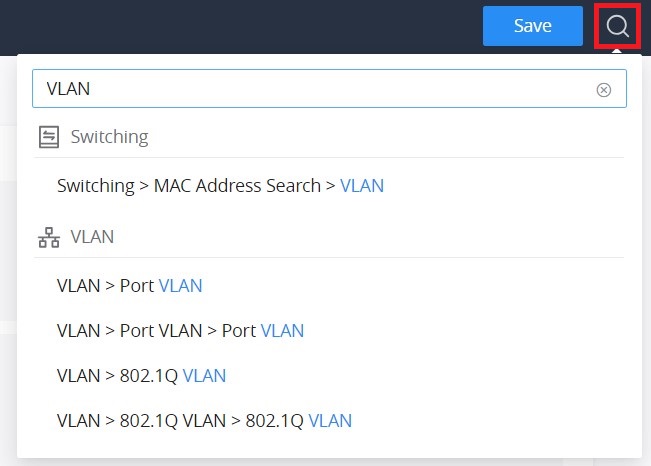
GWN772x Switches have search functionality to help the user find the right configuration, settings, parameters, etc.
On the top of the page, there is a search icon; the user can click on it and then enter the keyword relevant to their search, and then they will get all the possible locations of that keyword.
Language
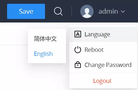
To change the language on the GWN772x switch interface:
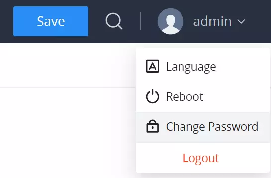
- Navigate to the top right corner of the interface where the username is displayed.
- Click on the drop-down menu next to the username.
- Select “Language” from the drop-down options.
- After selecting the language, the interface will switch to the chosen language.
Reboot
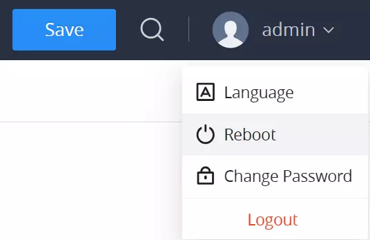
To reboot the GWN772x switch:
- Navigate to the top right corner of the interface where the username is displayed.
- Click on the drop-down menu next to the username.
- Select “Reboot” from the drop-down options.
- Confirm the action to reboot the device.
- The device will automatically restart after a brief delay.
Change Password
To change the password on your GWN772x switch:
- Navigate to the top right corner of the interface where the username is displayed.
- Click on the drop-down menu next to the username.
- Select “Change Password” from the drop-down options.
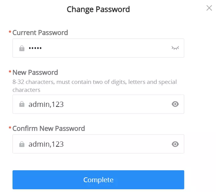
- A “Change Password” dialog box will appear.
- Enter the current password in the Current Password field.
- In the New Password field, input a new password that meets the criteria: it must contain 8-32 characters and include at least two of the following: digits, letters, and special characters (e.g.,
admin,123). - Enter the same password in the Confirm New Password field.
- Click “Complete” to apply the changes.
Logout
To log out of the GWN772x switch:
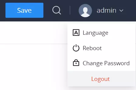
- Navigate to the top right corner of the interface where the username is displayed.
- Click on the drop-down menu next to the username.
- Select “Logout” to safely log out of the current session.
OVERVIEW
The overview is the first section that displays System information on the first page, “System Info”, and Port status on the second page, “Port Info”. This section provides the user with a general and global view of the GWN772x system and port status for easy monitoring.
System Info
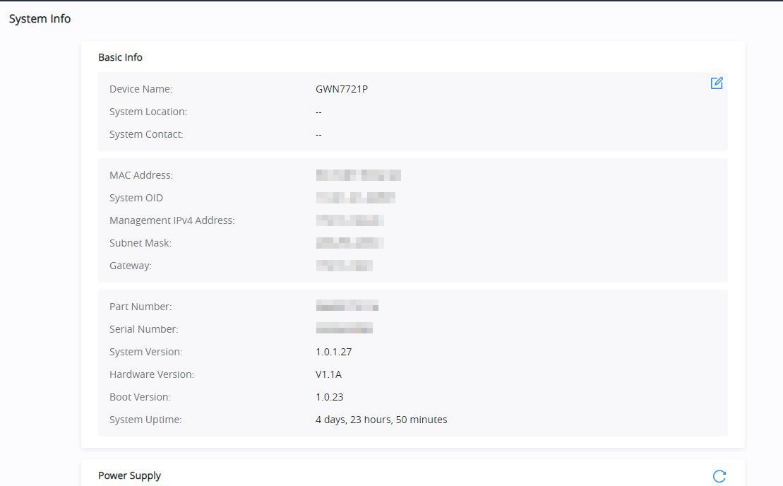
System Info is the first page after successfully logging into the GWN772x Web Interface. It provides an overall view of the GWN772x Switch information, like Device name, MAC Address, System Version, etc.
To name the device, please click on , then enter the desired name.
Port Info
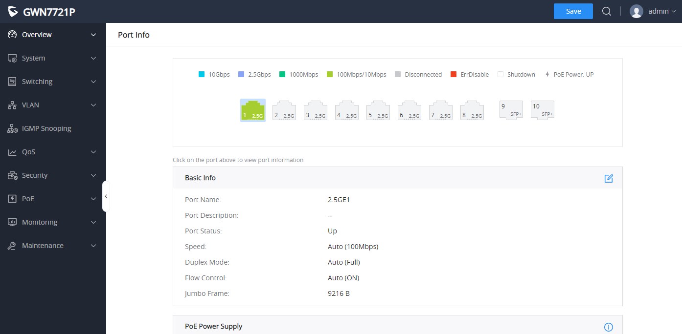
This page displays the status for each port on the GWN772x switches indicated by color code (green, red, grey, white, etc) and PoE symbol. Please refer to the figure below:
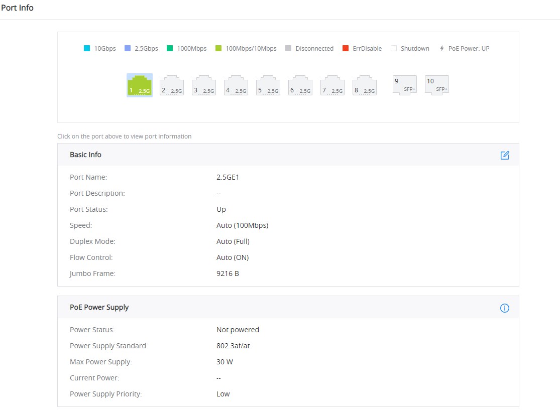
The following table explains the color code and the symbols used:
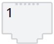 | Grey: Linkdown |
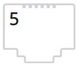 | White: shutdown |
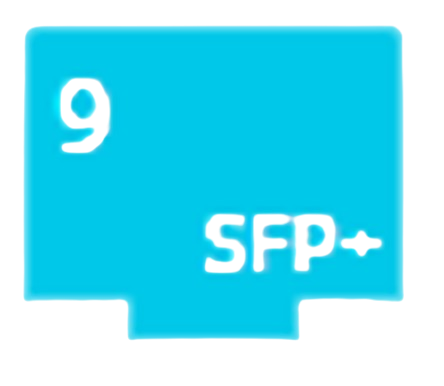 | Blue: 10 Gbps speed |
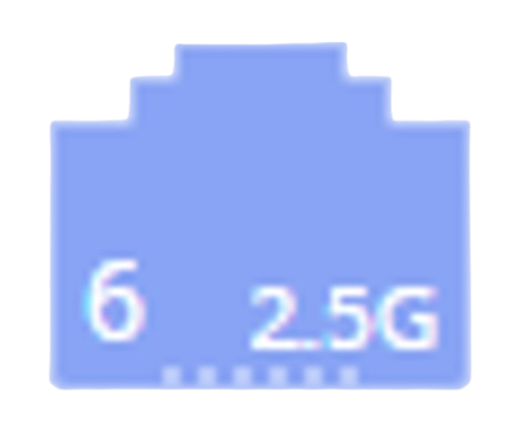 | Purple: 2.5 Gbps speed |
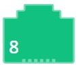 | Green: 1000 Mbps speed |
 | Light green: 100 Mbps/10 Mbps speed |
 | Red: ErrDisable |
 | Symbol: PoE Power is enabled. |
Ports Labels and Color Code
Note: A PoE symbol and color code combination is also possible. Ex:  in this case, the port is using 1000 Mbps speed and also using PoE at the same time.
There are 3 main sections for each port:
- Basic Info: displays info about the port name, speed, status, etc.
Note: Click on to modify the port settings like Description, Speed, Duplex Mode, and Flow Control, or to enable or disable the port.
- PoE Power Supply: displays PoE Current Power and priority, Status, etc.
Note: Click on to change PoE settings.
SYSTEM
IP Settings
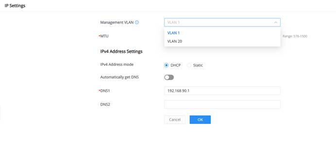
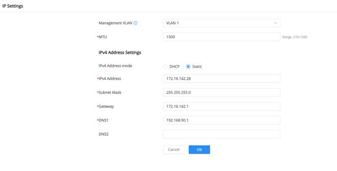
The IP Settings page controls the switch management interface. From this page, administrators can select the Management VLAN, obtain an address through DHCP or configure a Static IPv4 address, specify DNS servers, and set the Maximum Transmission Unit (MTU).
Management VLAN
The Management VLAN identifies the VLAN used to reach the switch’s management interface. Ensure the administrator’s device and the required switch ports can reach this VLAN before applying the change.
IPv4 Address Settings
Select DHCP to obtain the IPv4 address and DNS information automatically, or select Static to enter the IPv4 address, subnet mask, gateway, and DNS servers manually.
Maximum Transmission Unit (MTU)
The MTU specifies the maximum IP packet size, in bytes, used by the switch management interface. The supported range is 576–1500 bytes, and the default value is 1500 bytes. Use a smaller value only when required by the network path.
Field Name | Description |
Management VLAN | Selects the VLAN used to access the management interface. Only ports in this VLAN can access the web UI. Note: Management VLAN is only valid for 802.1Q VLAN, default VLAN1, that is, only ports under VLAN1 can access the Web page. |
MTU | Sets the Maximum Transmission Unit for the management interface. Range: 576 – 1500 (Default: 1500). |
IPv4 Address Mode | Choose between automatic (DHCP) or manual (Static) IP configuration. |
Automatically Get DNS | Enables automatic DNS retrieval from the DHCP server when set to DHCP mode. When disabled you can manually configure DNS1 and DNS2. |
DNS1 | Primary DNS server address. Note: This field is available in both DHCP and Static modes when the Automatically Get DNS option is disabled. |
DNS2 | Secondary DNS server address (optional). Note: This field is available in both DHCP and Static modes when the Automatically Get DNS option is disabled. |
IPv4 Address | Manually enter the desired static IP address for the switch. Note: This field is only available when Static mode is selected. |
Subnet Mask | Defines the subnet mask determining the network portion of the IP address. Note: This field is only available when Static mode is selected. |
Gateway | Defines the gateway used for external communications. Note: This field is only available when Static mode is selected. |
IP Settings
Management Platform
The Management Platform allows users to configure how the GWN772x switch connects to a management platform. The switch supports multiple management platforms, including GDMS Networking and GWN Manager. The management platform selection can either be automatic or manually specified by the user.
Steps to Configure the Management Platform
- Navigate to: System ➝ Management Platform.
- Enable DHCP Option 43: If needed, toggle on “Allow DHCP Option 43 to Override.”
- Select Connection Management Platform:
- Choose Auto for automatic platform selection.
- Select GDMS Networking or L2/L3 Manager, based on your setup.
- Specify Server Address and Port (if applicable):
- If a specific platform is selected (e.g., L3 Manager), input the server address and port number.
- Save your configuration.
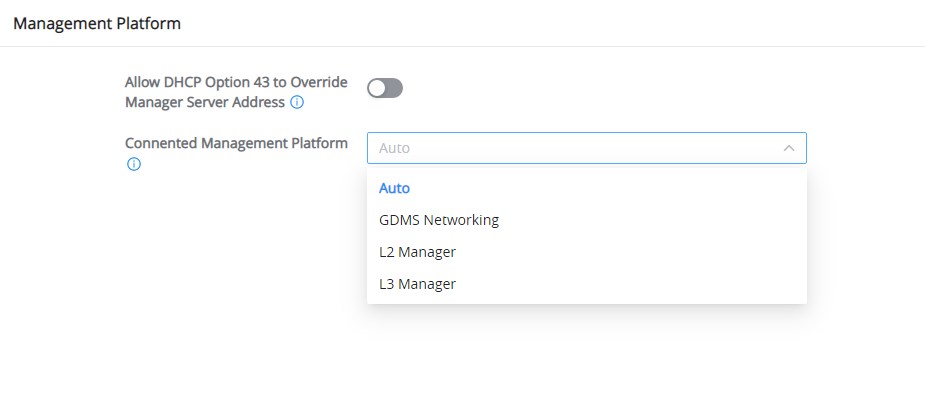
For more details, refer to this table:
Field | Description | Notes |
Allow DHCP Option 43 to Override | Enable or disable the DHCP Option 43 override. | If enabled, the server address assigned by DHCP Option 43 will be preferred. |
Connection Management Platform | Select the management platform type. Options include: Auto, GDMS Networking, L2 Manager, L3 Manager | Only one platform can be connected at a time, as well as discovered and taken over by one platform. By default, it is automatic, and the priority is to GDMS Networking. |
Server Address | Specify the server address of the selected management platform. | Only available when a manual platform (L3 Manager) is selected. Enter the IP address of the server. |
Server Port | Specify the server port of the selected management platform. | Only available when a manual platform (L3 Manager ) is selected. Enter the server port number (Range: 1-65535). |
Management platform
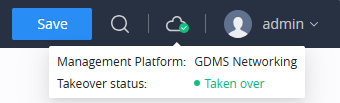
When the switch is successfully connected to a platform (either GDMS Networking or GWN Manager), a corresponding Cloud Icon with a green check mark will appear at the top of the Web UI. This icon signifies that the switch is now integrated with the management platform, and some configurations from the platform may now be applied to the switch, as shown below:
SWITCHING
The switching section covers Ports and LAG (Link Aggregation Group) configurations.
Port Settings
On this page, you can configure the basic parameters for GWN772x Switch ports, like disabling or enabling the port, adding a Description, specifying the speed, Duplex mode, and Flow Control.
To configure a port, please navigate to Switching → Port Settings.
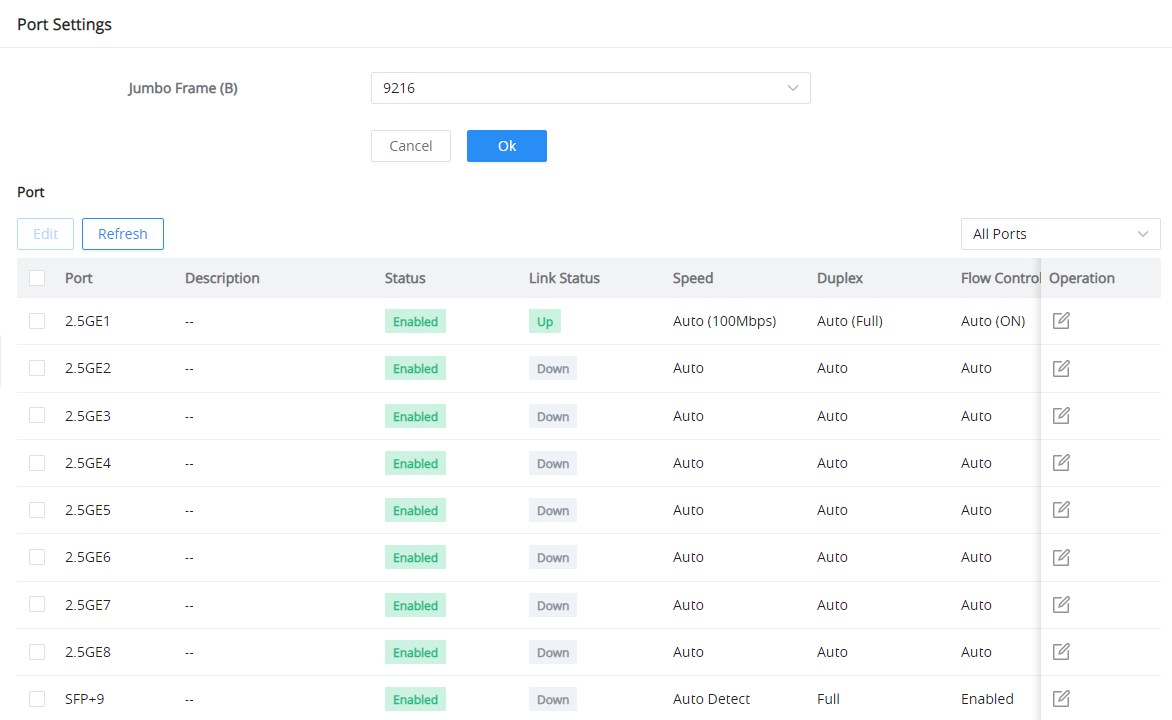
To configure a port, click on the “Edit” icon under the operation column.
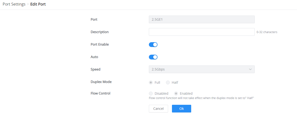
Port | The selected Port to be configured. |
Description | It is used to configure the information description of this interface , which can be a description of usage, etc., with a maximum of 32 characters, and the characters limited to input are numbers 0-9 , letters az / AZ and special characters. |
Port Enable | Set whether to enable the interface. it is enabled by default. |
Auto | toggle ON or OFF Auto Detect, if it’s ON the speed, Duplex Mode and Flow Control will be selected automatically, and if it’s OFF the user can select speed, Duplex Mode and Flow Control manually. |
Speed | Set the rate of the interface:
|
Duplex Mode | Set the duplex mode of the interface. The options are {full-duplex, half-duplex}. The default is Duplex.
|
Flow Control | Set the flow control on the interface, the options are {Disabled, Enabled}. The default is Enabled. After enabling it, if the local device is congested, it will send a message to the peer device to notify the peer device to temporarily stop sending packets, after receiving the message, the peer device will temporarily stop sending packets to the local and vice versa. Thus, the occurrence of packet loss is avoided. |
Port Settings – Edit port
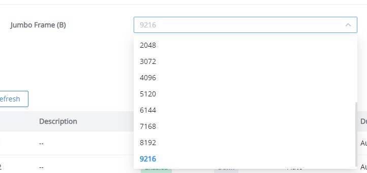
Jumbo Frame
The maximum Transmission Payload or MTU is typically 1500 bytes. In case the user requires even a bigger MTU length for a specific scenario, there is an option on the GWN772x Switch to enable Jumbo Frame; the maximum Ethernet frame size ranges from 1518 to 9216 bytes. The default value is 9216 bytes.
LAG
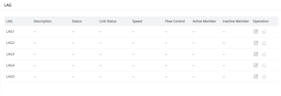
LAG means Link Aggregation Group, which groups some physical ports to make a single high-bandwidth data path. Thus, it can implement traffic load sharing among the member ports in a group to enhance the connection reliability.
To configure LAG, please navigate to Switching → LAG.
GWN772x switches support up to 5 link aggregation groups, as shown in the figure below:
To edit/configure a LAG, click on the “Edit” icon under the operation column.
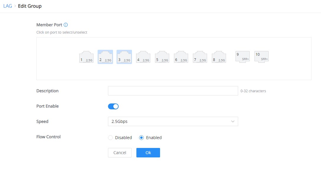
Member Port | Click on ports to be part of this LAG group. |
Description | It is used to configure the information description for this LAG , which can be a description of usage, etc., with a maximum of 32 characters, and the characters limited to input are numbers 0-9 , letters az / AZ and special characters. |
Port Enable | Set whether to enable the interface. it is enabled by default. |
Speed | Set the rate of the interface, the options are {10Mbps, 100Mbps, 1000Mbps, 2.5Gbps} for ethernet ports and {1000Mbps, 2.5Gbps, and 10Gbps} for SFP+ ports. The default is 2.5Gbps for Ethernet ports, and 10Gbps for SFP+ ports. |
Flow Control | Set the flow control on the interface, the options are { Disabled, Enabled}. The default is Enabled. After enabling it, if the local device is congested, it will send a message to the peer device to notify the peer device to temporarily stop sending packets, after receiving the message, the peer device will temporarily stop sending packets to the local and vice versa. Thus, the occurrence of packet loss is avoided. |
Edit LAG
MAC Address Search
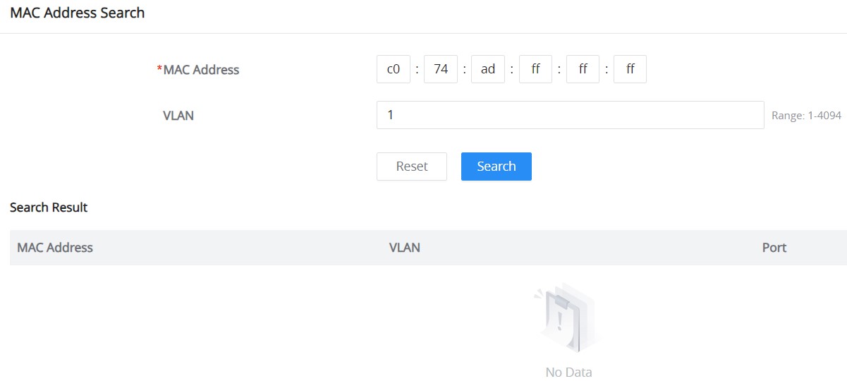
The MAC address table records the correspondence between the MAC addresses of other devices learned by the switch and the interfaces, as well as information such as the VLANs to which the interfaces belong. When forwarding a packet, the device queries the MAC address table according to the destination MAC address of the packet. If the MAC address table contains an entry corresponding to the destination MAC address of the packet, it directly forwards the packet through the outbound interface in the entry. If the MAC address table does not contain an entry corresponding to the destination MAC address of the packet, the device will use broadcast mode to forward the packet on all interfaces in the VLAN to which it belongs, except the receiving interface.
On this page, the user can search using the MAC address and the VLAN. If the device’s MAC address is found, it will be displayed on the Search Result section.
Spanning Tree
The Spanning Tree Protocol (STP) prevents network loops by creating a loop-free topology in Ethernet networks. It allows redundant paths without causing broadcast storms or multiple frame copies.
Global Settings – Spanning Tree
The Global Settings tab in the Spanning Tree section lets administrators configure general Spanning Tree settings and view real-time status.
To access Spanning Tree Global Settings:
- Navigate to Switching → Spanning Tree → Global Settings.
- Enable Spanning Tree by toggling the switch to ON.
- Configure the following fields:
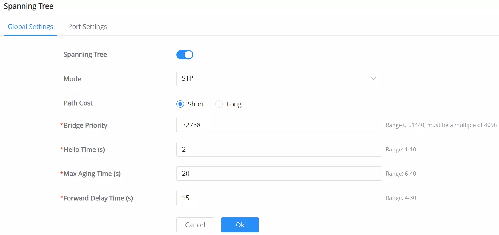
Field Name | Description | Range |
Mode | Choose between STP (Spanning Tree Protocol) and RSTP (Rapid Spanning Tree Protocol). Note: RSTP is faster in convergence and more efficient in modern networks. | – |
Path Cost | Select either Short or Long path cost calculation. Note: Short uses the IEEE 802.1D standard while Long supports larger path costs for higher-speed links. | – |
Bridge Priority | The lower the value the higher the chance of this switch becoming the root bridge. Note: Adjust this based on network topology. | Range 0-61440, must be a multiple of 4096 |
Hello Time (s) | Defines the time interval between BPDU transmissions by the root bridge. | 1 – 10 seconds |
Max Aging Time (s) | Sets how long the switch will keep BPDU information before discarding it. | 6 – 40 seconds |
Forward Delay Time (s) | Determines how long a port spends in Listening and Learning states before transitioning to Forwarding. | 4 – 30 seconds |
Spanning Tree – Global Settings
This section displays the current status of the spanning tree topology. You can refresh the information by clicking the Refresh icon.
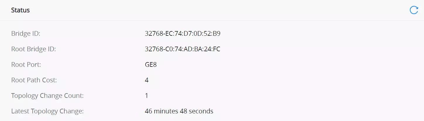
Field Name | Description |
Bridge ID | The unique identifier for the current bridge (switch). |
Root Bridge ID | The identifier for the root bridge in the spanning tree topology. |
Root Port | The port used to reach the root bridge. |
Root Path Cost | The cost of the path to the root bridge from this switch. |
Topology Change Count | The number of times the network topology has changed. |
Latest Topology Change | The time since the last topology change. |
Spanning Tree – Real-Time Status Information
Port Settings – Spanning Tree
The Port Settings tab allows configuration of Spanning Tree on a per-port basis, enabling administrators to control port behavior, priority, path cost, and monitor port status.
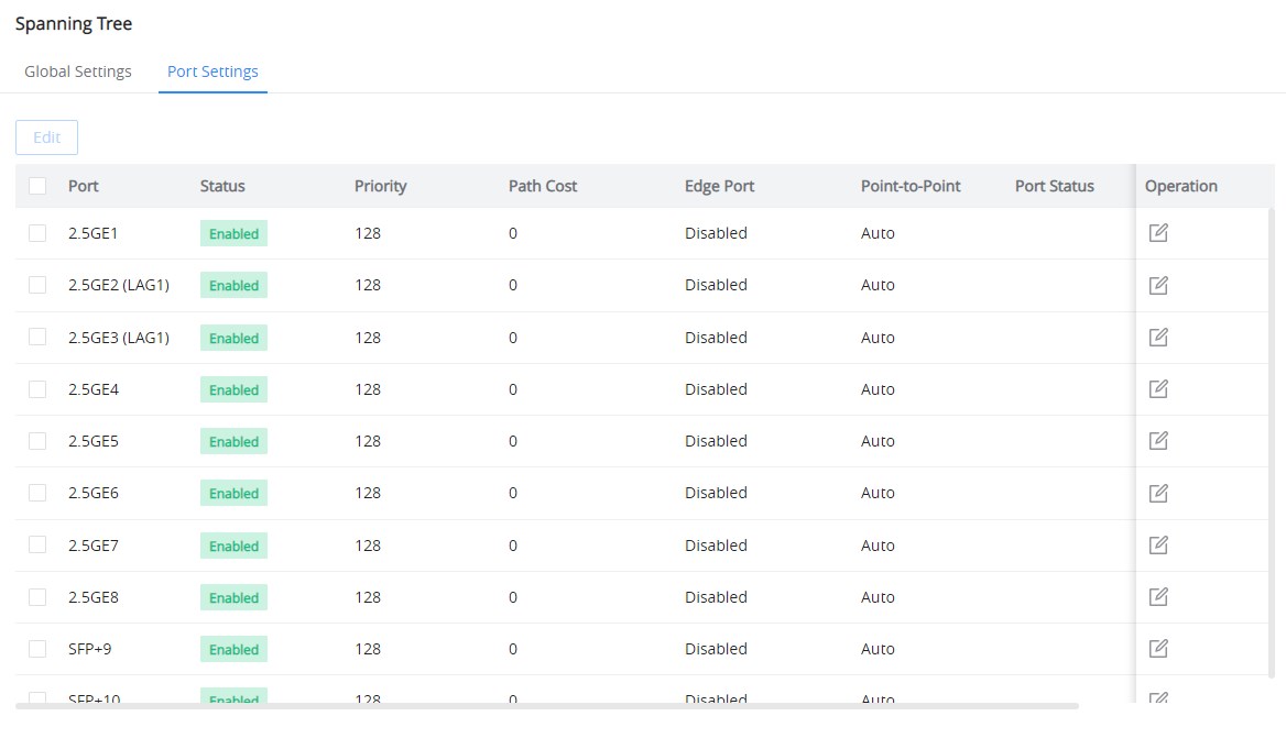
To configure Spanning Tree on specific ports:
- Navigate to Switching → Spanning Tree → Port Settings.
- Select the port you wish to configure and click Edit.
- Configure the following fields:
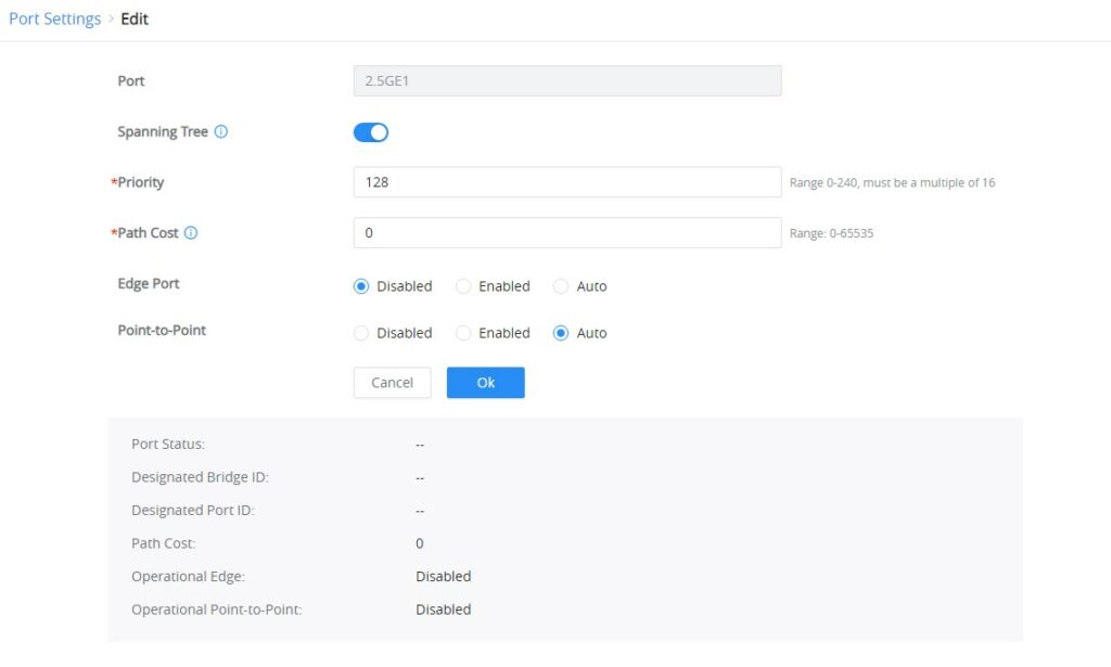
Field Name | Description | Range |
Port | The specific port being configured for Spanning Tree Protocol. | – |
Spanning Tree | Enables or disables Spanning Tree for the selected port. Note: If the port is self-looping, the port will be automatically shut down, and the port needs to be manually enabled again. | – |
Priority | Assigns priority to the port. Lower values make this port more likely to become the root port in case of a tie. | 0 – 240 (multiples of 16) |
Path Cost | Defines the cost of using this port to reach the root bridge. Lower costs indicate more desirable paths. The default value is 0 meaning the switch automatically calculates based on link speed. | Range: 0-65535 |
Edge Port | Enable if the port is connected to an end device and is not expected to receive BPDUs. Auto will detect if the port should behave as an edge port. | – |
Point-to-Point | Specifies whether the port operates as a point-to-point link. Auto allows detection of the link type. | – |
Spanning Tree – Port Settings
Port Status
This section provides real-time information about the selected port’s spanning tree status.
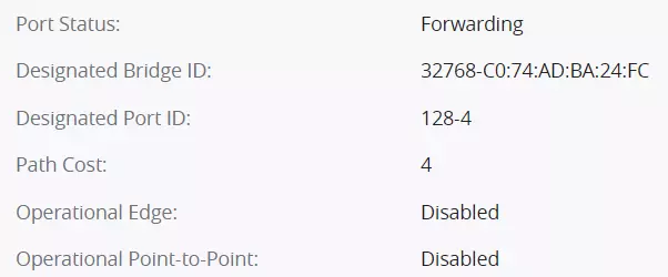
Field Name | Description |
Port Status | Indicates whether the port is currently active |
Designated Bridge ID | The bridge ID of the designated bridge for the port. |
Designated Port ID | The ID of the port designated for this spanning tree configuration. |
Path Cost (Status) | Displays the actual path cost currently being used by the port. |
Operational Edge | Shows whether the port is operating as an edge port. |
Operational Point-to-Point | Displays whether the port is operating as a point-to-point link. |
Spanning Tree – Port Status
VLAN
A virtual local area network, virtual LAN or VLAN, is a group of hosts with a common set of requirements that communicate as if they were attached to the same broadcast domain, regardless of their physical location. A VLAN has the same attributes as a physical local area network (LAN), but it allows for end stations to be grouped even if they are not located on the same network switch. VLAN membership can be configured through software instead of physically relocating devices or connections.
Port VLAN
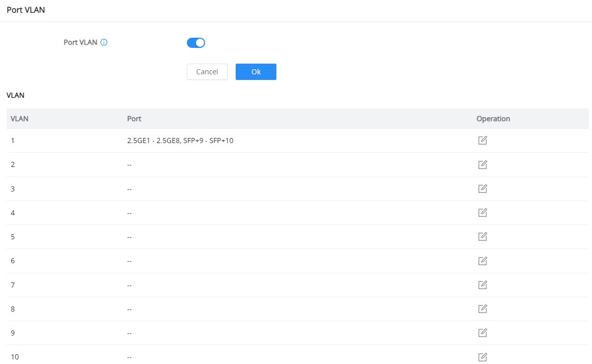
On this page, the user can select which VLANs (a preset from 1 to 8) can be allowed on GWN772x ports. This is a simplified way to manage VLANs from 1 to 8. To have more flexibility and control, please enable 802.1Q VLAN, and the Port VLAN will be disabled automatically.
First, enable Port VLAN as shown below:
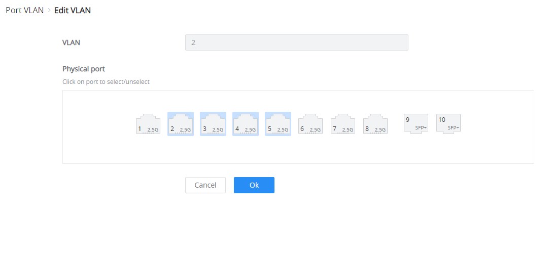
Click the “Edit” icon under the Operation column to edit a VLAN, then select which ports this VLAN will be allowed on.
802.1Q VLAN
For more flexibility and control over VLAN configuration, the user can enable 802.1Q VLAN, and in this case, the user is not only restricted to VLANs from 1 to 8.
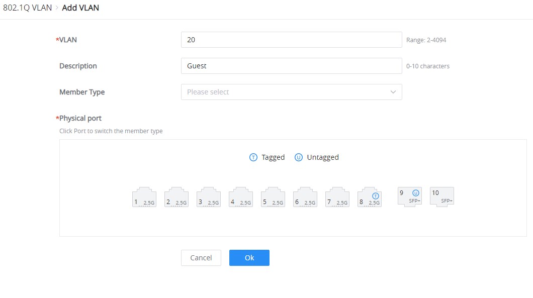
Click on the “Add” button to add a VLAN, as shown below:
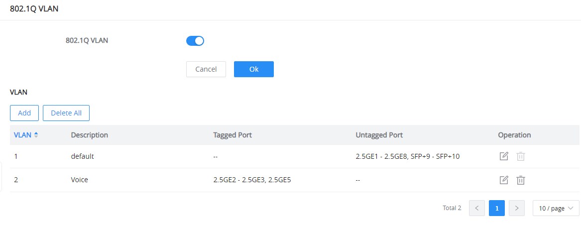
On this screen, the user can configure the VLAN:
- VLAN: specify the VLAN ID (Range 2-4094).
- Description: Enter a description for the VLAN.
- Member Type: a shortcut to untag/tag or remove all members.
- Physical port: select the tagged/untagged ports accordingly.
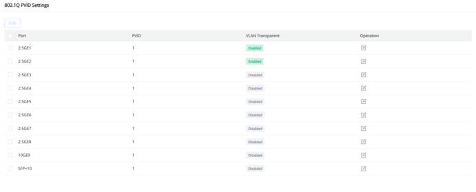
802.1Q PVID Settings
If the 802.1Q VLAN is enabled, the user can select the PVID (Port VLAN ID) or native VLAN when there is more than one VLAN on a port. Click on the “Edit” icon under operation to modify the PVID on a specific port.
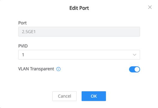
When editing a port, the following options are available:
- PVID (Port VLAN ID): Assigns the default VLAN ID for untagged traffic entering the port. All untagged packets received on this port will be associated with the configured PVID.
- VLAN Transparent: When enabled, the port bypasses the local 802.1Q VLAN table and directly forwards all VLAN-tagged packets without modification. This allows the port to act as a VLAN-agnostic pass-through, useful when the switch should not enforce VLAN isolation (e.g., when passing VLANs between two VLAN-aware devices).
IGMP SNOOPING
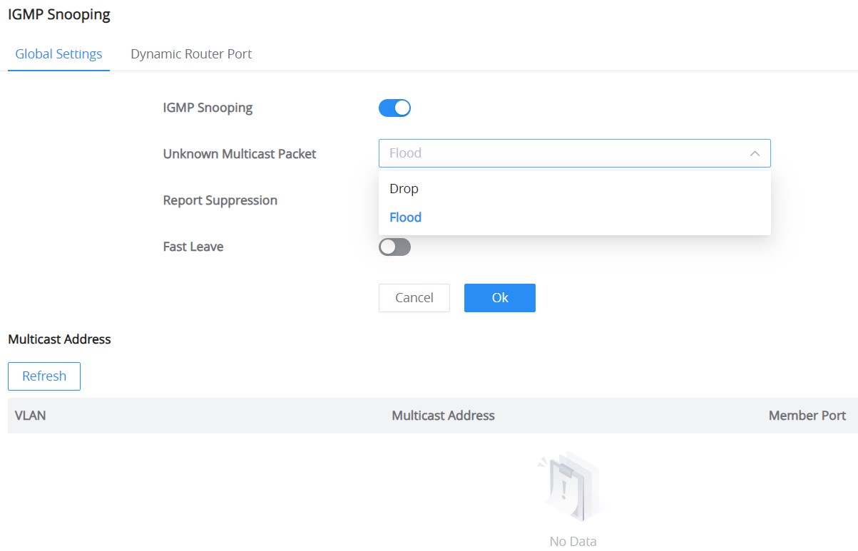
The GWN772x switches support IGMP snooping, which is an IPv4 Layer 2 multicast protocol that optimizes the handling of multicast traffic in a network by intelligently forwarding traffic only to the ports where interested hosts are located, based on the monitoring of IGMP messages.
On the Global Settings tab, the users can enable the IGMP Snooping feature by toggling ON the feature, and for an Unknown Multicast Packet will be either dropped or flooded as shown below:
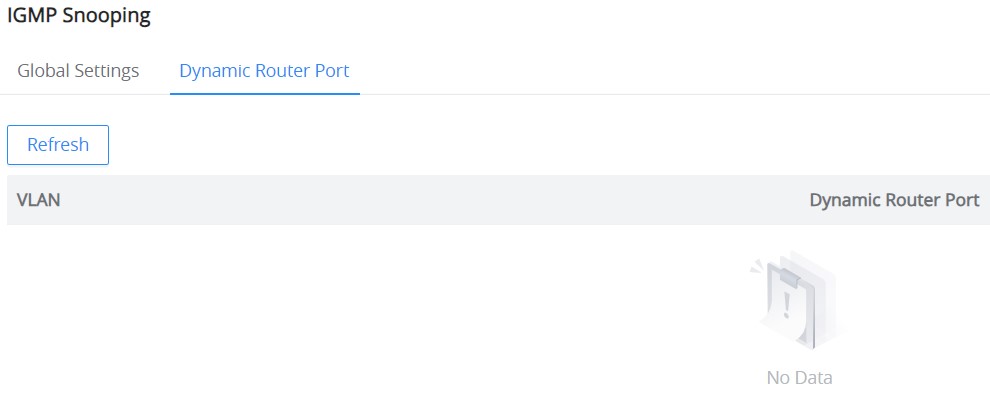
IGMP snooping dynamically identifies router ports by monitoring IGMP General Query messages and optimizes the forwarding of multicast traffic to those ports for efficient use of network bandwidth.
The Dynamic Router Port tab displays all the discovered dynamic router ports. The users can click on the “Refresh” button to refresh the list.
QOS
The popularity of the network and the diversification of services have led to a surge in Internet traffic, resulting in network congestion, increased forwarding delay, and even packet loss in severe cases, resulting in reduced service quality or even unavailability. Therefore, to carry out these real-time services on the network, it is necessary to solve the problem of network congestion. The best way is to increase the bandwidth of the network, but considering the cost of operation and maintenance, this is not realistic. The most effective solution is to apply” Guaranteed ” policies to govern network traffic. QoS technology is developed under this background. QoS is quality of service, and its purpose is to provide end-to-end service quality assurance for various business needs. QoS is a tool for effectively utilizing network resources. It allows different traffic flows to compete for network resources unequally. Voice, video, and important data applications can be prioritized in network equipment.
QoS Basic Settings
On this page, the user can edit the port priority for each port. The supported modes are:
- Port-Based
- 802.1P-Based
- DSCP-Based
Please navigate to QoS → QoS Basic Settings page:
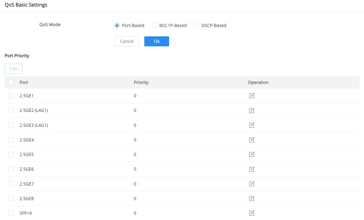
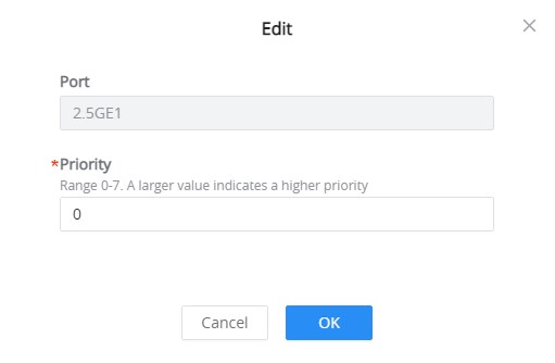
Select one or multiple ports, then click on the “Edit” button to modify the ports’ priority. The priority range is from 0 to 7; a larger value indicates a higher priority, and value 0 is the default value.
Priority Mapping
Priority mapping is used to realize the conversion between the QoS priority carried in the packet and the internal priority of the device ( also known as the local priority, which is the priority used by the device to differentiate the service level of the packet ) so that the device provides the Differentiated QoS service quality. Users can use different QoS priority fields in different networks according to network planning.
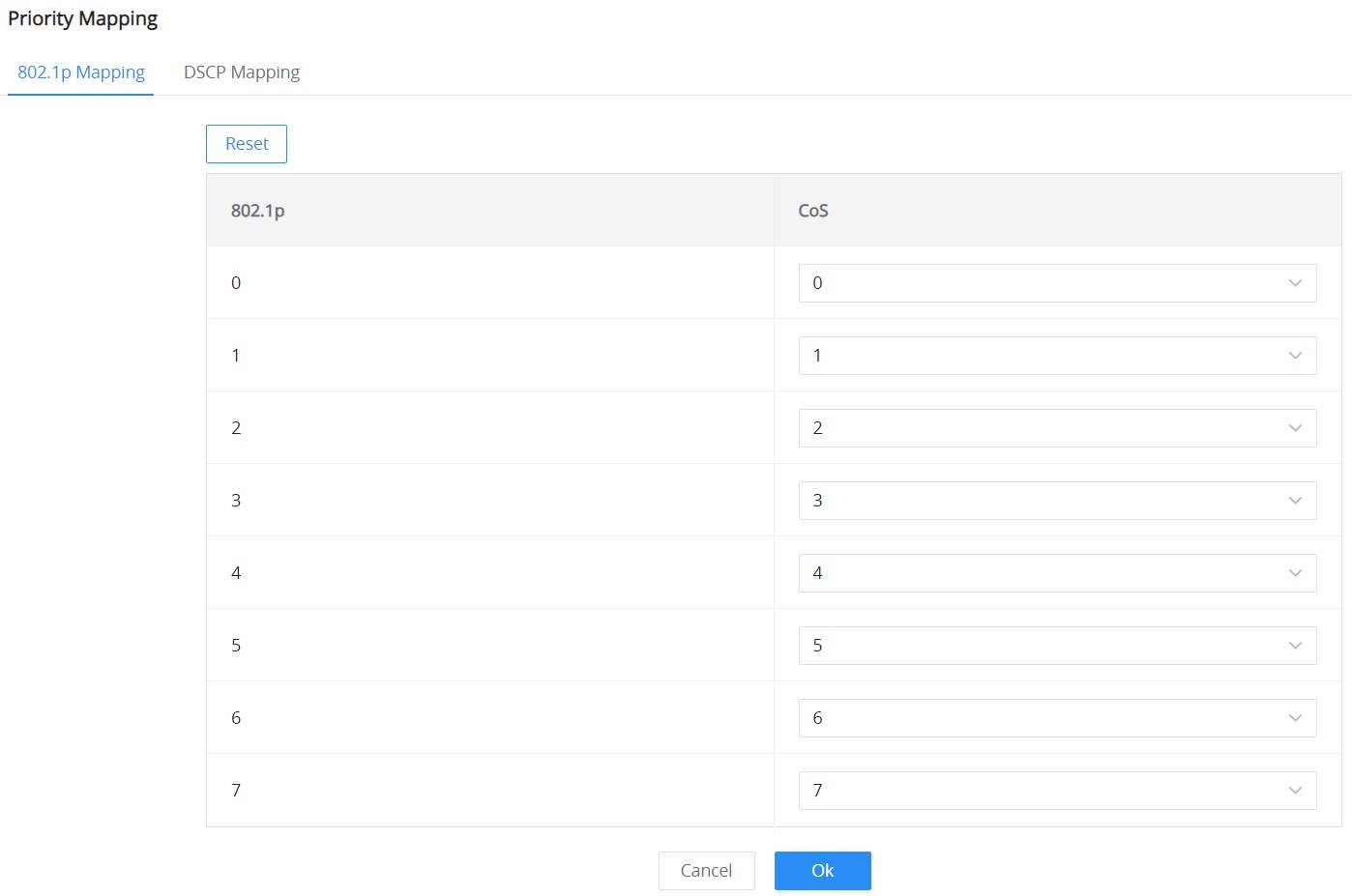
- 802.1p Mapping
On this tab, the user can map between 802.1p and CoS (Class of Service) where 0 is the lowest priority and 7 is the highest priority for 802.1p, and by default, CoS is set to be the same (it’s recommended to keep it by default only if necessary or a specific network requires it).
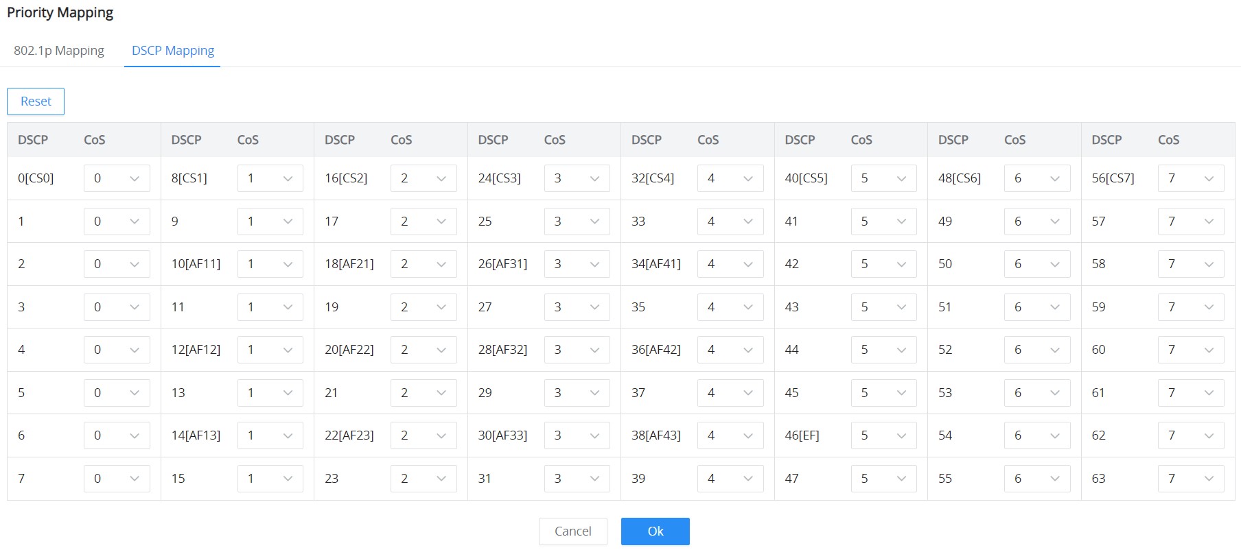
- DSCP Mapping
On this tab, the user can map between CoS and DSCP (Differentiated Services Code Point); in this case, 802.1p and CoS mapping must be configured first. (It’s recommended to keep the default settings to keep the consistency between all switches, only if it’s necessary or the network requires it.)
Queue Scheduling
When congestion occurs in the network, the device will determine the processing order of forwarding packets according to the specified scheduling policy, so that high-priority packets are preferentially scheduled.
Queue scheduling algorithm: queue scheduling according to the switch interface.
- Strict priority (SP) scheduling: The flow with the highest priority is served first, and the flow with the second highest priority is served until there is no flow at that priority. Each interface of the switch supports 8 queues ( queues 0-7 ), queue 7 is the highest priority queue, and queue 0 is the lowest priority queue. Disadvantage: When congestion occurs, if there are packets in the high-priority queue for a long time, the packets in the low-priority queue cannot be scheduled, and data cannot be transmitted.
- Weighted Fair Queuing (WFQ) scheduling: Based on ensuring fairness (bandwidth, delay) as much as possible, priority considerations are added, so that high-priority packets have more opportunities for priority scheduling than low-priority packets. WFQ can automatically classify flows by their “session” information (protocol type, source and destination IP addresses, source and destination TCP or UDP ports, priority bits in the ToS field, etc.) Place each flow evenly into different queues, thus balancing the latency of the individual flows as a whole. When dequeuing, WFQ allocates the bandwidth that each flow should occupy at the egress according to the flow priority (Precedence). The smaller the priority value is, the less bandwidth is obtained; otherwise, the more bandwidth is obtained.
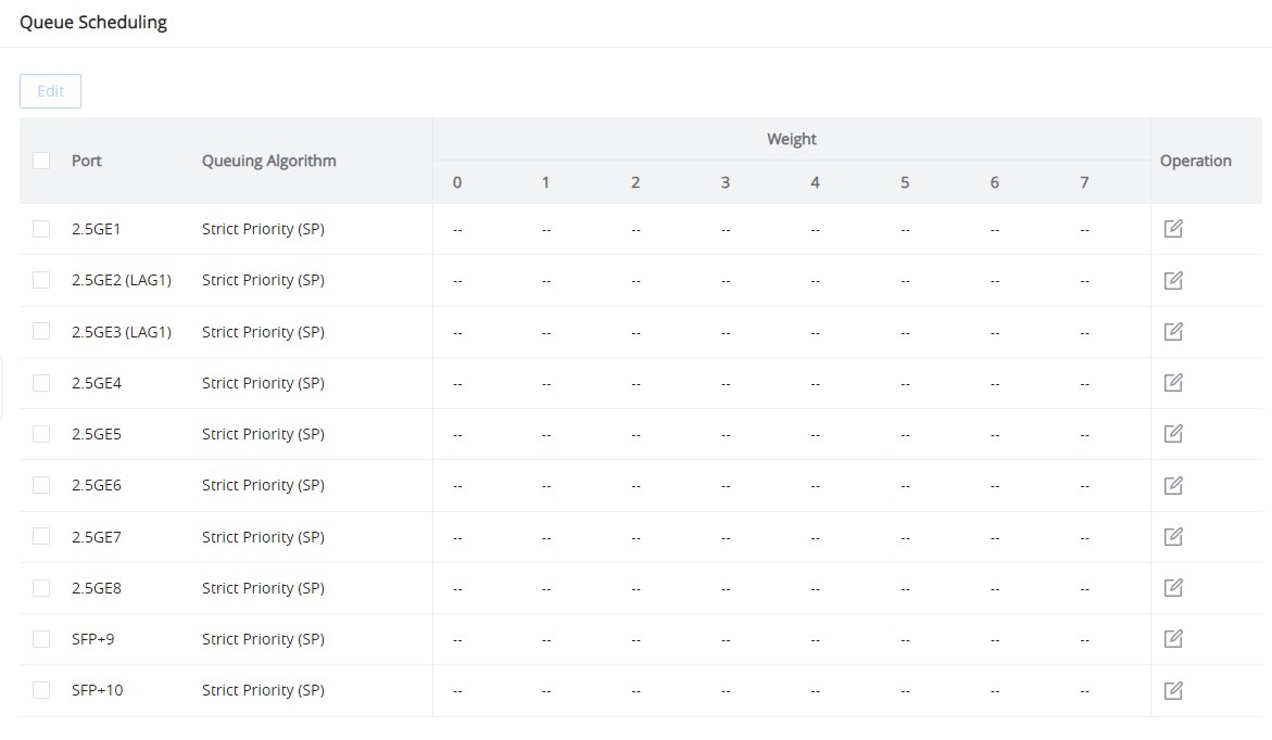
Select one or multiple ports, then click on the “Edit” button to modify the ports’ Queuing Algorithm. The default algorithm is set to Strict Priority (SP).
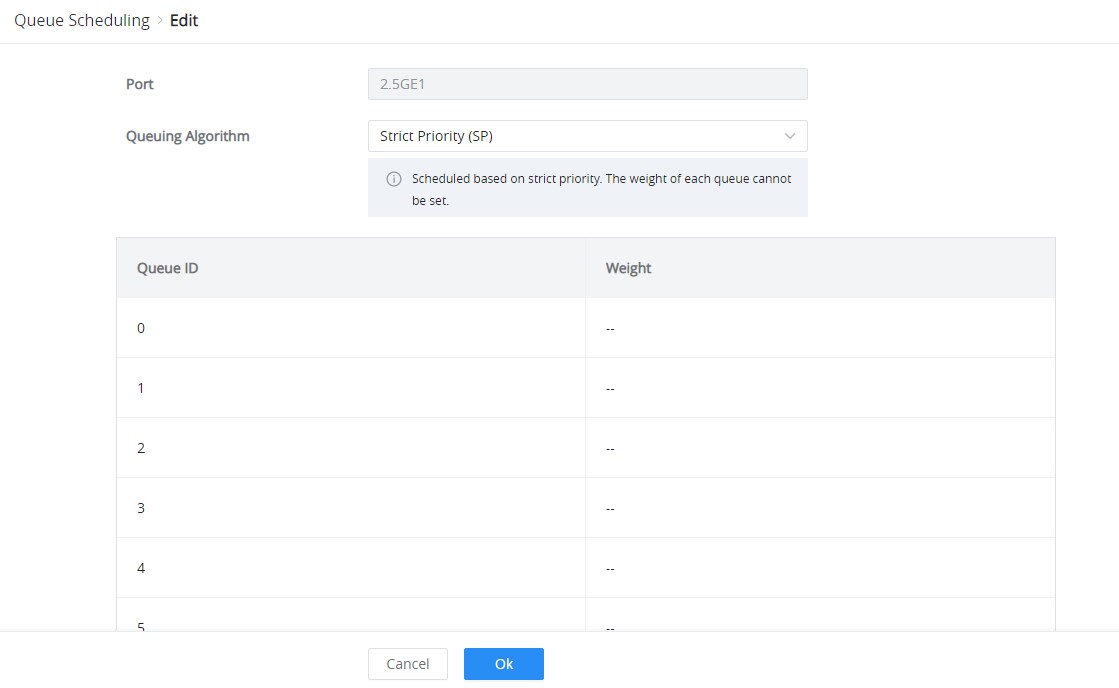
If Weighted Fair Queuing (WFQ) is selected, the Weight option can be configured accordingly; the higher the Weight, the higher the traffic priority.
Rate Limit
The interface rate limit can limit the total rate of all packets sent or received on an interface. The interface rate limit also uses the token bucket to control the flow. If an interface rate limit is configured on an interface of the device, all packets sent through this interface must first be processed through the token bucket of the interface rate limiter. If there are enough tokens in the token bucket, the packet can be sent; otherwise, the packet will be discarded or cached.
To configure Rate Limit, please navigate to QoS → Rate Limit, then select one or multiple ports, click on the “Edit” button to edit the port(s).
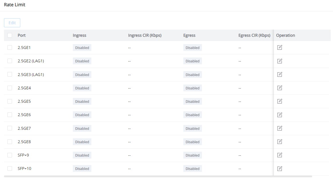
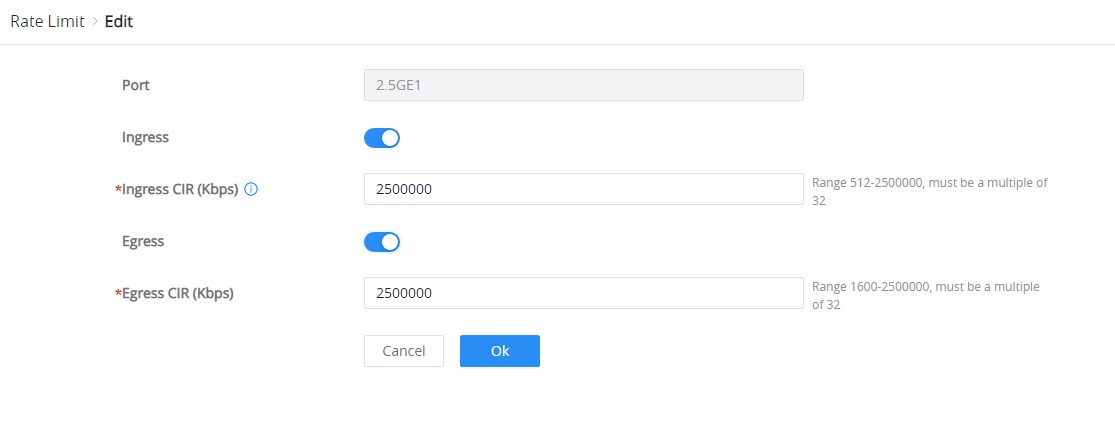
Enable the Ingress (incoming traffic to the switch) and then set the rate limit (in Kbps), and then enable Egress (outgoing traffic) and set the rate limit (in Kbps).
Security
DHCP Snooping
DHCP Snooping is a security feature that protects against rogue DHCP servers. It allows network administrators to specify trusted and untrusted ports, ensuring that only legitimate DHCP servers can provide IP addresses. Untrusted ports will drop DHCP server responses from unauthorized servers, while trusted ports will allow traffic from legitimate DHCP servers.
To enable DHCP Snooping:
- Log in to the Web UI of your GWN772x switch.
- Navigate to:
- Security → DHCP Snooping
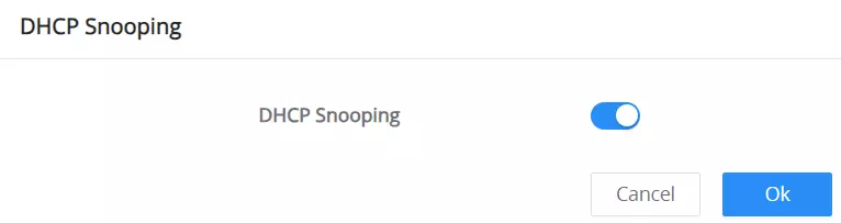
- Enable DHCP Snooping globally by toggling the switch at the top of the page.
Once enabled, DHCP Snooping will monitor and filter DHCP traffic on all interfaces.
DHCP Snooping Port Settings
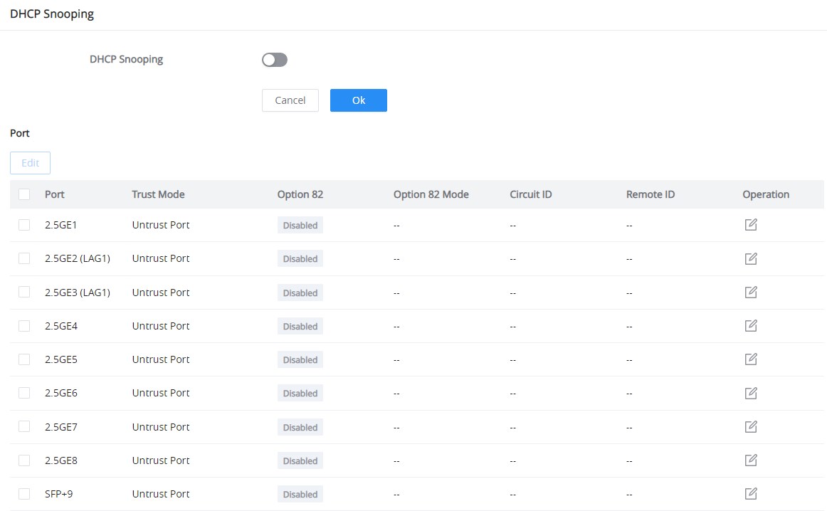
Configure the trusted/untrusted status of each port and whether DHCP Option 82 is enabled, to help with tracking and security.
Port-Specific Settings: You can configure DHCP Snooping on individual ports.
- Click Edit next to the port you want to configure.
- The following fields can be adjusted:
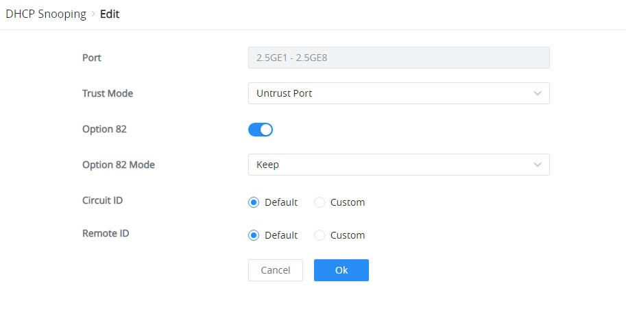
Field | Description | Note |
Port | The interface where DHCP Snooping is configured. | Available for all ports. |
Trust Mode | Specifies whether the port is trusted or untrusted. | Note: Trusted ports accept DHCP packets from legitimate DHCP servers and untrusted ports drop DHCP server packets. |
Option 82 | Enables DHCP Option 82 | which is used to add additional information (Relay Agent Information) in DHCP requests. |
Option 82 Mode | Determines how the relay information should be handled. | Options are: Keep, Drop and Replace. |
Circuit ID | The circuit ID that identifies the connection. Can be set to ‘Default’ or ‘Custom’. | Only available when ‘Option 82’ is enabled. |
Remote ID | The remote ID that provides information about the remote connection. Can be set to ‘Default’ or ‘Custom’. | Only available when ‘Option 82’ is enabled. |
DHCP Snooping Edit port
POE
Power Over Ethernet (PoE) refers to supplying power over an Ethernet network, also known as a local area network-based power supply system, PoL, or Active Ethernet.
Usually, the terminal devices of the access point need to use a DC power supply, but due to insufficient wiring, these devices need unified power management. At this time, the switch interface provides the power supply function, which can solve the above problems and realize the precise control of the port PoE power supply.
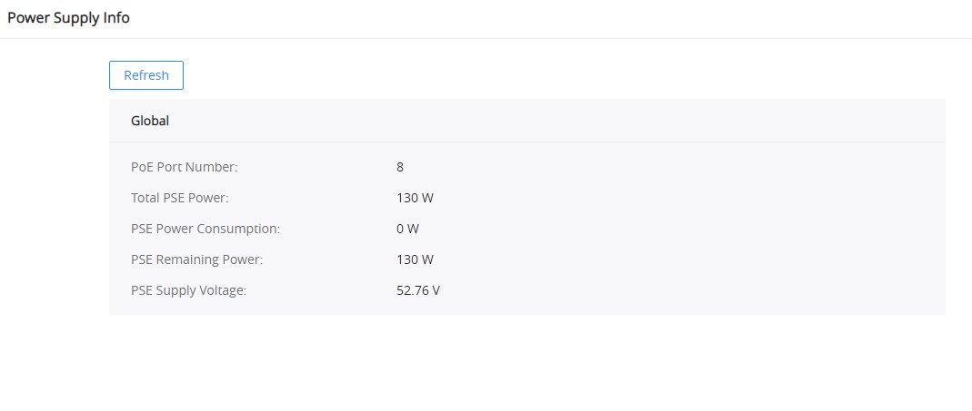
Power Supply Info
This page displays the Power Supply Info like the number of PoE, Total, Remaining PoE Power, etc, and even the Supply Voltage.
Power Supply Setting
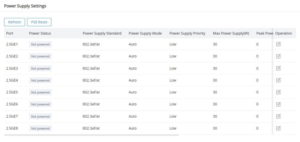
On this page, the user can configure on each port that supports PoE: The max power supply, the power supply priority, and the power supply mode. For example, GWN7721P ports 1–8 support PoE/PoE+. On the GWN7721PE, ports 1–8 support PoE/PoE+, while port 9 additionally supports PoE++ with up to 90 W output.
To reset the PSE, click on the “PSE Reset” button as shown below:
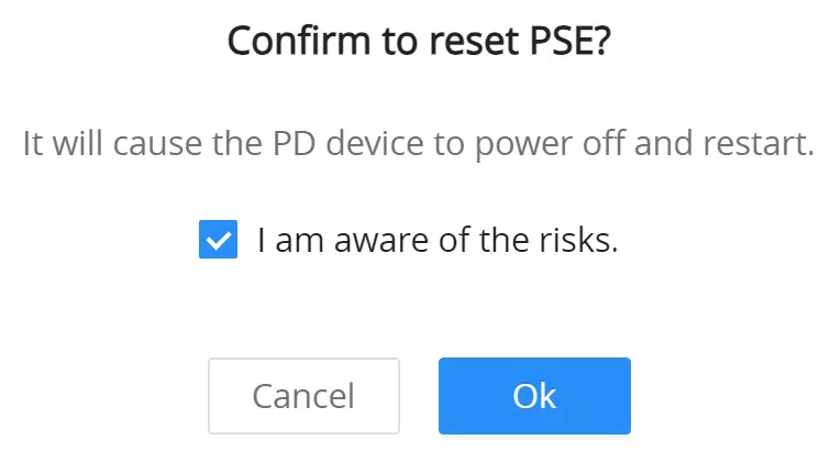
When resetting the Power Sourcing Equipment (PSE) on the GWN7721P or GWN7721PE switch, a confirmation dialog appears, warning that this action will power off and restart all connected Powered Devices (PDs). The user must acknowledge the risk by selecting the checkbox and clicking “Ok” to proceed.
To edit the PoE parameters on the supported port, click on the “Edit icon” under the operation column, then select from the drop-down lists the power supply standard, power supply mode, and power supply priority.
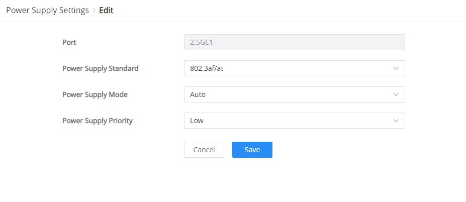
When multiple Powered Devices (PDs) are connected and the PoE power budget is limited, the GWN772X prioritizes power supply based on the power-on time of the connected devices.
If multiple ports have the same configured PoE priority, the device that was powered on earlier will have higher priority to retain power.
Example: If two PDs are connected to Port 3 and Port 7 with equal priority settings, and the available PoE budget becomes insufficient to power both, the device that was connected or powered on first will continue receiving power, while the latter one may be disconnected.
PoE Watchdog
The PoE Watchdog feature is designed to monitor the connectivity of Powered Devices (PD) on PoE-enabled ports. The switch periodically sends packets to a configured IP address to check the PD’s availability. If the PD does not respond, the switch will disable and re-enable the PoE on that port, effectively rebooting the device. This feature is useful for ensuring the continuous operation of critical devices like IP cameras, access points, or VoIP phones.
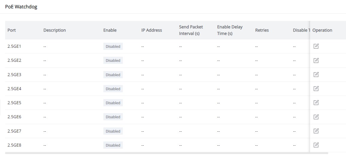
Steps to Configure PoE Watchdog
- Navigate to PoE → PoE Watchdog from the web interface.
- Click on the edit icon next to the port you want to configure.
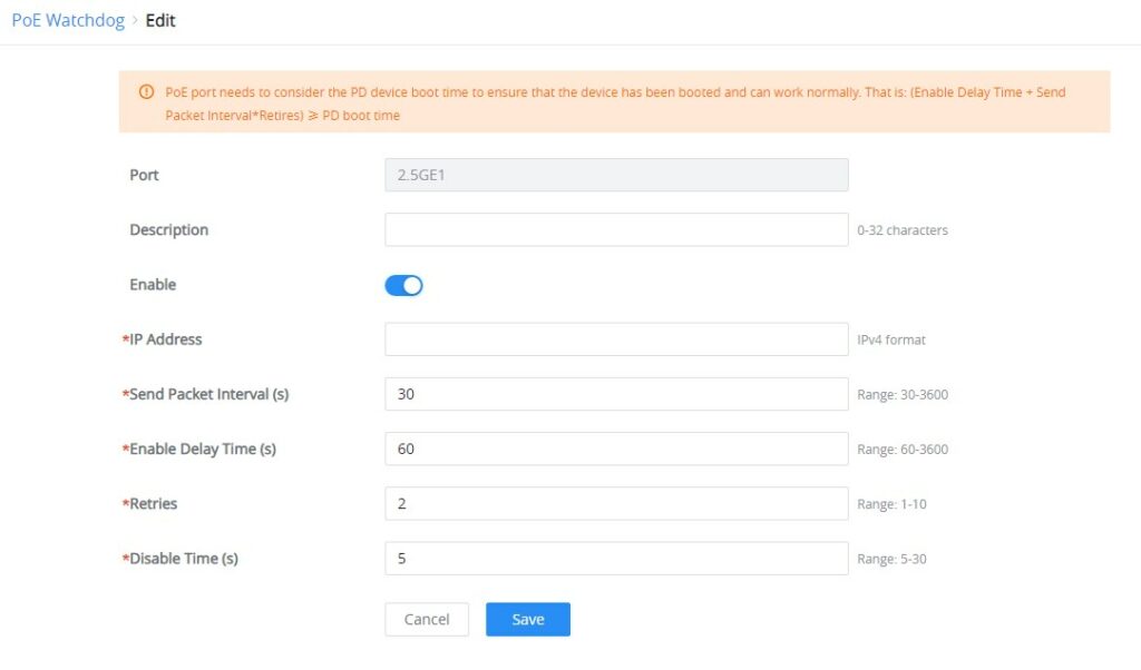
- In the edit page, configure the following fields:
- Port: Select the port to monitor.
- Description: (Optional) Describe the port.
- Enable: Toggle to enable or disable PoE Watchdog for this port.
- IP Address: Enter the IP address of the device to ping.
- Send Packet Interval (s): Set the interval between ping packets.
- Enable Delay Time (s): Set the delay time before enabling the PoE watchdog.
- Retries: Configure the number of ping retries before considering the device unreachable.
- Disable Time (s): Set the time to disable PoE before re-enabling it.
MONITORING
Port Statistics
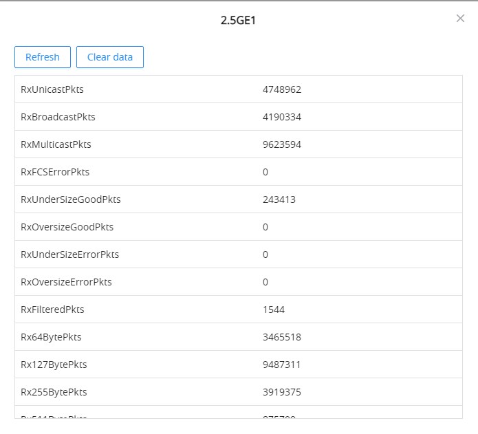
For monitoring or even sometimes troubleshooting, the Flow Statistics displays in real time the flow of data with different units like Octets, Packets, Transmission Rate, and OutErrPackets.
To refresh the statistics, click on the “Refresh” button, and to clear all the statistics, click on the “Clear All” button.
To clear the data for a specific port, click on the “clear icon” under the operation column.
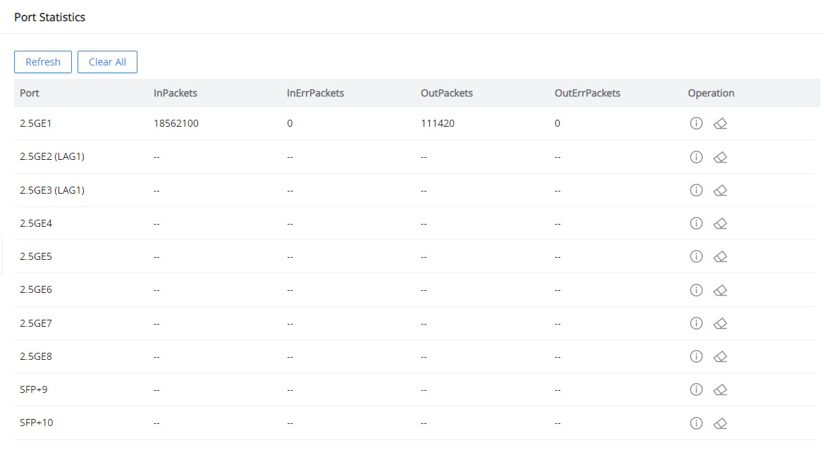
For more details, click on the “Exclamation mark icon” under the operation column next to each port.
Port Mirror
Mirroring refers to copying the packets from the specified source to the destination port. The specified source is called the mirroring source, the destination port is called the observing port, and the copied packet is called the mirroring packet.
Mirroring can make a copy of the original packet without affecting the normal processing of the original packet by the device, and send it to the monitoring device through the observation port to determine whether the service running on the network is normal.
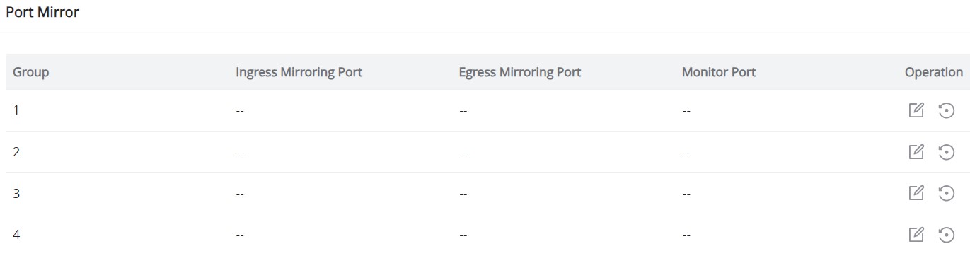
GWN772x switch supports up to 4 groups. To configure/edit a group, click on the “Edit icon” under the operation column.
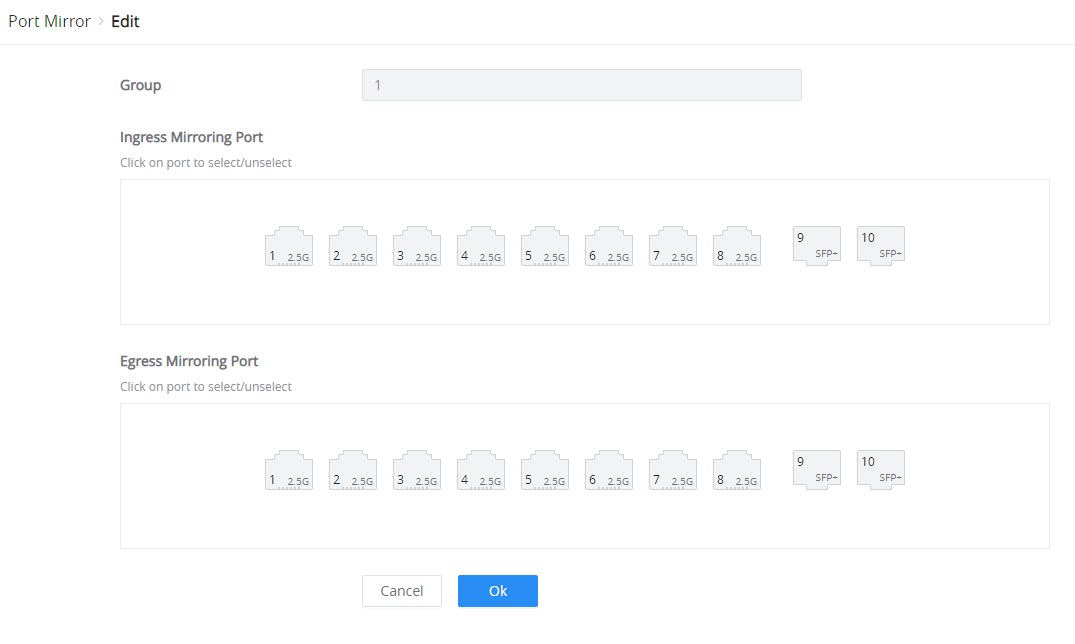
To start mirroring a port, first, select the Ingress (incoming traffic to the switch) Mirroring port, then select the Egress (outgoing traffic) Mirroring port, and then select from the drop-down list the Monitor port (Monitor port cannot be the same as the Mirroring port), please refer to the figure below:
Cable Test
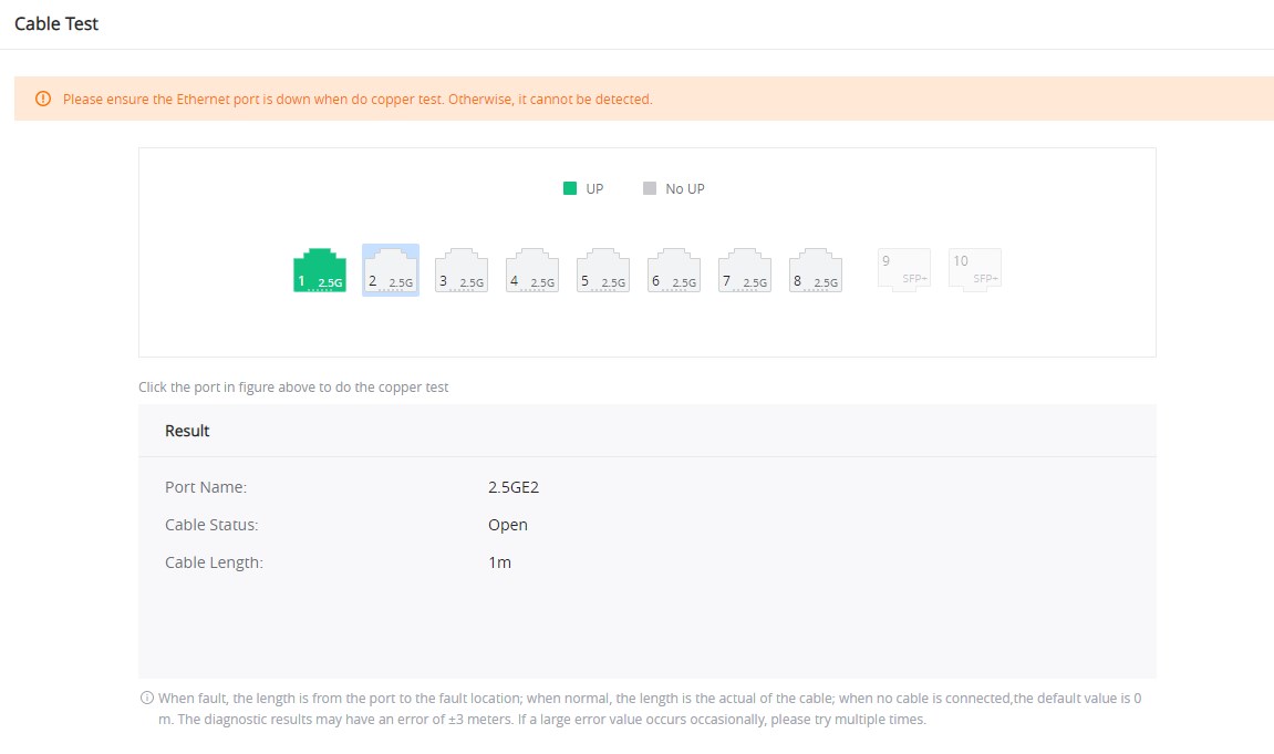
The Cable Test can detect whether the cable connected to the switch is faulty and the location of the fault. Using this function can assist in the daily engineering installation diagnosis.
Please navigate to Maintenance → Cable Test.
Loopback Detection
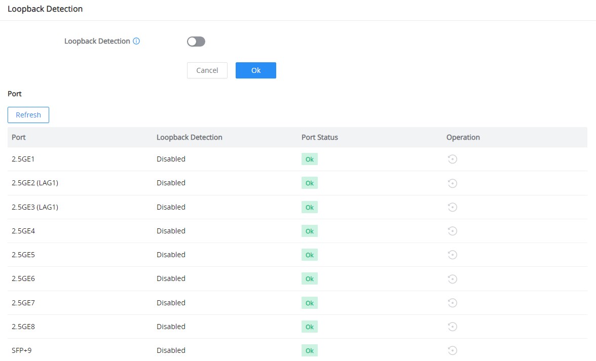
The Loopback Detection feature helps prevent self-looping on a port, which can disrupt the normal operation of the network. When loopback detection is enabled on a port, if a loop is detected, the port will automatically shut down or take appropriate measures.
Configuration:
- Navigate to Monitoring → Loopback Detection on the GWN772x switch’s web UI.
- Toggle Loopback Detection on or off.
- Click OK to save the settings.
Field | Description |
Port | The physical port on which the loopback detection settings will be applied. |
Loopback Detection | Whether loopback detection is enabled or disabled for the specific port. |
Port Status | The current operational status of the port. It shows whether the port is functioning normally (‘OK’) or if there is a fault or loop (‘Error’). |
Operation | The available actions for the port. For ports that have been disabled due to loop detection the ‘Restore’ option will appear to re-enable them. |
Loopback Detection
MAINTENANCE
Upgrade
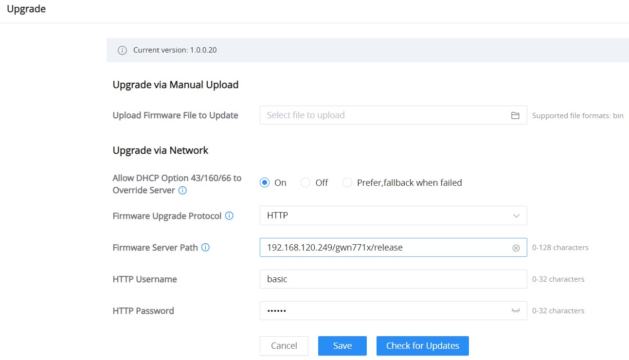
GWN772x Switches support manual upload firmware upgrade via a BIN file that can be downloaded from the Grandstream Firmware page: https://www.grandstream.com/support/firmware
Upgrade Via Network is also supported by specifying the Firmware Server Path (For example, firmware.grandstream.com).
Backup & Restore
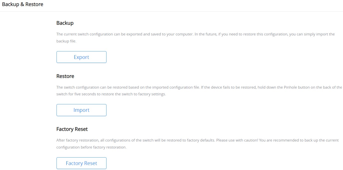
On this page, the user can back up the configuration, restore from a previously saved configuration file, or factory reset the GWN772x.
- Backup: The current switch configuration can be exported and saved to your computer. In the future, if you need to restore this configuration, you can simply import the backup file.
- Restore: The switch configuration can be restored based on the imported configuration file. If the device fails to be restored, hold down the Pinhole button on the back of the switch for five seconds to restore the switch to factory settings.
- Factory Reset: After factory restoration, all configurations of the switch will be restored to factory defaults. Please use it with caution! You are recommended to back up the current configuration before factory restoration.
Ping
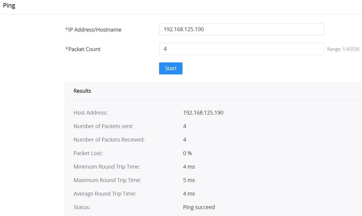
The user on this page can enter the IP Address or Hostname and then click “Start”, the results of the ping command will be shown below.
SNMP
The Simple Network Management Protocol (SNMP) feature allows network administrators to monitor and manage devices within the network. The SNMP feature can be configured to send notifications and traps to an SNMP manager, helping to ensure efficient network operations.
Global Settings – SNMP
The Global Settings tab in the SNMP section allows administrators to configure community strings for SNMPv2 operations.
To access SNMP Global Settings:
- Navigate to Maintenance → SNMP → Global Settings.
- Enable SNMP by toggling the switch to ON.
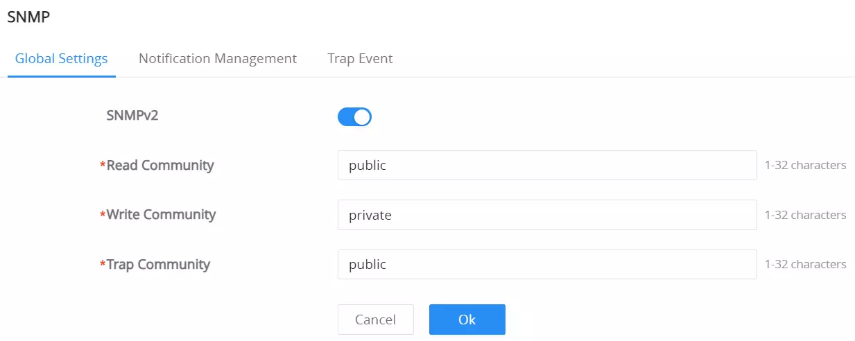
Field Name | Description | Character Limit/Range |
Read Community | Defines the community string for read-only access. | 1-32 characters |
Write Community | Defines the community string for read-write access. | 1-32 characters |
Trap Community | Defines the community string for sending SNMP traps to the manager. | 1-32 characters |
SNMP Global Settings Field Descriptions
Notification Management
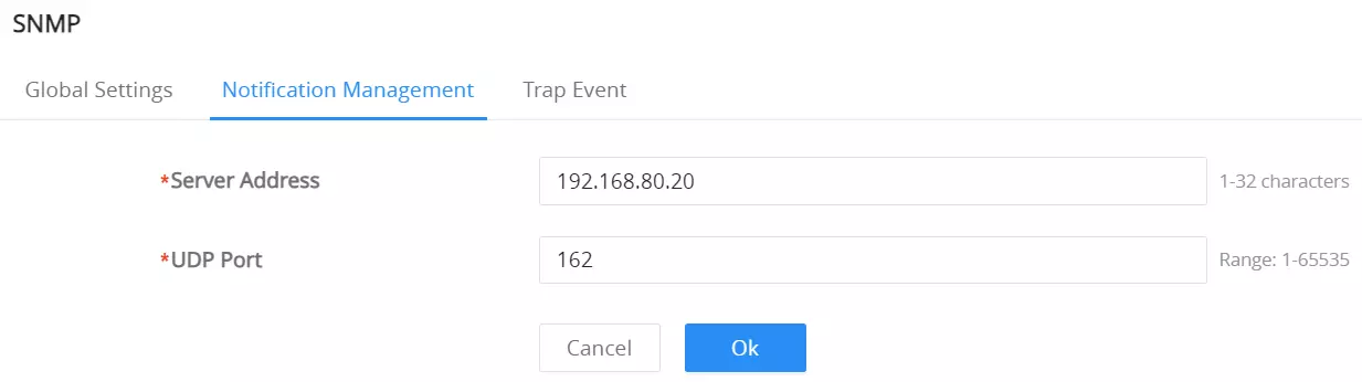
The Notification Management tab allows the configuration of the SNMP trap server and port.
To configure the trap server:
- Navigate to Maintenance → SNMP → Notification Management.
- Set the following fields:
- Server Address: Specify the IP address of the SNMP trap server.
- UDP Port: Enter the port used for SNMP trap communication (default is 162).
Trap Event
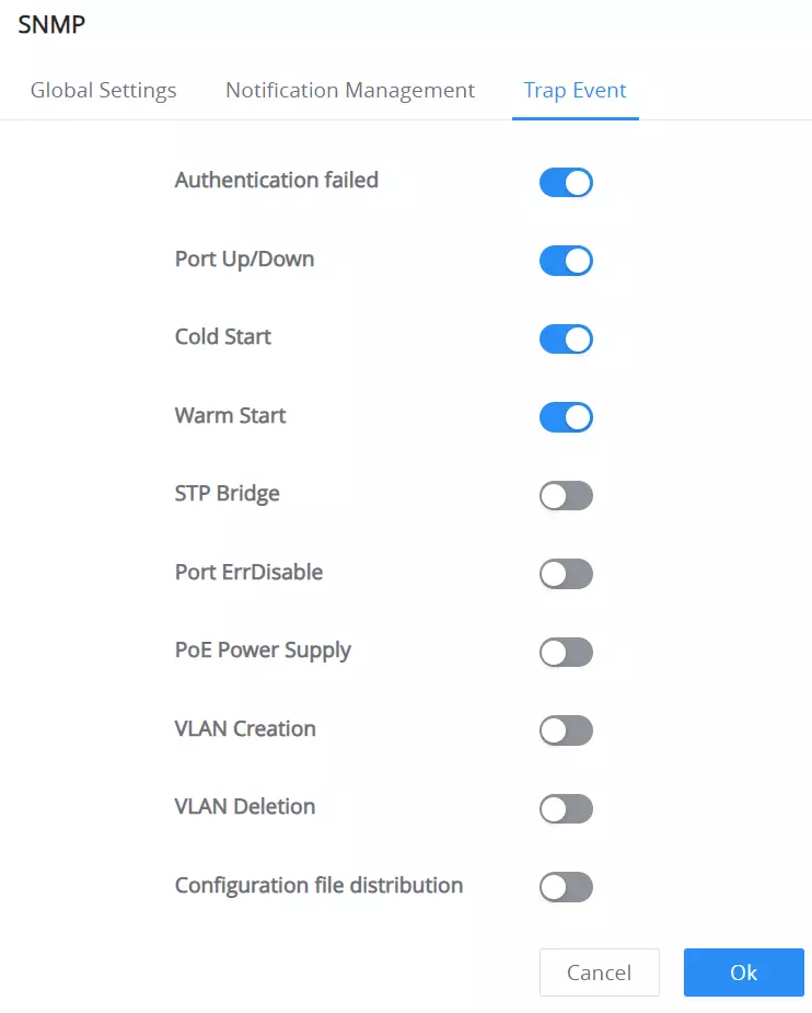
The Trap Event tab allows administrators to select the specific events for which SNMP traps should be sent to the SNMP manager.
To configure SNMP traps:
- Navigate to Maintenance → SNMP → Trap Event.
- Enable the desired trap events by toggling their switches. The available events are:
- Authentication Failed
- Port Up/Down
- Cold Start
- Warm Start
- STP Bridge
- Port ErrDisable
- PoE Power Supply
- VLAN Creation
- VLAN Deletion
- Configuration File Distribution
LLDP
The Link Layer Discovery Protocol (LLDP) allows the switch to advertise its identity, capabilities, and status to neighboring devices in the network. LLDP helps administrators efficiently monitor and manage network devices by providing detailed information about devices connected to the network.
Global Settings
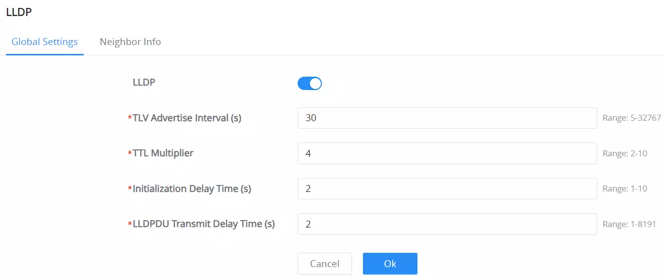
To access LLDP Global Settings:
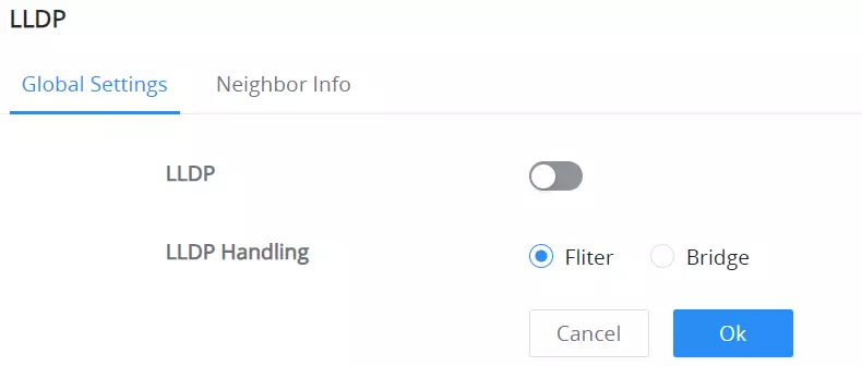
- Navigate to Maintenance → LLDP → Global Settings.
- Enable LLDP by toggling the switch to ON.
When LLDP is disabled, the system provides two handling options:
- Filter: Stops LLDP packets at the device, using LLDP only for local neighbor information.
- Bridge: Forwards LLDP packets to other devices, enabling broader network discovery.
Select the desired LLDP handling method, then click OK.
Field Name | Description | Range |
If LLDP is disabled | ||
Filter | stops LLDP packets at the device, using LLDP only for local neighbor information. | – |
Bridge | forwards LLDP packets to other devices, enabling broader network discovery. | – |
If LLDP is enabled | ||
TLV Advertise Interval (s) | Defines the interval (in seconds) at which LLDP advertisements are sent to neighboring devices. | 5 – 32767 |
TTL Multiplier | Specifies the Time-to-Live (TTL) multiplier for LLDP data units, determining their expiration time. | 2 – 10 |
Initialization Delay Time (s) | Configures the delay time before LLDP starts after being enabled. | 1 – 10 |
LLDPDU Transmit Delay Time (s) | Determines the delay between transmissions of LLDP Data Units (LLDPDU). | 1 – 8191 |
LLDP Global Settings Field Descriptions
Port Settings
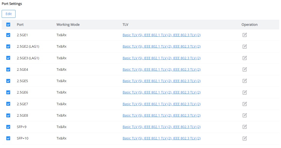
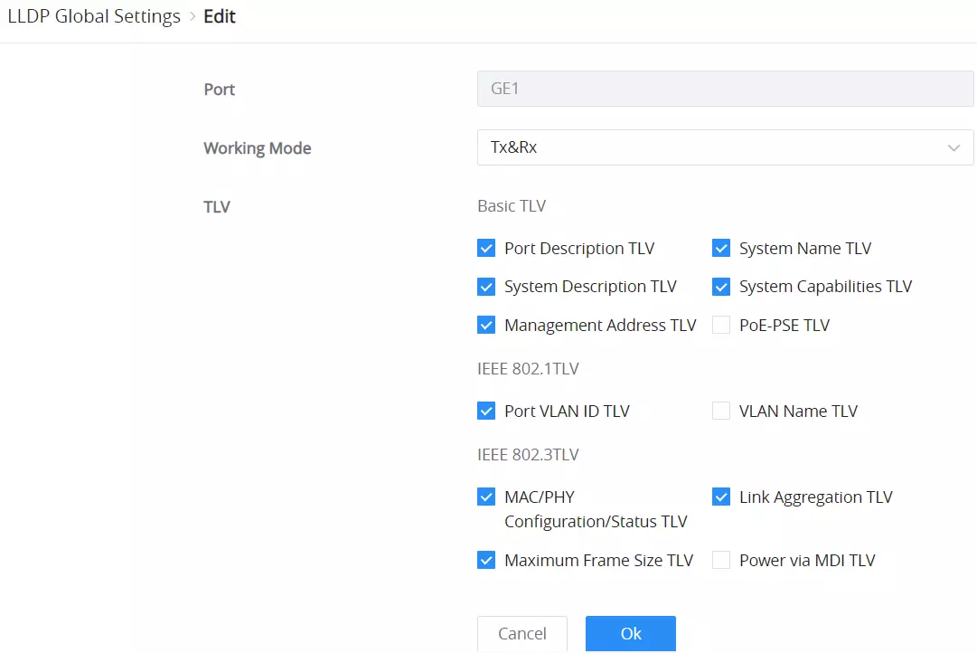
The Port Settings section allows the configuration of LLDP operation on a per-port basis. Users can specify how LLDP should behave on each port and select elements to include in the advertisements.
To configure LLDP per port:
- Under the Global Settings tab, scroll down to Port Settings.
- Click Edit next to the desired port to modify its LLDP configuration.
Field Name | Description |
Port | Specifies the port being configured. |
Working Mode | Select whether the port should
|
TLV | Select which Type-Length-Value (TLV) elements to advertise. |
LLDP Port Settings Field Descriptions
Neighbor Info
The Neighbor Info tab provides detailed information about the devices connected to the switch via LLDP. This includes the identity, chassis ID, and port information for each neighboring device.
To access Neighbor Info:
- Navigate to Maintenance → LLDP → Neighbor Info.
- The page will display the following information for each neighboring device:
- Local Port: The local port connected to the neighbor.
- Chassis ID: The chassis ID of the neighboring device.
- Neighbor Port ID: The port on the neighboring device that is connected to the switch.
- Device Name: The name of the neighboring device.
- System Description: A description of the neighboring device.
- Survival Time (TTL): The remaining time before the neighbor’s LLDP data expires.
- Click Refresh to update the information, or Delete to remove neighbor entries.

CHANGE LOG
This section documents significant changes to the GWN7721 Series user manual. Only major new features or major document updates are listed here. Minor updates for corrections or editing are not documented here.
Firmware Version 1.0.7.128
Product names: GWN7721, GWN7721P, GWN7721PE
- Added support for new model GWN7721PE.
Firmware Version 1.0.7.105
Product name: GWN7721, GWN7721P
- Added VLAN transparent transmission function for 802.1Q VLAN. [802.1Q PVID Settings]
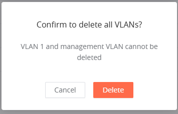
- Added prompt to notify that VLAN 1 and the Management VLAN cannot be deleted when clicking “Delete All”. [802.1Q VLAN]
- Updated LLDP to display Link Aggregation information under the IEEE 802.3 TLV section. [LLDP]
Firmware Version 1.0.1.33
Product name: GWN7721, GWN7721P
- This is the initial release.