


Overview
The VLAN Transparent Mode allows a GWN77xx switch port to accept all tagged VLAN frames (1–4094) without discarding packets that belong to VLANs not explicitly configured in the VLAN table. This means that if VLANs are already configured on the router, there is no need to configure them again on the GWN77xx switch, provided they are only meant to be forwarded. Enabling VLAN Transparent Mode on the uplink (trunk) port is sufficient to achieve this.
This feature is used on uplink or trunk ports connected to other switches or routers that carry multiple VLANs, and this ensures that traffic from unconfigured VLANs is not dropped by the switch.
In standard operation, the GWN77XX series supports up to 32 active VLANs (from VLAN ID 1–4094). VLANs outside this range are normally discarded unless VLAN transparent mode is enabled.
Understanding The Concept
When VLAN Transparent Mode is disabled:
- The switch only accepts packets belonging to configured VLANs (maximum 32).
- Packets with unknown VLAN IDs are discarded.
When VLAN Transparent Mode is enabled on a port:
- The port accepts VLAN-tagged packets (1–4094) without filtering.
- The switch then forwards these packets to the designated ports that have the VLAN transparent mode enabled.
This provides compatibility with upstream devices transmitting large VLAN ranges while maintaining the switch’s internal VLAN limits.
Configuration Scenario
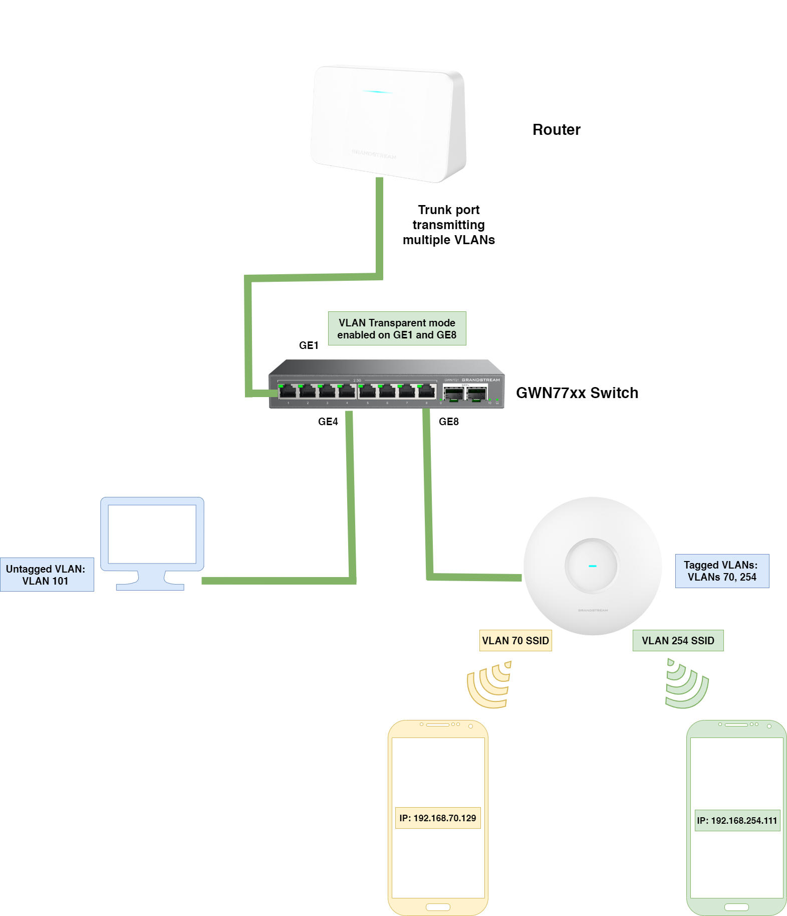
In our configuration scenario , a router transmits multiple VLANs (1–4094), including VLAN 70, 254, 101, the VLANs: 254 and 70 are not configured on the switch side.
Our goal is to allow the switch to forward packets tagged with vlan IDs 70 and 254 To the designated destination, without dropping them, the designated destination is a GWN access point that has two SSIDs:
- SSID VLAN70: Connected clients will get the IP address: 192.168.70.x
- SSID VLAN254: Connected clients will get the IP address: 192.168.254.x
We can achieve this by one important option: enabling the Transparent mode on trunk ports that are connected to uplinks and to devices that transmit VLANs; in our case it is the GWN access point.
Below is an illustration that describes the setup:
Step 1. Create VLANs on Router Side
- On the router/core switch side, go to Internet Settings – LAN Settings – VLAN
- Create the following VLAN IDs , and configure their IP interfaces respectively:
- VLAN 70: 192.168.70.0/24
- VLAN 254: 192.168.254.0/24
- VLAN 101: 192.168.101.0/24
- Default VLAN (VLAN 1): This is already created by default.
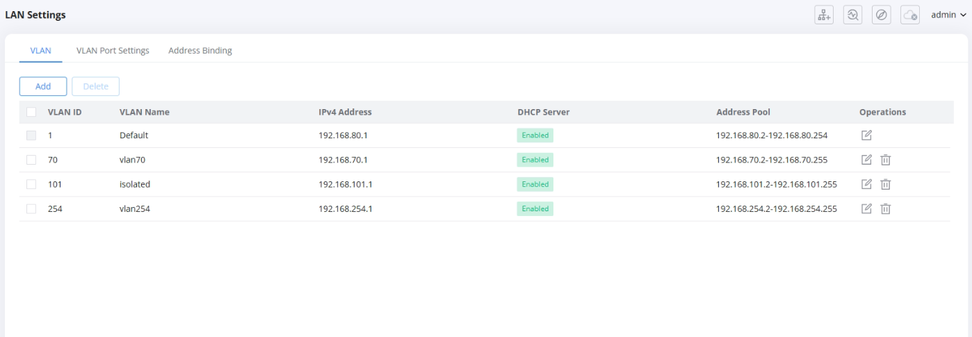
- In total we will have 4 different VLANs each VLAN has its respective IP interface, and all VLANs are passed through the trunk port connected to the GWN77xx switch.
Step 2. Enable VLAN Transparent Mode
On the GWN77xx switch, carry on the following configuration:
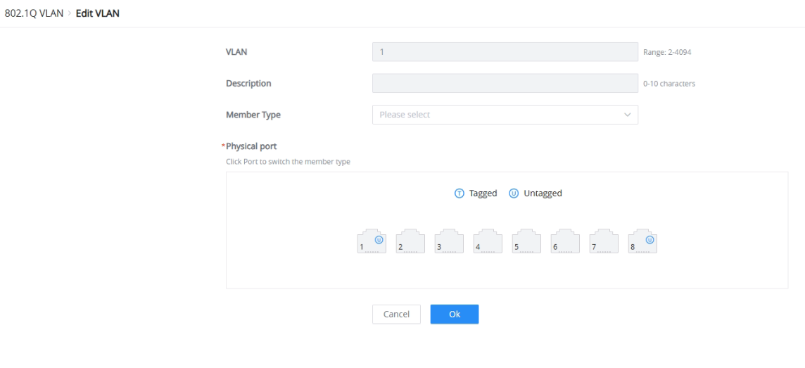
- Under VLAN – 802.11Q VLAN:
- Create VLAN ID 101, then select ports GE2 to GE7 and set them to be untagged ports. These ports will be used to connect devices that will automatically be assigned VLAN ID 101
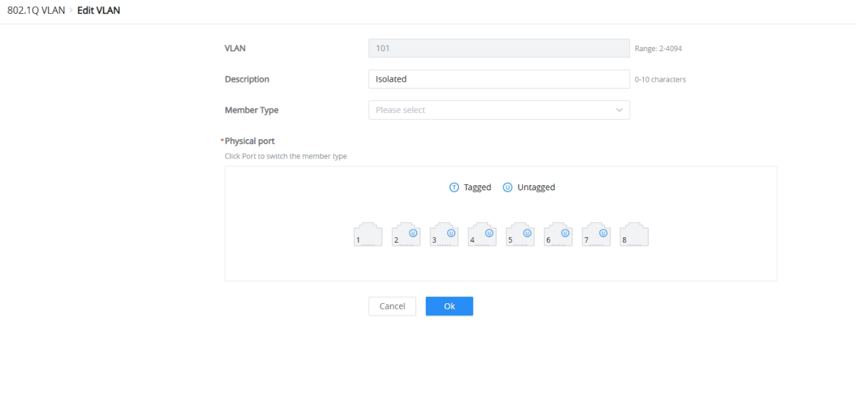
- Change the default VLAN ports so that they contain only ports GE1 and GE8. These ports will be used to connect uplink ports and trunk ports, such as the one connected to the GWN Access point.
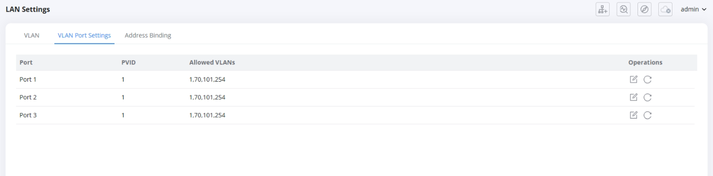
- Under 802.1Q PVID Settings: For GE1, GE8, enable VLAN transparent mode, and keep the PVID set to 1 ( the default VLAN).
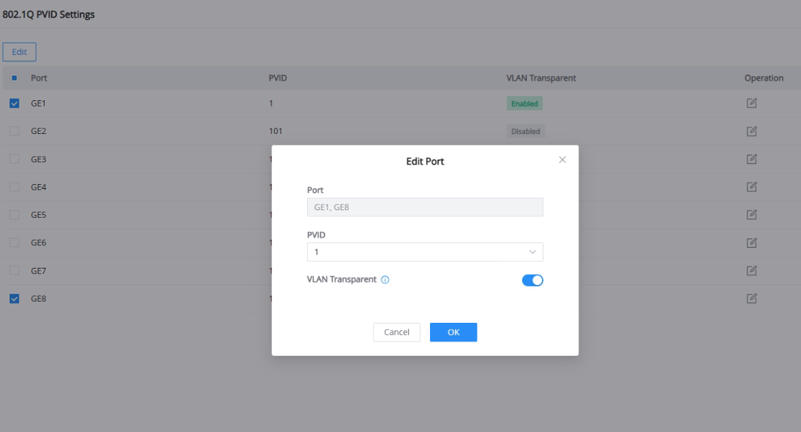
With all of this configured, we have successfully achieved our goal of allowing non-configured VLANs on the switch side to be forwarded to their designated destinations by passing through the trunk port of the GWN77xx switch.
Step 3. Configure the GWN Access Point
Now that we have our switch configured to allow transparent VLANs, on the Access Point side, we need to create different SSIDs for users to connect to. Each SSID is mapped to a specific VLAN tag, so when a customer connects to the SSID named “VLAN 70,” he gets placed in VLAN 70.
We will create two SSIDs:
- VLAN 70: This will allow devices connected to this SSID to get an IP address of 192.168.70.x
- VLAN 254: This will allow devices connected to this SSID to get an IP address of 192.168.254.x
Important information: Without VLAN transparent enabled on the trunk port connected from the GWN77xx switch to the GWN access point, the packets coming from the router and tagged with VLAN ID 70, AND 254 will not be forwarded to the access point, and will be discarded at the switch level, at this stage we see the important role VLAN transparent mode plays in our network.
Let’s follow the below configuration:
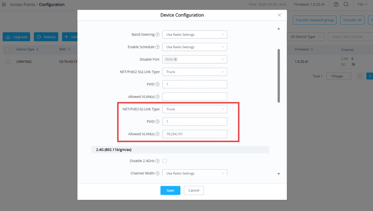
- Open the Web UI of the GWN Access point, go to Access Points – Configuration
- On the NET/PoE port connected to the GWN77xx switch, make sure to set that port to “Trunk,” set the PVID to 1 (default VLAN), and add the allowed VLANs by entering their VLAN IDs: 70, 254, and 101.
- Click Save and apply changes.
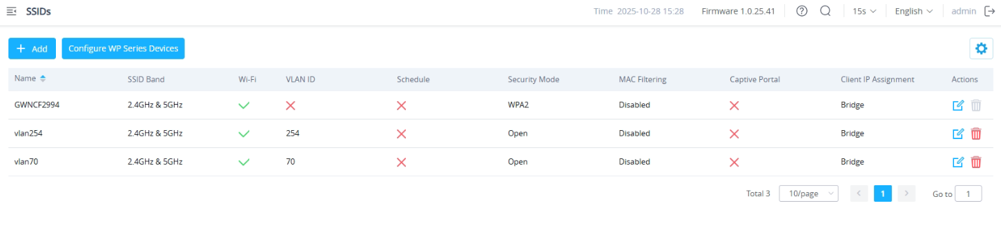
- Now we need to create SSIDs mapped to specific VLANs so that when a client connects to one of the SSIDs, they are automatically placed in their respective network.
- SSID1: vlan254
- SSID2: vlan70
- Go to the SSIDs page, click on add, name the SSID: vlan254
- Enable SSID
- Enable the VLAN option, and then set the VLAN ID to 254. For easy testing, we will set the security mode to open, so that devices can automatically connect and get an IP address.
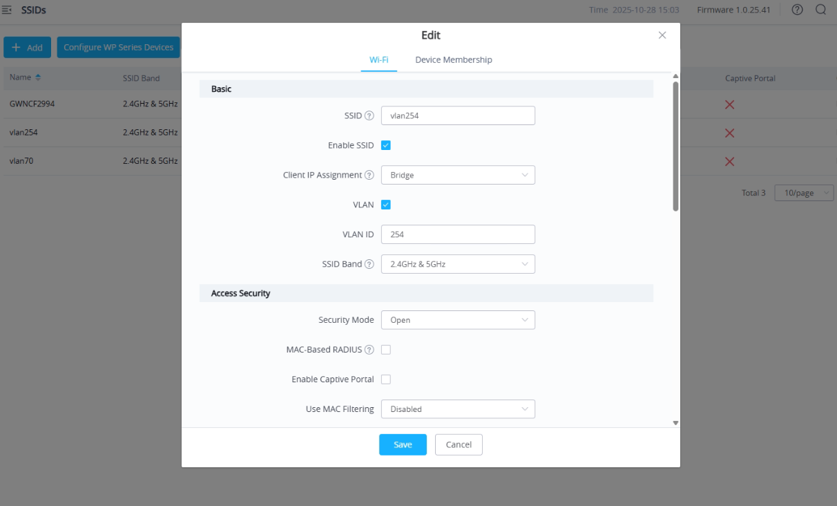
- Under Device Membership, Add the GWN Access point to the SSID.
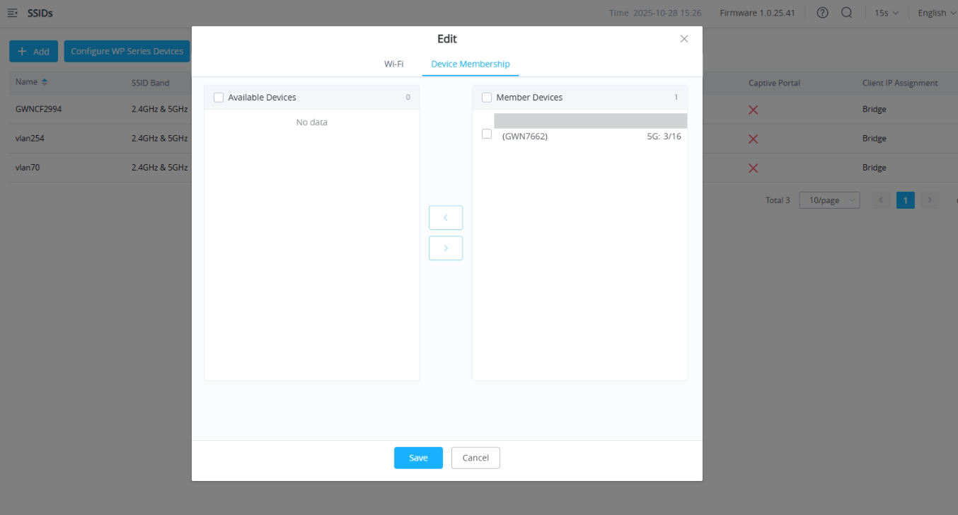
In the same way, create the second SSID for VLAN 70 and name it “VLAN70.” In total, we will have the default SSID plus two additional SSIDs, allowing users to connect to different networks depending on which SSID they join.
Step 4. Verification & Results
With the above example configured :
- Devices connected to VLAN 70 will be assigned an IP address in the 192.168.70.x range, for example: 192.168.70.129
- Devices connected to VLAN 254 will be assigned an IP address in the 192.168.254.x range, for example: 192.168.254.111
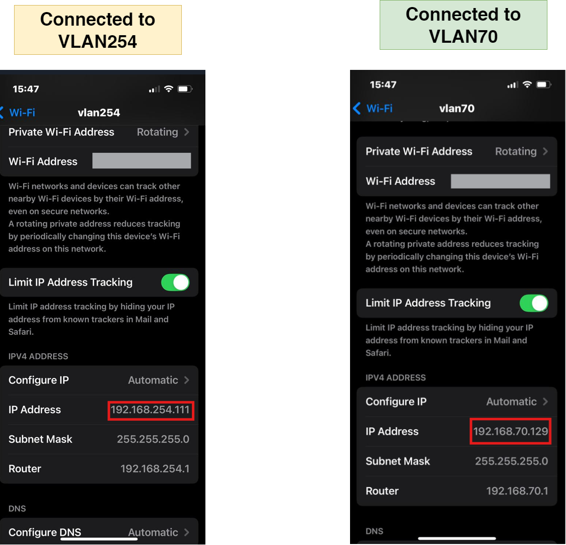
This is made possible by enabling VLAN Transparent mode on the trunk port that connects the GWN77xx switch to the GWN Access Point. Although VLANs 70 and 254 were not created on the switch and are therefore not recognized by it, the switch still forwards packets tagged with those VLAN IDs between the router and the Access Point through the GWN77xx switch.
Supported Devices
| Model | Minimum Firmware Required |
|---|---|
| GWN7711 | 1.0.7.9+ |
| GWN7711P | 1.0.7.9+ |
| GWN7710R | 1.0.7.9+ |
| GWN7721 | 1.0.7.105+ |
| GWN7721P | 1.0.7.105+ |
| GWN7721PE | 1.0.7.128+ |