


Overview
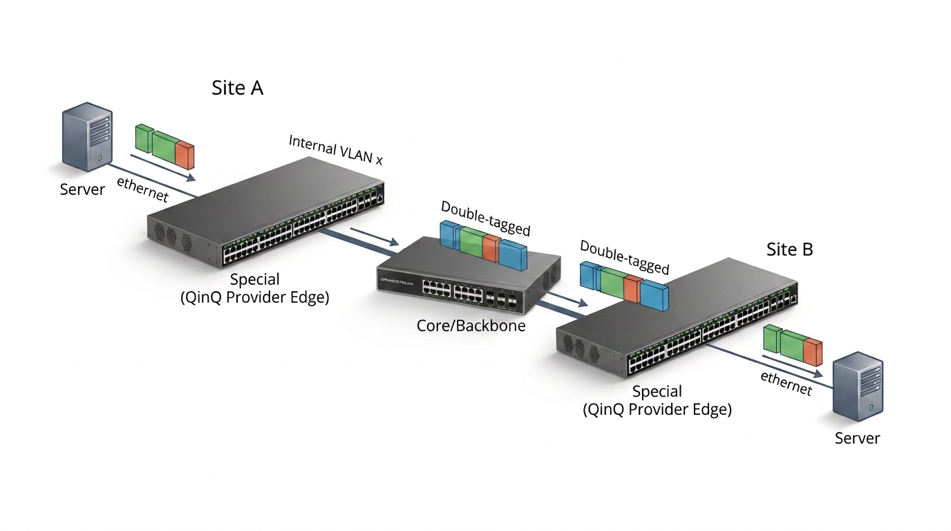
Port QinQ (also known as Basic QinQ, Port-based QinQ, or IEEE 802.1ad QinQ) is a Layer 2 tunneling technology that allows customer VLANs (CVLANs) to be transparently transported across a service provider or enterprise backbone by encapsulating them with an additional Service VLAN (SVLAN), also referred to as a provider VLAN.
Instead of replacing the customer’s VLAN tag, a QinQ port adds a second tag to create a double-tagged Ethernet frame.
Simply put, frames entering a QinQ port carry two VLAN tags: the original inner Customer VLAN (CVLAN) tag and an outer Service VLAN (SVLAN) tag. The backbone forwards traffic by the outer tag, which prevents conflicts between customers that use the same CVLAN IDs.
How Port QinQ Works
A QinQ port operates according to the IEEE 802.1ad standard.
The forwarding process is as follows:
- A user device sends traffic containing its original customer VLAN (CVLAN).
- The switch receives the traffic on a Tunnel (QinQ) port.
- The switch automatically adds a predefined outer VLAN tag (SVLAN).
- The double-tagged packet is forwarded across the backbone network.
- The remote switch receives the packet.
- Before forwarding traffic toward the destination network, the outer SVLAN tag is removed.
- The original customer VLAN is preserved throughout the process.
This mechanism extends Layer 2 connectivity between geographically separated sites while conserving VLAN IDs in the backbone. Traffic keeps its original CVLAN from Site A to Site B, while the backbone uses the added SVLAN to transport and isolate it.
Before You Begin
- Confirm that both switches support QinQ and use the same TPID across the QinQ path. The Web UI example in this guide uses TPID 0x8100.
- Create the required SVLANs on both switches and allow them on every backbone trunk between the sites.
- Ensure that customer traffic is already tagged with the intended CVLAN before it enters a QinQ tunnel port.
- Account for the additional 4-byte outer VLAN tag when validating the end-to-end MTU.
Configuration Example 1
Network Scenario
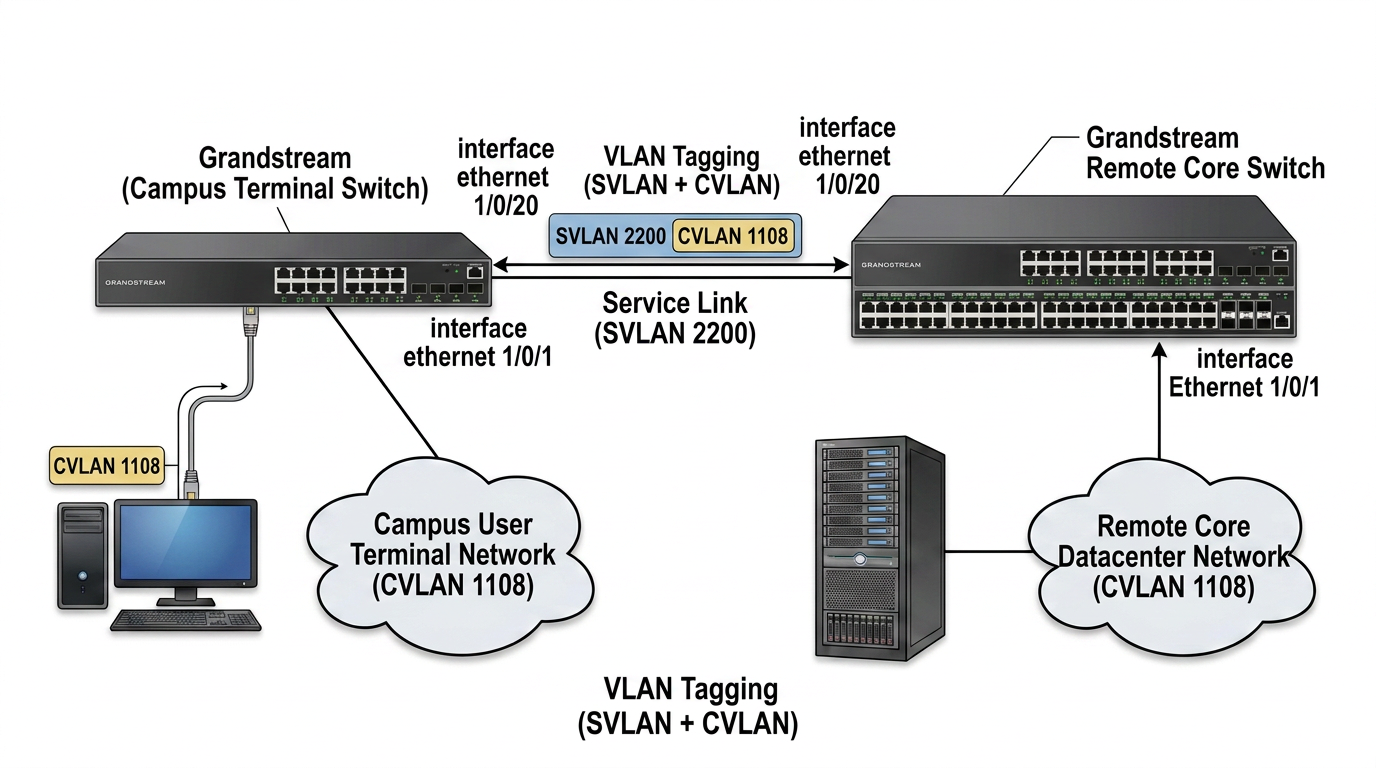
In this example:
- PC1 acts as a campus user terminal.
- The terminal must establish Layer 2 connectivity with a remote core switch.
- The terminal belongs to Customer VLAN (CVLAN) 1108.
- The backbone network uses Service VLAN (SVLAN) 2200.
- The objective is to minimize VLAN consumption within the backbone while maintaining transparent Layer 2 communication.
Network Topology
Configuration Strategy
Configure both switches so that the customer-facing ports add or remove the SVLAN and the backbone trunk carries that SVLAN between the sites.
Step 1 Configure the User Facing Tunnel Port
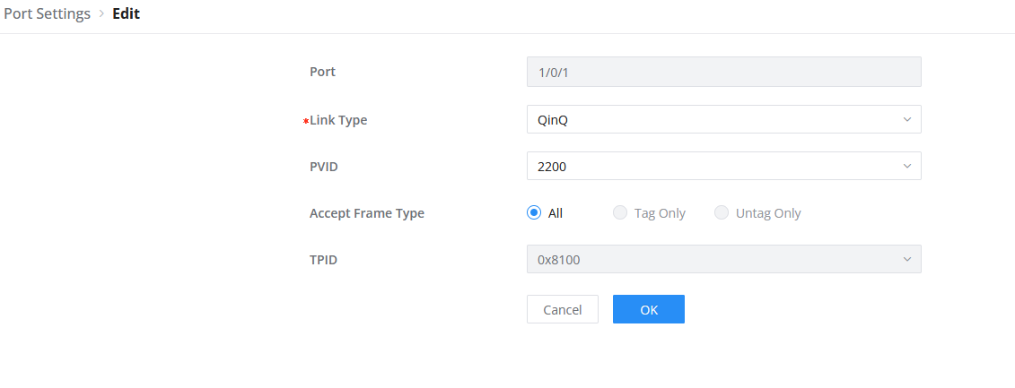
Configure the interface connected to the customer network as a Tunnel (QinQ) port.
When a frame carrying CVLAN 1108 enters this port, the switch adds outer SVLAN 2200.
Step 2 Configure the Backbone Trunk
Configure the interconnection interfaces between Device A and Device B as trunk ports. This will allow Service VLAN 2200 across the trunk so double-tagged traffic can traverse the backbone.
Step 3 Configure the Remote Tunnel Port
On Device B, configure the interface connected to the destination network as a QinQ port.
When traffic exits this interface, the switch removes the outer SVLAN tag and preserves the original CVLAN 1108 tag.
CLI Configuration
Configure Device A
DeviceA# configure
DeviceA(config)# vlan 2200
DeviceA(config-vlan)# exit
DeviceA(config)# interface Ethernet 1/0/1
DeviceA(config-if)# switchport mode tunnel
DeviceA(config-if)# switchport tunnel vlan 2200
DeviceA(config-if)# exit
DeviceA(config)# interface Ethernet 1/0/20
DeviceA(config-if)# switchport mode trunk
DeviceA(config-if)# switchport trunk allowed vlan add 2200
Ethernet 1/0/1 adds SVLAN 2200 to customer traffic, and trunk port Ethernet 1/0/20 carries SVLAN 2200 toward Device B.
Configure Device B
DeviceB# configure
DeviceB(config)# vlan 2200
DeviceB(config-vlan)# exit
DeviceB(config)# interface Ethernet 1/0/1
DeviceB(config-if)# switchport mode tunnel
DeviceB(config-if)# switchport tunnel vlan 2200
DeviceB(config-if)# exit
DeviceB(config)# interface Ethernet 1/0/20
DeviceB(config-if)# switchport mode trunk
DeviceB(config-if)# switchport trunk allowed vlan add 2200
Trunk port Ethernet 1/0/20 receives SVLAN 2200 from Device A. When traffic exits customer-facing port Ethernet 1/0/1, Device B removes the outer SVLAN and forwards the frame with its original CVLAN 1108 tag.
Verifying the Configuration
Verify the Tunnel Port Configuration
Run:
show running-config interfaces Ethernet 1/0/1Expected output:
interface eth1/0/1
 switchport mode tunnel
 switchport tunnel vlan 2200
This confirms that the interface is operating in Tunnel mode and is using Service VLAN 2200.
Verify MAC Address Learning
Run the following command on Device A:
show mac address-table interfaces Ethernet 1/0/1The MAC address of the connected user device should be learned under Service VLAN 2200.
Verify Cross Device MAC Learning
Run the following command on Device B:
show mac address-table interfaces Ethernet 1/0/1The MAC address should also appear under Service VLAN 2200, confirming that the tagged traffic is traversing the backbone successfully.
Verify End to End Connectivity
Perform a ping test between the user terminal and the remote core switch.
Successful replies confirm transparent Layer 2 communication through the QinQ tunnel.
Configuration Example 2
Network Scenario for Example 2
In this example, Device A and Device B connect two independent customer networks that are geographically separated and interconnected through a shared backbone.
The backbone uses separate Service VLANs to transport traffic for each customer network.
- User Network A uses Customer VLANs 10–50.
- User Network B uses Customer VLANs 20–60.
- Service VLAN 100 is assigned to User Network A.
- Service VLAN 200 is assigned to User Network B.
The CVLAN ranges overlap from 20 through 50. This is intentional: the different outer SVLANs keep User Networks A and B isolated even when they use the same inner VLAN IDs.
This configuration allows:
- Communication between User Network A sites.
- Communication between User Network B sites.
- Complete isolation between User Network A and User Network B.
Configuration Procedure
Apply the following configuration on both Device A and Device B.
Step 1 Create the Service VLANs
Device# configure
Device(config)# vlan 100,200
Device(config-vlan)# exit
SVLAN 100 transports User Network A traffic, while SVLAN 200 transports User Network B traffic.
Step 2 Configure the Customer Facing Tunnel Ports
Device(config)# interface Ethernet 1/0/1
Device(config-if)# switchport mode tunnel
Device(config-if)# switchport tunnel vlan 100
Device(config-if)# exit
Device(config)# interface Ethernet 1/0/2
Device(config-if)# switchport mode tunnel
Device(config-if)# switchport tunnel vlan 200- Ethernet 1/0/1 maps User Network A traffic to SVLAN 100.
- Ethernet 1/0/2 maps User Network B traffic to SVLAN 200.
Step 3 Configure the Backbone Trunk
Device(config)# interface Ethernet 1/0/3
Device(config-if)# switchport mode trunk
Device(config-if)# switchport trunk allowed vlan add 100,200
The trunk carries both SVLANs between the switches while keeping User Networks A and B isolated.
Verification
After completing the configuration, perform the following tests.
Test 1 User Network A Connectivity
Hosts within User Network A behind Device A should successfully communicate with hosts in the same VLAN behind Device B.
Expected Result
Communication succeeds.
Test 2 User Network B Connectivity
Hosts within User Network B behind Device A should successfully communicate with hosts in the same VLAN behind Device B.
Expected Result
Communication succeeds.
Test 3 Network Isolation
Use an overlapping CVLAN ID, such as VLAN 20, to test between User Network A and User Network B. The hosts should not communicate because the traffic is separated by SVLAN 100 and SVLAN 200.
Expected Result
Communication fails.
This confirms that the Service VLANs maintain isolation between the two customer networks.
Configuration Summary
| Configuration Element | Example 1 | Example 2 |
|---|---|---|
| Customer VLAN (CVLAN) | 1108 | VLANs 10–50 and 20–60 |
| Service VLAN (SVLAN) | 2200 | VLAN 100 and VLAN 200 |
| Tunnel Ports | Ethernet 1/0/1 | Ethernet 1/0/1 and Ethernet 1/0/2 |
| Backbone Trunk | Ethernet 1/0/20 | Ethernet 1/0/3 |
| Verification | Running configuration, MAC learning, Ping | Connectivity and isolation tests |
Supported Devices
Device Name | Supported | Firmware Required |
GWN7801 | Yes | 1.0.3.19 or higher |
GWN7801P | Yes | 1.0.3.19 or higher |
GWN7802 | Yes | 1.0.3.19 or higher |
GWN7802P | Yes | 1.0.3.19 or higher |
GWN7803 | Yes | 1.0.3.19 or higher |
GWN7803P | Yes | 1.0.3.19 or higher |
GWN7811 | Yes | 1.0.1.8 or higher |
GWN7811P | Yes | 1.0.1.8 or higher |
GWN7812P | Yes | 1.0.1.8 or higher |
GWN7813 | Yes | 1.0.1.8 or higher |
GWN7813P | Yes | 1.0.1.8 or higher |
GWN7806 | Yes | 1.0.1.14 or higher |
GWN7806P | Yes | 1.0.1.14 or higher |
GWN7816 | Yes | 1.0.3.8 or higher |
GWN7816P | Yes | 1.0.3.8 or higher |
GWN7830 | Yes | 1.0.3.3 or higher |
GWN7831 | Yes | 1.0.3.3 or higher |
GWN7832 | Yes | 1.0.3.3 or higher |
GWN7801P Pro | Yes | 1.0.15.211 or higher |
GWN7802P Pro | Yes | 1.0.15.211 or higher |
GWN7803 Pro | Yes | 1.0.15.211 or higher |
GWN7803PL Pro | Yes | 1.0.15.211 or higher |
GWN7803PH Pro | Yes | 1.0.15.211 or higher |
GWN7806PL Pro | Yes | 1.0.15.211 or higher |
GWN7806PH Pro | Yes | 1.0.15.211 or higher |