
OVERVIEW
OSPF stands for Open Shortest Path First, it’s a routing protocol and uses a link-state routing algorithm, in other words, it collects information about the state of each link in the network to build an overall map of the whole network topology. OSPF is an interior gateway protocol (IGP) same as RIP (Routing Information Protocol), it’s a protocol based on distance vector algorithms. OSPF has many advantages over other routing protocols, such as RIP.
Some Advantages of OSPF protocol:
- OSPF can perform route summarization, which reduces the size of the routing table and improves scalability.
- OSPF supports IPv4 and IPv6.
- OSPF can split the network into areas, which are logical groups of routers that share the same link state information. This reduces the amount of routing information that needs to be exchanged and processed by each router.
- OSPF can use authentication to secure the exchange of routing information between routers.
- OSPF can deal with variable-length subnet masks (VLSM), which allows for more efficient use of IP addresses and network design.
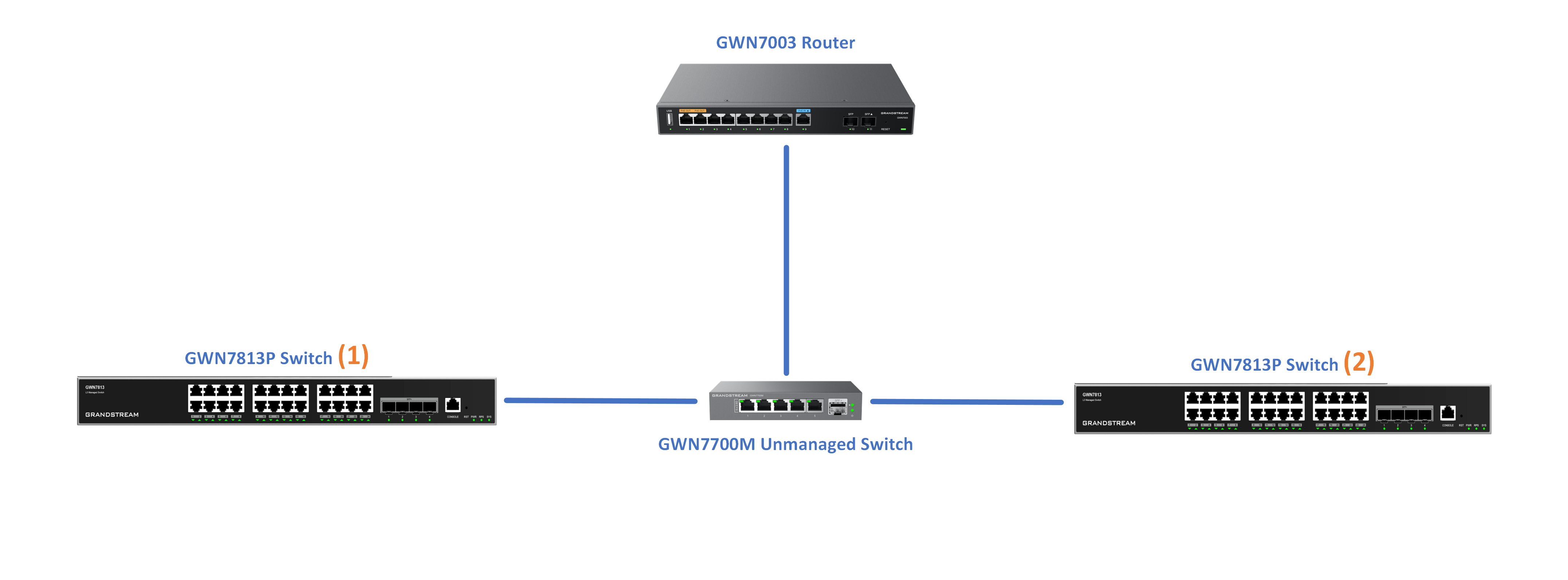
In this example, we will be using two GWN781x(P) switches directly connected (neighbors) and a router serving as a DHCP server. Please refer to the figure below:
CONFIGURATION
Step 1:
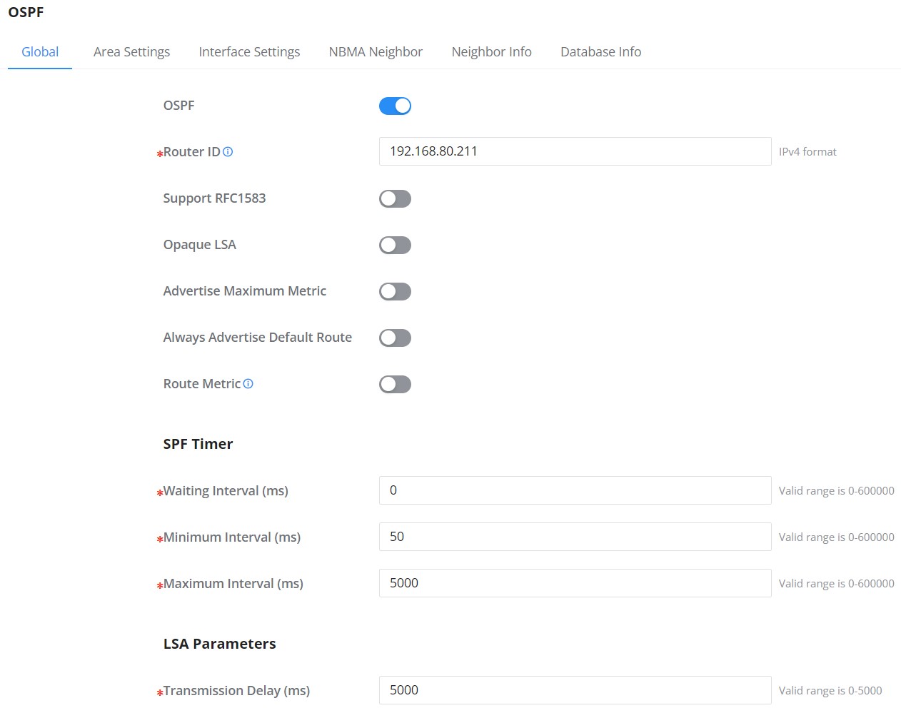
To start using OSPF, please navigate to Web UI → Routing → OSPF:
- Toggle ON OSPF and enter the Router ID (it can be any IPv4 address) then scroll down to the bottom of the page and click the “OK” button, please refer to the figure below:
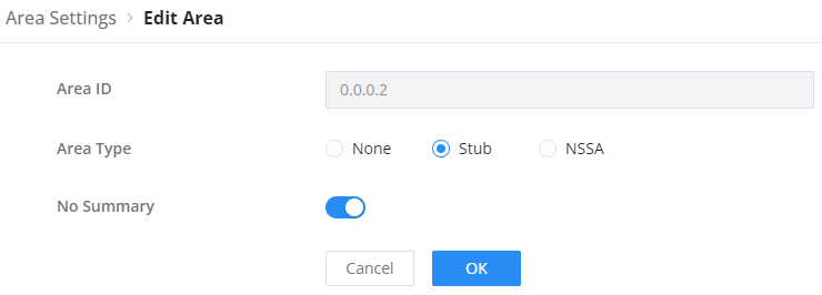
- Adding a new area to the switch can be performed only using CLI, please refer to the corresponding command in the following section. Once, a new area is added, the user can modify the type by clicking on the edit icon.
- Repeat the same steps on the other switches.
- Enter the switch’s global configuration mode by entering the command below.
GWN7813P# config- Then enable OSPF in the switch by using the command below
GWN7813P(config)# router ospf- Set a router ID for the switch, this ID is used purely to identify the switch with the OSPF configuration. The ID takes the format of IPv4 format. To set the router ID, please enter the command below.
GWN7813P(config-ospf-router)# router-id 1.1.1.1- By default, the switch is set with the area ID 0, which is the backbone area. This area cannot be set as a Standard area, Stub area, Totally Stubby area, or Not So Stubby area. In this example, we’re setting the switch to a stub area 1 with no summary area type, also known as the Totally Stubby area.
GWN7813P(config-ospf-router)# area 1 stub no-summary- Repeat the same steps on the other switches while considering giving each switch a unique router ID, otherwise OSPF might not work as intended or not work at all.
Step 2:
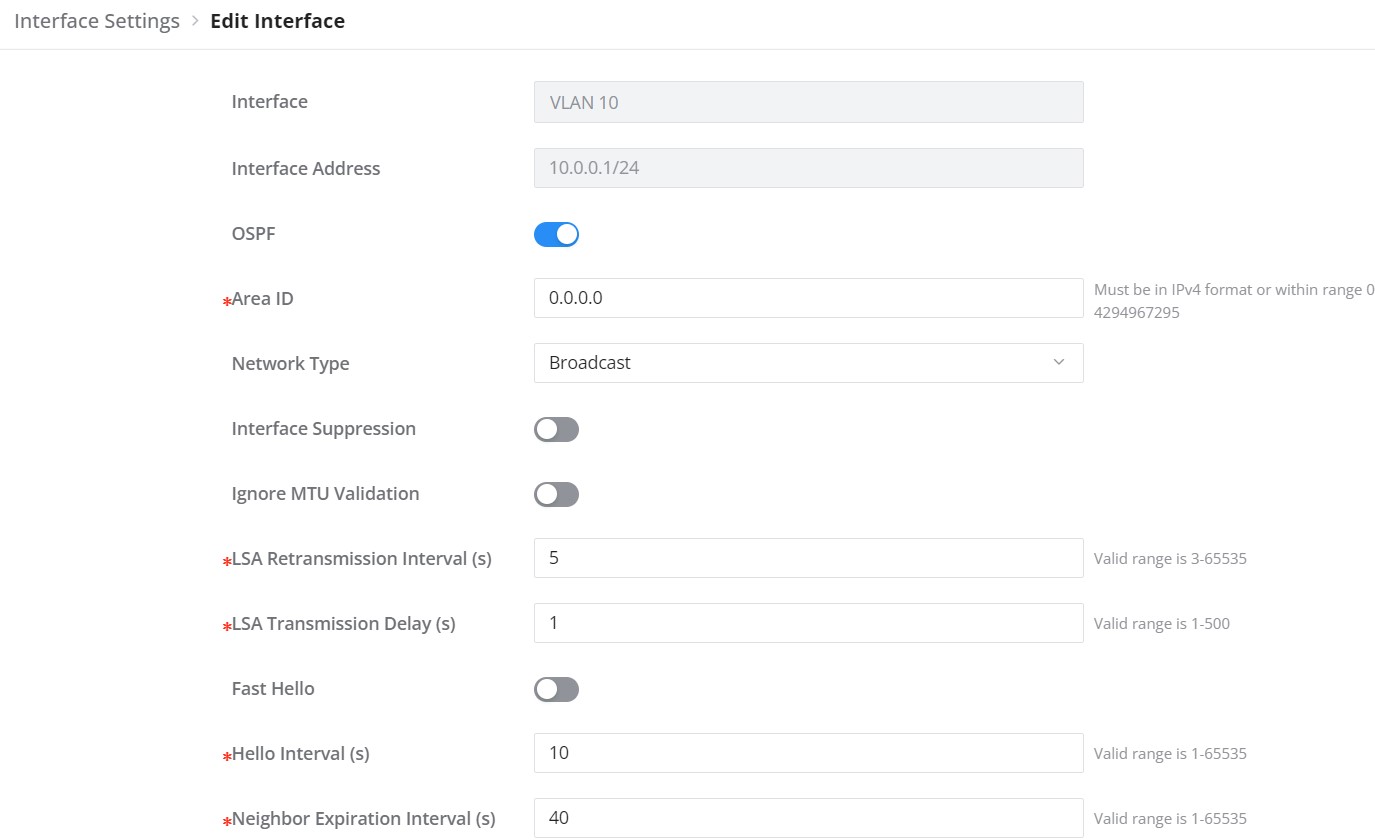
On the Interface Settings tab, click on the “Edit” icon to enable the VLAN IP Interface.
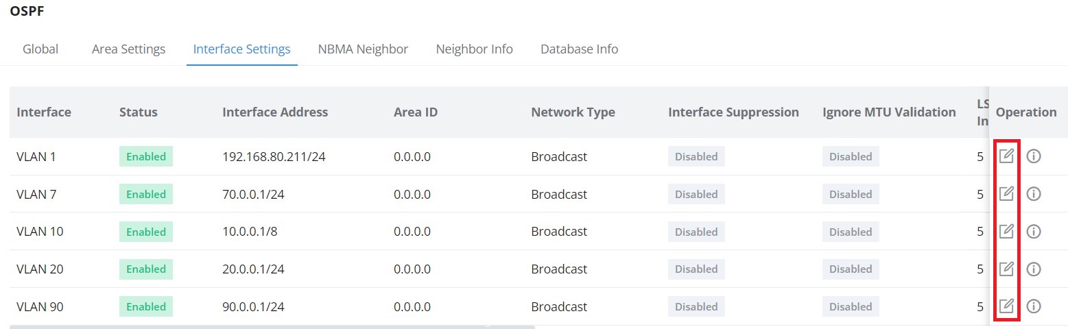
Toggle ON the OSPF on the selected interface then scroll down and click on “OK” button.
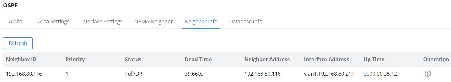
Please do the same steps on the second switch, then on the Neighbor Info tab, click on the “refresh” button for the adjacent (directly connected) switches to appear.
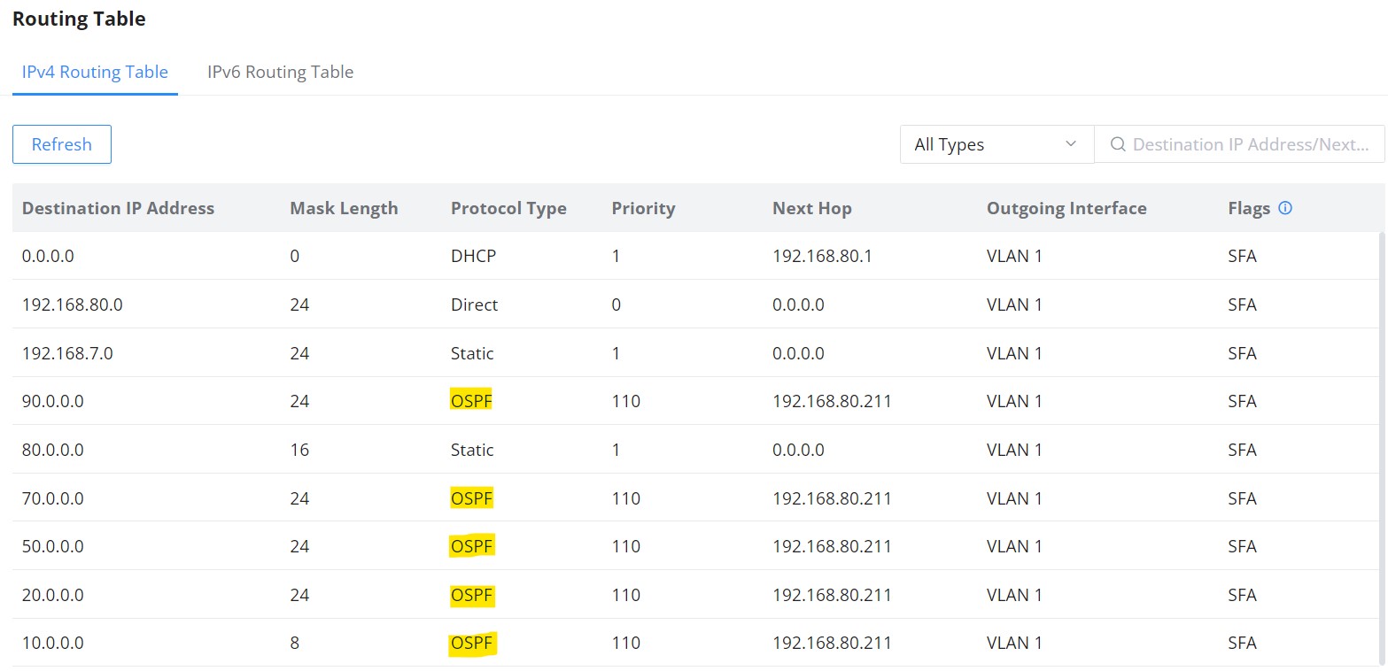
Navigate to the Routing table Web UI → Routing → Routing table to confirm that the routing table contains routes to the previously created VLAN IP Interfaces on the other switch. Please refer to the figure below:
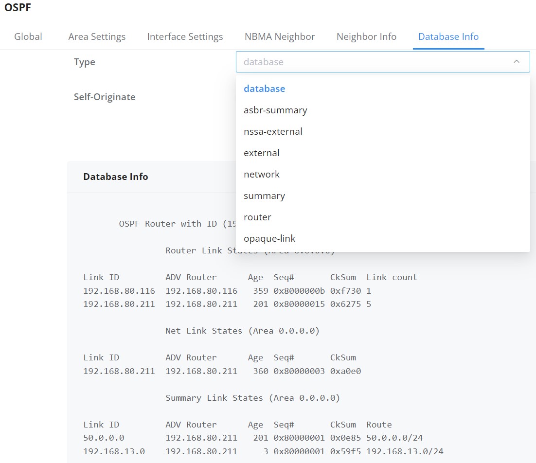
To check the LSDB (Link State DataBase), click on the Database Info tab, select the type (database) then click on the “Query” Button to see the Database info which is a list of all LSA (Link State Advertisements) that the OSPF routers use to get information about other routers running OSPF protocol and that is what helps to populate the routing table for the best route to each destination.
- From the switch’s global configuration mode, please enter the following command to enter the VLAN interface setting. In this example, we are using VLAN ID 20.
GWN7813P(config)# int vlan 20- Then enable OSPF in the VLAN interface and specify the area to which this interface belongs.
GWN7813P(config-if)# ip ospf area 1- Repeat steps 1 and 2 on the other switches
- Check the OSPF information on one of the switches.
GWN7813P# show ip ospf routeSUPPORTED DEVICES
The table below lists all the devices which this guide applies to with the respective minimum firmware version of each model.
Supported Models | Minimum Firmware Version |
GWN7811(P) | 1.0.1.8 |
GWN7812P | |
GWN7813P | |
GWN7816(P) | 1.0.3.8 |
GWN7830 | 1.0.3.1 |
GWN7831 | 1.0.3.1 |
GWN7832 | 1.0.3.1 |