Overview
MSTP (Multiple Spanning Tree Protocol) is a network protocol used to prevent loops and provide efficient load balancing in Ethernet networks. It is an enhancement of the standard Spanning Tree Protocol (STP) and its Rapid Spanning Tree Protocol (RSTP).
MSTP is commonly used in larger enterprise networks where multiple VLANs and complex network topologies exist. It provides flexibility, scalability, and improved network performance by allowing efficient load balancing and loop prevention through the use of multiple spanning trees.
MSTP produces numerous spanning trees that operate autonomously, enabling the distribution of network traffic across various VLANs. This approach facilitates load balancing without the potential for broadcast storms.
MSTP vs STP vs RSTP
STP (Spanning Tree Protocol) prevents loops in Ethernet networks by blocking redundant paths.
RSTP (Rapid Spanning Tree Protocol) is an enhancement over STP, offering faster convergence times during network changes.
MSTP (Multiple Spanning Tree Protocol) extends RSTP by allowing multiple independent spanning trees within a network, providing better resource utilization and isolation between segments.
STP is the original protocol, RSTP improves upon it, and MSTP adds support for multiple trees in complex networks.
Configuration Example
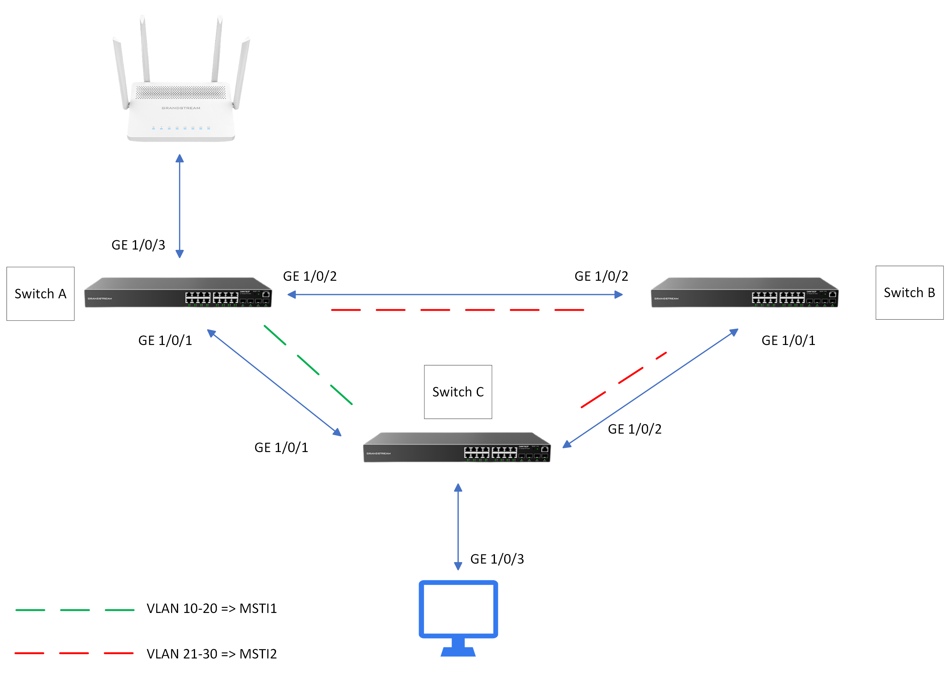
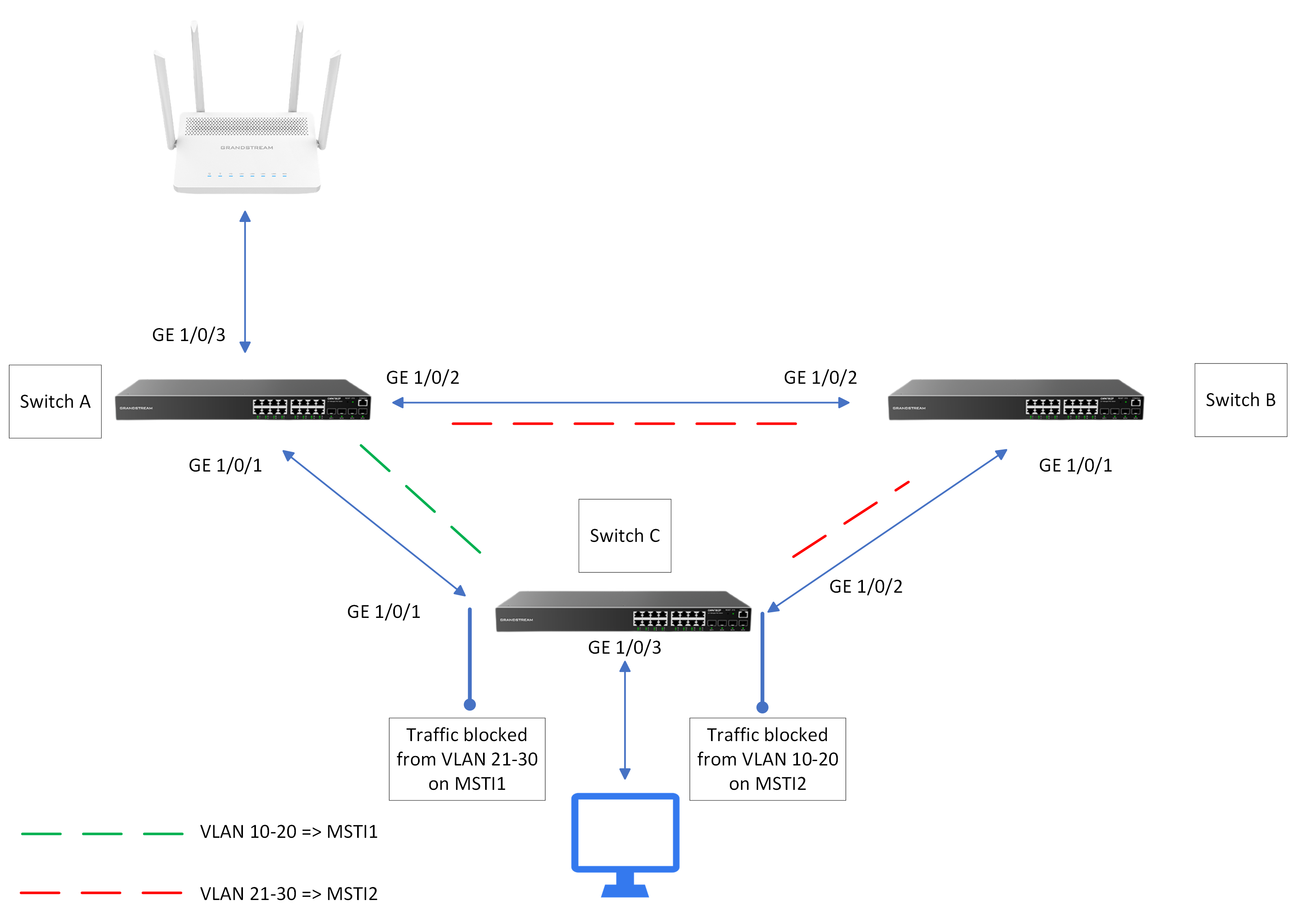
On this section of the guide, we will configure Multiple Spanning Tree Protocol on three GWN78xx switches.
In the above example, switch C handles incoming traffic from VLANs 10 to 30. Traffic originating from VLANs 10 to 20 is transmitted via the GE1/0/1 interface, while traffic from VLANs 21 to 30 is sent through the GE1/0/2 interface.
MSTP configuration Summary
After accessing the Web UI of the three switches, follow the below steps :
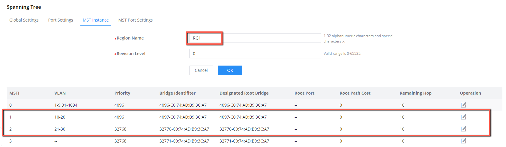
- Set the name of the MST region to RG1.
- Map VLANs 10 through 20 to MSTI 1, and VLANs 21 through 30 to MSTI 2
- Activate the configuration of the MST region.
- Configure Switch A as the root bridge and switch B as the secondary root bridge in MSTI1, and configure Switch B as the root bridge and Switch A as the secondary root bridge in MSTI2
- In MSTI 1, configure GE1/0/2 on Switch C as the blocked port. in MSTI2, Configure GE1/0/1 on Switch C as the blocked port. You can configure path costs of ports to specify the blocked ports.
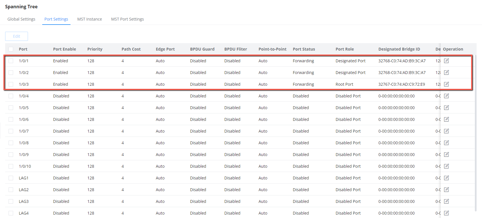
- Disable STP on the ports that do not participate in STP Calculation.
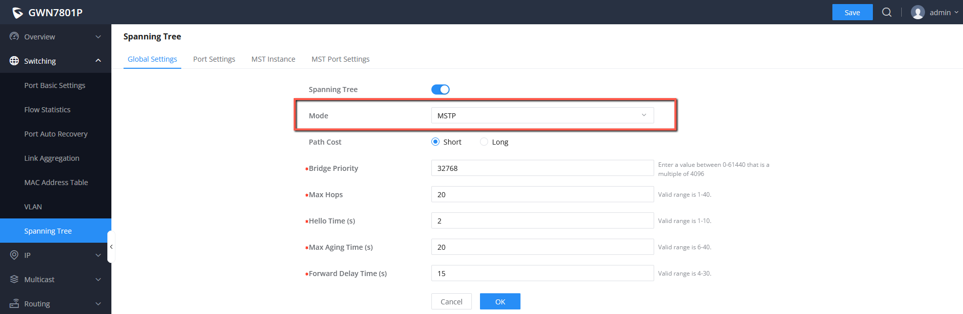
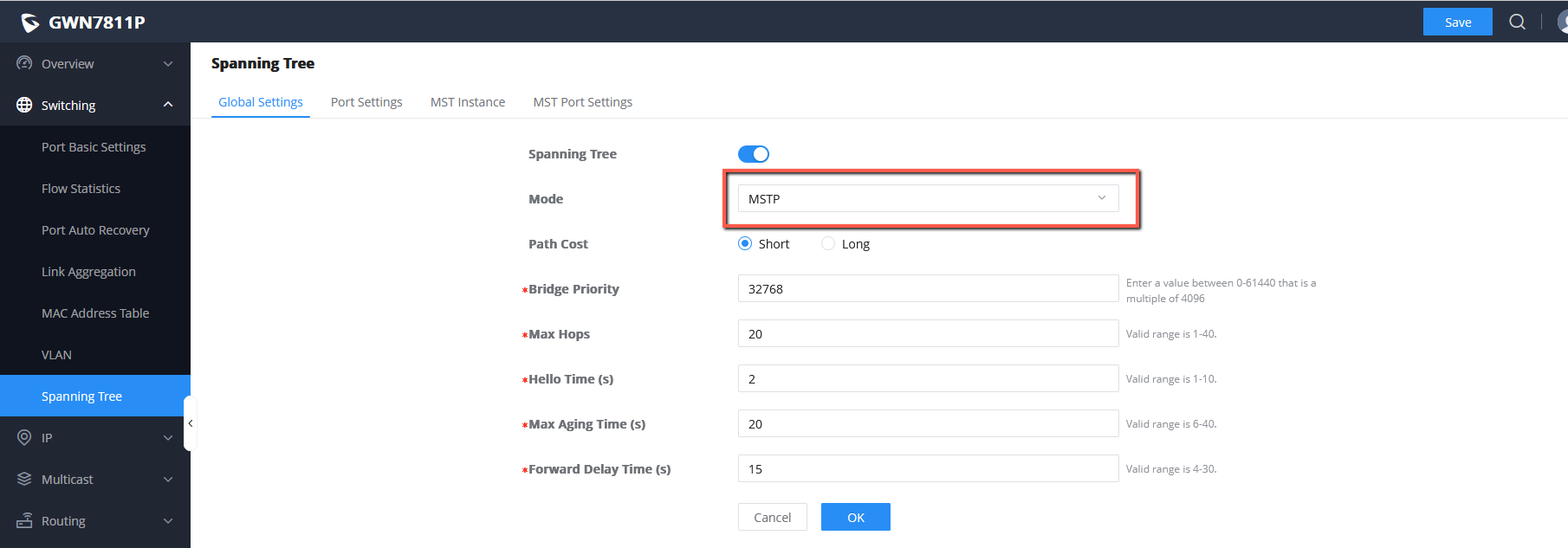
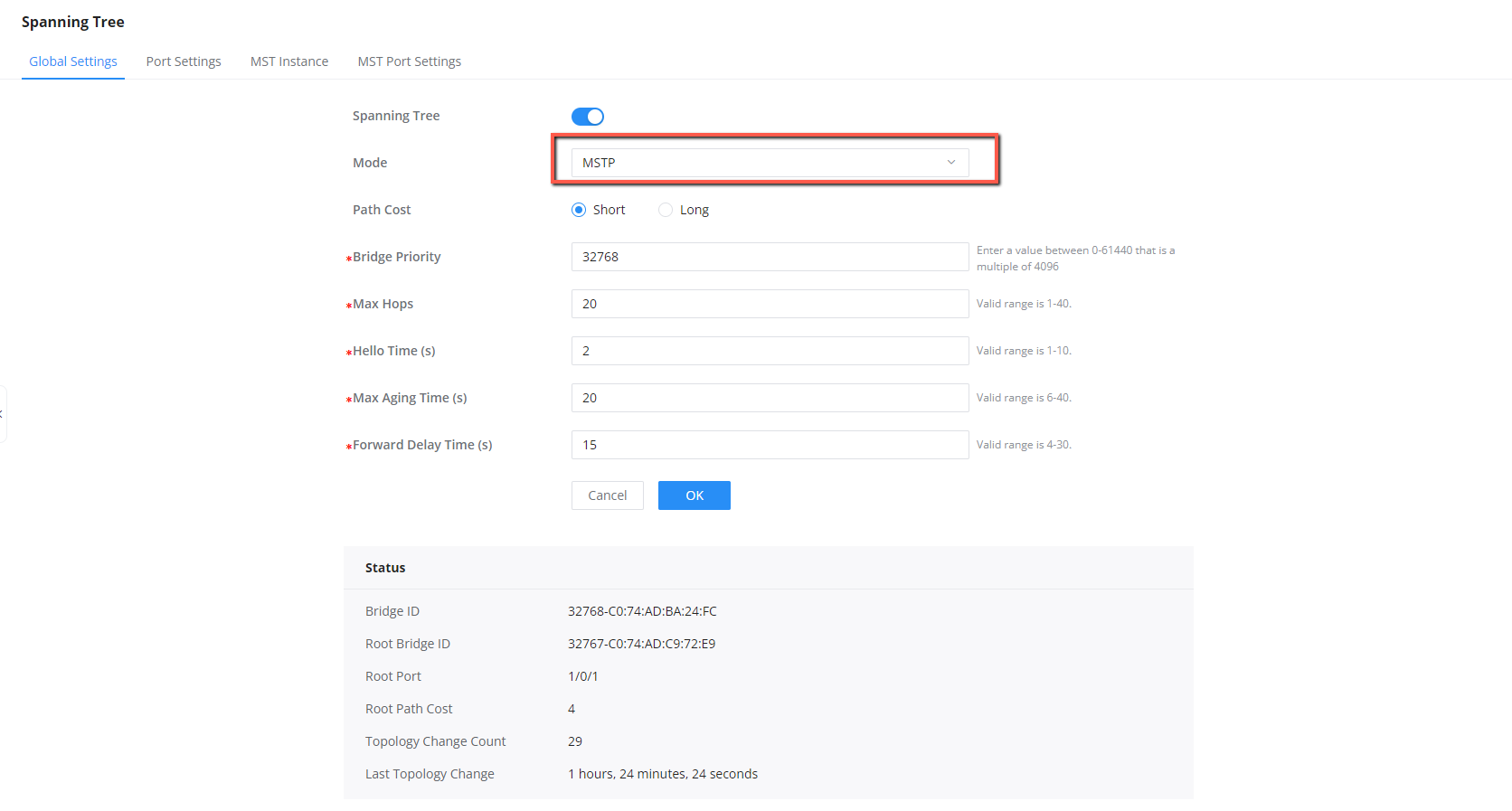
- Configure switches to work in MSTP mode and enable MSTP.
Switch A Configuration
- Configure MSTP region name, we will set it to “RG1”.
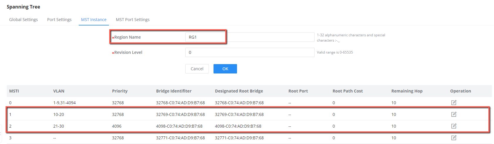
- Map VLANs to MSTI 1 and MSTI 2, we will map MSTI1 with VLAN 10-20 and MSTI2 with VLAN 21-30.
- Configure Switch A as root bridge in MSTI 1 by lowering its priority to 4096 and secondary root bridge on MSTI 2 by keeping its priority as default value 32768.
4. Disable STP on ports that are not part of the topology, keep only ports 1/0/1, 1/0/2 and 1/0/3.
5. Configure Switch A to work in MSTP mode, and enable MSTP.
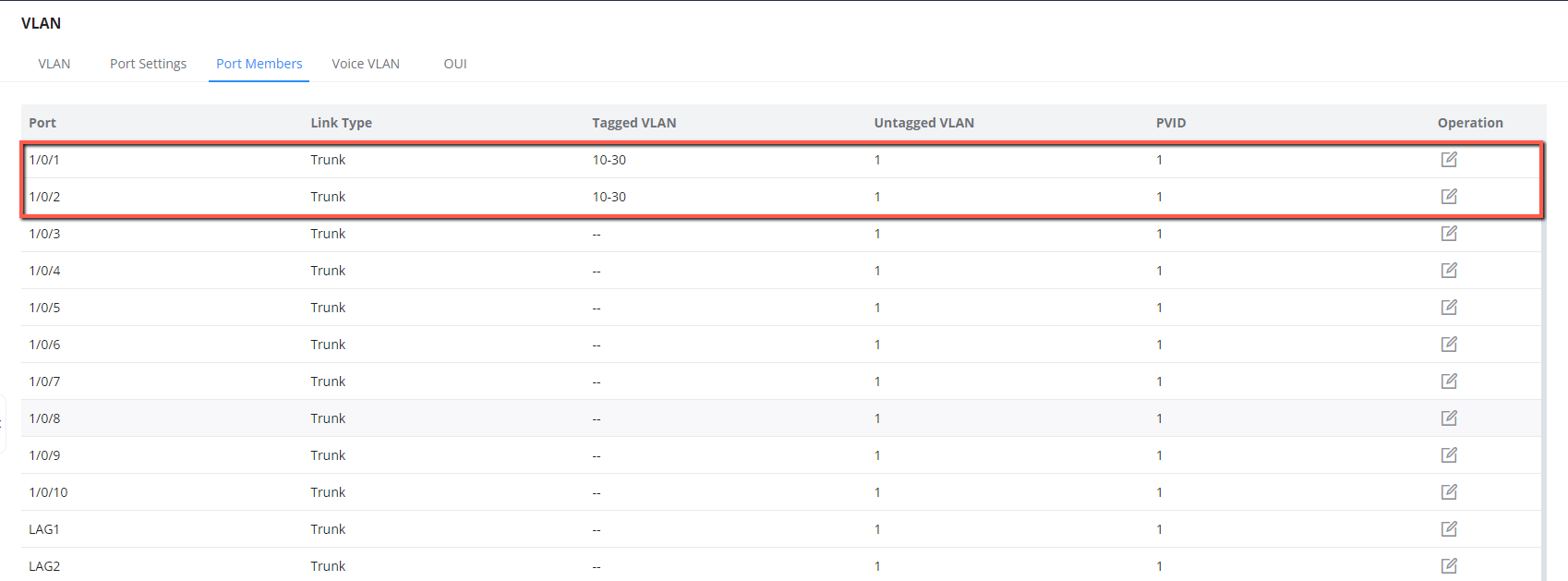
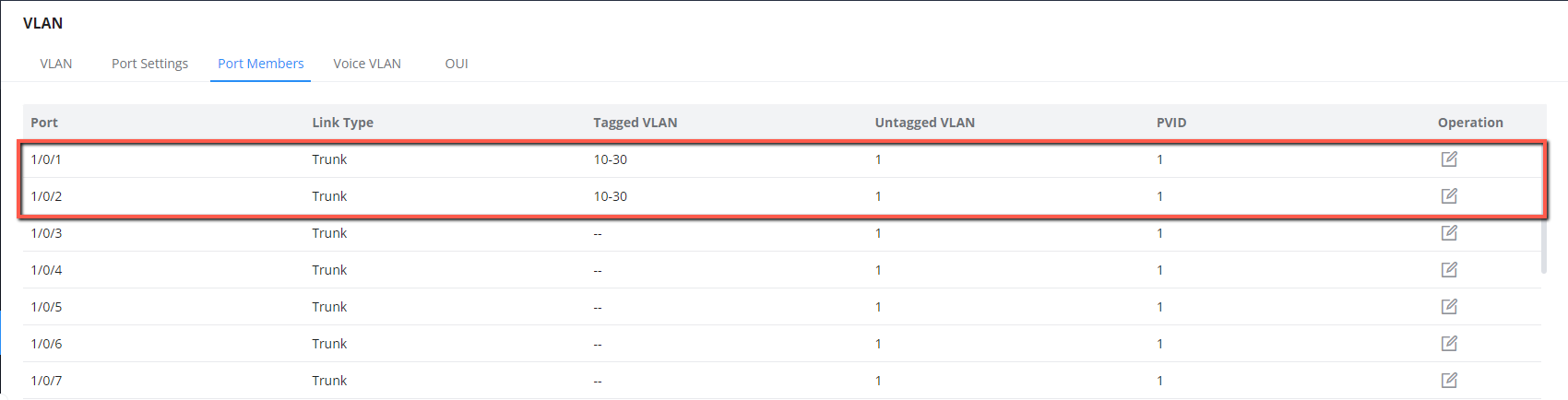
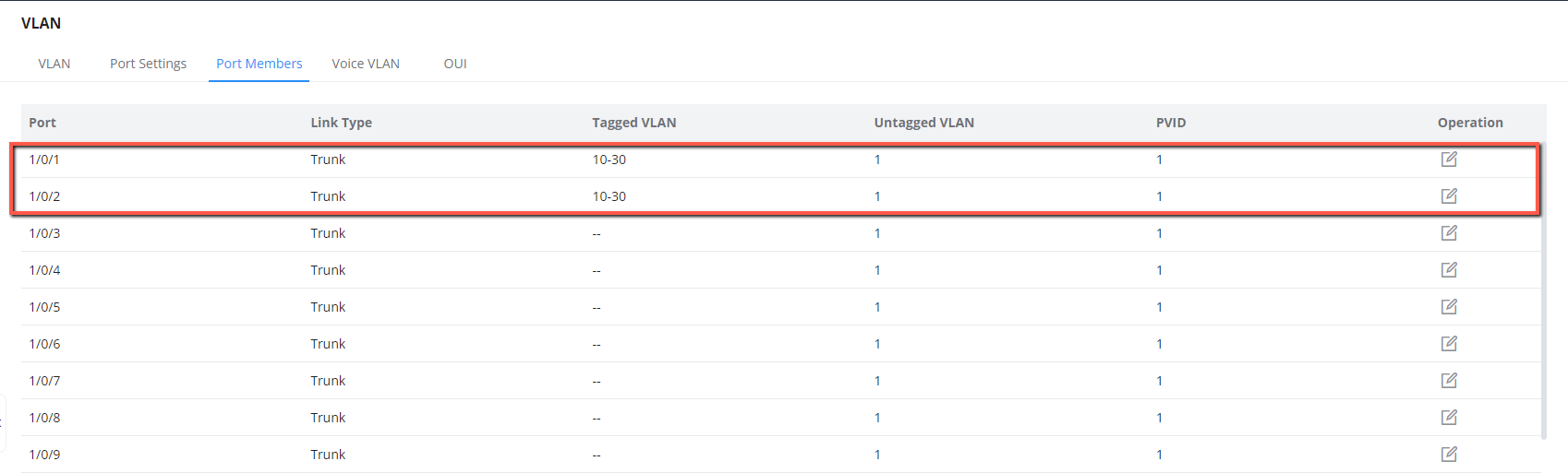
6. Batch create VLANs 10-30 and assign each VLAN individually with trunk ports 1/0/1 and 1/0/2.
Switch B Configuration
- Using the same steps, configure the region name and set it to “RG1”.
- Map VLANs to MSTI 1 and MSTI 2, we will map MSTI1 with VLAN 10-20 and MSTI2 with VLAN 21-30.
- Configure Switch A as root bridge in MSTI 2 by lowering its priority to 4096 and secondary root bridge on MSTI 1 by keeping its priority as default value 32768.
4. Disable STP on ports that are not part of the topology, keep STP enabled only on ports 1/0/1 and 1/0/2.
5. Configure Switch B to work in MSTP mode, and enable MSTP.
6. Batch create VLANs 10-30 and assign each VLAN individually with trunk ports 1/0/1 and 1/0/2.
Switch C Configuration
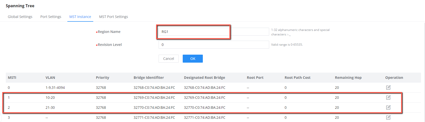
- Configure the region name and set it to “RG1”.
- Map VLANs to MSTI 1 and MSTI 2, we will map MSTI 1 with VLAN 10-20 and MSTI 2 with VLAN 21-30.
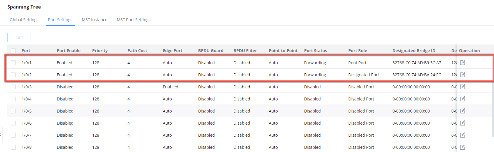
3. Disable STP on ports that are not part of the MSTP calculation, we will keep ports 1/0/1 and 1/0/2 enabled.
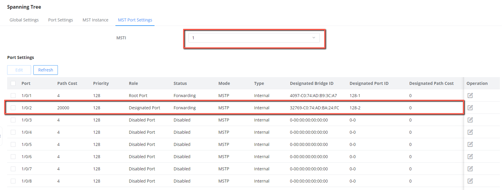
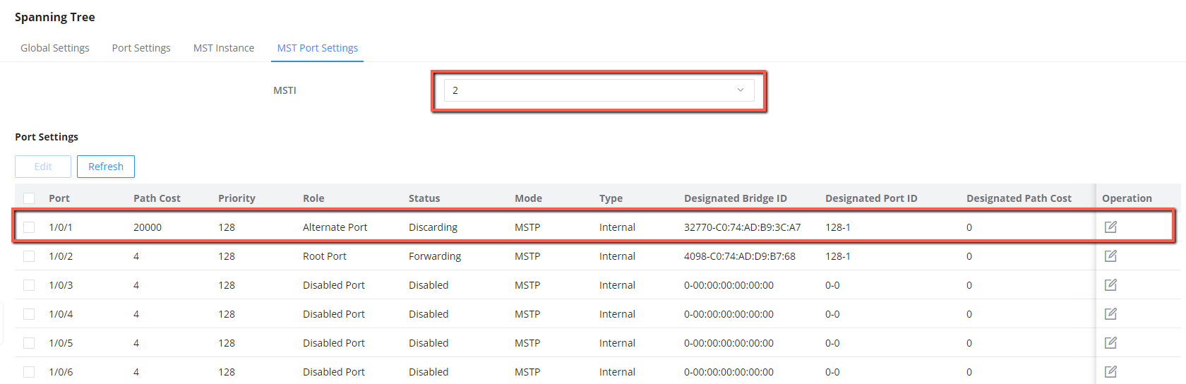
4. Set the path cost on 1/0/2 to 20000 in MSTI1.
5. Set the path cost on 1/0/1 to 20000 in MSTI2.
6. Configure Switch C to work in MSTP mode, and enable MSTP.
7. Batch create VLANs 10-30 and assign each VLAN individually with trunk ports 1/0/1 and 1/0/2.
Configuration Results
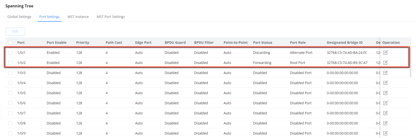
After the configuration is complete, Switch C will receive traffic from VLAN 10-30, but will differentiate between the traffic to allow and the traffic to block based on MSTI region configuration(MSTI1 with VLANs 10-20 and MSTI2 with VLANs 21-30), that has been defined by setting the path cost, the path with highest cost will be discarded.
Supported Devices
Device Name | Supported | Firmware Required |
GWN7801 | Yes | 1.0.1.20 or higher |
GWN7801P | Yes | 1.0.1.20 or higher |
GWN7802 | Yes | 1.0.1.20 or higher |
GWN7802P | Yes | 1.0.1.20 or higher |
GWN7803 | Yes | 1.0.1.20 or higher |
GWN7803P | Yes | 1.0.1.20 or higher |
GWN7811 | Yes | 1.0.1.8 or higher |
GWN7811P | Yes | 1.0.1.8 or higher |
GWN7812P | Yes | 1.0.1.8 or higher |
GWN7813 | Yes | 1.0.1.8 or higher |
GWN7813P | Yes | 1.0.1.8 or higher |
GWN7806 | Yes | 1.0.1.14 or higher |
GWN7806P | Yes | 1.0.3.3 or higher |
GWN7830 | Yes | 1.0.3.3 or higher |
GWN7831 | Yes | 1.0.3.3 or higher |
GWN7832 | Yes | 1.0.3.3 or higher |
List of supported devices