Overview
Spanning Tree Protocol (STP) is a network protocol designed to prevent loops in Layer 2 and Layer 3 switched networks. When multiple paths exist between switches, loops can cause broadcast storms, network congestion, and other problems. STP resolves this issue by creating a loop-free topology.
This guide will cover the process of configuring the Spanning Tree Protocol on GWN78xx network switches by manually electing a switch as a Root Bridge.
Pre-Configuration Considerations
Understand the Network Topology and Potential Loop Scenarios
Before configuring Spanning Tree Protocol (STP) on GWN78xx Layer 2 and Layer 3 switches, it is crucial to have a thorough understanding of the network topology, identify the switches, their interconnections, and the potential paths for data to flow between them. This understanding helps identify any potential loop scenarios, where redundant links may exist, increasing the risk of network loops and related issues.
By analyzing the network topology, you can identify areas where loops may occur due to multiple paths between switches. This knowledge will aid in configuring STP to create a loop-free topology and ensure efficient data transmission.
Determine the Root Bridge and its Priority
STP elects automatically a root bridge as the central point of the network. The Root Bridge serves as the reference point for calculating the shortest path to other switches.
The network administrator can also set a switch to act as Root Bridge manually by setting its Bridge Priority.
By default, switches have a priority value of 32768, and the switch with the lowest priority becomes the root bridge. The lowest supported value is 4096.
Identify Port roles and states in STP
STP assigns roles and states to each switch port in the network. Understanding these roles and states is crucial for configuring STP effectively.
The main port roles in STP are:
- Root Port: The path to the Root Bridge with the lowest cost on a non-root bridge.
- Designated Port: The primary forwarding port for a network segment on a bridge.
- Blocking Port: Prevents loops by blocking data forwarding, monitors the network.
The port states in STP include:
- Blocking State: The port is in a blocking state, not forwarding data to prevent loops while listening to network traffic.
- Listening State: A transitional state where the port prepares to transition to the learning state.
- Learning State: The port is in the process of learning MAC addresses and updating its MAC address table but still not forwarding data.
- Forwarding State: The port is actively forwarding data frames within the STP-defined topology.
- Disabled State: The port has been manually administratively disabled and does not participate in STP.
Identifying the port roles and states in the network helps in understating STP to ensure optimal traffic flow and loop prevention.
Configuration Example
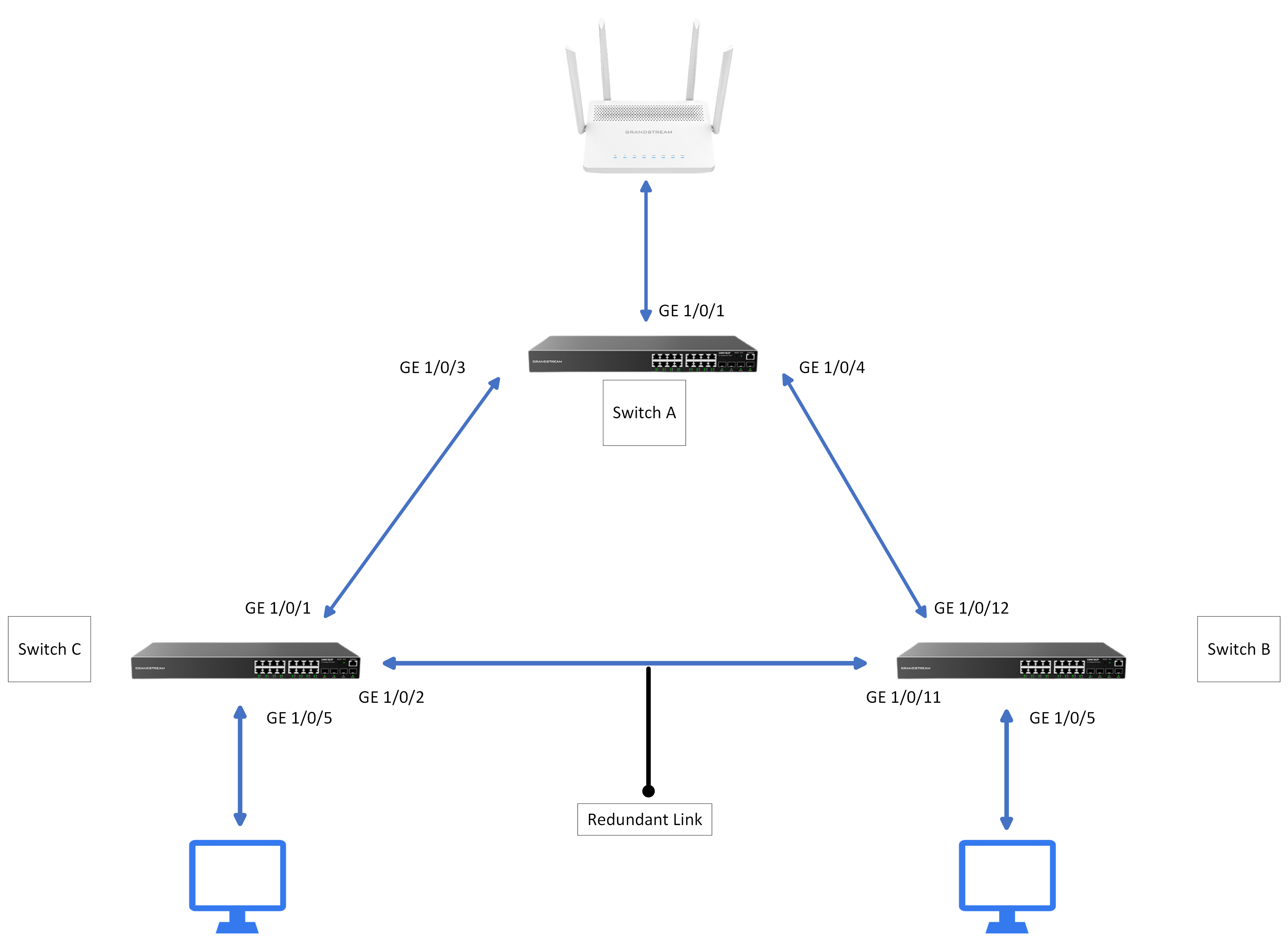
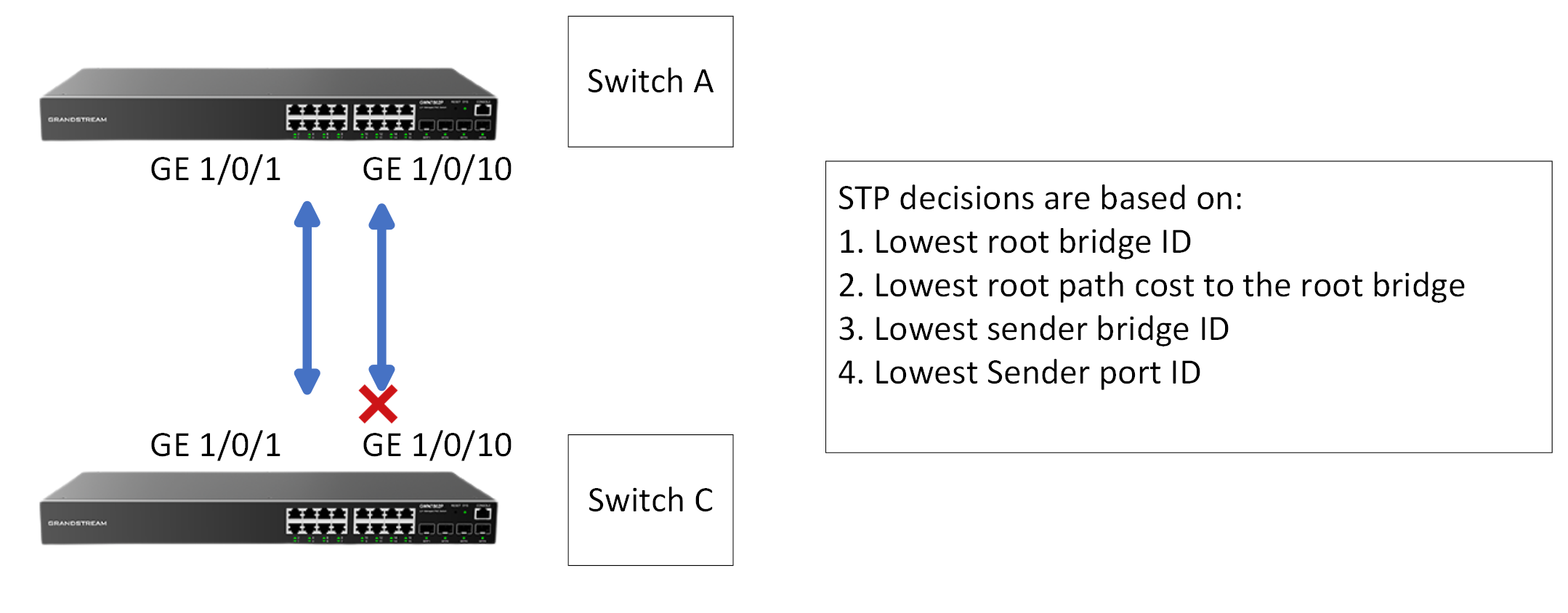
In this section of the guide, we will configure the Spanning Tree Protocol on three GWN78XX(P) network switches and add a redundant link, as shown in the illustration below.
STP Configuration
After accessing the Web UI of the three switches, choose the one that you want to configure as the root bridge and follow the below steps to execute that :
- Go to Switching > Spanning Tree > Global Settings, enable Spanning Tree, and set the Spanning Tree mode to STP as shown below.
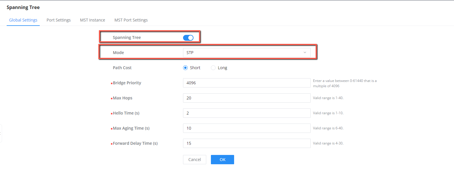
2. Select the Path Cost to be either Short or Long. We will leave it Short as Default.
It’s important to understand that the path cost serves as the measurement used by STP to determine the shortest and quickest path to the selected root bridge, the path cost directly impacts this calculation.
STP Path Cost | ||
Link Bandwidth | Short | Long |
10 Mbps | 100 | 2000000 |
100 Mbps | 19 | 200000 |
1 Gbps | 4 | 20000 |
10 Gbps | 2 | 2000 |
100 Gbps | 1 | 200 |
1 Tbps | 1 | 20 |
10Tbps | 1 | 2 |
STP Path cost
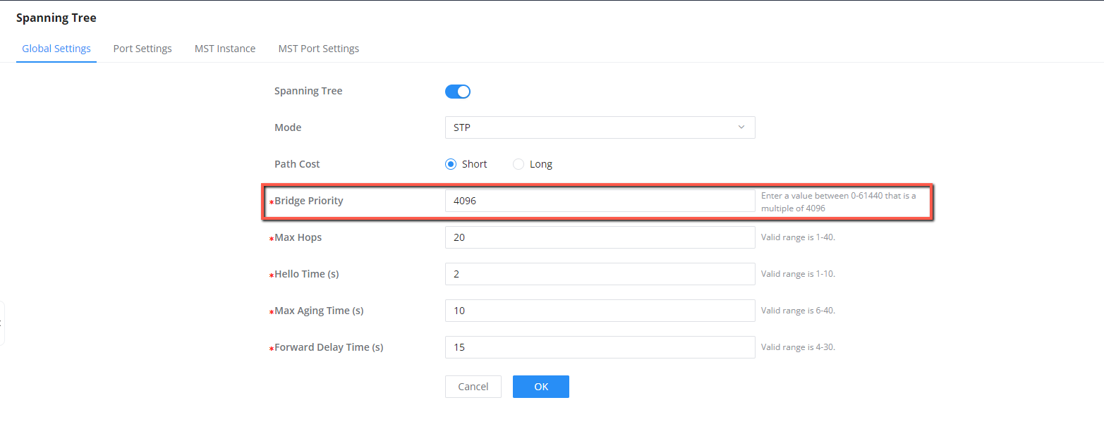
3. Select the Bridge Priority.
Please note that the switch that will be elected as the Root bridge needs to have the lowest Bridge Priority. In our case, we will set the current “Switch A” as the root bridge and we will assign it the lowest Priority (4096). The priority can only be a multiple of 4096.
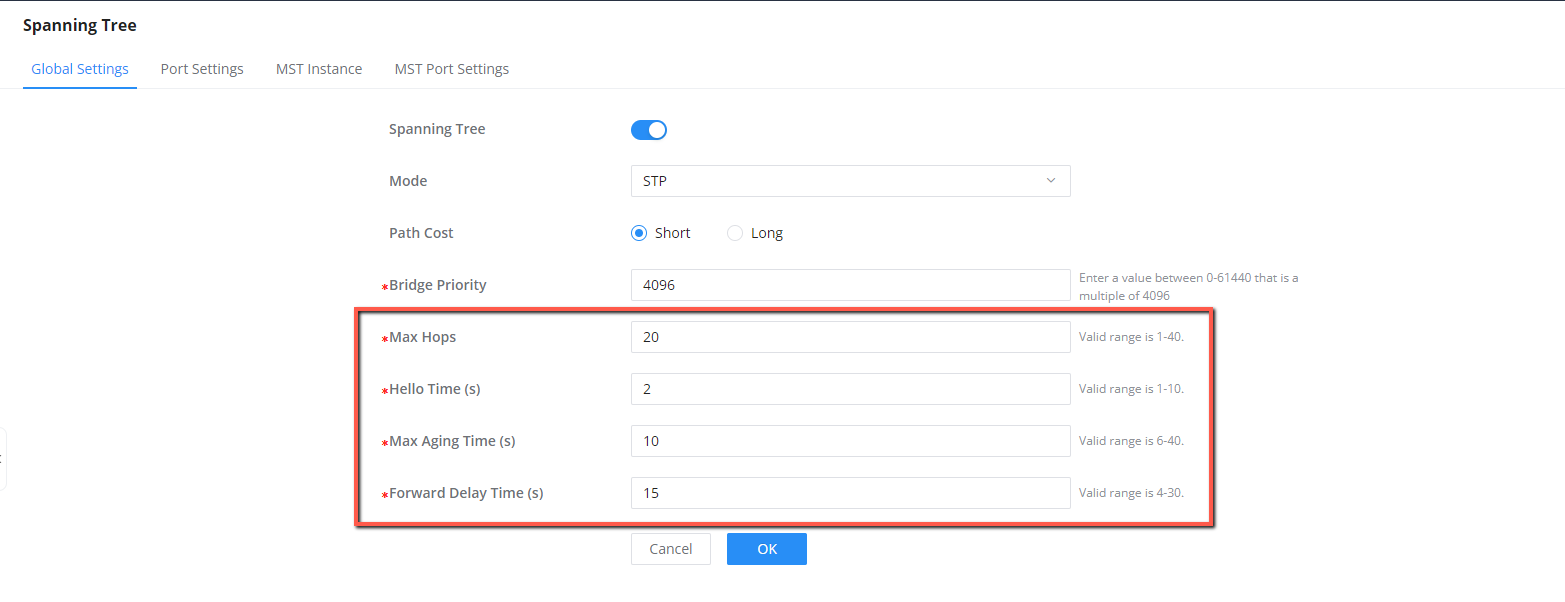
4. Select the Max Hops.
This is basically the number of switches the BPDU traverses before it’s discarded, we set the value to 20 hops.
5. Select the “Hello Time” in seconds.
This is the sending interval between the BPDU messages. We set the value to 2 seconds.
6. Select the Max Aging Time in seconds.
This is used to decide whether stored BPDU is expired or not, we set the value to 10 seconds, which means if it exceeds 10 seconds, the BPDU messages will be expired, we will set the same value (10s) on the two other switches configured for STP.
7. Select the Forward Delay Time in seconds.
This is the period that the port spends on the listening and learning states, we will set it to 15 seconds.
After the configuration is completed on the switch chosen as the root bridge, we will repeat the same configuration on the two other switches, with the difference being the bridge priority, both switches will have a priority higher than the root bridge (4096), this will give us the results shown below :
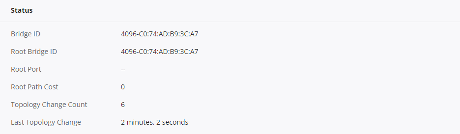
- Switch A (Root Bridge)
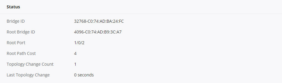
- Switch B:
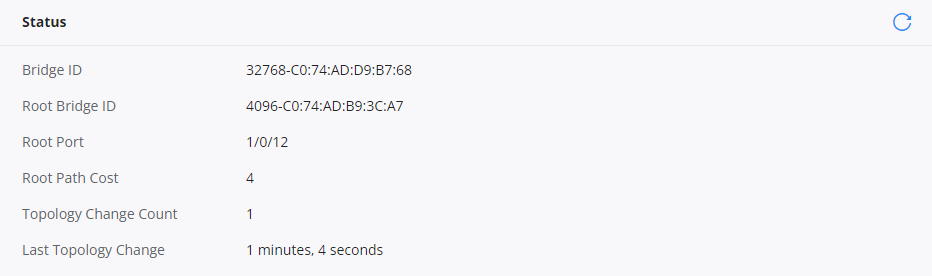
- Switch C:
Configuration Results
When completing the configuration, the outcome will be as follows:
The network loop will be prevented by blocking the redundant link on port 1/0/11 of switch B.
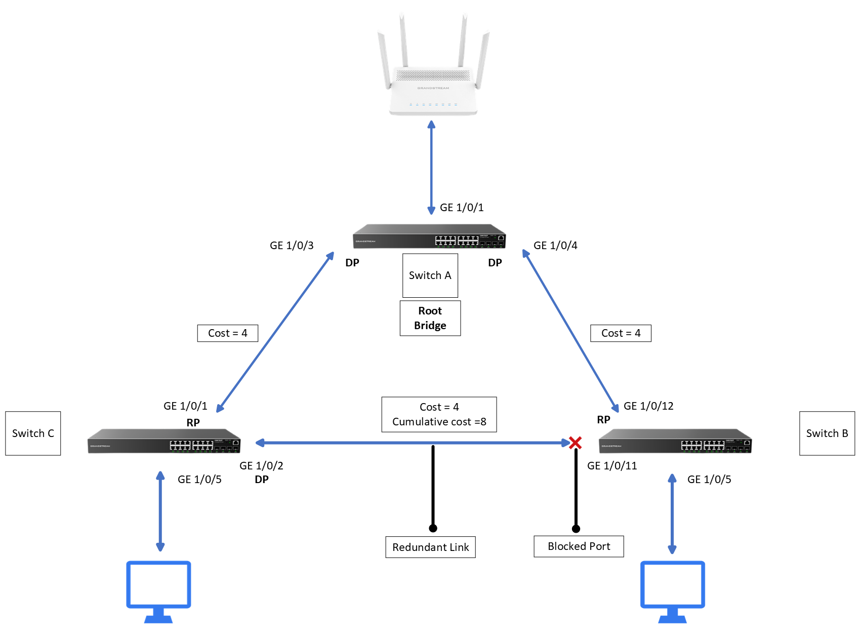
Up to here, the network is loop free, thanks to the Spanning Tree Protocol.
The network administrator can still optimize the STP performance. Please refer to the STP Optimization section below.
STP Optimization
This section provides instructions to optimize the STP network for better performance in your network.
The optimization includes:
- Disabling non-STP Ports
- Setting Port Priority
- Enabling Edge Port and BPDU Guard
- Enabling BPDU Filter
Disabling non-STP-related Ports
Once the STP protocol is enabled on the network topology, you can view the status of All available ports in a switch, including some important information such as port enable, the port status, the port role, the designated port ID, and more…
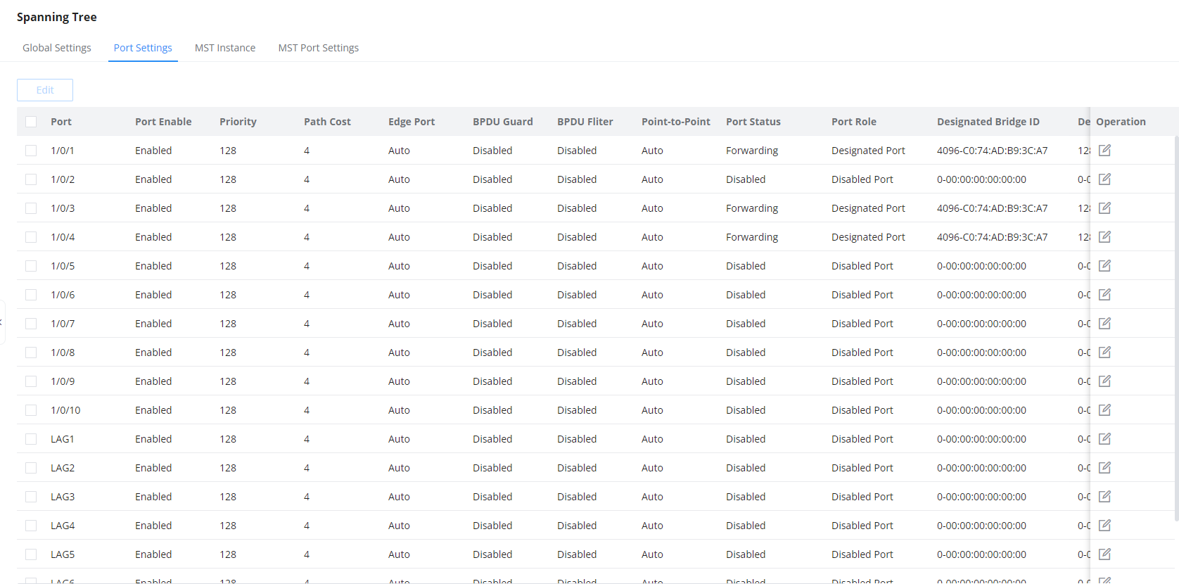
When you enable STP globally under global settings, it gets automatically enabled on all ports of the switch, you can disable it manually on all ports.
To achieve this, ensure you identify the ports participating in the STP calculation – they are the ones with the Port status marked as forwarding, indicating they are in the forwarding state of the STP topology. For those marked as disabled ports, it is safe to disable STP on them.
On the STP port settings, you have the option to specify which ports will not have STP enabled and which ones will have BPDU guard activated in the event of a link failure.
All of this can be configured as shown below :
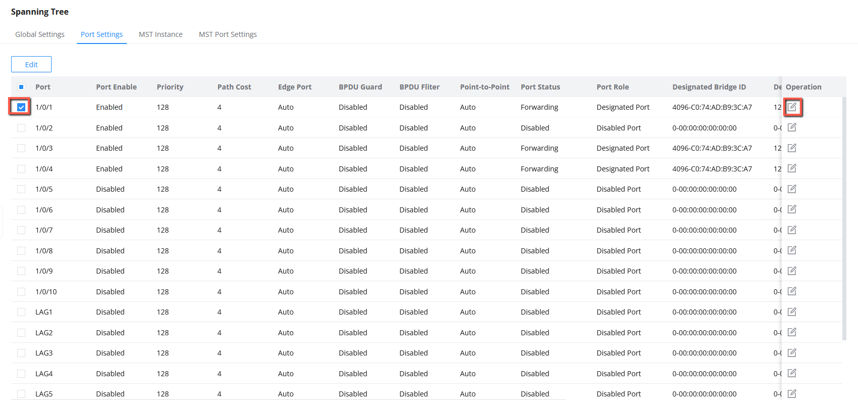
- Under Switching > Spanning Tree > Port Settings, you can choose the desired port(s) by selecting it and clicking the icon
 under operation to edit it.
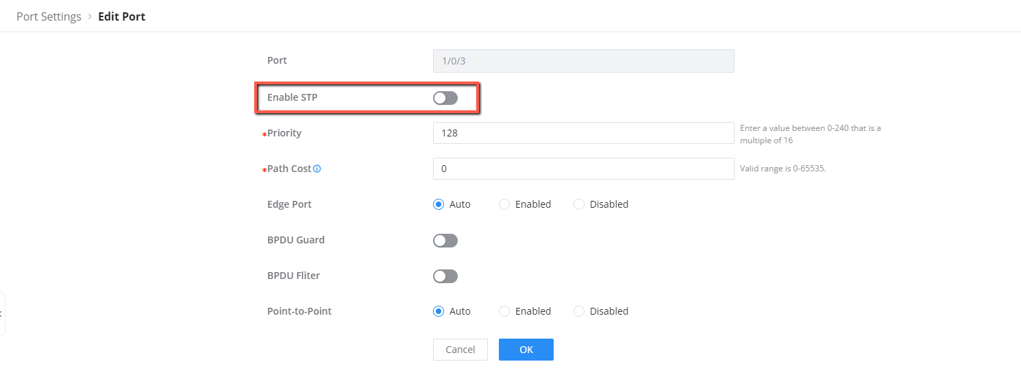
2. Toggle the “Enable STP” Option.
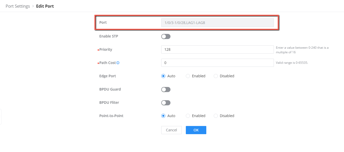
3. You can do this also for all the ports not participating in the STP topolgy by selecting them all then clicking the![]() button to disable STP on all selected ports:
button to disable STP on all selected ports:
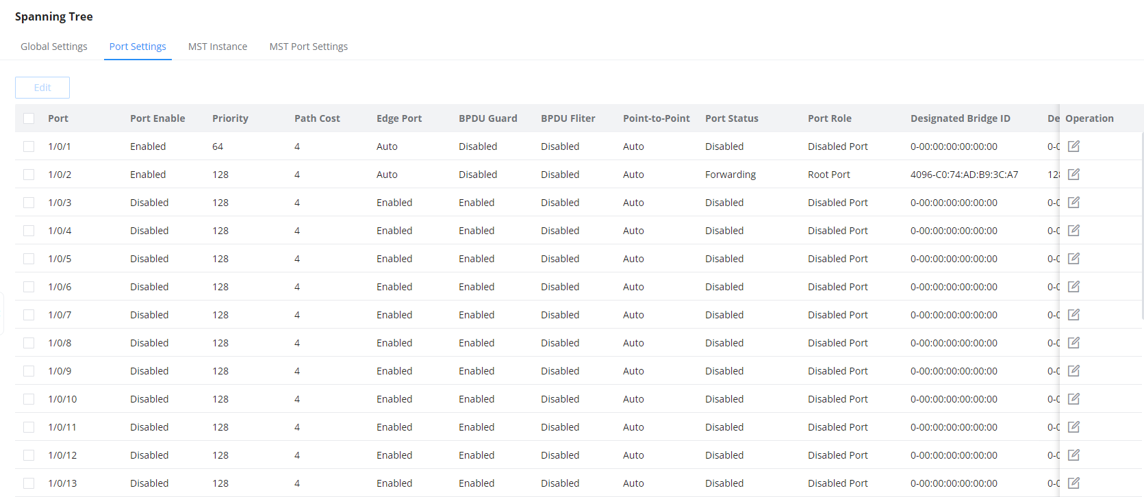
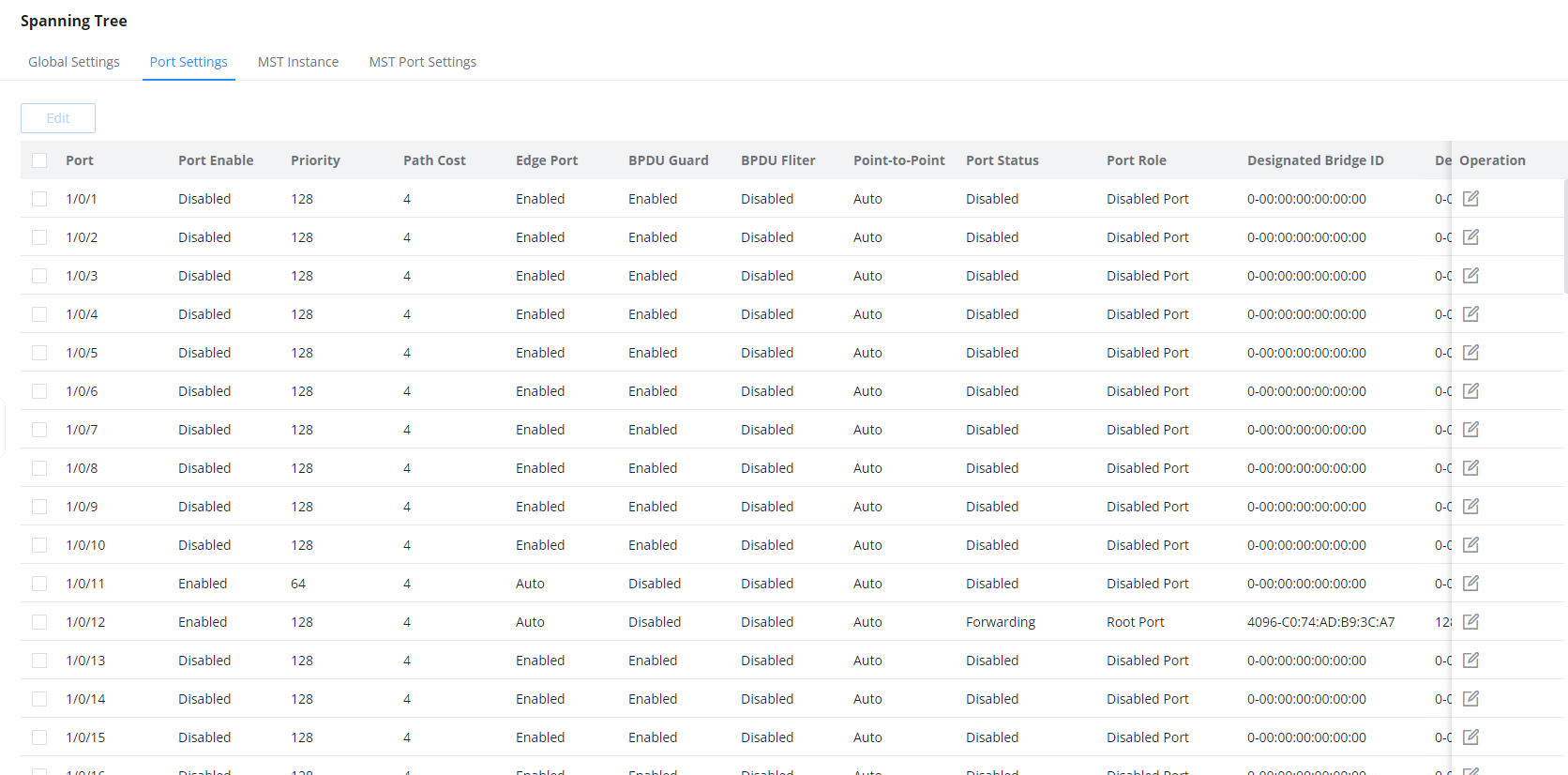
4. We will disable STP on all the ports of switch B except 1/0/1 and 1/0/2 and all the ports of switch C except 1/0/11 and 1/0/12 , these four ports will be part of the spanning tree protocol, the results can be monitored below :
- Switch B
- Switch C
Setting Port Priorities
Next step is to modify port priorities: Set initially at 128 (default), the valid range is 0-240, in multiples of 16. this step is useful for designating a forwarding state when dealing with redundant links between switches, this means in case we want to implement a link aggregation set up between two connected switches and to avoid loops, we can set one link to be advantageous than the other.
Lower priority value takes precedence in determining the STP state when sharing the same bridge ID, root path cost, and sender bridge ID.
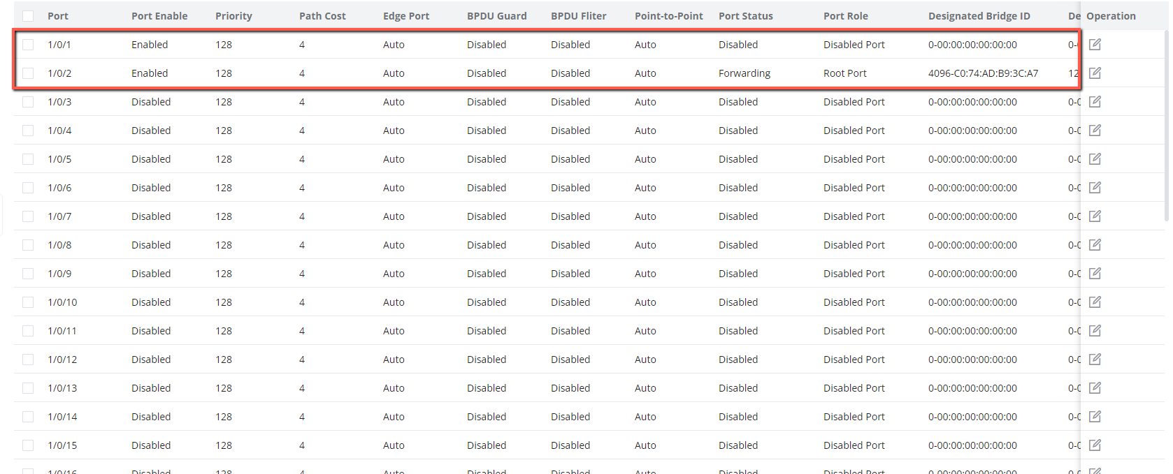
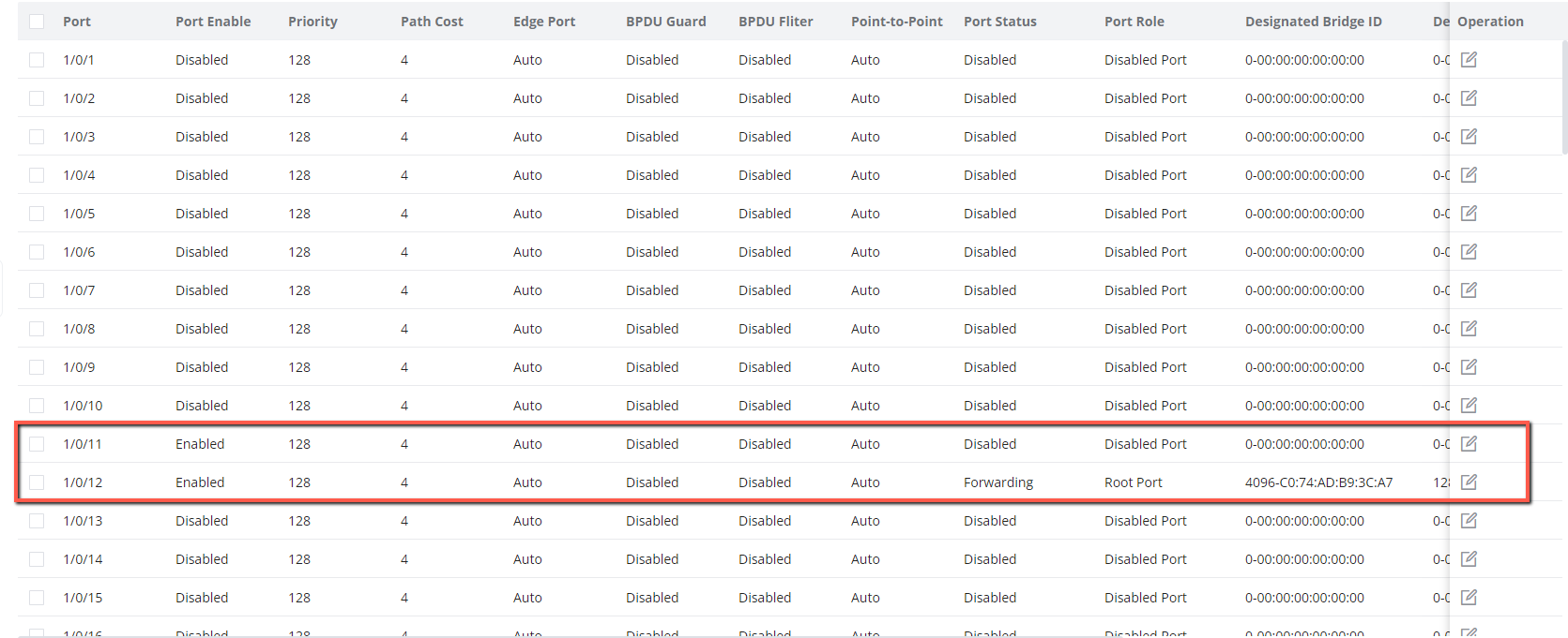
We will set one of the ports on each switch to 64 value and the results will be:
- Switch A

- Switch C

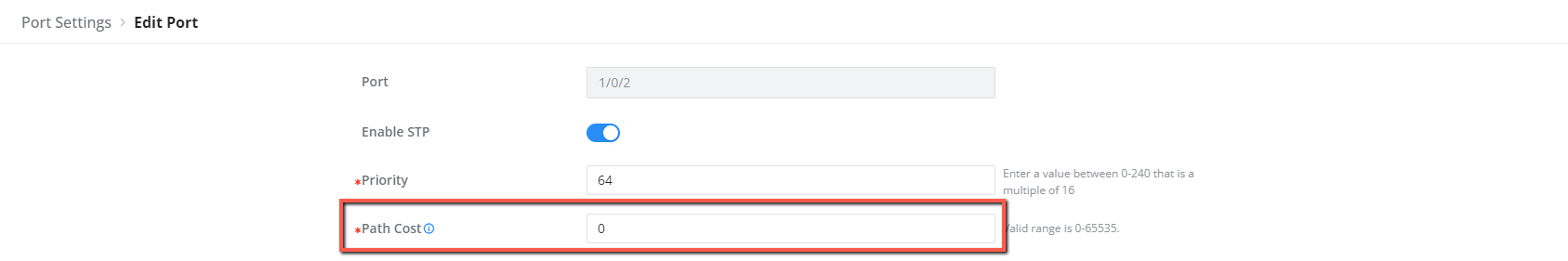
Set the Path cost to 0 for all the ports in the STP protocol, 0 indicates to automatically determine the path cost based on port speed and the path cost method (long or short)
Enabling Edge Port and BPDU Guard
Enable the Edge Port and BPDU Guard on all ports that are not included in the STP protocol. this will be ports 1/0/3-1/0/28 in Switch B, and ports 1/0/1-1/0/10,1/0/13-1/0/54 in Switch C, this feature should be enabled only on ports where bridging loops are not expected, such as endpoints: Computers and Servers.
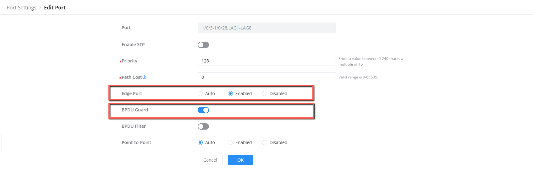
- Switch B
- Switch C
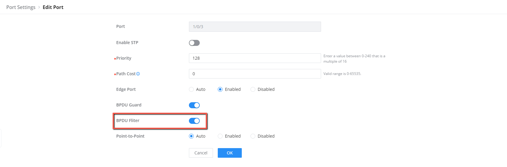
Enabling BPDU Filter
Finally, we can activate the BPDU Filter on all ports of the switches that will not be participating in STP topology, these are ports 1/0/3-1/0/28 in Switch B, and ports 1/0/1-1/0/10,1/0/13-1/0/54 in Switch C, on these ports, BPDU messages will be restricted.
Supported Devices
Device Name | Supported | Firmware Required |
GWN7801 | Yes | 1.0.1.20 or higher |
GWN7801P | Yes | 1.0.1.20 or higher |
GWN7802 | Yes | 1.0.1.20 or higher |
GWN7802P | Yes | 1.0.1.20 or higher |
GWN7803 | Yes | 1.0.1.20 or higher |
GWN7803P | Yes | 1.0.1.20 or higher |
GWN7811 | Yes | 1.0.1.8 or higher |
GWN7811P | Yes | 1.0.1.8 or higher |
GWN7812P | Yes | 1.0.1.8 or higher |
GWN7813 | Yes | 1.0.1.8 or higher |
GWN7813P | Yes | 1.0.1.8 or higher |
GWN7806 | Yes | 1.0.1.14 or higher |
GWN7806P | Yes | 1.0.3.3 or higher |
GWN7830 | Yes | 1.0.3.3 or higher |
GWN7831 | Yes | 1.0.3.3 or higher |
GWN7832 | Yes | 1.0.3.3 or higher |
List of supported devices