Overview
RSTP (Rapid Spanning Tree Protocol), defined by the IEEE 802.1w standard, is an enhancement over STP. It offers faster convergence times and provides a faster transition to a new network topology when there is a change in the network, such as a link failure or addition.
RSTP achieves this by introducing new port states (discarding and learning), which reduce the time taken for a port to transition from blocking to forwarding. RSTP is backward compatible with STP, allowing it to interoperate with older STP implementations.
RSTP vs STP
The following table introduces the common differences between the two Protocols STP and RSTP
STP | RSTP |
In STP, only the root bridge transmits BPDU (Bridge Protocol Data Unit), which is then relayed by the other bridges in the network. | In RSTP, all bridges have the ability to forward BPDUs (Bridge Protocol Data Units). |
STP has three port roles (i.e., Root Port, Designated Port, Blocking Port).
| RSTP has four-port roles (i.e., Root Port, Designated Port, Alternate Port, Backup Port).
|
STP has five port states (i.e., Forwarding, Learning, Listening, Blocking, Disabled).
| RSTP has three port states (i.e., Forwarding, Learning, Discarding).
|
STP provides slower network convergence in response. (30-50 seconds) | RSTP provides significantly faster network convergence. (1-2 seconds) |
Configuration Example
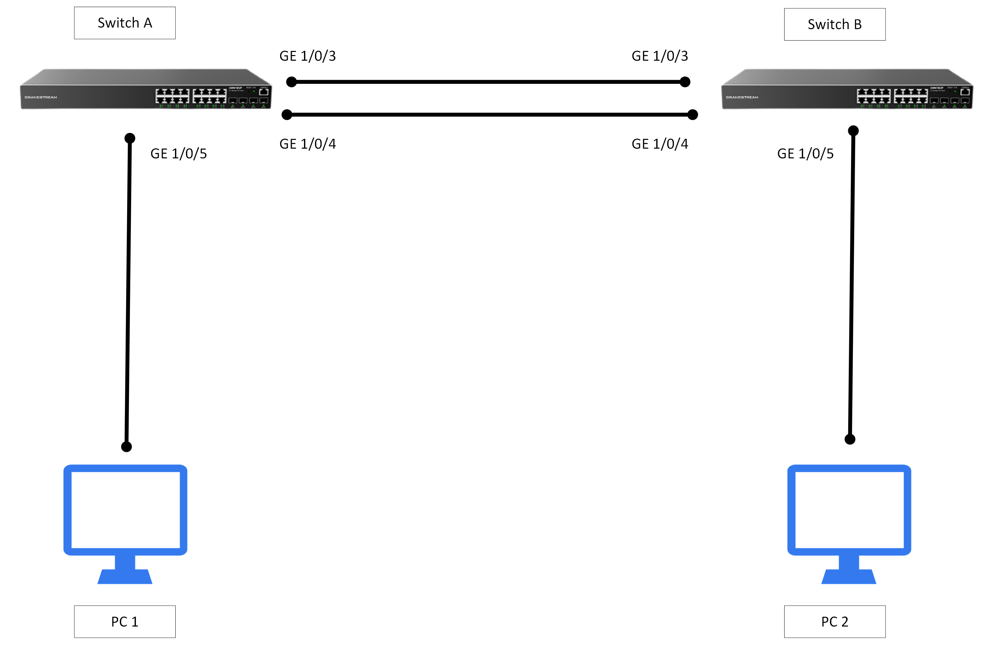
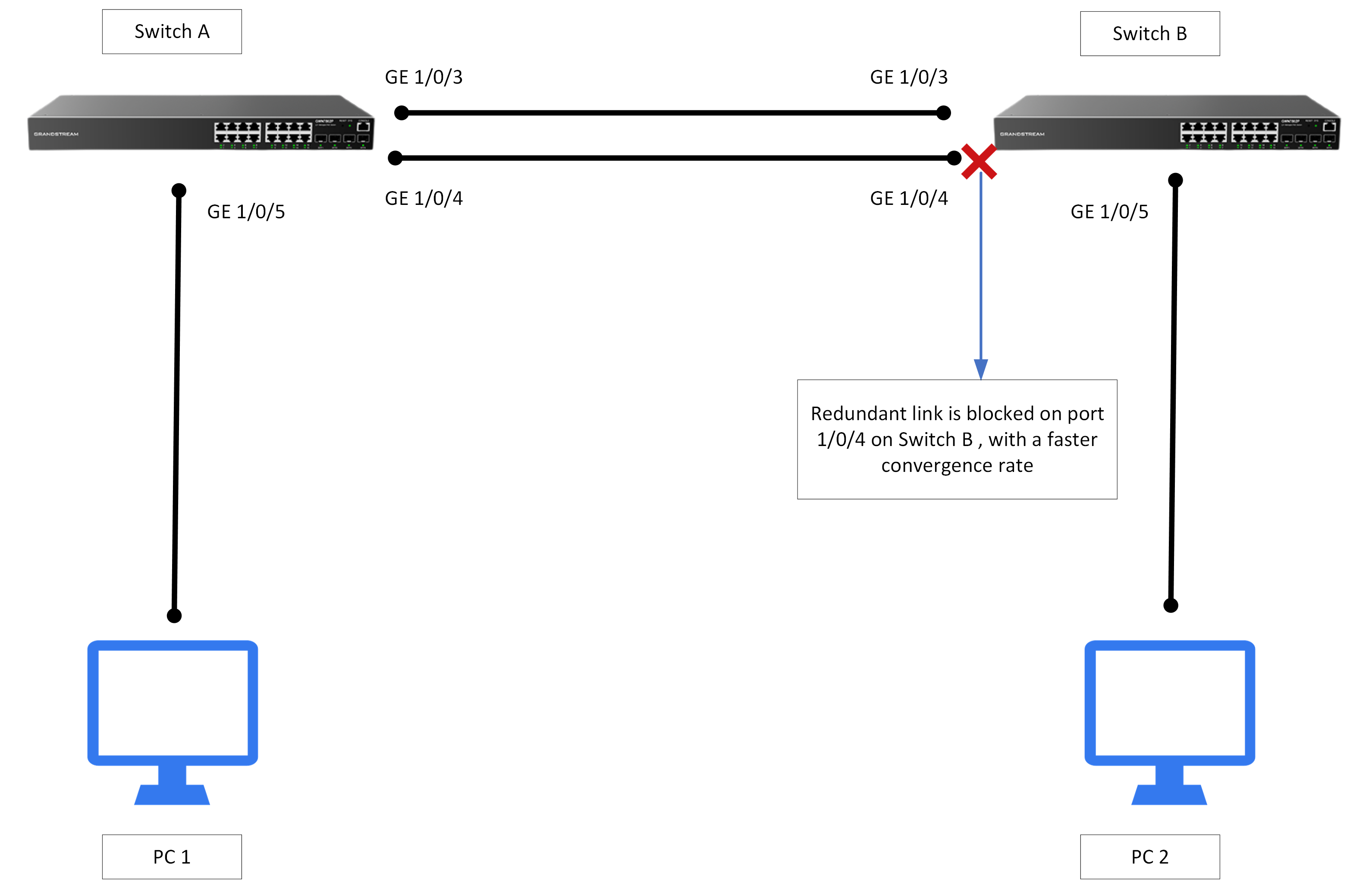
In this section of the guide, we will configure the Rapid Spanning Tree protocol on two connected GWN78XX(P) Switches,
RSTP configuration
In RSTP, an edge port is a port that is known to be connected to an end device and is not expected to receive BPDUs. Edge ports in RSTP are similar to non-designated ports in STP and immediately transition to the forwarding state, avoiding the blocking and listening states, keep this in mind while we go through the below configuration.
The configuration on both switches is as follows:
- Enable RSTP on both switches.
- Set the Convergence parameters.
- Set the bridge priority on both switches.
- Modify port priorities
- Configuration of an edge port on each switch where the end device will be connected.
- Configuration of RSTP BPDU Guard on the port connected to the end device.
Switch A&B Configuration
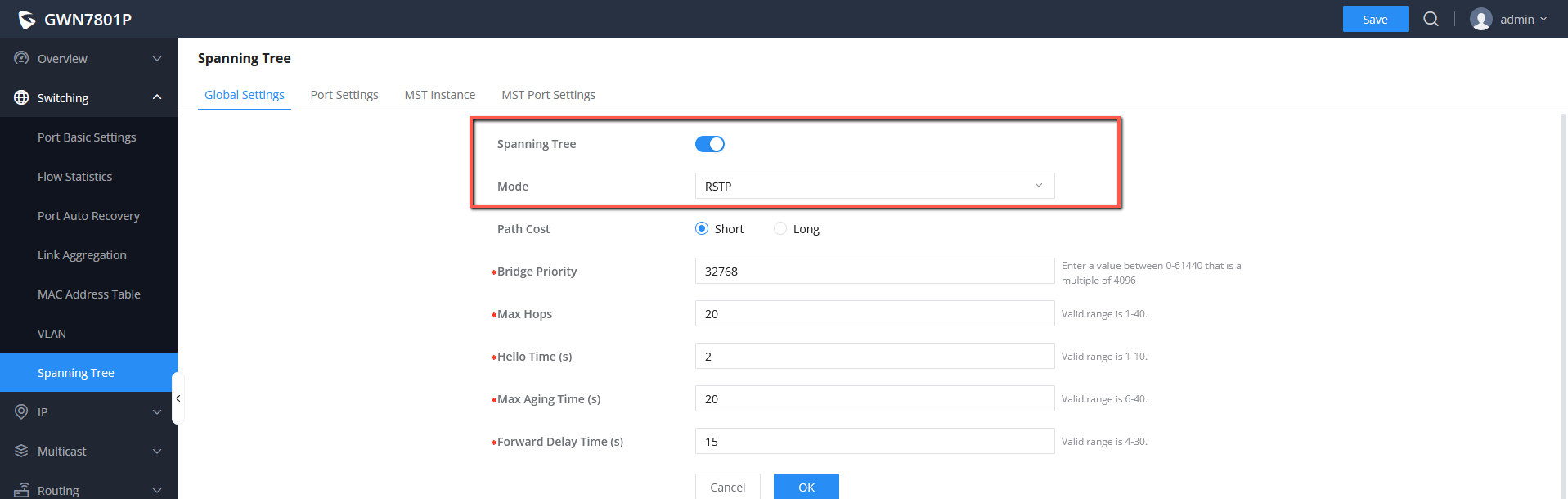
- Enable STP and set STP mode to RSTP on both Switch A and Switch B, leave all the other parameters as configured by Default.
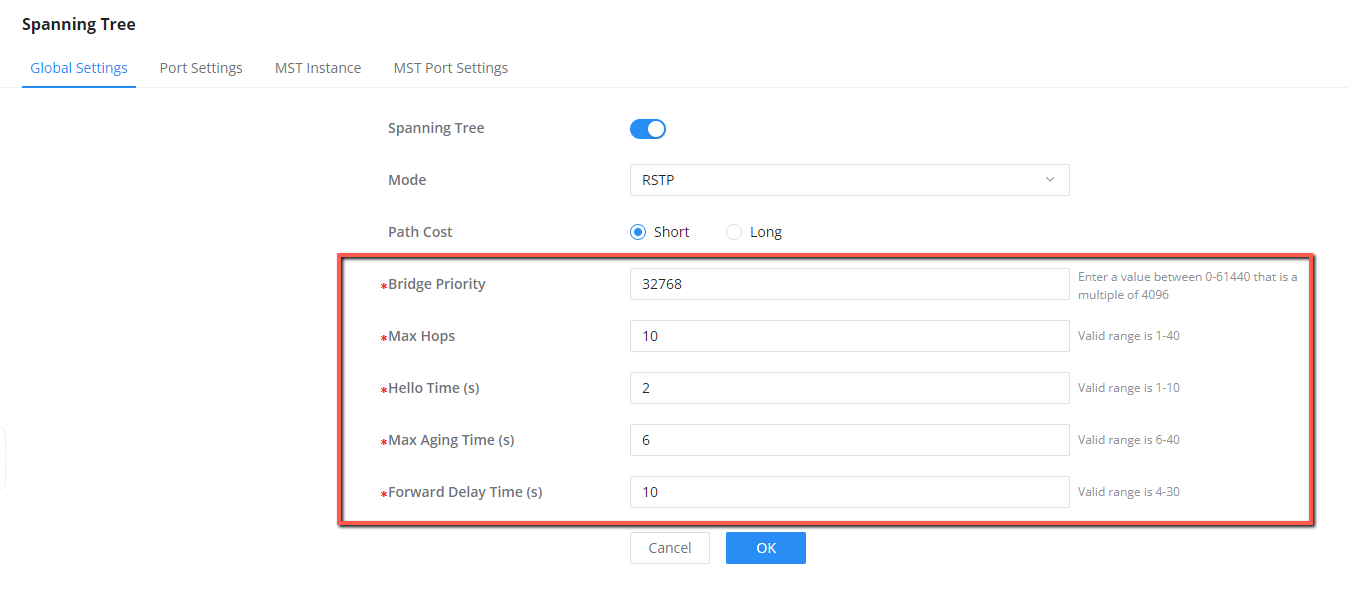
2. Set the Following Parameters as follows:
- Max Hops => 20: This is basically the number of switches the BPDU traverses before it’s discarded
- Hello Time (s) => 2: This is the sending interval between the BPDU messages.
- Max Aging Time (s) => 6: This is used to decide whether stored BPDU is expired or not, we set the value to 10 seconds, which means if it exceeds 10 seconds, the BPDU messages will be expired,
- Forward Delay Time (s) =>10: This is the period that the port spends on only learning states.
3. Set the Bridge priority on both switches as follows:
- Switch A ( Root ) : 4096
- Switch B: 32768
4. Next step is to modify port priorities: Set initially at 128 (default), the valid range is 0-240, in multiples of 16. this step is useful for designating a forwarding state when dealing with redundant links between switches. Lower priority value takes precedence in determining the STP state when sharing the same bridge ID, root path cost, and sender bridge ID.
- Switch A

- Switch B

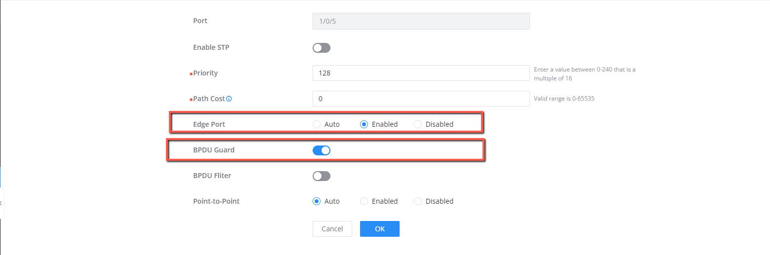
5. Configure Port 1/0/5 on both switches as an edge port to prevent its involvement in RSTP calculations, as it will be connected to an endpoint.
6. Since edge ports are directly connected to user terminal and will not receive BPDUs, we set BPDU Guard on Port 1/0/5, to avoid any sent attacks that might trigger new spanning tree calculations.
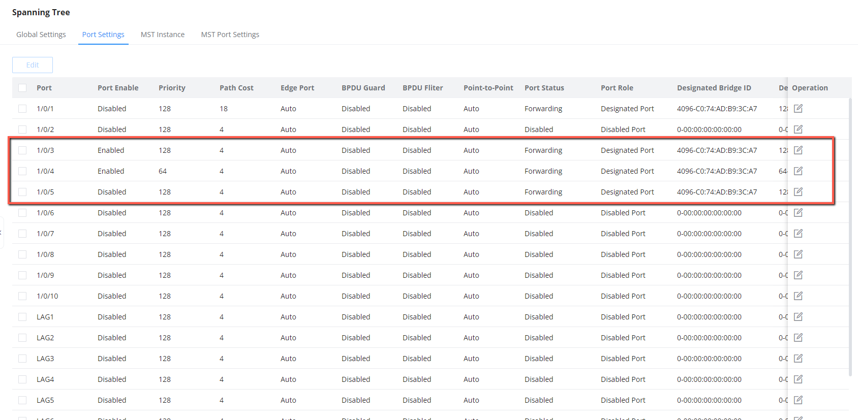
Port status
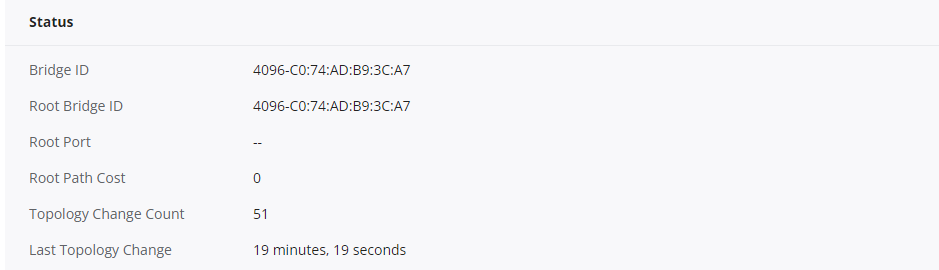
After Adding a redundant link on port 1/0/4 on switch B , the Port status are marked as shown below:
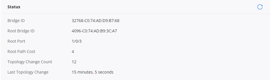
- Switch A: ( Root Bridge )
- Switch B
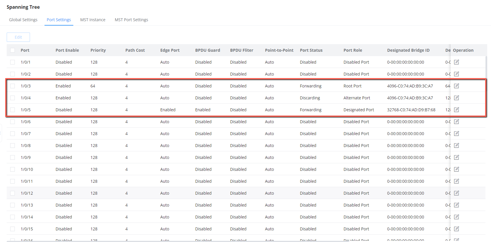
Based on the provided screenshot above, it’s evident that on the redundant link (port 1/0/4), the port is designated as an “Alternate port.” This particular port serves as a backup, ready to switch to the Forwarding state when the current Root or Designated Port (1/0/3) experience a failure. Additionally, the Port status is marked as “discarding,” signifying its current state of discarding incoming frames while actively monitoring for Bridge Protocol Data Units (BPDUs).
Results
The network configuration using RSTP, edge port configuration, and BPDU Guard on Port 1/0/5 of each switch results in a faster and more secure network. RSTP reduces convergence time (from 30 seconds to only 3 seconds), the edge port designation optimizes performance for directly connected devices, and BPDU Guard enhances security by preventing unauthorized BPDUs. This overall configuration ensures a more efficient and stable network operation.
This represents a straightforward two-way switch connection, and it’s easily expandable whenever you introduce new network devices into the system, whether they are networking equipment or end-user devices. The procedure for accommodating these additions is simply to configure the newly added devices as Edge ports if they are not participating in the STP topology.
Supported Devices
Device Name | Supported | Firmware Required |
GWN7801 | Yes | 1.0.1.20 or higher |
GWN7801P | Yes | 1.0.1.20 or higher |
GWN7802 | Yes | 1.0.1.20 or higher |
GWN7802P | Yes | 1.0.1.20 or higher |
GWN7803 | Yes | 1.0.1.20 or higher |
GWN7803P | Yes | 1.0.1.20 or higher |
GWN7811 | Yes | 1.0.1.8 or higher |
GWN7811P | Yes | 1.0.1.8 or higher |
GWN7812P | Yes | 1.0.1.8 or higher |
GWN7813 | Yes | 1.0.1.8 or higher |
GWN7813P | Yes | 1.0.1.8 or higher |
GWN7806 | Yes | 1.0.1.14 or higher |
GWN7806P | Yes | 1.0.3.3 or higher |
GWN7830 | Yes | 1.0.3.3 or higher |
GWN7831 | Yes | 1.0.3.3 or higher |
GWN7832 | Yes | 1.0.3.3 or higher |
List of Supported Devices