Overview
HA100 works with UCM6510 to achieve High Availability function. It contains a set of external ports and splits each of them into two internal ports: Port A and Port B. The ports on the 2 UCM6510s should be connected to each Port A and Port B respectively. The external ports on the HA100 provide PBX service. Powered by an advanced hardware platform and revolutionary software functionality, the connection between the UCM6510 and HA100 offers a breakthrough turnkey solution for converged voice, video, data, fax, security surveillance, and mobility applications out of the box without any extra license fees or recurring costs.
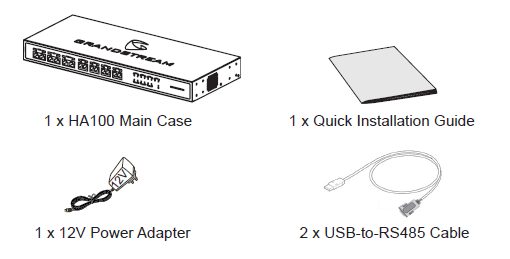
Package Contents
HA100 Interfaces
HA100 Front Panel
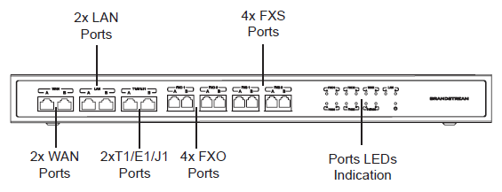
The front panel contains the internal HA100 ports:
- 1 pair of internal WAN ports (WAN-A, WAN-B).
- 1 pair of LAN ports (LAN-A, LAN-B).
- 1 pair of T1/E1/J1 ports (T1/E1/J1-A, T1/E1/J1-B).
- 2 pairs of internal FXS ports (FXS 1-A, FXS 1-B, FXS 2-A, FXS 2-B).
- 2 pairs of internal FXO ports (FXO 1-A, FXO 1-B, FXO 2-A, FXO 2-B).
HA100 Back Panel
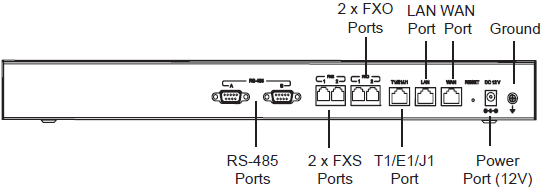
The back panel contains the external HA100 ports:
- 2 FXS ports.
- 2 FXO ports.
- 1 WAN port.
- 1 LAN port.
- 1 T1/E1/J1 port.
- 2 RS-485 Ports.
- 1 Power Port 12V.
- Reset Pin.
- Ground.
HA100 Connection
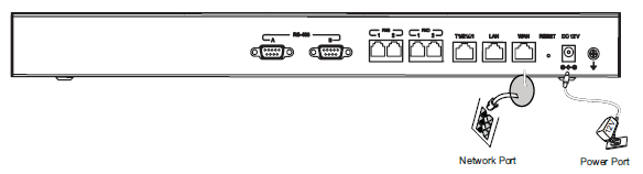
Powering and Connecting the HA100
Please refer to following steps for basic setup of the HA100:
- Connect one end of the Ethernet cable to the WAN port of the HA100 and the other end to the uplink port of a hub or switch.
- Connect the 12V power adapter jack to the power port on the HA100 and the plug end into an outlet.
Optional Connection
- For PSTN connection: Connect a PSTN cable to the FXO external port on HA100.
- For Analog phone/Fax connection: Connect analog phone or FAX machine to the FXS external port on HA100.
- For T1/E1/J1 connection: Connect T1/E1/J1 cable from the service provider side to the T1/E1/J1 external port on HA100.
- For LAN connection: Connect one end of the Ethernet cable to the LAN external port on HA100 and the other end to switch, hub or etc.
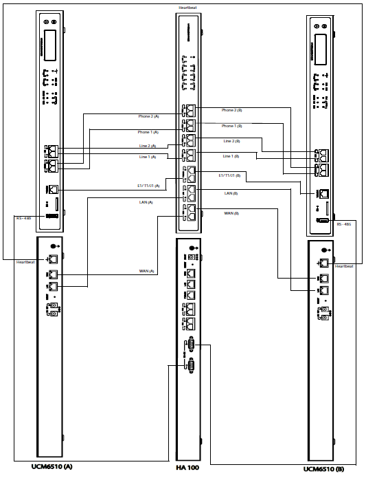
Connecting HA100 with 2 UCM6510
The following steps and diagram illustrate the connection between the HA100 and 2 UCM6510:
- Connect the Line port (FXO), Phone port (FXS), E1/T1/J1 port, WAN port and LAN port on UCM6510 A to the FXO-A port, FXS-A port, E1/T1/J1-A port, WAN-A port and LAN-A port on HA100.
- Use the USB-to-RS485 serial cable to connect UCM6510 A’s USB port to the RS485-A port on HA100.
- Connect the Line port (FXO), Phone port (FXS), E1/T1/J1 port, WAN port and LAN port on UCM6510 B to the FXO-B port, FXS-B port, E1/T1/J1-B port, WAN-B port and LAN-B port on HA100.
- Use the USB-to-RS485 serial cable to connect UCM6510 B’s USB port to the RS485-B port on HA100.
In this scenario, the HA100 separates the external port into the corresponding internal ports (A and B). By default, Port A is always connected, and Port B is always disconnected. Only one UCM device is connected at any given time. If the primary UCM (UCM6510 A) detects issues within itself, it will signal the HA100 via USB-to-RS485 cable to switch connection from Port A to Port B. The backup UCM (UCM6510 B) will then be successfully connected and resume service.
Please refer to following diagram for more details.