
Thank you for using Grandstream HA100. To meet the requirements of our customers, Grandstream has released the HA100, a module designed to implement the High Availability failover feature for our enterprise grade IP-PBX UCM6510.
It contains a set of external ports and splits each of them into two internal ports: Port A and Port B. The ports on the UCM6510 A and UCM6510 B should be connected to each Port A and Port B respectively. The external ports on the HA100 provide PBX service.
Powered by an advanced hardware platform and revolutionary software functionalities, the connection between the UCM6510 and HA100 offers a breakthrough turnkey solution for converged voice, video, data, fax, security surveillance, and mobility applications out of the box without any extra license fees or recurring costs.
Product Overview
Feature Highlights
The following list contain the major features of the HA100:
HA100 
|
|
HA100 Technical Specifications
Back Panel Interface | |
Analog Telephone FXS Ports | 2 ports |
PSTN Line FXO Ports | 2 ports |
T1/E1 Interface | 1 port |
Network Interfaces | 1 LAN/ 1 WAN |
RS-485 | 2, 1 for Primary UCM6510 and 1 for Secondary UCM6510 |
Reset Switch | Yes |
Universal Power Supply | DC 12V. |
Front Panel Interface | |
Analog Telephone FXS Ports | 4, 2 FXS A / 2 FXS B |
PSTN Line FXO Ports | 4, 2 FXO A / 2 FXO B |
T1/E1 Interface | 2 ports, T1/E1 A, T1/E1 B |
Network Interfaces | 2 LAN/ 2 WAN |
LED Indicators | Power, T1/E1, FXS, FXO, LAN, WAN |
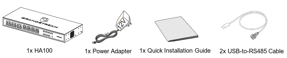
Equipment Packaging
The following items are included in the HA100 packaging:
Installation
Before deploying and configuring the HA100, the unit needs to be properly powered up and connected. This section describes detailed information about the HA100 interfaces and the steps needed for setting up the HA100.
HA100 Interfaces
The HA100 device has 24 ports, 1 reset button and 1 ground interface.
The 24 ports include 7 pairs of internal ports, 7 external ports, 2 RS485 ports and 1 power port.
HA100 Back Panel
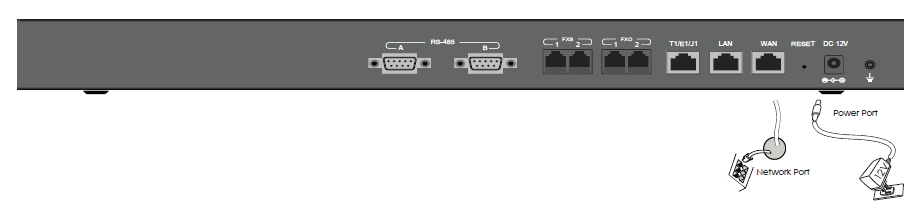
The following image illustrates the back panel of the HA100 containing the external ports:
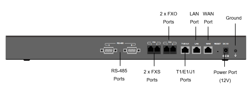
The back panel contains the following ports:
- 2 FXS ports.
- 2 FXO ports.
- 1 WAN port.
- 1 LAN port.
- 1 T1/E1/J1 port.
- 2 RS-485 ports.
HA100 Front Panel
The following image illustrates the front panel of the HA100 containing the internal ports:
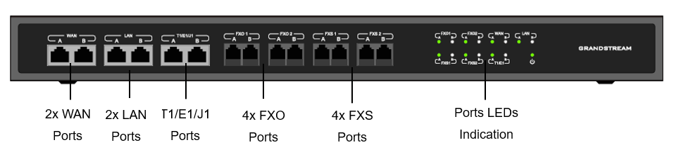
The front panel has the following ports:
- 1 pair of internal WAN ports (WAN-A, WAN-B)
- 1 pair of LAN ports (LAN-A, LAN-B)
- 1 pair of T1/E1/J1 ports (T1/E1/J1-A, T1/E1/J1-B)
- 2 pairs of internal FXS ports (FXS 1-A, FXS 1-B, FXS 2-A, FXS 2-B)
- 2 pairs of internal FXO ports (FXO 1-A, FXO 1-B, FXO 2-A, FXO 2-B)
RS-485 Interface
The HA100 has 2 RS485 ports on its back panel as displayed on the following image for defining and transmitting the electrical characteristics of drivers and receivers when using a serial communication.

LED Indicators
There is a total of 15 LED lights on HA100, including 1 power indicator and 7 pairs of internal port indicators.
- Power indicator:
Solid green once HA100 is powered on.
- Internal port indicator:
Each internal A and B port has a corresponding LED indicator. The LED indicator will be solid green when the internal port is connected to the UCM. For each pair of A/B ports, only 1 LED indicator will be solid green at one time.

HA100 Connection
This section provides the connection types and steps needed for connecting the HA100 with 2 UCM6510s’.
Powering and Connecting HA100
The external connections are used for the following purposes:
- Powering up the HA100
- Network connection
- PSTN lines connection
- Analog/Fax connection
- Digital (T1/E1/J1) connections.
Please refer to the following steps for basic connection setup of the HA100:
- Connect one end of an Ethernet cable to the WAN port of the HA100 and the other end of the cable to the uplink of a hub or switch.
- Connect 12V power adapter to the 12V power port on HA100 and the other end to a power outlet.
Optional Connections
Please refer to the following steps for optional connections on the HA100:
- For PSTN connection: Connect a PSTN cable to the FXO external port on HA100.
- For Analog phone/Fax connection: Connect analog phone or FAX machine to the FXS external port on HA100.
- For T1/E1/J1 connection: Connect your digital connection cable from the service provider side to the T1/E1/J1 external port on HA100.
- For LAN connection: Connect one end of the Ethernet cable to the LAN external port on HA100 and the other end to switch, hub or etc.
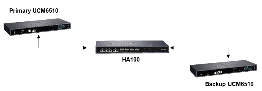
Connecting HA100 with 2x UCM6510s
In the connection between HA100 and 2x UCM6510s, one UCM6510 will function as the primary server and provide online services. The other UCM6510 will function as a backup server and will not provide services until the primary server is down.
Setup Requirements
The internal connection setup will require the following items:
- 5x RJ45 cables (Ethernet).
- 2x RJ48 cables (If using T1/E1/J1 trunk).
- 8x RJ11 cables (If using PSTN trunks and/or analog devices).
- 2x USB-to-RS485 serial cables.
- 2x UCM6510 (UCM A and UCM B) using firmware 1.0.15.13 or higher.
UCM6510 and HA100 Connection
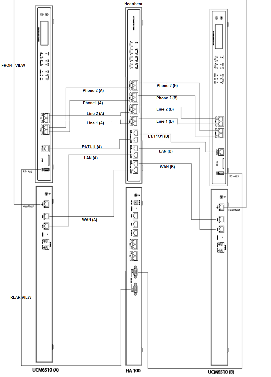
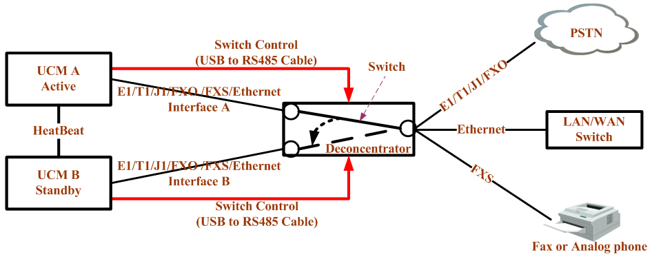
Please refer to followings steps for the basic internal connections between HA100, UCM A(Master) and UCM B(Slave):
- Connect respectively UCM A’s Line port (FXO), Phone port (FXS), E1/T1/J1 port, WAN port and LAN port to HA100’s FXO-A port, FXS-A port, E1/T1/J1-A port, WAN-A port, and LAN-A port.
- Use the USB-to-RS485 serial cable to connect UCM A’s USB port to the RS485-A port on HA100.
- Connect respectively UCM B’s Line port (FXO), Phone port (FXS), E1/T1/J1 port, WAN port and LAN port to HA100’s FXO-B port, FXS-B port, E1/T1/J1-B port, WAN-B port, and LAN-B port.
- Use the USB-to-RS485 serial cable to connect UCM B’s USB port to the RS485-B port on HA100.
- Use Ethernet cable to connect the Heartbeat ports on Primary UCM A and Backup UCM B.
The following diagram illustrates the connection between the HA100 and 2x UCM6510 PBXs.
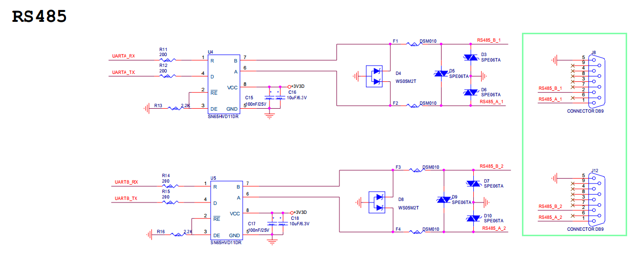
USB-to-RS485 Cable Pinout Information
In case the user cannot find or decides to make the USB to RS485 cable, please refer to the schematic below:
HA100 Deployment Methods
There are two deployment methods for adding an HA100 and a secondary UCM6510 to an existing UCM6510 setup:
Method 1: Backup and Restore Configuration
- Step 1: Upgrade UCM A to firmware version 1.0.15.13 or higher, and create a full backup (backup_A).
- Step 2: Upgrade UCM B to the same firmware as UCM A, and “backup_A” to UCM B. UCM A and UCM B should now have same configuration and data.
- Step 3: Connect all the cables as described in [UCM6510 and HA100 Connection] section “HA100 Connection”. Make sure all ports A in HA100 are connected to UCM A, and all ports B are connected to UCM B.
- Step 4: Make sure UCM A, UCM B and HA100 are up and running. Access UCM_A’s web UI, enable HA under System Settings🡪HA.
- Step5: Save and apply changes before rebooting.
Method 2: Sync Configuration
- Step 1: Upgrade UCM A to firmware version 1.0.15.13 or higher, then make a full backup (backup_A).
- Step 2: Upgrade UCM B to same firmware as UCM A.
- Step 3: Setup the connections as described in the [UCM6510 and HA100 Connection], EXCEPT heartbeat connection between UCM A and UCM B.
- Step 4: Access UCM_A’s web UI, enable HA under System Settings🡪HA and reboot UCM A.
- Step 5: Establish the heartbeat connection between UCM A and UCM B. UCM A should now sync its configuration to UCM B.
HA100 Configuration Settings on the UCM6510
Usage restriction:
- Both primary UCM6510 and secondary UCM6510 should be using the exact same firmware version.
- The connection between primary UCM6510 to HA100 and the connection between secondary UCM to HA100 must be correct. The heartbeat port must be connected correctly.
- It is recommended to use high performance switch or router to connect HA to.
- When powering up the HA100, the UCM6510 must be using static IP.
- When users need replace device, please reset the new devices before connecting to HA.
This section provides the configuration steps for the HA functionality on the UCM6510.
- Power up UCM6510(A), UCM6510(B) and HA100, after they boot up only the primary server UCM6510(A) can show the IP address.
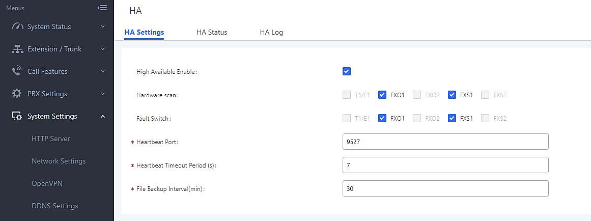
- Log in UCM6510(A) web UI and navigate to System Settings 🡪 HA 🡪 HA Settings
- Enable heartbeat, configure heart beat port and heart beat timeout. Users can also configure hardware scan and failure switchover.
Note :
- Hardware Scan (optional): select the hardware ports that to be detected for failure. Only the configured ports can be allowed to select here.
- Failure Switchover (optional): select the hardware ports to switch after failure is detected. Only the selected ports in “Hardware Scan” are available here.
- After the configuration, save and apply the change. The configuration will be sent to UCM6510(B) via heartbeat port and the two UCMs will reboot together.
The HA function has now started, if users need replace devices, it is recommended to reset the new devices first then connect into the setup.
HA100 Functionality
HA100 separates the external ports into the corresponding internal ports (A and B). Only one UCM6510 device is connected at any given time.
When the 2 UCM6510s connect to HA100 via port A and port B, the primary UCM6510 will use the external ports on HA100 for data transmission. The HA100’s RS485 port receives signaling from the UCM6510s to switch between Port A and Port B.
If the internal port A on HA100 is connected successfully to the corresponding port on primary UCM6510, the LED indicator for port A on HA100 will be solid green. The primary UCM6510 relies on HA100’s external ports for connections. In this case, the LED indicator for Port B on HA100 will not light up, and the backup UCM will not provide service.
For more details about UCM6510, please refer to online User Manual:
https://documentation.grandstream.com/knowledge-base/ucm6510-user-manual/
UCM6510 Failure Management
If the primary server (UCM6510 A) detects issues within itself, it will signal the HA100 via USB-to-RS485 cable to switch connection from Port A to Port B. The backup server (UCM6510 B) will then be successfully connected and resume service. If the primary server is suddenly down for any reason, the HA100 will automatically switch the connection from Port A to Port B, allowing the backup server (UCM6510) to resume services and minimizing the impact of the interruption.
HA100 Failure Management
The failure of HA100 will not cause the whole system to go down automatically.
The system will only go down if UCM master and UCM slave fail or UCM master and HA100 fail. For example, in a typical installation, UCM A is the master and UCM B is the slave. When HA100 goes down, it will not impact UCM A’s operation. And UCM A will detect that the HA100 is down and will send out alarm notifications via email. In this scenario, the whole network environment will be down if UCM A’s connections are lost. The HA100 setup should be reestablished before this happens.
Important Notes:
- When primary-secondary switchover happens, active calls will be cut off and cannot be recovered.
- Switchover will occur when both WAN or LAN connections are lost.
- When hardware scan and failure switchover are selected, the UCM will scan the selected interfaces. If failures are detected, the HA100 will perform primary-secondary switchover. For example, when hardware scan and failure switchover are selected for FXO, and the FXO cable is disconnected, it will trigger a switchover.
- For FXS port failure scan, the UCM will perform switchover only when there is an FXS chip hardware error and not when an FXS cable is disconnected.
- In a scenario where there is a persisting issue that triggers constant switchover, no switchovers will occur beyond the second one.
- Failure detection will detect only hardware failures.
- Data in external storage devices will not sync.
- If a switchover occurs, and UCM B assumes the Master role, UCM B will remain as Master until another switchover occurs.
- When upgrading UCM firmware, both UCM A and UCM B will be upgraded in the process. Both devices will reboot upon successful upgrade.
System Upgrade
Upgrading HA100
As we advise to always keep maintaining and upgrading the firmware on all your Grandstream devices, users could download the latest firmware version of HA100 module from the following link:
http://www.grandstream.com/support/firmware/
After this, please follow below steps in order to upgrade the unit:
- From the web GUI, navigate under the menu System Settings🡪HA🡪HA Settings and disable High Available.
- Ensure that the active UCM’s RS485 cable is connected to the HA device.
- Press the Reset button on the HA100 unit.
- Navigate under the menu System Settings🡪HA🡪HA Firmware Upgrade and Upload the downloaded firmware file.
Upgrading UCM6510s Connected to the HA100
The steps to upgrade both UCMs with an HA are the same as upgrading a single UCM.
- Ensure that all connections between the HA and the two UCMs are secure and working properly.
- Assuming that UCM A is the master and that UCM B is the slave, create a full backup of UCM A.
- From UCM A’s web portal, upgrade UCM A to the desired firmware. UCM B will also be upgrading during this time.
- Reboot the device when prompted. UCM B will automatically reboot alongside UCM A.
- Upon booting back up, UCM A and UCM B’s LCD displays should show “Master” and “Slave” respectively.
- Data syncing may occur for 5 or more minutes. If users cannot access the UCM web portal after booting up, please wait until the data sync is complete and try again.