
WELCOME
Thank you for purchasing Grandstream UCM6510 IP PBX appliance. The UCM6510 is an innovative IP PBX appliance for E1/T1/J1 networks that brings enterprise-grade unified communications and security protection to enterprises, small-to-medium businesses (SMBs), retail environments and residential settings in an easy-to-manage fashion. Powered by an advanced hardware platform and revolutionary software functionalities, the UCM6510 offers a breakthrough turnkey solution for converged voice, video, data, fax, security surveillance, and mobility applications out of the box without any extra license fees or recurring costs.
PRODUCT OVERVIEW
Feature Highlights
- 1 integrated E1/T1/J1 interface, 2 FXO ports, and 2 FXS ports with lifeline capability in case of power outage.
- Hardware DSP-based carrier-grade line echo cancellation (LEC) with 128ms-tail-length, hardware-based caller ID/call progress tone, and automatic impedance matching for various countries.
- Gigabit network ports with the LAN port supporting PoE, USB 2.0 port, SD card slot, and an integrated NAT router with advanced QoS support.
- Several protective measures against malicious attacks: Fail2Ban, whitelisting, blacklisting, alerts, etc.
- Data and data-voice communication via E1/T1/J1 with SS7/PRI.
- Supports up to 2000 SIP endpoint registrations, 200 concurrent calls (132 SRTP encrypted concurrent calls), and 64 conference participants.
- Offers flexible dial plans, call routing, site peering, and call recordings (manual/automatic for SIP calls).
- Functions as a central control panel for endpoints, integrated NTP server, and integrated LDAP contact directory.
- Automated detection and provisioning of supported IP phones, video phones, ATAs, gateways, SIP cameras, and others for simple and quick deployment
- Secure encryption with SRTP, TLS, and HTTPS with hardware encryption accelerator.
- Power redundancy and high availability via hot standby clustering.
- Scheduled backups and file cleaning for convenient maintenance.
TECHNICAL SPECIFICATION
|
Interfaces | |
|
Analog Telephone FXS Ports |
2x RJ11 ports with lifeline support Each port supports 2 REN |
|
PSTN Line FXO Ports |
2x RJ11 ports (with lifeline support) |
|
T1/E1/J1 Interface |
1x RJ45 port |
|
Network Interfaces |
1x Gigabit WAN port 1x Gigabit LAN port with PoE support 1x Gigabit port for Hot-Standby Clustering redundancy |
|
NAT Router |
Yes |
|
Peripheral Ports |
USB 2.0, SD |
|
LED Indicators |
Power 1/2, PoE, USB, SD, T1/E1/J1, FXS 1/2, FXO 1/2, LAN, WAN, Heartbeat |
|
LCD Display |
128×32 dot matrix graphic LCD with DOWN and OK buttons |
|
Reset Switch |
Yes, long press for factory reset and short press for reboot |
|
Voice/Video Capabilities | |
|
Voice-over-Packet Capabilities |
128ms tail-length carrier-grade Line Echo Cancellation with NLP Packetized Voice Protocol Unit, dynamic jitter buffer, modem detection, and auto-switch to G.711. |
|
Voice and Fax Codecs |
G.711 A-law/U-law, G.722, G.723.1 5.3K/6.3K, G.726, G.729A/B, OPUS, iLBC, GSM, RTX, AAL2-G.726-32, ADPCM; T.38 |
|
Video Codecs | H.264, H.263, H.263+, |
|
QoS |
Layer 3 QoS, Layer 2 QoS |
|
Signaling and Control | |
|
DTMF Methods |
Inband, RFC4733, and SIP INFO |
|
Digital Signaling |
PRI, SS7, MFC/R2, E&M |
|
Provisioning Protocol and Plug-and-Play |
TFTP/HTTP/HTTPS, auto-discovery & auto-provisioning of Grandstream IP endpoints via ZeroConfig (DHCP Option 66/multicast SIP SUBSCRIBE/ mDNS), Eventlist between local and remote trunks |
|
Network Protocols |
TCP/UDP/IP, RTP/RTCP, ICMP, ARP, DNS, DDNS, DHCP, NTP, TFTP, SSH, HTTP/HTTPS, PPPoE, SIP (RFC3261), STUN, SRTP, TLS, LDAP/LDAPS, HDLC, HDLC-ETH, PPP, Frame Relay |
|
Disconnect Methods |
Call Progress Tone, Polarity Reversal, Hook Flash Timing, Loop Current Disconnect, Busy Tone |
|
Security | |
|
Media |
SRTP, TLS 1.2, HTTPS, SSH |
|
Advanced Defense |
Fail2ban, alert events, whitelist, blacklist, strong password requirement. |
|
Physical | |
|
Universal Power Supply |
Input: 100-240VAC, 50-60Hz; Output: DC+12VDC, 1.5A |
|
Physical |
Unit Weight: 2.165 Kg; Package weight: 3.012 Kg |
|
Dimensions |
440mm (L) x 185mm (W) x 44mm (H) |
|
Environmental |
Operating: 32 – 113oF / 0 – 45oC, Humidity 10-90% (non-condensing) Storage: 14 – 140oF / -10 – 60oC, Humidity 10-90% (non-condensing) |
|
Mounting |
Rack mount |
|
Additional Features | |
|
Multi-language Support |
English, Simplified Chinese, Traditional Chinese, Spanish, French, Portuguese, German, Russian, Italian, Polish, Czech for Web GUI; Customizable IVR/voice prompts for English, Chinese, British English, German, Spanish, Greek, French, Italian, Dutch, Polish, Portuguese, Russian, Swedish, Turkish, Hebrew and Arabic |
|
Caller ID |
Bellcore/Telcordia, ETSI-FSK, ETSI-DTMF, SIN 227 – BT, NTT Japan |
|
Polarity Reversal/ Wink |
Yes, with enable/disable option upon call establishment and termination |
|
Call Center |
Multiple configurable call queues, automatic call distribution (ACD) based on agent skills/availability/busy level, in-queue announcement |
|
Customizable Auto Attendant |
Up to 5 layers of IVR (Interactive Voice Response) |
|
Maximum Call Capacity |
Up to 2000 registered SIP endpoints, up to 200 concurrent calls |
|
Conference rooms |
Up to 8 bridges, up to 64 simultaneous conference attendees |
|
Call Features |
Call park, call forward, call transfer, DND, DISA, ring group, pickup group, blacklist, paging/intercom and etc. |
|
Compliance |
|
INSTALLATION
Before deploying and configuring the UCM6510 series, the device needs to be properly powered up and connected to a network. This section describes detailed information on installation, connection and warranty policy of the UCM6510 series.
Equipment Packaging
|
UCM6510 Main Case |
1x |
|
Power Adapter |
2x |
|
Ethernet Cable |
1x |
|
Rack Mounts |
2x |
|
Screws |
8x |
|
Quick Installation Guide |
1x |
Connect your UCM6510
The following screenshots illustrate the front and back panels of the UCM6510:
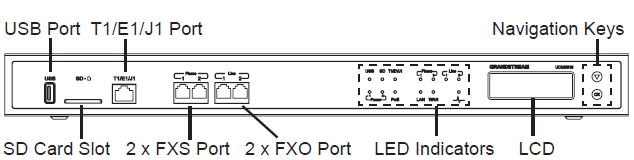
Follow the following steps to connect the UCM6510 for initial setup:
- Connect one end of an RJ-45 Ethernet cable (cable type: straight through) into the WAN port of the
UCM6510; connect the other end into the uplink port of an Ethernet switch/hub.
- Connect the 12V DC power adapter into one of the power jacks located on the back of the UCM6510. It is highly recommended to connect the other end of the plug to a surge protected power outlet. For power redundancy, connect a second 12V DC power adapter into the other power jack.
- Wait for the UCM6510 to boot up. The LCD in the front will show its hardware information when the bootup process is done.
- Once the UCM6510 is successfully connected to the network, the LED indicator for the WAN port in the front will be solid green, and the LCD will display the IP address.
Follow the steps below based on your environment:
- PSTN Line Connection: connect RJ11 cables from the wall jack to the UCM6510’s LINE ports (FXO ports).
- Analog Line Connection: connect RJ11 cables from phones or fax machines to the UCM6510’s PHONE ports (FXS ports).
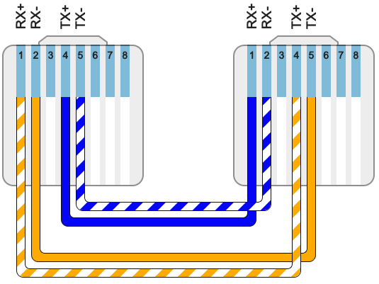
- T1/E1/J1 Line Connection: connect one end of the E1/T1/J1 cable into the UCM’s E1/T1/J1 port. Connect the other end to the appropriate port on legacy PBX systems. E1/T1/J1 crossover cables are not included in the UCM6510 packaging. Please see the following figure illustrating the crossover cable pin-out.:
Getting Started
To get started with the UCM6510 setup process, use the following available interfaces: LCD display, LED indicators, and web portal.
- The LCD display shows hardware, software, and network information and can be navigated via the DOWN and OK buttons next to the display. From here, users can configure basic network settings, run diagnostic tests, and factory reset.
- The LED indicators at the front of the device provides interface connection and activity status.
- The web portal (may also be referred to as web UI in this guide) is the primary method of configuring the UCM.
This section will provide step-by-step instructions on how to use these interfaces to quickly set up the UCM and start making and receiving calls with it.
Use The LCD Menu
- Idle Screen
Once the device has booted up completely, the LCD will show the UCM model, hardware version (e.g., V1.4A), and IP address. Upon menu key press timeout (15 seconds), the screen will default back to this information. Pressing the DOWN button will show the system time.
- Menu
Pressing the OK button will show the main menu. All available menu options are found in [Table 3: LCD Menu Options].
- Menu Navigation
Pressing the DOWN button will scroll through the menu options. Press the OK button to select an option.
- Exit
Selecting the Back option will return to the previous menu. For the Device Info, Network Info, and Web Info screens that have no Back option, pressing the OK button will return to the previous menu.
- LCD Backlight
The LCD backlight will turn on upon button press and will go off when idle for 30 seconds.
The following table shows the LCD menu options.
|
View Events |
|
|
Device Info |
|
|
Network Info |
|
|
Network Menu |
|
|
Factory Menu |
Press DOWN and OK buttons to scroll through and select different LCD patterns to test. Once a test is done, press the OK button to return to the previous menu.
Select Auto or On.
All On, All Off, and Blinking are the available options. Selecting Back in the menu will revert the LED indicators back to their actual status.
Select either 2022-02-22 22:22 or 2011-01-11 11:11 to start the RTC (Real-Time Clock) test pattern. Check the system time from either the LCD idle screen or in the web portal System Status->System Information->General page. To revert back to the correct time, manually reboot the device.
Select Test SVIP to verify hardware connections within the device. The result will display on the LCD when the test is complete. |
|
Web Info |
|
|
SSH Switch |
SSH access is disabled by default |
Use The LED Indicators
The UCM6510 has LED indicators in the front to display connection status. The following table shows the status definitions.
| LED Indicator | LED Status |
|---|---|
|
Power 1/Power 2 PoE LAN WAN USB SD Phone 1 /Phone 2 (FXS) Line 1/Line 2 FXO |
|
|
T1/E1/J1 |
|
Using the Web UI
Accessing the Web UI
The UCM’s web server responds to HTTP/HTTPS GET/POST requests. Embedded HTML pages allow users to configure the device through a web browser such Microsoft IE (version 8+), Mozilla Firefox, Google Chrome, etc. To access the UCM’s web portal, follow the steps below:
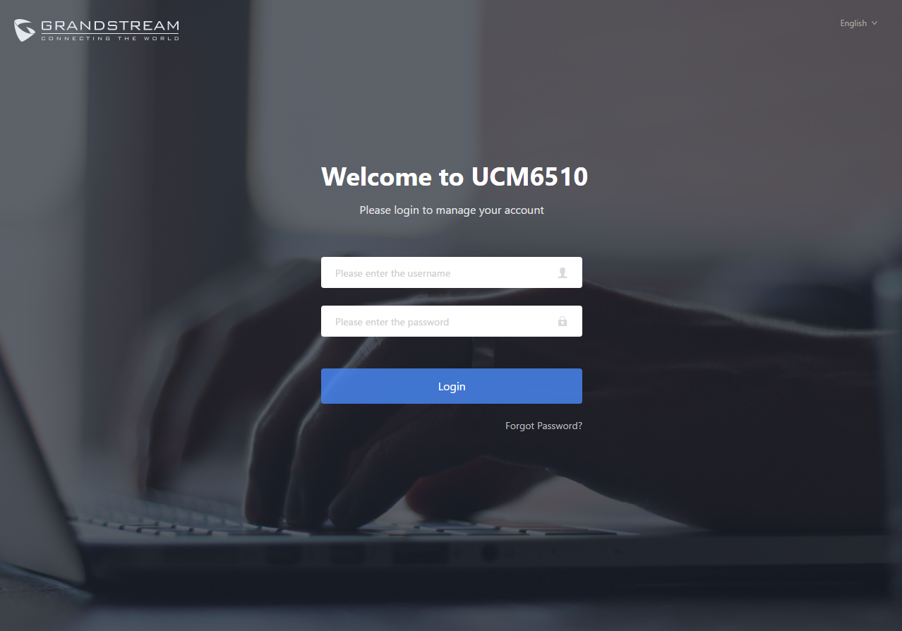
- Make sure your computer is on the same network as the UCM.
- Make sure that the UCM’s IP address is displayed on its LCD.
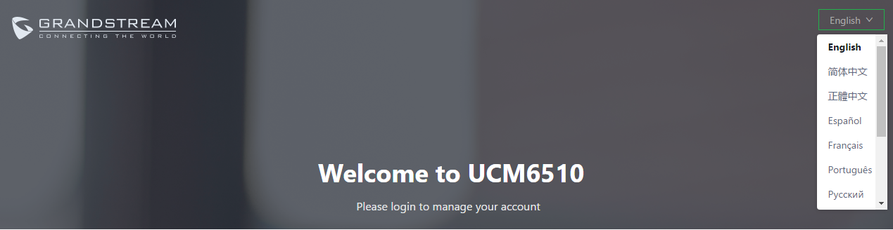
- Enter the UCM’s IP address into a web browsers’ address bar. The login page should appear (please see the above image).
- Enter default administrator username “admin” and password.
Setup Wizard
After logging into the UCM web portal for the first time, the setup wizard will guide the user through basic configurations such as time zone, network settings, trunks, and routing rules.
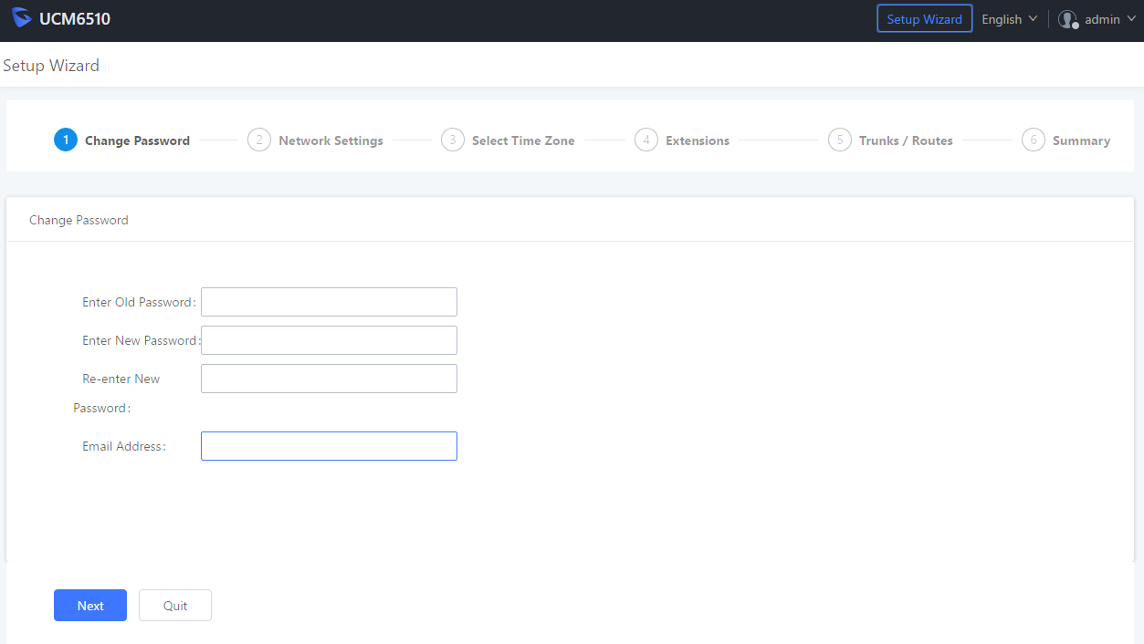
The setup wizard can be closed and reopened at any time. At the end of the wizard, a summary of the pending configuration changes can be reviewed before applying them.
Main Settings
There are 8 main sections in the web portal to manage various features of the UCM.
- System Status: Displays the dashboard, system information, current active calls, and network status.
- Extensions/Trunks: Manages extensions, trunks, and routing rules.
- Call Features: Manages various features of the UCM such as the IVR and voicemail.
- PBX Settings: Manages the settings related to PBX functionality such as SIP settings and interface settings.
- System Settings: Manages the settings related to the UCM system itself such as network and security settings.
- CDR: Contains the call detail records, statistics, and audio recordings of calls processed by the UCM.
- Value-Added Features: Manages the settings of features unrelated to core PBX functionality such as Zero Config provisioning and CRM/PMS integrations.
- Maintenance: Manages settings and logs related to system management and maintenance such as user management, activity logs, backup settings, upgrade settings and troubleshooting tools.
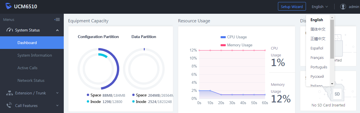
Web GUI Languages
Currently the UCM6510 Web GUI supports the following languages:
English, Simplified Chinese, Traditional Chinese, Spanish, French, Portuguese, Russian, Italian, Polish, Czech, German and Turkish.
Users can select the UCM’s web UI display language in the top-right corner of the page.
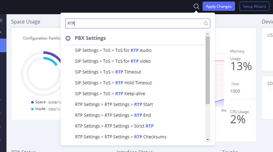
Web GUI Search Bar
Users can search for options in the web portal with the search bar on the top right of the page.
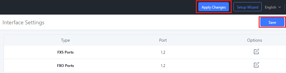
Saving and Applying Changes
After making changes to a page, click on the “Save” button to save them and then the “Apply Changes” button that appears to finalize the changes. If a modification requires a reboot, a prompt will appear asking to reboot the device.
Setting Up an Extension
Power on the UCM6510 and your SIP endpoint. Connect both devices to the same network and follow the steps below to set up an extension.
- Log into the UCM web portal and navigate to Extension/Trunk🡪Extensions
- Click on the “Add” button to start creating a new extension. The Extension and SIP/IAX Password information will be used to register to this extension. To set up voicemail, the Voicemail Password will be required.
- To register an endpoint to this extension, go into your endpoint’s web UI and edit the desired account. Enter the newly created extension’s number, SIP user ID, and password into their corresponding fields on the endpoint. Enter the UCM’s IP address into the SIP server field. If setting up voicemail, enter *97 into the Voice Mail Access Number field. This field may be named differently on other devices.
4. To access the extension’s voicemail, use the newly registered extension to dial *97 and access the personal voicemail system. Once prompted, enter the voicemail password. If successful, you will now be prompted with various voicemail options.
5. You have now set up an extension on an endpoint.
System Settings
This section will explain the available system-wide parameters and configuration options on the UCM6510. This includes settings for the following items: HTTP server, network, OpenVPN, DDNS, LDAP server, email server, and HA.
HTTP Server
The UCM6510’s embedded web server responds to HTTP/HTTPS GET/POST requests and allows users to configure the UCM via web browsers such as Microsoft IE, Mozilla Firefox, and Google Chrome. By default, users can access the UCM by just typing its IP address into a browser address bar. The browser will automatically be redirected to HTTPS using port 8089. For example, typing in “192.168.40.50” into the address bar will redirect the browser to “https://192.168.40.50:8089”. This behavior can be changed in the System Settings->HTTP Server page.
|
Redirect From Port 80 |
Toggles automatic redirection to UCM’s web portal from port 80. If disabled, users will need to manually add the UCM’s configured HTTP/HTTPS port to the server address when accessing the UCM web portal via browser. Default is “Enabled”. |
|
Protocol Type |
Select either HTTP or HTTPS as the protocol to access the UCM’s HTTP server. This will also determine what is used when endpoints download config files from the UCM via Zero Config. Default is “HTTPS”. |
|
Port |
Specifies the port number used to access the UCM HTTP server. Default is “8089”. |
|
If enabled, only the server addresses in whitelist will be able to access the UCM’s web portal. It is highly recommended to add the IP address currently used to access the UCM web page before enabling this option. Default is “Disabled”. | |
|
Permitted IP(s) |
List of addresses that can access the UCM web portal. Ex: 192.168.6.233 / 255.255.255.255 |
|
Selects the method of acquiring SSL certificates for the UCM web server. Two methods are currently available: – Upload Certificate: Upload the appropriate files from one’s own PC. – Request Certificate: Enter the domain for which to request a certificate for from Let’s Encrypt. | |
|
TLS Private Key |
Uploads the private key for the HTTP server. Note: Key file must be under 2MB in file size and in *.pem format. File name will automatically be changed to “private.pem”. |
|
TLS Cert |
Uploads the certificate for the HTTP server. Note: Certificate must be under 2MB in file size and in *.pem format. This will be used for TLS connections and contains private key for the client and signed certificate for the server. |
|
Domain |
Enter the domain to request the certificate for and click on |
If the protocol or port has been changed, the user will be logged out and redirected to the new URL.
Network Settings
After successfully connecting the UCM6510 to the network for the first time, users could log in the Web GUI and go to System Settings🡪Network Settings to configure the network parameters for the device. Select each tab in Web GUI🡪System Settings🡪Network Settings page to configure LAN/WAN settings, 802.1X and Port Forwarding.
Basic Settings
Please refer to the following tables for basic network configuration parameters on the UCM6510.
|
Method |
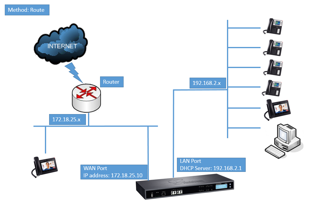
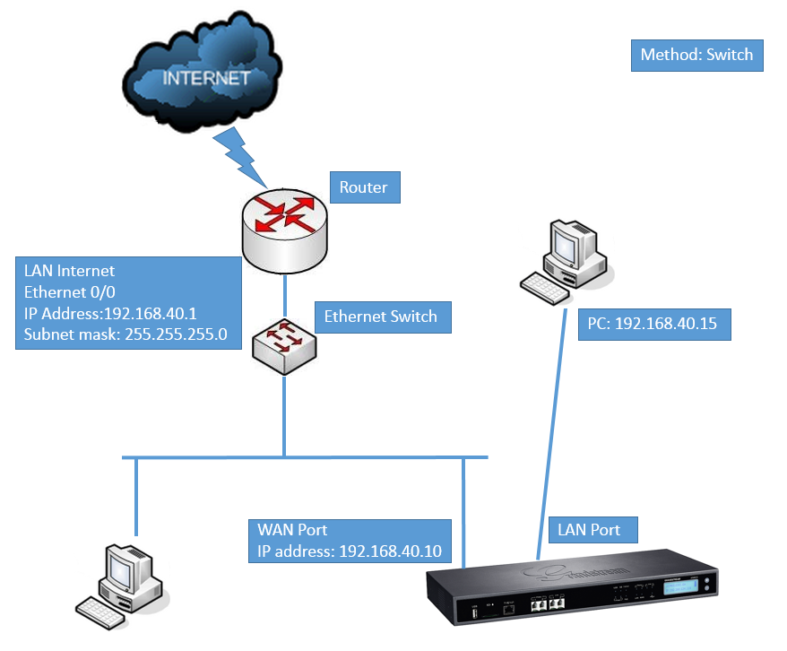
Select “Route”, “Switch” or “Dual” mode on the network interface of UCM6510. The default setting is “Route”.
WAN port will be used for uplink connection. LAN port will function similarly to a regular router port.
WAN port will be used for uplink connection. LAN port will be used as a bridge for connections.
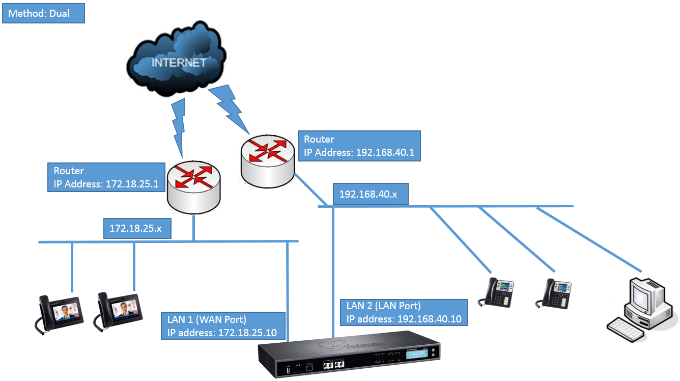
Both WAN and LAN ports will be used for uplink connections labeled as LAN2 and LAN1, respectively. The port selected as the Default Interface will need to have a gateway IP address configured if it is using a static IP. |
|
Specifies the maximum transmission unit value. Default is 1500. | |
|
IPv4 Address | |
|
Preferred DNS Server |
If configured, this will be used as the Primary DNS server. |
|
WAN (when “Method” is set to “Route”) | |
|
IP Method |
Select DHCP, Static IP, or PPPoE. The default setting is DHCP. |
|
IP Address |
Enter the IP address for static IP settings. The default setting is 192.168.0.160. |
|
Subnet Mask |
Enter the subnet mask address for static IP settings. The default setting is 255.255.0.0. |
|
Gateway IP |
Enter the gateway IP address for static IP settings. The default setting is 0.0.0.0. |
|
DNS Server 1 |
Enter the DNS server 1 address for static IP settings. The default setting is 0.0.0.0. |
|
DNS Server 2 |
Enter the DNS server 2 address for static IP settings. |
|
Username |
Enter the username to connect via PPPoE. |
|
Password |
Enter the password to connect via PPPoE. |
|
Layer 2 QoS 802.1Q/VLAN Tag |
Assign the VLAN tag of the layer 2 QoS packets for WAN port. The default value is 0. |
|
Layer 2 QoS 802.1p Priority Value |
Assign the priority value of the layer 2 QoS packets for WAN port. The default value is 0. |
|
LAN (when Method is set to “Route”) | |
|
IP Address |
Enter the IP address assigned to LAN port. The default setting is 192.168.2.1. |
|
Subnet Mask |
Enter the subnet mask. The default setting is 255.255.255.0. |
|
DHCP Server Enable |
Enable or disable DHCP server capability. The default setting is “Yes”. |
|
DNS Server 1 |
Enter DNS server address 1. The default setting is 8.8.8.8. |
|
DNS Server 2 |
Enter DNS server address 2. The default setting is 208.67.222.222. |
|
Allow IP Address From |
Enter the DHCP IP Pool starting address. The default setting is 192.168.2.100. |
|
Allow IP Address To |
Enter the DHCP IP Pool ending address. The default setting is 192.168.2.254. |
|
Default IP Lease Time |
Enter the IP lease time (in seconds). The default setting is 43200. |
|
LAN (when Method is set to “Switch”) | |
|
IP Method |
Select DHCP, Static IP, or PPPoE. The default setting is DHCP. |
|
IP Address |
Enter the IP address for static IP settings. The default setting is 192.168.0.160. |
|
Subnet Mask |
Enter the subnet mask address for static IP settings. The default setting is 255.255.0.0. |
|
Gateway IP |
Enter the gateway IP address for static IP settings. The default setting is 0.0.0.0. |
|
DNS Server 1 |
Enter the DNS server 1 address for static IP settings. The default setting is 0.0.0.0. |
|
DNS Server 2 |
Enter the DNS server 2 address for static IP settings. |
|
Username |
Enter the username to connect via PPPoE. |
|
Password |
Enter the password to connect via PPPoE. |
|
Layer 2 QoS 802.1Q/VLAN Tag |
Assign the VLAN tag of the layer 2 QoS packets for LAN port. The default value is 0. |
|
Layer 2 QoS 802.1p Priority Value |
Assign the priority value of the layer 2 QoS packets for LAN port. The default value is 0. |
|
LAN 1 / LAN 2 (when Method is set to “Dual”) | |
|
Default Interface |
If “Dual” is selected as “Method”, users will need assign the default interface to be LAN 1 (mapped to UCM6510 WAN port) or LAN 2 (mapped to UCM6510 LAN port) and then configure network settings for LAN1 and LAN 2. Default interface is LAN2. |
|
IP Method |
Select DHCP, Static IP, or PPPoE. The default setting is DHCP. |
|
IP Address |
Enter the IP address for static IP settings. The default setting is 192.168.0.160. |
|
Subnet Mask |
Enter the subnet mask address for static IP settings. The default setting is 255.255.0.0. |
|
Gateway IP |
Enter the gateway IP address for static IP settings when the port is assigned as default interface. The default setting is 0.0.0.0. |
|
DNS Server 1 |
Enter the DNS server 1 address for static IP settings. The default setting is 0.0.0.0. |
|
DNS Server 2 |
Enter the DNS server 2 address for static IP settings. |
|
Username |
Enter the username to connect via PPPoE. |
|
Password |
Enter the password to connect via PPPoE. |
|
Layer 2 QoS 802.1Q/VLAN Tag |
Assign the VLAN tag of the layer 2 QoS packets for LAN port. Default value is 0. |
|
Layer 2 QoS 802.1p Priority Value |
Assign the priority value of the layer 2 QoS packets for LAN port. The default value is 0. |
|
WAN (when “Method” is set to “Route”) | |
|
IP Method |
Select Auto or Static. The default setting is Auto |
|
IP Address |
Enter the IP address for static IP settings. |
|
IP Prefixlen |
Enter the Prefix length for static settings. Default is 64 |
|
DNS Server 1 |
Enter the DNS server 1 address for static settings. |
|
DNS Server 2 |
Enter the DNS server 2 address for static settings. |
|
LAN (when Method is set to “Route”) | |
|
DHCP Server |
Select Disable, Auto or DHCPv6. Disable: Disable the DHCPv6 server. Auto: Stateless address auto configuration using NDP protocol. DHCPv6: Stateful address auto configuration using DHCPv6 protocol. |
|
DHCP Prefix |
Enter DHCP prefix. (Default is 2001:db8:2:2::) |
|
DHCP prefixlen |
Enter the Prefix length for static settings. Default is 64 |
|
DNS Server 1 |
Enter the DNS server 1 address for static settings. Default is (2001:4860:4860::8888) |
|
DNS Server 2 |
Enter the DNS server 2 address for static settings. Default is (2001:4860:4860::8844) |
|
Allow IP Address From |
Configure starting IP address assigned by the DHCP prefix and DHCP prefixlen. |
|
Allow IP Address To |
Configure the ending IP address assigned by the DHCP Prefix and DHCP prefixlen. |
|
Default IP Lease Time |
Configure the lease time (in seconds) of the IP address. |
|
LAN (when Method is set to “Switch”) | |
|
IP Method |
Select Auto or Static. The default setting is Auto |
|
IP Address |
Enter the IP address for static IP settings. |
|
IP Prefixlen |
Enter the Prefix length for static settings. Default is 64 |
|
DNS Server 1 |
Enter the DNS server 1 address for static settings. |
|
DNS Server 2 |
Enter the DNS server 2 address for static settings. |
|
LAN 1 / LAN 2 (when Method is set to “Dual”) | |
|
Default Interface |
Users must select either LAN 1 (WAN port) or LAN 2 (LAN port) to be used as the default interface. Default setting is LAN 2. |
|
IP Method |
Select Auto or Static. The default setting is Auto |
|
IP Address |
Enter the IP address for static IP settings. |
|
IP Prefixlen |
Enter the Prefix length for static settings. Default is 64 |
|
DNS Server 1 |
Enter the DNS server 1 address for static settings. |
|
DNS Server 2 |
Enter the DNS server 2 address for static settings. |
- Method: Route
WAN port interface is used for uplink connection; LAN port interface is used as a router. Please see the sample diagram below.
- Method: Switch
WAN port interface is used for uplink connection; LAN port interface is used as bridge for PC connection.
- Method: Dual
Both WAN port and LAN port are used for uplink connection. WAN port will be mapped to LAN 1 interface; LAN port will be mapped to LAN 2 interface. Users will need assign LAN 1 or LAN 2 as the default interface in option “Default Interface” and configure “Gateway IP” if static IP is used for this interface.
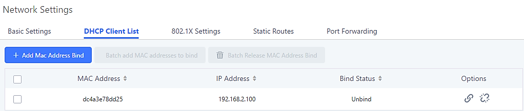
DHCP Client List
This page lists all the detected devices on the LAN and the IP addresses that were provided to them. Additionally, users can manually link a MAC address to an IP address.
When devices receive IP addresses from the UCM’s DHCP server, they will be listed in the System Settings🡪Network Settings🡪DHCP Client List page as shown below:
To manually add and bind a MAC address to an IP address, click on ![]() . The following menu will then be displayed.
. The following menu will then be displayed.
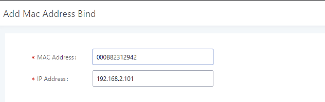
Enter the device’s MAC address and the IP address to bind it to. This IP address must be in the UCM’s DHCP range.
To bind multiple existing MAC addresses that are in the list to their respective IP addresses, check the boxes next to each MAC address and click on the ![]() button. A confirmation message will appear on the screen. Click
button. A confirmation message will appear on the screen. Click ![]() to bind the addresses.
to bind the addresses.
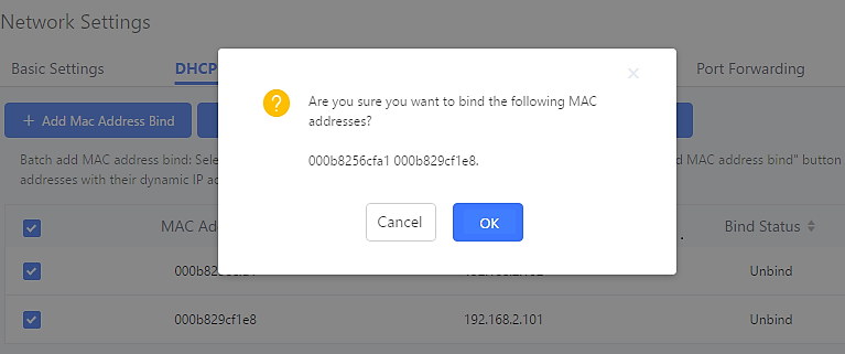
The Bind Status for the selected MAC addresses should now be changed from “Unbound” to “Bound”.
802.1X
IEEE 802.1X is an IEEE standard for port-based network access control. It provides an authentication mechanism to device before the device is allowed to access Internet or other LAN resources. The UCM6510 supports 802.1X as a supplicant/client to be authenticated.
The following diagram and figure show UCM6510 use 802.1X mode “EAP-MD5” on WAN port as client in the network to access Internet.
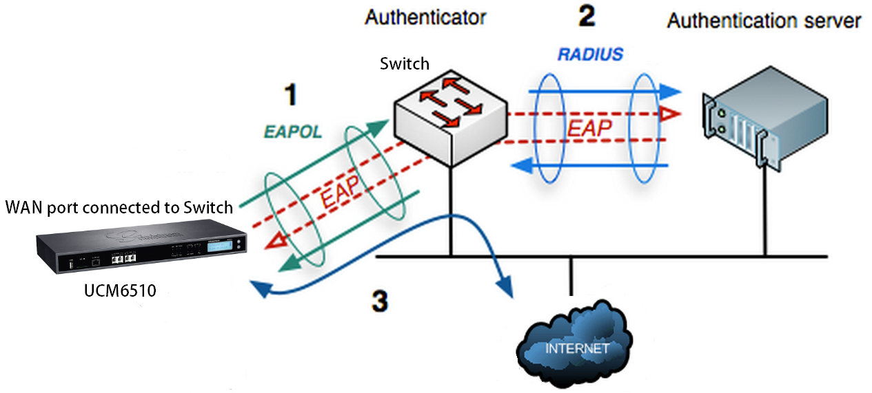
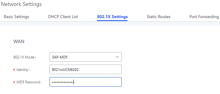
The following table shows the configuration parameters for 802.1X on UCM6510. Identity and MD5 password are required for authentication, which should be provided by the network administrator obtained from the RADIUS server. If “EAP-TLS” or “EAP-PEAPv0/MSCHAPv2” is used as the 802.1X mode, users will also need upload 802.1X CA Certificate and 802.1X Client Certificate, which should be also generated from the RADIUS server.
|
802.1X Mode |
Select 802.1X mode. The default setting is “Disable”. The supported 802.1X modes are:
|
|
Identity |
Enter 802.1X mode Identity information. |
|
MD5 Password |
Enter 802.1X mode MD5 password information. |
|
802.1X CA Certificate |
Select 802.1X certificate from local PC and then upload. |
|
802.1X Client Certificate |
Select 802.1X client certificate from local PC and then upload. |
Static Routes
A static route is a pre-determined path that the network traffic travels to reach a specific host or network. On the UCM6510, the static route function allows the device to use manually configured routes, instead of dynamically assigned routes or the default gateway. Static routes can be used to define a route when no others are available or can serve as complementary routes alongside existing routes as failover routes with existing routing on the UCM6510 as a failover backup, and etc.
- Click on
 to create a new IPv4 static route or click on
  to create a new IPv6 static route. The configuration parameters are listed in the table below.
 - Once added, users can select
 to edit the static route.
 - Select
 to delete the static route.
 - Static routes configuration can be reset from LCD menu🡪Network Menu.
|
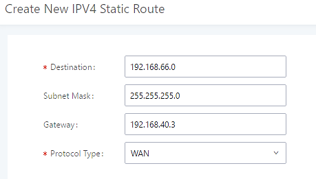
Destination |
Configure the destination IPv4 address or the destination IPv6 subnet for the UCM6510 to reach using the static route. Example: IPv4 address – 192.168.66.4 IPv6 subnet – 2001:740:D::1/64 |
|
Netmask |
Configure the subnet mask for the above destination address. If left blank, the default value is 255.255.255.255. Example: 255.255.255.0 |
|
Gateway |
Configure the IPv4 or IPv6 gateway address so that the UCM6510 can reach the destination via this gateway. Gateway address is optional. Example: 192.168.40.5 or 2001:740:D::1 |
|
Interface |
Specify the network interface “LAN”, “WAN” or “Data trunk 1” (“Data Trunk 1” option will show only when the data trunk is enabled) on the UCM6510 to reach the destination using the static route. |
The following diagram shows a sample application of static route usage on UCM6510.
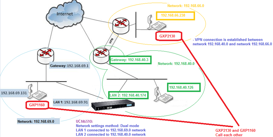
The network topology of the above diagram is as below:
- Network 192.168.69.0 has IP phones registered to UCM6510 LAN 1 address
- Network 192.168.40.0 has IP phones registered to UCM6510 LAN 2 address
- Network 192.168.66.0 has IP phones registered to UCM6510 via VPN
- Network 192.168.40.0 has VPN connection established with network 192.168.66.0
In this network, by default the IP phones in network 192.168.69.0 are unable to call IP phones in network 192.168.66.0 when registered on different interfaces on the UCM6510. Therefore, we need configure a static route on the UCM6510 so that the phones in isolated networks can make calls between each other.
Port Forwarding
The UCM network interface supports router functionality that allows users to configure port forwarding. If the UCM is set to “Route” in System Settings🡪Network Settings🡪Basic Settings🡪Method, the Port Forwarding tab will be available.
|
WAN Port |
Specify the WAN port number or a range of WAN ports. Unlimited number of ports can be configured. Note: When set to a range, both the WAN port and LAN port must be configured with the same range (e.g., WAN port: 1000-1005, LAN port: 1000-1005). Access from the WAN port will be forwarded to the LAN port with the same port number. |
|
LAN IP |
Specify the LAN IP address. |
|
LAN Port |
Specify the LAN port number or a range of LAN ports. Please see the note for WAN Port” instead of repeating the note. |
|
Protocol Type |
Select protocol type “UDP Only”, “TCP Only” or “TCP/UDP” for the forwarding in the selected port. The default setting is “UDP Only”. |
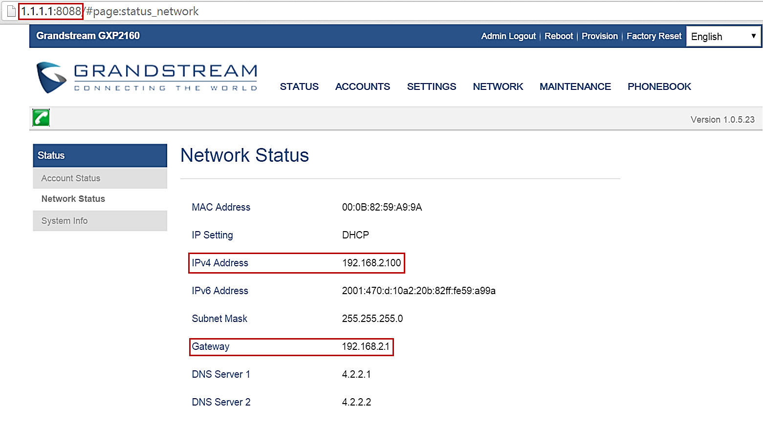
Here is an example of an environment and how to configure port forwarding to an endpoint’s web portal:
- Configure the UCM as a router by selecting “Route” in System Settings🡪Network Settings🡪Basic Settings🡪Method.
- WAN port is connected to an uplink switch with a public IP address configured (e.g., 1.1.1.1).
- LAN port provides a DHCP pool for devices on the LAN network (gateway address is 192.168.2.1 by default).
- Connect a GXP2160 to the UCM’s LAN network. It should obtain an IP address from UCM’s DHCP pool.
- While still on the Network Settings page, navigate to the Port Forwarding tab.
- Click on
 button to start setting up port forwarding.
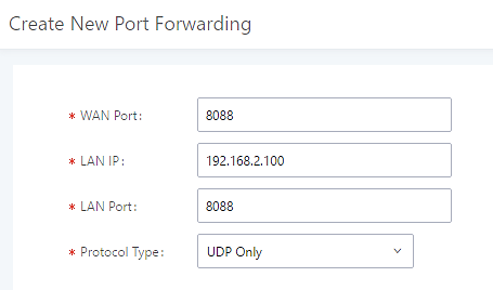
WAN Port: Enter the port that will be opened on the WAN side to allow access.
LAN IP: Enter the GXP2160’s IP address.
LAN Port: Enter the port that will be opened on the GXP2160 to allow access.
Protocol Type: Select the protocol to use for this port forwarding.
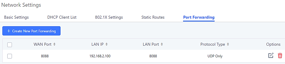
This will allow users to access the GXP2160 web portal from an external network.
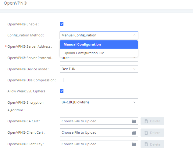
OpenVPN®
The UCM can be configured as an OpenVPN client.
DDNS Settings
Configuring UCM DDNS settings will allow the UCM to be accessed via domain name instead of IP address. UCM supports the following DDNS services:
- dydns.org
- noip.com
- freedns.afraid.org
- zoneedit.com
- oray.net
Below is an example of using noip.com for DDNS.
- Register the desired domain with the DDNS service provider. The UCM must be publicly accessible in order to work with the service provider.
- Navigate to System Settings🡪Network Settings🡪DDNS Settings, check the Enable DDNS option, select your service provider, and configure all the displayed fields.
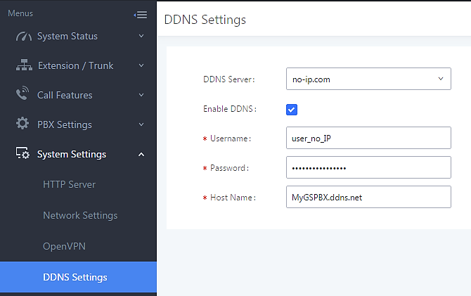
- You can now use the configured domain to access the UCM web portal.
Security Settings
The UCM offers several methods of protection against malicious attacks and unauthorized access such as firewall rules, connection thresholds, and Fail2ban.
To get started on configuring security settings, navigate to the System Settings🡪Security Settings page.
Static Defense
On the Static Defense page, users can configure firewall rules and view the ports used by various UCM services and processes.
The following table shows a few examples of the information available on the Static Defense page.
| Port | Process | Type |
|---|---|---|
|
7777 |
Asterisk |
TCP/IPv4 |
|
389 |
Slapd |
TCP/IPv4 |
|
22 |
Dropbear |
TCP/IPv4 |
|
80 |
Lighthttpd |
TCP/IPv4 |
|
8089 |
Lighthttpd |
TCP/IPv4 |
|
69 |
Opentftpd |
UDP/IPv4 |
|
9090 |
Asterisk |
UDP/IPv4 |
|
6060 |
zero_config |
UDP/IPv4 |
|
5060 |
Asterisk |
UDP/IPv4 |
|
4569 |
Asterisk |
UDP/IPv4 |
|
5353 |
zero_config |
UDP/IPv4 |
|
37435 |
Syslogd |
UDP/IPv4 |
For general firewall defense mechanisms, UCM supports Ping Defense, SYN-Flood Defense, and Ping-of-Death Defense. These can be configured separately for the WAN interface and LAN interface.
|
Ping Defense Enable |
If enabled, the UCM will not send ICMP messages in response to ping requests. |
|
If enabled, the UCM will limit the amount of SYN packets accepted from one source to 10 packets per second, preventing the UCM web portal from becoming inaccessible. Excess packets will be discarded. There is no need to mention the WAN and LAN parts since it is already mentioned in sentence before the table. | |
|
Ping-of-Death Defense Enable |
If enabled, the UCM will not be affected by ping of death attacks. |
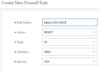
In the Custom Firewall Settings section, users can create rules to accept, reject, or drop specific traffic going through the UCM. To create a new rule, click on the [] button. To be consistent with the rest of the manual, get an image of the actual “Create New Rule” button.
Select the connection type to which the rule will apply to.
|
Rule Name |
Enter a name for the firewall rule. |
|
Action |
Select the action for the Firewall to perform.
|
|
Type |
Select the traffic type.
If selected, the Interface field will appear. Users must specify the interface that the inbound rule will be applied to.
|
|
Service |
Select the connection type the rule will apply to.
If selected, users must configure the Source IP and Port,Destination IP Address and Port, and the Protocol fields that appear. If the source and destination are left blank, the “Anywhere” values will be used. |
The new rule will be listed at the bottom of the page with sequence number, rule name, action, protocol, type, source, destination and operation. Users can click on ![]() to edit the rule or click on
to edit the rule or click on ![]() to delete the rule. The UCM must be rebooted for the new rules to take effect.
to delete the rule. The UCM must be rebooted for the new rules to take effect.
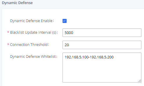
Dynamic Defense
On the Dynamic Defense page, users can configure the UCM to monitor incoming TCP connections and prevent excessive traffic from hosts. The UCM must have “Route” configured in the System Settings🡪Network Settings🡪Basic Settings page. The blacklist on this page is automatically updated. The following options are available:
|
Dynamic Defense Enable |
Toggle dynamic defense on and off. This is disabled by default. |
|
Blacklist Update Interval |
Configure the blacklist update time interval (in seconds). The default setting is 120. This defines how long the IP will be blocked once added into the UCM6510 blacklist. For example, if set to “300”, blocked IP addresses will not be able to establish TCP connections with the UCM until after 300 seconds have passed. |
|
Connection Threshold |
Configure the connection threshold. Once a host exceeds this threshold, it will be added to the blacklist. Default setting is 100. Reviewer Note: the “Periodic Time Interval” option is no longer available. |
|
Dynamic Defense Whitelist |
Allowed IPs and ports range, multiple IP addresses and port range. For example: 192.168.5.100 192.168.5.200 1500:2000 |
The following figure shows a configuration example like this:
- If a host at IP address 192.168.5.7 initiates more than 20 TCP connections to the UCM6510, it will be added into UCM6510 blacklist.
- This host 192.168.5.7 will be blocked by the UCM6510 for 5000 seconds.
- Since IP range 192.168.5.100-192.168.5.200 is in whitelist, if host initiates more than 20 TCP connections to the UCM6510, it will not be added into UCM6510 blacklist. It can still establish TCP connection with the UCM6510.
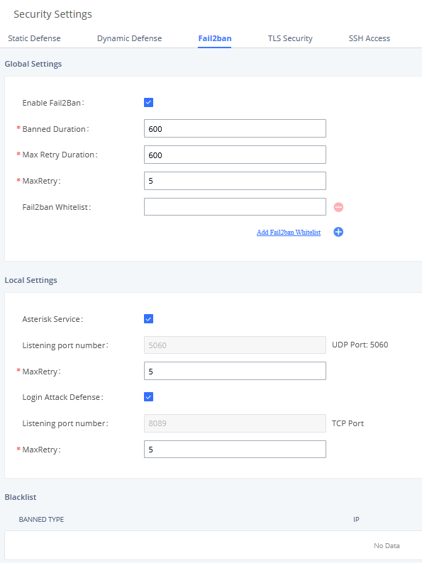
Fail2ban
Fail2Ban feature on the UCM6510 provides intrusion detection and prevention for authentication errors in SIP REGISTER, INVITE and SUBSCRIBE and prevents SIP brute force attacks on the PBX system. Once an IP address exceeds the allowed number of login or SIP authentication attempts within the configured “Max Retry Duration” period, all SIP and HTTP requests from that IP address will be dropped, forbidding web access and blocking further authentication attempts.
|
Global Settings | |
|
Enable Fail2Ban |
Enable Fail2Ban. The default setting is disabled. Please make sure both “Enable Fail2Ban” and “Asterisk Service” are turned on to use Fail2Ban for SIP authentication on the UCM6510. |
|
Banned Duration |
Configure the duration (in seconds) for the detected host to be banned. The default setting is 600. If set to 0, the host will be always banned. |
|
Max Retry Duration |
If a host exceeds the maximum allowed number attempts configured for Max Retry within the configured Max Retry Duration window, the host will be banned. The default setting is 600 seconds. |
|
MaxRetry |
Configures the maximum number of allowed authentication failures within the configured Max Retry Duration window. The default setting is 5. |
|
Configures the IP addresses, CIDR masks, and DNS hosts in the Fail2Ban whitelist. Whitelisted entries will not be banned by Fail2Ban even after exceeding the allowed number of authentication failures. Up to 20 addresses can be added. | |
|
Local Settings | |
|
Asterisk Service |
Enable Asterisk service for Fail2Ban. The default setting is disabled. Please make sure both “Enable Fail2Ban” and “Asterisk Service” are turned on to use Fail2Ban for SIP authentication on the UCM6510. |
|
Listening Port Number |
Configure the listening port number for the service. By default, port 5060 will be used for UDP and TCP, and port 5061 will be used for TLS. |
|
MaxRetry |
Configures the maximum number of authentication failures before the host is banned. The default setting is 10. Please note that this will override the Global Settings🡪MaxRetry setting. |
|
Enables defense against excessive login attacks to the UCM’s web GUI. The default setting is disabled. | |
|
Listening Port Number |
This is the Web GUI listening port number which is configured under System Settings🡪HTTP Server🡪Port. The default is 8089. |
|
MaxRetry |
Configures the maximum allowed number of failed login attempts from an IP address before it is added to the Fail2Ban blacklist. |
|
Blacklist | |
|
Blacklist |
Users will be able to view the IPs that have been blocked by UCM. |
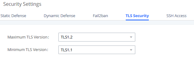
TLS Security
SSH access can be toggled from the UCM’s webUI and physical LCD screen. The webUI option can be found under System Settings🡪Security Settings-🡪SSH Access. SSH access is disabled by default and should only be turned on for troubleshooting and debugging.
SSH Access
SSH switch now is available via Web GUI and LCD. User can enable or disable SSH access directly from Web GUI or LCD screen. For web SSH access, please log in UCM6510 web interface and go to System Settings🡪Security Settings🡪SSH Access. By default, SSH access is disabled for security concerns. It is highly recommended to only enable SSH access for debugging purpose.
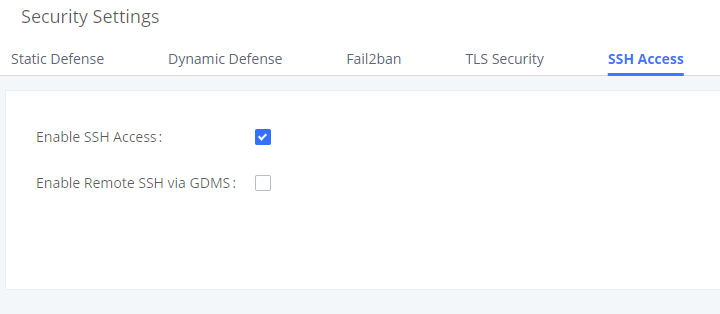
The option savailable under SSH Access tab:
- Enable SSH Access: This option is used for system debugging. Once enabled, UCM will allow SSH access. The SSH connection requires super administrator’s username and password. The default setting is “No”. It is recommended to set it to “No” if there is no need for debugging.
- Enable Remote SSH via GDMS: If this option is enabled, remote SSH access will be allowed through the GDMS platform. It is strongly recommended to keep this disabled unless remote troubleshooting is necessary.
LDAP Server
The UCM6510 has an embedded LDAP/LDAPS server for users to manage corporate phonebooks in a centralized manner.
- The LDAP server automatically generates an initial phonebook with PBX DN “ou=pbx,dc=pbx,dc=com” based on the UCM6510’s existing extensions.
- Users could add new phonebook with a different Phonebook DN for other external contacts. For example, “ou=people,dc=pbx,dc=com”.
- All the phonebooks in the UCM6510 LDAP server have the same Base DN “dc=pbx,dc=com”.
- “cn” “ou” and “dc” are parts of LDAP data Interchange Format according to RFC2849, which is how the LDAP tree is filtered.
Cn= Common Name
ou= Organization Unit
dc= Domain Component
- Here is an example of how the search for “ou=pbx,dc=pbx,dc=com” is performed in LDAP server query.
From the dc=com Domain Component, find the dc=pbx Domain Component first. In the dc=pbx Domain Component, find the Organizational Unit called pbx (ou=pbx) and then find the object that has a Common Name of admin.
If users have the Grandstream phone provisioned by the UCM6510, the LDAP directory has been set up on the phone and can be used right away for users to access all phonebooks generated in the UCM6510.
Additionally, users could manually configure the LDAP client settings to manipulate the built-in LDAP server on the UCM6510. If the UCM6510 has multiple LDAP phonebooks created, in the LDAP client configuration, users could use “dc=pbx,dc=com” as Base DN to have access to all phonebooks on the UCM6510 LDAP server, or use a specific phonebook DN, for example “ou=people,dc=pbx,dc=com”, to access to phonebook with Phonebook DN “ou=people,dc=pbx,dc=com “ only.
To access LDAP Server settings, go to Web GUI🡪System Settings🡪LDAP Server.
LDAP Server Configurations
The following figure shows the default LDAP/LDAPS server configurations on the UCM6510.
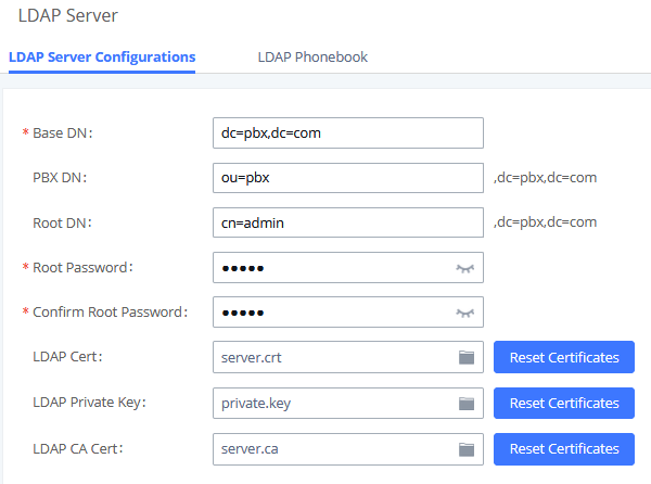
The UCM6510 LDAP/LDAPS server supports anonymous access (read-only) by default. Therefore, the LDAP client does not have to configure username and password to access the phonebook directory. The “Root DN” and “Root Password” (limited with 64 and 32 characters respectively) here are for LDAP management and configuration where users will need provide for authentication purpose before modifying the LDAP information.
The default phonebook list in this LDAP server can be viewed and edited by clicking on ![]() for the first phonebook under LDAP Phonebook.
for the first phonebook under LDAP Phonebook.

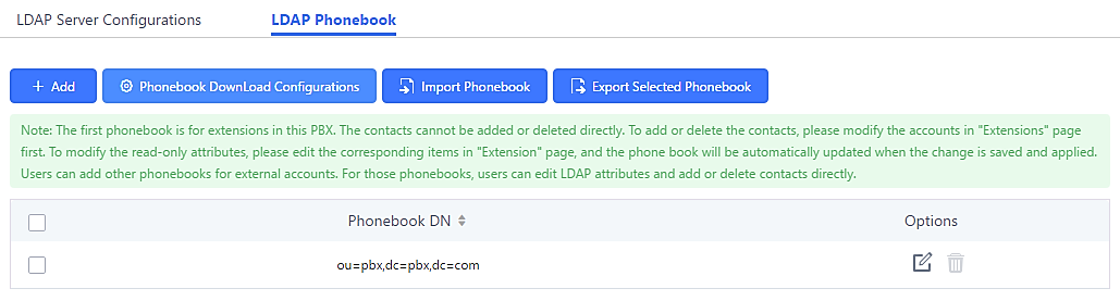
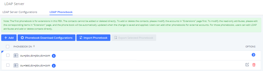
LDAP Phonebook
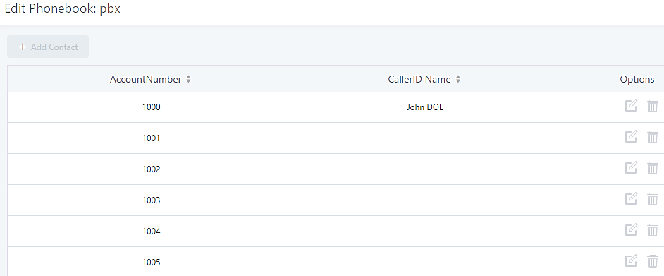
Users could use the default phonebook, edit the default phonebook as well as add new phonebook on the LDAP server. The first phonebook with default phonebook dn “ou=pbx,dc=pbx,dc=com” displayed on the LDAP server page is for extensions in this PBX. Users cannot add or delete contacts directly. The contacts information will need to be modified via Web GUI🡪Extension/Trunk🡪Extensions first. The default LDAP phonebook will then be updated automatically.
- Add new phonebook
A new sibling phonebook of the default PBX phonebook can be added by clicking on “Add” under “LDAP Phonebook” section.
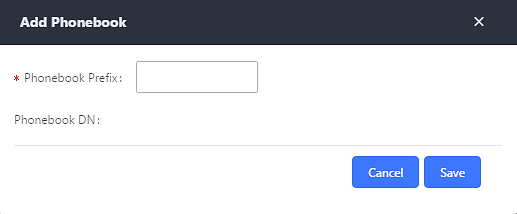
Configure the “Phonebook Prefix” first. The “Phonebook DN” will be automatically filled in. For example, if configuring “Phonebook Prefix” as “people”, the “Phonebook DN” will be filled with “ou=people,dc=pbx,dc=com”.
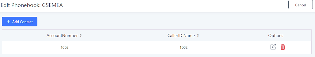
Once added, users can select ![]() to edit the phonebook attributes and contact list (see figure below) or select
to edit the phonebook attributes and contact list (see figure below) or select ![]() to delete the phonebook.
to delete the phonebook.
- Import phonebook from your computer to LDAP server
Click on “Import Phonebook” and a dialog will prompt as shown in the figure below.
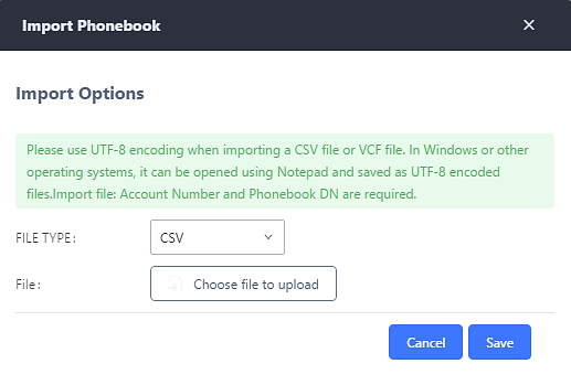
The file to be imported must be a CSV, VCF or XML file with UTF-8 encoding. Users can open the file with Notepad and save it with UTF-8 encoding.
Here is an example CSV file. Please note “Account Number” and “Phonebook DN” fields are required. Users can export a phonebook file from the UCM’s LDAP phonebook section and use it as a template.
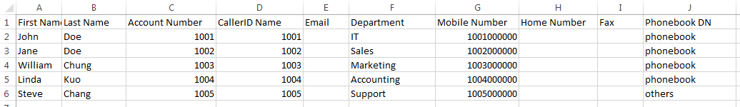
The Phonebook DN field is the same “Phonebook Prefix” entry as when the user clicks on “Add” to create a new phonebook. Therefore, if the user enters “phonebook” in “Phonebook DN” field in the CSV file, the actual phonebook DN “ou=phonebook,dc=pbx,dc=com” will be automatically created by the UCM6510 once the CSV file is imported.
In the CSV file, users can specify different phonebook DN fields for different contacts. If the phonebook DN already exists on the UCM6510 LDAP Phonebook, the contacts in the CSV file will be added into the existing phonebook. If the phonebook DN does not exist on the UCM6510 LDAP Phonebook, a new phonebook with this phonebook DN will be created.
The sample phonebook CSV file in above picture will result in the following LDAP phonebook in the UCM6510.
As the default LDAP phonebook with DN “ou=pbx,dc=pbx,dc=com” cannot be edited or deleted in LDAP phonebook section, users cannot import contacts that have “pbx” in the Phonebook DN field of the CSV file.
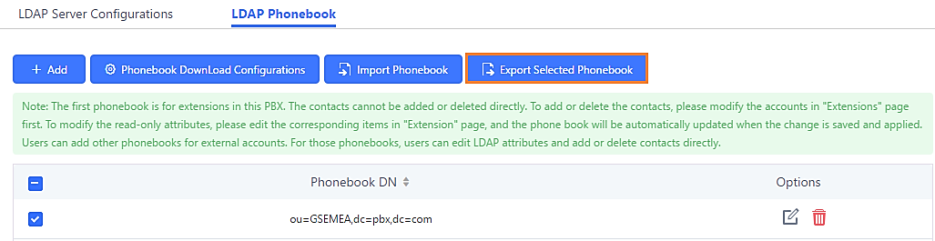
- Export phonebook to your computer from UCM6510 LDAP server
Select the checkbox for the LDAP phonebook and then click on “Export Selected Phonebook” to export the selected phonebook. The exported phonebook can be used as a record or a sample CSV, VFC or XML file for the users to add more contacts in it and import to the UCM6510 again.
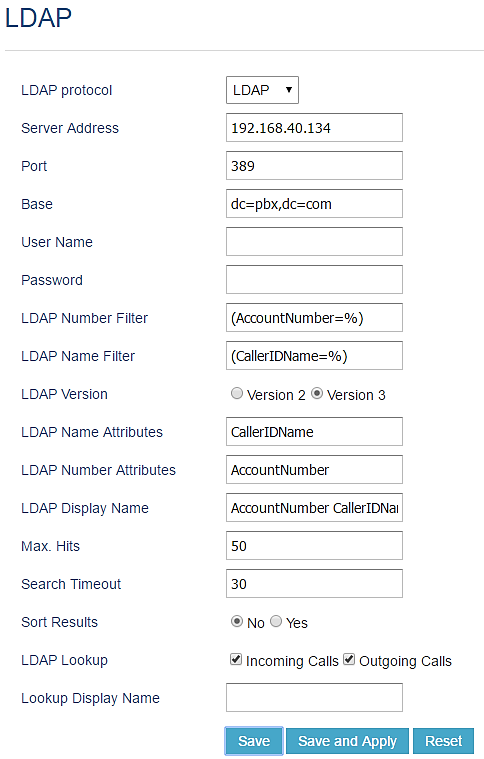
LDAP Client Configurations
The configuration on LDAP client is useful when you use other LDAP servers. Here we provide an example on how to configure the LDAP client on the UCM.
Assuming the remote server base dn is “dc=pbx,dc=com”, configure the LDAP client as follows:
- LDAP Server: Enter a name for the remote LDAP server
- Server Address: Enter the IP address or domain name for remote LDAP server.
- Base DN: dc=pbx,dc=com
- Username: Enter username if authentication is required. This field cannot exceed 64 characters and can contain space.
- Password: Enter password if authentication is required.
- Filter: Enter the filter. Ex: (|(CallerIDName=%)(AccountNumber=%))
- Port: Enter the port number. Ex:389
- LDAP Name Attributes: Enter the name attributes for remote server
- LDAP Number Attributes: Enter the number attributes for remote server
- Client type: Protocol of LDAP or LDAPS.
- LDAP Client CA cert: Upload LDAP client CA certificate, The following file types are supported: .crt .der and .pem.
- LDAP Client Private Key: Upload LDAP client private key.
The following figure gives a sample configuration for UCM6510 acting as an LDAP client.
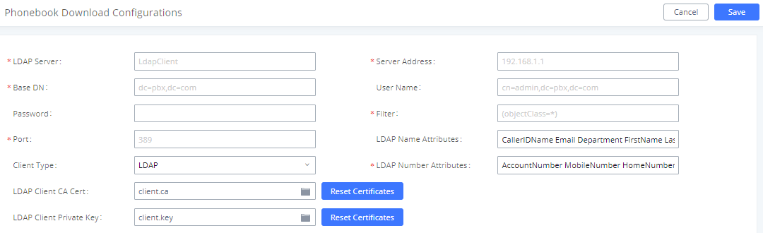
To configure Grandstream IP phones as the LDAP clients for UCM, please refer to the following example:
- Server Address: The IP address or domain name of the UCM6510
- Base DN: dc=pbx,dc=com
- Username: Please leave this field empty
- Password: Please leave this field empty
- LDAP Name Attribute: CallerIDName Email Department FirstName LastName
- LDAP Number Attribute: AccountNumber MobileNumber HomeNumber Fax
- LDAP Number Filter: (AccountNumber=%)
- LDAP Name Filter: (CallerIDName=%)
- LDAP Display Name: AccountNumber CallerIDName
- LDAP Version: If existed, please select LDAP Version 3
- Port: 389
The following figure shows the configuration information on a Grandstream GXP2170 to successfully use the LDAP server as configured in [Figure 31: LDAP Server Configurations].
Time Settings
Automatic Date and TIme
The current system time can be found under System Status🡪Dashboard and System Information.
To configure the UCM to automatically update time, navigate to System Settings🡪Time Settings🡪Automatic Date and Time.
|
Specify the server address of the NTP server for the UCM6510 to sync date and time with. The default NTP server is pool.ntp.org. | |
|
Enable DHCP Option 2 |
If set to “Yes”, the UCM’s time zone can be provisioned via DHCP Option 2 from a local server automatically. |
|
Enable DHCP Option 42 |
If set to “Yes”, the UCM’s NTP server can be provisioned via DHCP Option 42 from a local server automatically. This will override the manually configured NTP server. The default setting is “Yes”. |
|
Select the time zone for the UCM to use. If “Self-Defined Tome Zone” is selected, please specify the time zone parameters in “Self-Defined Time Zone” field as described in below option. | |
|
Self-Defined Time Zone |
If “Self-Defined Time Zone” is selected in “Time Zone” option, users will need define their own time zone following the format below. The syntax is: std offset dst [offset], start [/time], end [/time] Default is set to: MTZ+6MDT+5,M4.1.0,M11.1.0 MTZ+6MDT+5 This indicates a time zone with 6 hours offset and 1 hour ahead for DST, which is U.S central time. If it is positive (+), the local time zone is west of the Prime Meridian (A.K.A: International or Greenwich Meridian); If it is negative (-), the local time zone is east. M4.1.0,M11.1.0 The 1st number indicates Month: 1, 2, 3…, 12 (for Jan, Feb…Dec.). The 2nd number indicates the nth iteration of the weekday: (1st Sunday, 3rd Tuesday…). Normally 1, 2, 3, 4 are used. If 5 is used, it means the last iteration of the weekday. The 3rd number indicates weekday: 0, 1, 2…6 (for Sun, Mon, Tues… Sat). Therefore, this example is the DST which starts from the First Sunday of April to the 1st Sunday of November. |
Set Date and Time
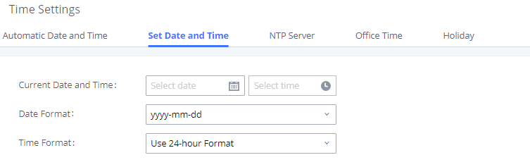
To manually set the time on the UCM6510, go to Web GUI🡪System Settings🡪Time Settings🡪Set Date and Time. The format is YYYY-MM-DD HH:MM:SS.
NTP Server
The UCM can act as an NTP server for clients to sync their system times with. To configure this, navigate to System Settings🡪Time Settings🡪NTP Server and set Enable NTP Server to “Yes”. On the client side, use the UCM’s IP address or hostname as the NTP server address.
Office Time
The system administrator can define office hours which can be used as conditions for call forwarding and inbound routing. To configure this, navigate to System Settings🡪Time Settings🡪Office Time and click on the Add button to create office hours.
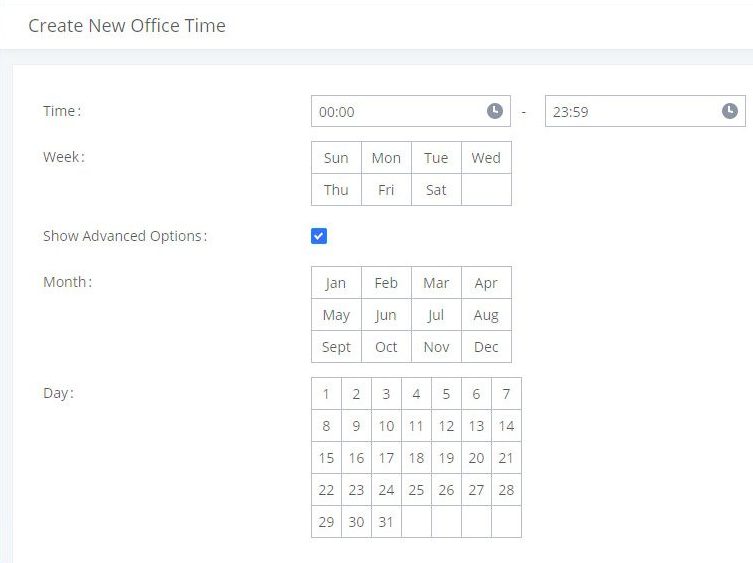
|
Start Time |
Configure the start time for office hour. |
|
End Time |
Configure the end time for office hour |
|
Week |
Select the workdays in one week. |
|
Show Advanced Options |
Check this option to show advanced options. Once selected, please specify “Month” and “Day” below. |
|
Month |
Select the months for office time. |
|
Day |
Select the workdays in one month. |
Select “Start Time”, “End Time” and the day for the “Week” for the office time. The system administrator can also define month and day of the month as advanced options. Once done, click on “Save” and then “Apply Change” for the office time to take effect. The office time will be listed in the web page as the figure shows below.
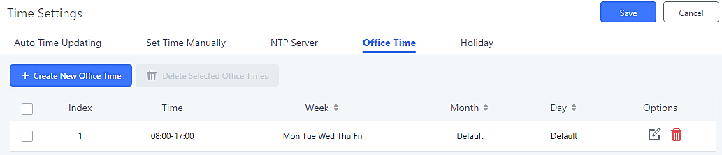
- Click on to edit the office time.
- Click on to delete the office time.
- Click on “Delete Selected Office Times” to delete multiple selected office times at once.
Holiday
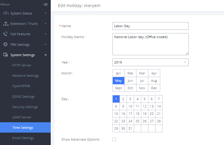
System administrators can define holidays which can be used as conditions for call forwarding and inbound routing. To configure this, navigate to System Settings🡪Time Settings🡪Holiday and click on the Add button to create a new holiday.
|
Name |
Specify the holiday name to identify this holiday. |
|
Holiday Memo |
Create a note for the holiday. |
|
Select the year of the Holiday. | |
|
Month |
Select the month for the holiday. |
|
Day |
Select the day for the holiday. |
|
Show Advanced Options |
Check this option to show advanced options. If selected, please specify the days as holiday in one week below. |
|
Week |
Select the days as holiday in one week. |
Enter holiday “Name” and “Holiday Memo” for the new holiday. Then select “Month” and “Day”. The system administrator can also define days in one week as advanced options. Once done, click on “Save” and then “Apply Change” for the holiday to take effect. The holiday will be listed in the web page as the figure shows below.
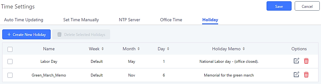
- Click on to edit the holiday.
- Click on to delete the holiday.
- Click on “Delete Selected Holidays” to delete multiple selected holidays at once.
Email Settings
Email Settings
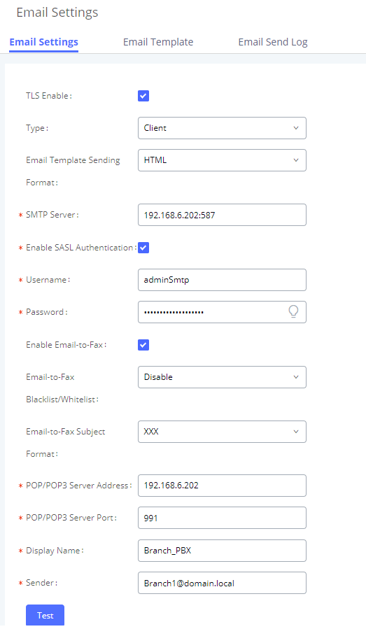
The UCM’s email module can send out alert event emails, fax (Fax-to-Email), voicemail (Voicemail-to-Email), etc. Email settings can be configured in System Settings🡪Email Settings.
|
TLS Enable |
Enable or disable TLS during transferring/submitting your email to another SMTP server. The default setting is “Yes”. |
|
Type |
|
|
Domain |
Specify the domain name to be used in the Email when using type “MTA”. |
|
Server |
Specify the SMTP server when using type “Client”. For example, if using Gmail as the SMTP server, you can configure it as smtp.gmail.com:465. |
|
Username is required when using type “Client”. This is typically the email address. | |
|
Password for the entered Username. | |
|
Toggles the Email-to-Fax feature. If enabled, the UCM will monitor the configured email inbox (using provided [Username] and [Password]) for emails with the subject “SendFaxMail To XXX“. Example : SendFaxMail To 7200 The UCM will extract the attachments of detected emails and send it to the XXX extension by fax. The attachment must be in PDF/TIF/TIFF format. Note: This field will appear when using Type “Client”. | |
|
Enables Email-to-Fax Blacklist/Whitelist functionality. | |
|
Specify the Email subject format for fax sending, the subject can be either “SendFaxMail To XXX” or “XXX” with XXX the fax number. | |
|
Internal Blacklist/Whitelist |
Specify the Email address blacklist/whitelist for local extensions. This feature prevents faxing from unauthorized email addresses. The internal list includes only contacts with local extensions |
|
External Blacklist/Whitelist |
Specify the Email address blacklist/whitelist for non-local contacts. This feature prevents faxing from unauthorized email addresses. The external list is for non-local contacts. Note: Multiple addresses can be separated with semicolon (;) i.e. ” XXX;YYY “. |
|
POP/POP3 Server Address |
Configure the POP/POP3 server address for the configured username |
|
POP/POP3 Server Port |
Configure the POP/POP3 server port for the configured username |
|
Display Name |
Specify the display name in the FROM header in the Email. |
|
Sender |
Specify the sender’s Email address. For example: pbx@example.mycompany.com. |
The following figure shows example email settings, where 192.168.6.202 is the SMTP server.
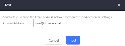
Once configuration is complete, click on the Save button first and then the Test button to verify that the settings work.
The following figure shows the new dialog prompted to test the Email setting. Fill in a valid Email address to send a test Email to verify the Email settings on the UCM6510.
Email Templates
The UCM provides various email templates for different email notifications. Email templates can be accessed from System Settings🡪Email Settings🡪Email Templates.
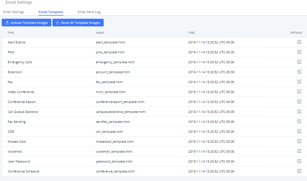
Press on ![]() to upload pictures to be used on email templates.
to upload pictures to be used on email templates.
Press ![]() to reset all email templates to default ones.
to reset all email templates to default ones.
To configure the email template, simply click the ![]() button under Options column, and edit the template as desired.
button under Options column, and edit the template as desired.
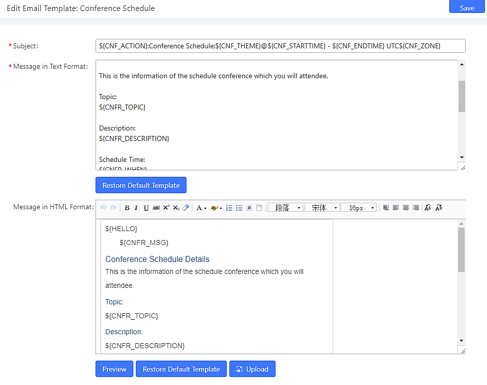
- Users can preview mail sample by clicking on
 .
. - Click on
 to restore the default email template.
 - Finally, users can click on
 to upload a custom picture to the email template to display their own logo in the sent mails for example
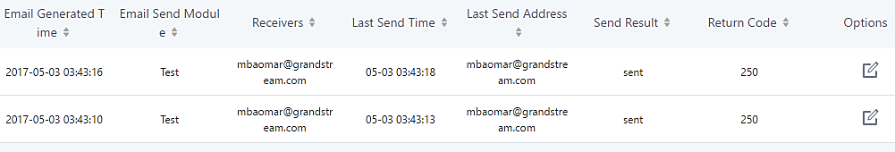
Email Send Log
Under UCM Web GUI🡪System Settings🡪Email Settings🡪Email Send Log, users could search, filter and check whether the Email is sent out successfully or not. This page will also display the corresponding error message if the Email is not sent out successfully.
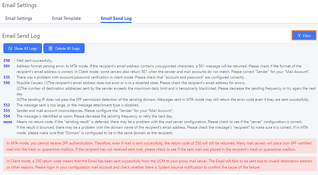
| Field | Description |
|---|---|
|
Start Time |
Enter the start time for filter |
|
End Time |
Enter the end time for filter |
|
Receivers |
Enter the email recipient, while searching for multiple recipients, please separate then with comma and no spaces. |
|
Send Result |
Enter the status of the send result to filter with |
|
Return Code |
Enter the email code to filter with |
|
Select the email module to filter with from the drop-down list, which contains:
|
Email logs will be shown on bottom of “Email Send Log” page, as shown on the following figure.
Recordings Storage
The UCM supports both automatic and manual call recordings. Recordings can be saved to UCM’s local storage, external storage (SD/USB disks), and NAS.
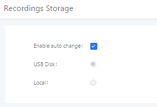
- If “Enable Auto Change” is selected, the recording storage location will automatically change to NAS, USB Disk, or SD card if they are available. If all storage location types are available, the priority will be NAS->USB Disk->SD Card->Local storage.
- If “Local” is selected, the recordings will be stored in UCM6510 internal storage.
- If “USB Disk” or “SD Card” is selected, the recordings will be stored in the corresponding plugged in external storage device. Please note the options “USB Disk” and “SD Card” will be displayed only if they are plugged into the UCM6510.
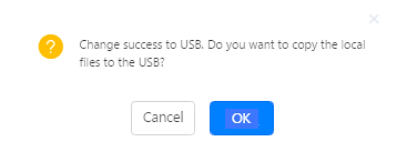
Once “USB Disk” or “SD Card” is selected, click on “OK”. The user will be prompted to confirm to copy the local files to the external storage device.
Click on “OK” to continue. The users will be prompted a new dialog to select the categories for the files to be copied over.
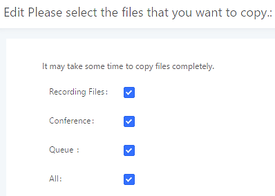
On the UCM6510, recording files are generated and exist in 3 categories: normal call recording files, conference recording files, and call queue recording files. Therefore, users have the following options when select the categories to copy the files to the external device:
- Recording Files: Copy the normal recording files to the external device.
- Conference: Copy the conference recording files to the external device.
- Queue: Copy the call queue recording files to the external device.
- All: Copy all recording files to the external device.
Provisioning
Overview
Grandstream SIP Devices can be configured via Web interface as well as via configuration file through TFTP/HTTP/HTTPS download. All Grandstream SIP devices support a proprietary binary format configuration file and XML format configuration file. The UCM6510 provides a Plug and Play mechanism to auto-provision the Grandstream SIP devices in a zero-configuration manner by generating XML config file and having the phone to download it within LAN area. This allows users to finish the installation with ease and properly manage SIP devices.
To provision a phone, three steps are involved, i.e., discovery, configuration and provisioning. This section explains how Zero Config works on the UCM6510. The settings for this feature can be accessed via Web GUI🡪Value-added Features🡪Zero Config.
Configuration Architecture for End Point Device
The end point device configuration in Zero Config is divided into the following three layers with priority from the lowest to the highest:
- Global
This is the lowest layer. Users can configure the most basic options that could apply to all Grandstream SIP devices during provisioning via Zero Config.
- Model
In this layer, users can define model-specific options for the configuration template.
- Device
This is the highest layer. Users can configure device-specific options for the configuration for individual device here.
Each layer also has its own structure in different levels. Please see figure below. The details for each layer are explained in sections [Global Configuration], [Model Configuration] and [Device Configuration].
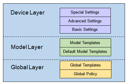
The configuration in model layer and device layer have all the options in global layers already, i.e., the options in global layer is a subset of the options in model layer and device layer. If an option is set in all three layers with different values, the highest layer value will override the value in lower layer. For example, if the user selects English for Language setting in Global Policy and Spanish for Language setting in Default Model Template, the language setting on the device to be provisioned will use Spanish as model layer has higher priority than global layer. To sum up, configurations in higher layer will always override the configurations for the same options/fields in the lower layer when presented at the same time.
After understanding the Zero Config configuration architecture, users could configure the available options for end point devices to be provisioned by the UCM6510 by going through the three layers. This configuration architecture allows users to set up and manage the Grandstream end point devices in the same LAN area in a centralized way.
Auto Provisioning Settings
By default, the Zero Config feature is enabled on the UCM6510 for auto provisioning. Two methods of auto provisioning are used.
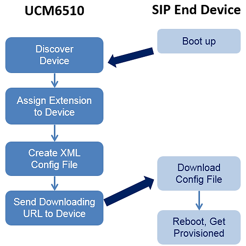
- SIP SUBSCRIBE
When the phone boots up, it sends out SUBSCRIBE to a multicast IP address in the LAN. The UCM6510 discovers it and then sends a NOTIFY with the XML config file URL in the message body. The phone will then use the path to download the config file generated in the UCM6510 and take the new configuration.
- DHCP OPTION 66
This method should be used only when the UCM6510 is set to “Route” mode under Web GUI🡪System Settings🡪Network Settings🡪Basic Settings: Method. When the phone restarts (by default DHCP Option 66 is turned on), it will send out a DHCP DISCOVER request. The UCM6510 receives it and returns DHCP OFFER with the config server path URL in the Option 66, for example, https://192.168.2.1:8089/zccgi/. The phone will then use the path to download the config file generated in the UCM6510.
To start the auto provisioning process, under Web GUI🡪Value-added Features🡪Zero Config🡪Zero Config Settings, fill in the auto provision information.
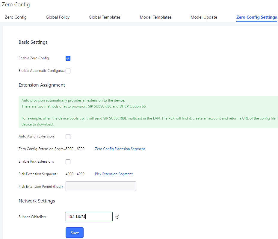
|
Enable Zero Config |
Enable or disable the Zero Config feature on the PBX. The default setting is enabled. |
|
Enable Automatic Configuration Assignment |
By default, this is disabled. If disabled, when SIP device boots up, the UCM6510 will only send the configuration path to the device when you have any manual configuration on the device. This manual configuration includes:
Note: When disabled, SIP devices can still be provisioned by manually sending NOTIFY from the UCM6510 which will include the XML config file URL for the SIP device to download. |
|
Auto Assign Extension |
If enabled, when the device is discovered, the PBX will automatically assign an extension within the range defined in “Zero Config Extension Segment” to the device. The default setting is disabled. |
|
Zero Config Extension Segment |
Click on the link “Zero Config Extension Segment” to specify the extension range to be assigned if “Automatically Assign Extension” is enabled. The default range is 5000-6299. Zero Config Extension Segment range can be defined in Web GUI🡪PBX Settings🡪General Settings page🡪Extension Preference section: “Auto Provision Extensions”. |
|
Enable Pick Extension |
If enabled, the extension list will be sent out to the device after receiving the device’s request. This feature is for the GXP series phones that support selecting extension to be provisioned via phone’s LCD. The default setting is disabled. |
|
Pick Extension Segment |
Click on the link “Pick Extension Segment” to specify the extension list to be sent to the device. The default range is 4000 to 4999. Pick Extension Segment range can be defined in Web GUI🡪PBX Settings🡪General Settings🡪General page🡪Extension Preference section: “Pick Extensions”. |
|
Pick Extension Period (hour) |
Specify the number of minutes to allow the phones being provisioned to pick extensions. |
|
This feature allows the UCM to provision devices in different subnets other than UCM network. Enter subnets IP addresses to allow devices within these subnets to be provisioned. The syntax is <IP>/<CIDR>. Examples: 10.0.0.1/8 192.168.6.0/24 Note: Only private IP ranges (10.0.0.0 | 172.16.0.0 | 192.168.0.0) are supported. |
Please make sure an extension is manually assigned to the phone or “Automatically Assign Extension” is enabled during provisioning. After the configuration on the UCM6510 Web GUI, click on “Save” and “Apply Changes”. Once the phone boots up and picks up the config file from the UCM6510it will immediately apply the configuration.
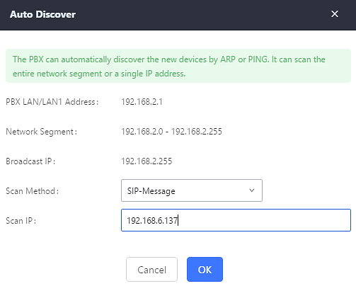
Discovery
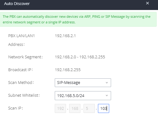
Grandstream endpoints are automatically discovered after bootup. Users could also manually discover device by specifying the IP address or scanning the entire LAN network. Three methods are supported to scan the devices.
- PING
- ARP
- SIP Message (NOTIFY)
Click on “Auto Discover” under Web GUI🡪Value-added Features🡪Zero Config🡪Zero Config, fill in the “Scan Method” and “Scan IP”. The IP address segment will be automatically filled in based on the network mask detected on the UCM6510. If users need scan the entire network segment, enter 255 (for example, 192.168.5.255) instead of a specific IP address. Then click on “Save” to start discovering the devices within the same network. To successfully discover the devices, “Zero Config” needs to be enabled on the UCM6510 Web GUI🡪Value-added Features🡪Zero Config🡪Auto Provisioning Settings.
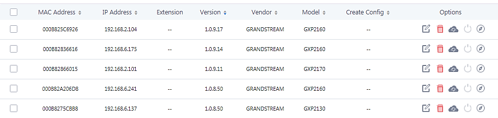
The following figure shows a list of discovered phones. The MAC address, IP Address, Extension (if assigned), Version, Vendor, Model, Connection Status, Create Config, Options Edit /Delete /Update /Reboot /Access Device WebGUI) are displayed in the list.
Auto Discover can also search for devices located on other subnets, in condition for the subnet to be added under Zero Config Settings 🡪 Subnet Whitelist. The method allowed to auto discover other subnets then the UCM’s is SIP-Message like shown below.
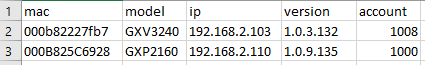
Uploading Devices List
Besides the built-in discovery method on the UCM, users could prepare a list of devices on .CSV file and upload it by clicking on the button ![]() , after which a success message prompt should be displayed.
, after which a success message prompt should be displayed.
Users need to make sure that the CSV file respects the format as shown on the following figure and that the entered information is correct (valid IP address, valid MAC address, device model, version, account..etc.), otherwise the UCM will reject the file and the operation will fail:
Managing discovered devices
- Sorting: Press or to sort per MAC Address, IP Address, Version, Vendor, Model or Create Config columns from lower to higher or higher to lower respectively.
- Filter: Select a filter
 to display corresponding results.
 - All: Display all discovered devices.
- Scan Results: Display only manually discovered devices. [Discovery]
- IP Address: Enter device IP and press Search button.
- MAC Address: Enter device MAC and press Search button.
- Model: Enter a model name and press Search button. Example: GXP2130.
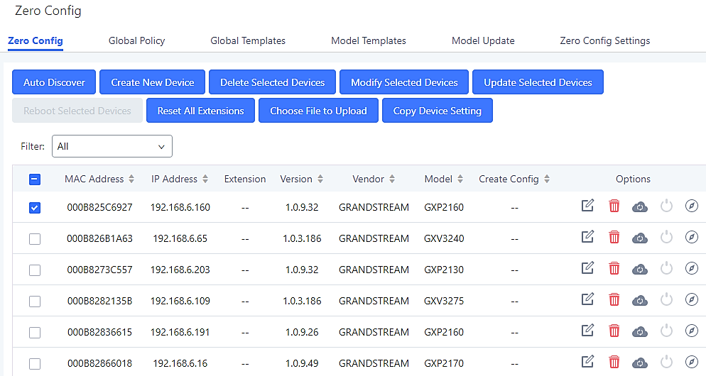
From the main menu of zero config, users can perform the following operations:
- Click on
 in order to access to the discovery menu as shown on [Discovery] section.
 - Click on
 to add a new device to zero config database using its MAC address.
 - Click on
 to delete selected devices from the zero-config database.
 - Click on
 to modify selected devices.
 - Click on
 to batch update a list of devices, the UCM on this case will send SIP NOTIFY message to all selected devices to update them at once.
 - Click on
 to reboot selected devices (the selected devices, should have been provisioned with extensions since the phone will authenticate the server which is trying to send it reboot command).
 - Click on
 to clear all devices configurations.
 - Click on
 to upload CSV file containing list of devices.
 - Click on
 to copy configuration from one device to another. This can be useful for easily replace devices and note that this feature works only between devices of same model.
All these operations will be detailed on the next sections.
Global Configuration
Global Policy
Global configuration will apply to all the connected Grandstream SIP end point devices in the same LAN with the UCM6510 no matter what the Grandstream device model it is. It is divided into two levels:
- Web GUI🡪Value-added Features🡪Zero Config🡪Global Policy
- Web GUI🡪Value-added Features🡪Zero Config🡪Global Templates.
- Global Templates configuration has higher priority to Global Policy configuration.
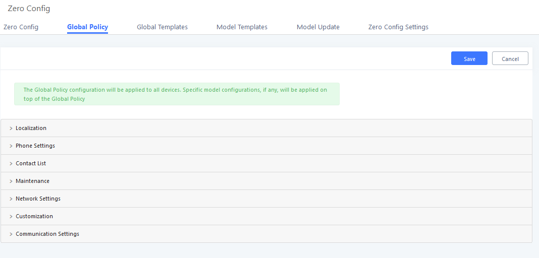
Global Policy can be accessed in Web GUI🡪Value-added Features🡪Zero Config🡪Global Policy page. On the top of the configuration table, users can select category in the “Options” dropdown list to quickly navigate to the category. The categories are:
- Localization: configure display language, data and time.
- Phone Settings: configure dial plan, call features, NAT, call progress tones and etc.
- Contact List: configure LDAP and XML phonebook download.
- Maintenance: configure upgrading, web access, Telnet/SSH access and syslog.
- Network Settings: configure IP address, QoS and STUN settings.
- Customization: customize LCD screen wallpaper for the supported models.
- Communication Settings: configure Email and FTP settings
Select the checkbox on the left of the parameter you would like to configure to activate the dropdown list for this parameter.
The following tables list the Global Policy configuration parameters for the SIP end device.
|
Language settings | |
|
Language |
Select the LCD display language on the SIP end device. |
|
Date and Time | |
|
Date Format |
Configure the date display format on the SIP end device’s LCD. |
|
Time Format |
Configure the time display in 12-hour or 24-hour format on the SIP end device’s LCD. |
|
NTP Server |
Configure the URL or IP address of the NTP server. The SIP end device may obtain the date and time from the server. |
|
Time Zone |
Configure the time zone used on the SIP end device. |
|
Default Call Settings | |
|
Dial Plan |
Configure the default dial plan rule. For syntax and examples, please refer to user manual of the SIP devices to be provisioned for more details. |
|
Enable Call Features |
When enabled, “Do Not Disturb”, “Call Forward” and other call features can be used via the local feature code on the phone. Otherwise, the ITSP feature code will be used. |
|
Use # as Dial Key |
If set to “Yes”, pressing the number key “#” will immediately dial out the input digits. |
|
Auto Answer by Call-info |
If set to “Yes”, the phone will automatically turn on the speaker phone to answer incoming calls after a short reminding beep, based on the SIP Call-Info header sent from the server/proxy. The default setting is enabled. |
|
NAT Traversal |
Configure if NAT traversal mechanism is activated. |
|
User Random Port |
If set to “Yes”, this parameter will force random generation of both the local SIP and RTP ports. |
|
General Settings | |
|
Call Progress Tones |
Configure call progress tones including ring tone, dial tone, second dial tone, message waiting tone, ring back tone, call waiting tone, busy tone and reorder tone using the following syntax: f1=val, [f2=val,] c=on1/ off1[- on2/ off2[- on3/ off3]];
|
|
HEADSET Key Mode |
Select “Default Mode” or “Toggle Headset/Speaker” for the Headset key. Please refer to user manual of the SIP devices to be provisioned for more details. |
|
LDAP Phonebook | |
|
Source |
Select “Manual” or “PBX” as the LDAP configuration source.
|
|
Address |
Configure the IP address or DNS name of the LDAP server. |
|
Port |
Configure the LDAP server port. The default value is 389. |
|
Base DN |
This is the location in the directory where the search is requested to begin. Example:
|
|
Username |
Configure the bind “Username” for querying LDAP servers. The field can be left blank if the LDAP server allows anonymous binds. |
|
Password |
Configure the bind “Password” for querying LDAP servers. The field can be left blank if the LDAP server allows anonymous binds. |
|
Number Filter |
Configure the filter used for number lookups. Please refer to user manual for more details. |
|
Name Filter |
Configure the filter used for name lookups. Please refer to user manual for more details. |
|
Version |
Select the protocol version for the phone to send the bind requests. The default value is 3. |
|
Name Attribute |
Specify the “name” attributes of each record which are returned in the LDAP search result. Example:
|
|
Number Attribute |
Specify the “number” attributes of each record which are returned in the LDAP search result. Example:
|
|
Display Name |
Configure the entry information to be shown on phone’s LCD. Up to 3 fields can be displayed. Example:
|
|
Max Hits |
Specify the maximum number of results to be returned by the LDAP server. Valid range is 1 to 3000. The default value is 50. |
|
Search Timeout |
Specify the interval (in seconds) for the server to process the request and client waits for server to return. Valid range is 0 to 180. Default value is 30. |
|
Sort Results |
Specify whether the searching result is sorted or not. Default setting is No. |
|
Incoming Calls |
Configure to enable LDAP number searching when receiving calls. The default setting is No. |
|
Outgoing Calls |
Configure to enable LDAP number searching when making calls. The default setting is No. |
|
Lookup Display Name |
Configures the display name when LDAP looks up the name for incoming call or outgoing call. It must be a subset of the LDAP Name Attributes. |
|
XML Phonebook | |
|
Phonebook XML Server |
Select the source of the phonebook XML server.
Disable phonebook XML downloading.
Once selected, users need specify downloading protocol HTTP, HTTPS or TFTP and the server path to download the phonebook XML file. The server path could be IP address or URL, with up to 256 characters.
Once selected, click on the Server Path field to upload the phonebook XML file. Please note after uploading the phonebook XML file to the server, the original file name will be used as the directory name and the file will be renamed as phonebook.xml under that directory. |
|
Phonebook Download Interval |
Configure the phonebook download interval (in Minute). If set to 0, automatic download will be disabled. Valid range is 5 to 720. |
|
Remove manually edited entries on download |
If set to “Yes”, when XML phonebook is downloaded, manually added entries will be removed. |
|
Upgrade and Provision | |
|
Firmware Source |
UCM can provision the firmware source to devices. The following options are available:
If selected, complete the configuration for the following four parameters: “Upgrade Via”, “Server Path”, “File Prefix” and “File Postfix”.
Firmware can be uploaded to the UCM6510 internal storage for firmware upgrade. If selected, click on “Manage Storage” icon next to “Directory” option, upload firmware file and select directory for the end device to retrieve the firmware file.
If selected, the USB storage device needs to be plugged into the UCM6510 and the firmware file must be put under a folder named “ZC_firmware” in the USB storage root directory.
If selected, an SD card needs to be plugged into the UCM6510 and the firmware file must be put under a folder named “ZC_firmware” in the USB storage root directory. |
|
Upgrade via |
When URL is selected as firmware source, configure upgrade via TFTP, HTTP or HTTPS. |
|
Server Path |
When URL is selected as firmware source, configure the firmware upgrading server path. |
|
File Prefix |
When URL is selected as firmware source, configure the firmware file prefix. If configured, only the firmware with the matching encrypted prefix will be downloaded and flashed into the phone, if URL is selected as firmware source. |
|
File Postfix |
When URL is selected as firmware source, configure the firmware file postfix. If configured, only the configuration file with the matching encrypted postfix will be downloaded and flashed into the phone. |
|
Allow DHCP Option 43/66 |
If DHCP option 43 or 66 is enabled on the LAN side, the TFTP server can be redirected. |
|
Automatic Upgrade |
If enabled, the end point device will automatically upgrade if a new firmware is detected. Users can select automatic upgrading by day, by week or by minute.
Once selected, specify the day of the week to check HTTP/TFTP server for firmware upgrades or configuration files changes.
Once selected, specify the hour of the day to check the HTTP/TFTP server for firmware upgrades or configuration files changes.
Once selected, specify the interval X that the SIP end device will request for new firmware every X minutes. |
|
Firmware Upgrade Rule |
Specifies how firmware upgrade and provision requests will be sent. |
|
Web Access | |
|
Admin Password |
Configure the administrator password for admin level login. |
|
End-User Password |
Configure the end-user password for the end user level login. |
|
Web Access Mode |
Select HTTP or HTTPS as the web access protocol. |
|
Web Server Port |
Configure the port for web access. The valid range is 1 to 65535. |
|
Security | |
|
Disable Telnet/SSH |
Enable Telnet/SSH access for the SIP end device. If the SIP end device supports Telnet access, this option controls the Telnet access of the device; if the SIP end device supports SSH access, this option controls the SSH access of the device. |
|
Syslog | |
|
Syslog Server |
Configure the URL/IP address for the syslog server. |
|
Syslog Level |
Select the level of logging for syslog. |
|
Send SIP Log |
Configures whether SIP messages will be included in the syslog. |
|
Basic Settings | |
|
IP Address |
Configures how the SIP endpoint will obtain IP addresses. The following options are available:
Once selected, users can specify the Host Name (option 12) of the SIP end device as DHCP client, and Vendor Playlist ID (option 60) used by the client and server to exchange vendor playlist ID information.
Once selected, users need specify the Account ID, Password and Service Name for PPPoE. |
|
Advanced Setting | |
|
Layer 3 QoS |
Define the Layer 3 QoS parameter. This value is used for IP Precedence, Diff-Serv or MPLS. Valid range is 0-63. |
|
Layer 2 QoS Tag |
Assign the VLAN Tag of the Layer 2 QoS packets. Valid range is 0 -4095. |
|
Layer 2 QoS Priority Value |
Assign the priority value of the Layer 2 QoS packets. Valid range is 0-7. |
|
STUN Server |
Configure the IP address or Domain name of the STUN server. Only non-symmetric NAT routers work with STUN. |
|
Keep Alive Interval |
Specify how often the phone will send a blank UDP packet to the SIP server to keep the “ping hole” on the NAT router to open. Valid range is 10-160. |
|
Wallpaper | |
|
Screen Resolution 1024 x 600 |
Check this option if the SIP endpoint uses a 1024×600 resolution wallpaper.
Configure the location where wallpapers are stored.
If “URL” is selected as source, specify the URL of the wallpaper file. If “Local UCM Server” is selected as source, click to upload wallpaper file to the UCM6510. |
|
Screen Resolution 800 x 400 |
Check this option if the SIP endpoint uses a 800×400 resolution wallpaper.
Configure the location where wallpapers are stored.
If “URL” is selected as source, specify the URL of the wallpaper file. If “Local UCM Server” is selected as source, click to upload wallpaper file to the UCM6510. |
|
Screen Resolution 480 x 272 |
Check this option if the SIP endpoint uses a 320×240 resolution wallpaper.
Configure the location where wallpapers are stored.
If “URL” is selected as source, specify the URL of the wallpaper file. If “Local UCM Server” is selected as source, click to upload wallpaper file to the UCM6510. |
|
Screen Resolution 320 x 240 |
Check this option if the SIP endpoint uses a 320×240 resolution wallpaper.
Configure the location where wallpapers are stored.
If “URL” is selected as source, specify the URL of the wallpaper file. If “Local UCM Server” is selected as source, click to upload wallpaper file to the UCM6510. |
|
Email Settings | |
|
SMTP Settings | Check this option to configure the email settings that will be sent to the provisioned phones:
IP address of the SMTP server
SMTP server port
Email address
Username of the sender
Email where recovered password will be sent
Email address where alarms notifications will be sent
Email address where alarms notifications will be sent
Enable SSL protocol for SMTP |
|
FTP | |
|
FTP |
Check this option to configure the FTP settings that will be sent to the provisioned phones:
Either FTP or Central Storage
FTP server address
FTP port to be used
FTP username
FTP Directory path |
Global Templates
Global Templates can be accessed in Web GUI🡪Value-added Features🡪Zero Config🡪Global Templates. Users can create multiple global templates with different sets of configurations and save the templates. Later on, when the user configures the device in Edit Device dialog🡪Advanced Settings, the user can select to use one of the global templates for the device. Please refer to section [Manage Devices] for more details on using the global templates.
When creating global template, users can select the categories and the parameters under each category to be used in the template. The global policy and the selected global template will both take effect when generating the config file. However, the selected global template has higher priority to the global policy when it comes to the same setting option/field. If the same option/field has different value configured in the global policy and the selected global template, the value for this option/field in the selected global template will override the value in global policy.
- Click on “Create New Template” to add a global template. Users will see the following configurations.
|
Template Name |
Create a name to identify this global template. |
|
Description |
Provide a description for the global template. This is optional. |
|
Active |
Check this option to enable the global template. |
- Click on to edit the global template.
The window for editing global template is shown in the following figure. In the “Options” field, after entering the option name key word, the options containing the key word will be listed. Users could then select the options to be modified and click on “Add Option” to add it into the global template.
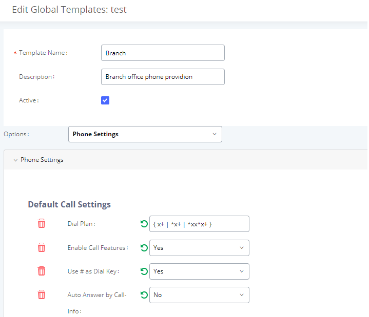
The added options will show in the list. Users can then enter or select value for each option to be used in the global template. On the left side of each added option, users can click on ![]() to remove this option from the template. On the right side of each option, users can click on
to remove this option from the template. On the right side of each option, users can click on ![]() to reset the option value to the default value.
to reset the option value to the default value.
- Click on “Save” to save this global template.
- The created global templates will show in the Web GUI🡪Value-added Features🡪Zero Config🡪Global Templates page. Users can click on to delete the global template or click on “Delete Selected Templates” to delete multiple selected templates at once.
- Click on “Toggle Selected Template(s)” to toggle the status between enabled/disabled for the selected templates.
Model Configuration
Model Templates
Model layer configuration allows users to apply model-specific configurations to different devices. Users could create/edit/delete a model template by accessing Web GUI, page Value-added Features🡪Zero Config🡪Model Templates. If multiple model templates are created and enabled, when the user configures the device in Edit Device dialog🡪Advanced Settings, the user can select to use one of the model templates for the device. Please refer to section [Manage Devices] for more details on using the model template.
For each created model template, users can assign it as default model template. If assigned as default model template, the values in this model template will be applied to all the devices of this model. There is always only one default model template that can be assigned at one time on the UCM6510.
The selected model template and the default model template will both take effect when generating the config file for the device. However, the model template has higher priority to default model template when it comes to the same setting option/field. If the same option/field has different value configured in the default model template and the selected model template, the value for this option/field in the selected model template will override the value in default model template.
- Click on “Create New Template” to add a model template.
|
Model |
Select a model to apply this template. The supported Grandstream models are listed in the dropdown list for selection. |
|
Template Name |
Create a name for the model template. |
|
Description |
Enter a description for the model template. This is optional. |
|
Default Model Template |
Select to assign this model template as the default model template. The value of the option in default model template will be overwritten if other selected model template has a different value for the same option. |
|
Active |
Check this option to enable the model template. |
- Click on to edit the model template.
The editing window for model template is shown in the following figure. In the “Options” field, enter the option name key word, the option that contains the key word will be listed. User could then select the option and click on “Add Option” to add it into the model template.
Once added, the option will be shown in the list below. On the left side of each option, users can click on ![]() to remove this option from the model template. On the right side of each option, users can click on
to remove this option from the model template. On the right side of each option, users can click on ![]() to reset the option to the default value.
to reset the option to the default value.
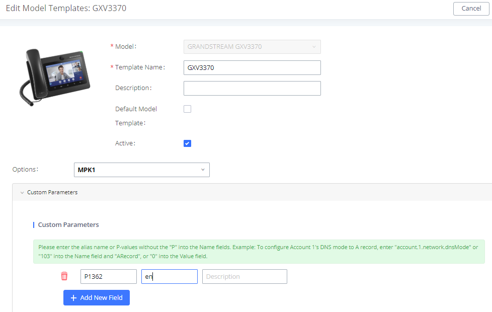
User could also click on “Add New Field” to add a P value number and the value to the configuration. The following figure shows setting P value “P1362” to “en”, which means the display language on the LCD is set to English. For P value information of different models, please refer to configuration template here https://content.grandstream.com/hubfs/Grandstream_Feb_2021/Zip%20File/config-template.zip
- Click on Save when done. The model template will be displayed on Web GUI🡪Value-added Features🡪Zero Config🡪Model Templates page.
- Click on to delete the model template or click on “Delete Selected Templates” to delete multiple selected templates at once.
- Click on “Toggle Selected Template(s)” to toggle the status between enabled/disabled for the selected model templates.
Model Update
UCM6510 zero config feature supports provisioning all models of Grandstream SIP end devices including OEM device models.
OEM Models
Users can associate OEM device models with their original Grandstream-branded models, allowing these OEM devices to be provisioned appropriately.
- Click on
 button.
 - In the Source Model field, select the Grandstream device that the OEM model is based on from the dropdown list.
- For the Destination Model and Destination Vendor field, enter the custom OEM model name and vendor name.
- The newly added OEM model should now be selectable as an option in Model fields.
Model Template Package List
Templates for most of the Grandstream models are built in with the UCM6510 already. Templates for GS Wave and Grandstream surveillance products require users to download and install under Web GUI🡪Value-added Features🡪Zero Config🡪Model Update first before they are available in the UCM6510 for selection. After downloading and installing the model template to the UCM6510, it will show in the dropdown list for “Model” selection when editing the model template.
- Click on
 to download the template.
 - Click on
 to upgrade the model template. Users will see this icon available if the device model has template updated in the UCM6510.
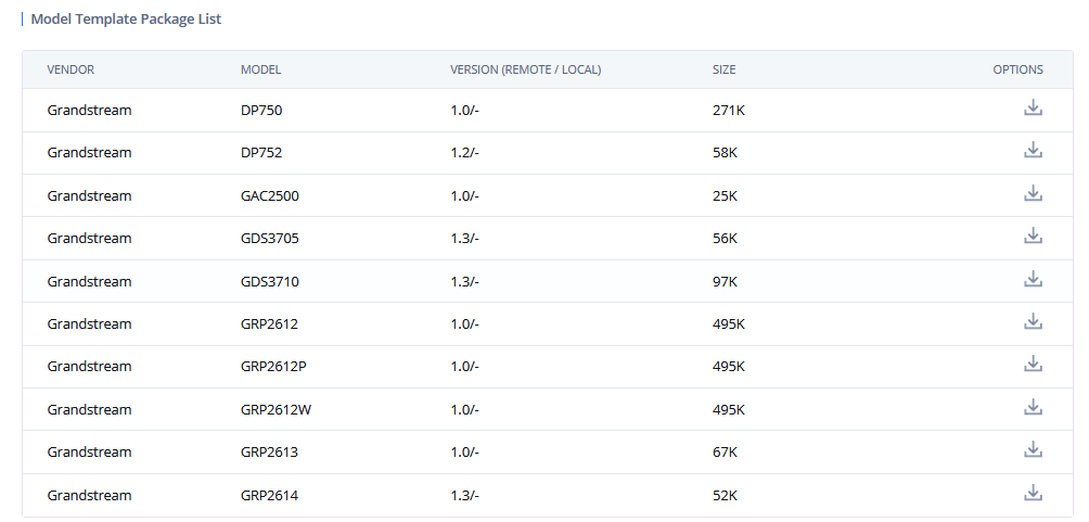
Upload Model Template Package
In case the UCM6510 is placed in the private network and Internet access is restricted, users will not be able to get packages by downloading and installing from the remote server. Model template packages can be manually uploaded to the UCM. Please contact Grandstream customer support if the model package is needed for manual uploading.
Device Configuration
On Web GUI, page Value-added Features🡪Zero Config🡪Zero Config, users could create new device, delete existing device(s), make special configuration for a single device, or send NOTIFY to existing device(s).
Create New Device
Besides configuring the device after the device is discovered, users could also directly create a new device and configure basic settings before the device is discovered by the UCM6510. Once the device is plugged in, it can then be discovered and provisioned. This gives the system administrator adequate time to set up each device beforehand.
Click on “Create New Device” and the following dialog will show. Follow the steps below to create the configurations for the new device.
- Firstly, select a model for the device to be created and enter its MAC address, IP address and firmware version (optional) in the corresponding field.
- Basic settings will show a list of settings based on the model selected in step 1. Users could assign extensions to accounts, assign functions to Line Keys and Multiple-Purposed Keys if supported on the selected model.
- Click on “Create New Device” to save the configuration for this device.
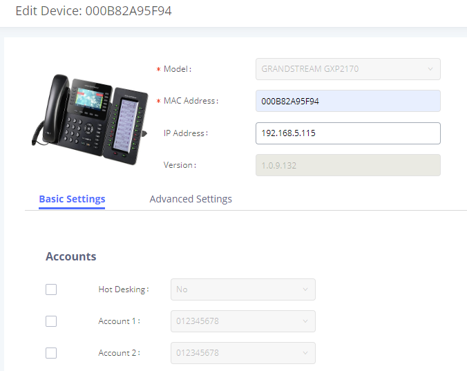
Manage Devices
The device manually created or discovered from Auto Discover will be listed in the Web GUI🡪Value-added Features🡪Zero Config🡪Zero Config page. Users can see the devices with their MAC address, IP address, vendor, model etc.

- Click on to access the Web GUI of the phone.
- Click on to edit the device configuration.
A new dialog will be displayed for the users to configure “Basic” settings and “Advanced” settings. “Basic” settings have the same configurations as displayed when manually creating a new device, i.e., account, line key and MPK settings; “Advanced” settings allow users to configure more details in a five-level structure.
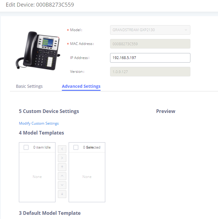
A preview of the “Advanced” settings is shown in the above figure. There are five levels configurations as described in (1) (2) (3) (4) (5) below, with priority from the lowest to the highest. The configurations in all levels will take effect for the device. If there are same options existing in different level configurations with different value configured, the higher-level configuration will override the lower level configuration.
- Global Policy
This is the lowest level configuration. The global policy configured in Web GUI🡪Value-added Features🡪Zero Config🡪Global Policy will be applied here. Clicking on “Modify Global Policy” to redirect to page Value-added Features🡪Zero Config🡪Global Policy.
- Global Templates
Select a global template to be used for the device and click on ![]() to add. Multiple global templates can be selected, and users can arrange the priority by adjusting orders via
to add. Multiple global templates can be selected, and users can arrange the priority by adjusting orders via ![]() and
and ![]() . All the selected global templates will take effect. If the same option exists on multiple selected global templates, the value in the template with higher priority will override the one in the template with lower priority. Click on
. All the selected global templates will take effect. If the same option exists on multiple selected global templates, the value in the template with higher priority will override the one in the template with lower priority. Click on ![]() to remove the global template from the selected list.
to remove the global template from the selected list.
- Default Model Template
Default Model Template will be applied to the devices of this model. Default model template can be configured in model template under Web GUI🡪Value-added Features🡪Zero Config🡪Model Templates page. Please see default model template option in [Table 30: Create New Model Template].
- Model Templates
Select a model template to be used for the device and click on ![]() to add. Multiple global templates can be selected, and users can arrange the priority by adjusting orders via
to add. Multiple global templates can be selected, and users can arrange the priority by adjusting orders via ![]() and
and ![]() . All the selected model templates will take effect. If the same option exists on multiple selected model templates, the value in the template with higher priority will override the one in the template with lower priority. Click on
. All the selected model templates will take effect. If the same option exists on multiple selected model templates, the value in the template with higher priority will override the one in the template with lower priority. Click on ![]() to remove the model template from the selected list.
to remove the model template from the selected list.
- Customize Device Settings
This is the highest-level configuration in the “Advanced” settings of the device. Click on “Modify Customize Device Settings” and following dialog will show.
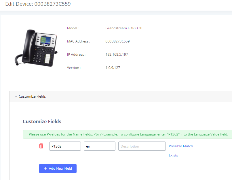
Scroll down in the dialog to view and edit the device-specific options. If the users would like to add more options which are not in the pre-defined list, click on “Add New Field” to add a P value number and the value to the configuration. The following figure shows setting P value “P1362” to “en”, which means the display language on the LCD is set to English.
The warning information next to the P value field indicates that the option matching the P value number exists in the configuration already.
For P value information of different models, please refer to configuration template here:
http://www.grandstream.com/sites/default/files/Resources/config-template.zip.

- Select multiple devices that need to be modified and then click on
 to batch modify devices.
If selected devices are of the same model, the configuration dialog is like the following figure. Configurations in five levels are all available for users to modify.
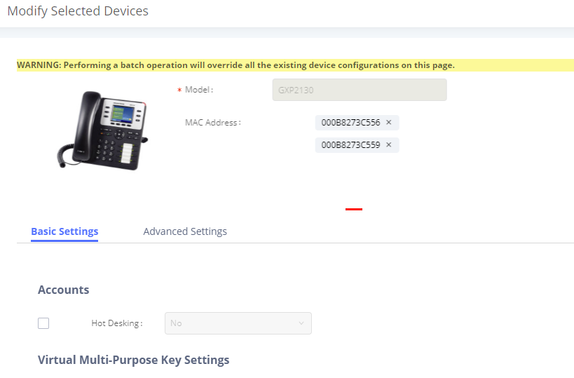
If selected devices are of different models, the configuration dialog is like the following figure. Click on ![]() to view more devices of other models. Users are only allowed to make modifications in Global Templates and Global Policy level.
to view more devices of other models. Users are only allowed to make modifications in Global Templates and Global Policy level.
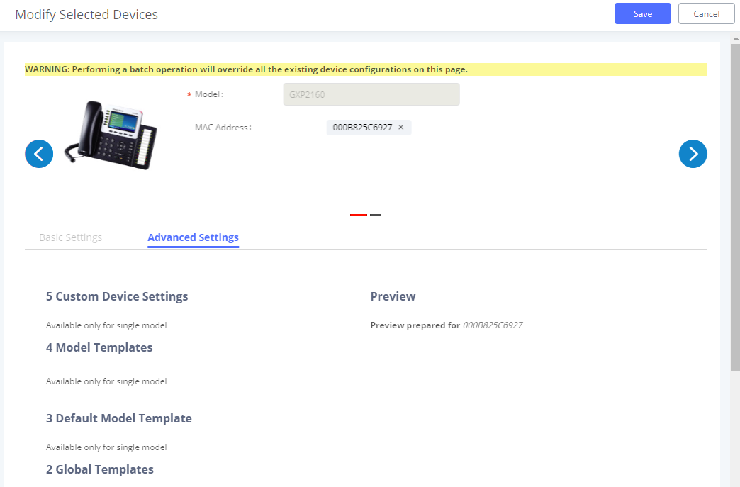
After the above configurations, save the changes and go back to Web GUI🡪Value-added Features🡪Zero Config🡪Zero Config page. Users could then click on ![]() to send NOTIFY to the SIP end point device and trigger the provisioning process. The device will start downloading the generated configuration file from the URL contained in the NOTIFY message.
to send NOTIFY to the SIP end point device and trigger the provisioning process. The device will start downloading the generated configuration file from the URL contained in the NOTIFY message.
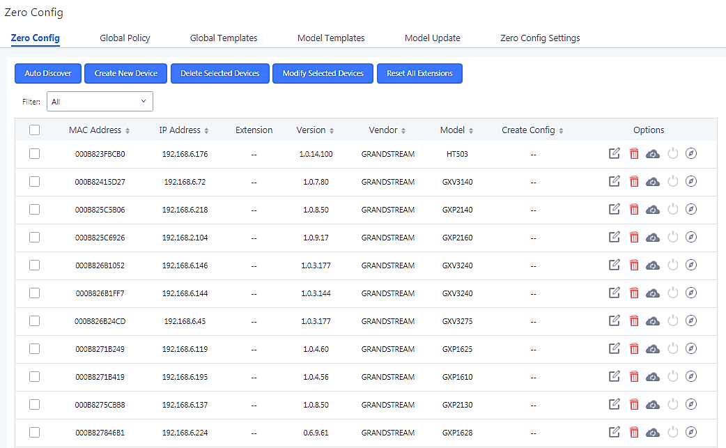
In this web page, users can also click on “Reset All Extensions” to reset the extensions of all the devices.
Example Application
Assuming in a small business office where there are 8 GXP2140 phones used by customer support and 1 GXV3275 phone used by customer support supervisor. 3 of the 8 customer support members speak Spanish and the rest speak English. We could deploy the following configurations to provisioning the office phones for the customer support team.
- Go to Web GUI🡪Value-added Features🡪Zero Config🡪Auto Provision Settings, select “Enable Zero Config”.
- Go to Web GUI🡪Value-added Features🡪Zero Config🡪Global Policy, configure Date Format, Time Format and Firmware Source as follows.
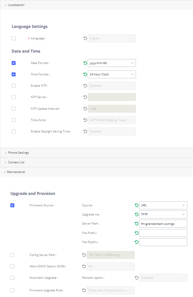
- Go to Web GUI🡪Value-added Features🡪Zero Config🡪Model Templates, create a new model template “English Support Template” for GXP2140. Add option “Language” and set it to “English”. Then select the option “Default Model Template” to make it the default model template.
- Go to Web GUI🡪Value-added Features🡪Zero Config🡪Model Templates, create another model template “Spanish Support Template” for GXP2140. Add option “Language” and set it to “Español”.
- After 9 devices are powered up and connected to the LAN network, use “Auto Discover” function or “Create New Device” function to add the devices to the device list on Web GUI🡪Value-added Features🡪Zero Config🡪Zero Config.
- On Web GUI🡪Value-added Features🡪Zero Config🡪Zero Config page, users could identify the devices by their MAC addresses or IP addresses displayed on the list. Click on to edit the device settings.
- For each of the 5 phones used by English speaking customer support, in “Basic” settings select an available extension for account 1 and click on “Save”. Then click on “Advanced” settings tab to bring up the following dialog. Users will see the English support template is applied since this is the default model template. A preview of the device settings will be listed on the right side.
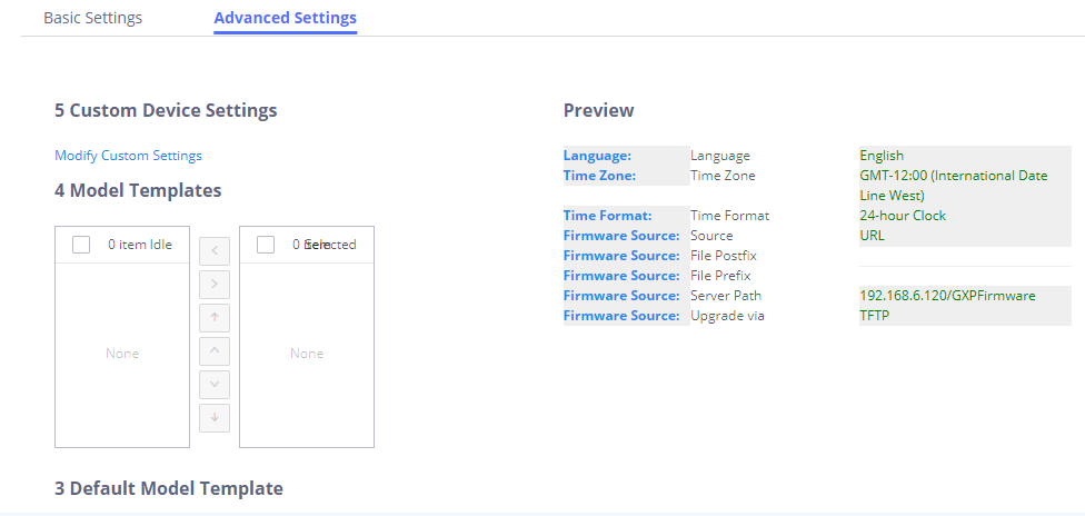
- For the 3 phones used by Spanish support, in “Basic” settings select an available extension for account 1 and click on “Save”. Then click on “Advanced” settings tab to bring up the following dialog.
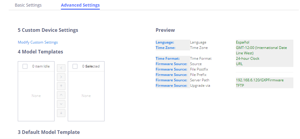
Select “Spanish Support Template” in “Model Template”. The preview of the device settings is displayed on the right side and we can see the language is set to “Español” since Model Template has the higher priority for the option “Language”, which overrides the value configured in default model template.
- For the GXV3370 used by the customer support supervisor, select an available extension for account 1 on “Basic” settings and click on “Save”. Users can see the preview of the device configuration in “Advanced” settings. There is no model template configured for GXV3370.
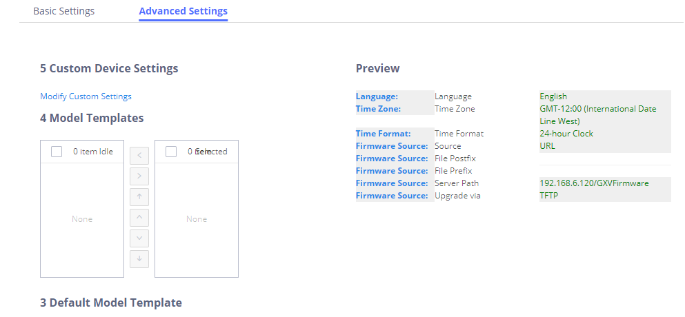
- Click on “Apply Changes” to apply saved changes.
- On the Web GUI🡪Value-added Features🡪Zero Config🡪Zero Config page, click on
 to send NOTIFY to trigger the device to download config file from UCM6510.
Now all the 9 phones in the network will be provisioned with a unique extension registered on the UCM6510. 3 of the phones will be provisioned to display Spanish on LCD and the other 5 will be provisioned to display English on LCD. The GXV3275 used by the supervisor will be provisioned to use the default language on LCD display since it is not specified in the global policy.
Extensions
Create New User
Create New SIP Extension
To create a new SIP extension, navigate to Extension/Trunk🡪Extensions and click on the Add button. The following window will appear:
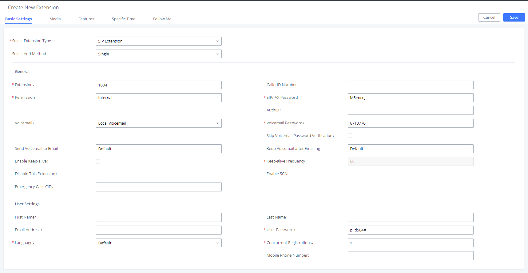
SIP extension options are divided into four categories:
- Basic Settings
- Media
- Features
- Specific Time
- Follow Me
Click on the tab to view or edit options belonging to that category. The configuration parameters are as follows.
General | |
Extension | The extension number associated with the user. Note: This filed supports (+) sign. |
CallerID Number | Configure the CallerID Number that would be applied for outbound calls from this user. Note: The ability to manipulate your outbound Caller ID may be limited by your VoIP provider. |
Permission | Assign permission level to the user. The available permissions are “Internal”, “Local”, “National” and “International” from the lowest level to the highest level. The default setting is “Internal”. Note: Users need to have the same level as or higher level than an outbound rule’s privilege to make outbound calls using this rule. |
SIP/IAX Password | Configure the password for the user. A random secure password will be automatically generated. It is recommended to use this password for security purpose. |
Auth ID | Configure the authentication ID for the user. If not configured, the extension number will be used for authentication. Note: This filed supports (+) sign. |
Voicemail | Configure Voicemail. There are three valid options and the default option is “Enable Local Voicemail”.
|
Voicemail Password | Configure the password to access the extension’s voicemail. A randomly generated password is used by default and is highly recommended for security. Only digits are supported. |
Skip Voicemail Password Verification | If enabled, users can skip password verification when dialing in via the My Voicemail feature code. This option is disabled by default. |
Send Voicemail Email Notification |
|
Send Voicemail to Email | If enabled, the voicemail will be attached to the email notification that is sent when a voicemail is received. Note: When set to “Default”, the global settings in Call Features🡪Voicemail🡪Voicemail Email Settings will be used. |
Keep Voicemail after Emailing | Configure whether or not to retain the voicemail in local storage after sending the voicemail attachment in the email notification. |
Enable Keep-alive | If enabled, empty SDP packet will be sent to the SIP server periodically to keep the NAT port open. |
Keep-alive Frequency | Configure the Keep-alive interval (in seconds) to check if the host is up. The default setting is 60 seconds. |
Disable This Extension | If selected, this extension will be disabled on the UCM6510. Note: The disabled extension still exists on the PBX but cannot be used on the end device. |
Emergency Calls CID | Caller ID number that will be used when calling out and receiving direct callbacks. |
User Settings | |
First Name | Configure the user’s first name. This field supports alphanumeric characters, underscores (_), and periods. |
Last Name | Configures the user’s last name. This field supports alphanumeric characters, underscores (_), and periods. |
Email Address | Configure the user’s email address. Email notifications will be sent to this address. |
User Password | Configure the password for user portal access. A random password is automatically generated by default and is highly recommended for security. |
Language | Select the voice prompt language that will be used for this extension. By default, the selected voice prompt language under PBX Settings🡪Voice Prompt🡪Language Settings will be used. To add more supported languages, please download the voice prompt language packages in the same page. |
Concurrent Registrations | The maximum allowed number of endpoint registrations to this extension. Default value is 1. |
Mobile Phone Number | Configure a phone number for the extension. Users can dial the Direct Dial Mobile Phone Prefix feature code (*88 by default) + extension number to directly dial this number. Example: Dial * |
Table 31: SIP Extension Configuration Parameters – Basic Settings
|
SIP Settings | |
|
NAT |
Use NAT when the UCM6510 is on a public IP communicating with devices hidden behind NAT (e.g., broadband router). If there is one-way audio issue, usually it is related to NAT configuration or Firewall’s support of SIP and RTP ports. The default setting is enabled. |
|
Enable Direct Media |
By default, the UCM6510 will route the media steams from SIP endpoints through itself. If enabled, the PBX will attempt to negotiate with the endpoints to route the media stream directly. It is not always possible for the UCM6510 to negotiate endpoint-to-endpoint media routing. The default setting is “No”. |
|
DTMF Mode |
Select DTMF mode for the user to send DTMF. The default setting is “RFC4733”. If “Info” is selected, SIP INFO message will be used. If “Inband” is selected, 64-kbit PCMU and PCMA are required. When “Auto” is selected, RFC4733 will be used if offered, otherwise “Inband” will be used. |
|
TEL URI |
If the phone has an assigned PSTN telephone number, this field should be set to “User=Phone”. “User=Phone” parameter will be attached to the Request-Line and “TO” header in the SIP request to indicate the E.164 number. If set to “Enable”, “Tel” will be used instead of “SIP” in the SIP request. |
|
Alert-Info |
Configure the Alert-Info, when UCM6510 receives an INVITE request, the Alert-Info header field specifies an alternative ring tone to the UAS. |
|
Enable T.38 UDPTL |
Enable or disable T.38 UDPTL support. |
|
SRTP |
Enable SRTP for the call. The default setting is disabled. |
|
Fax Mode |
Select Fax mode. The default setting is “None”.
|
| |
|
Access Control List manages the IP addresses that can register to this extension.
| |
|
Specifies allowed IP address or networks from where the extension can be registered. Up to 10 entries are allowed. Format: “xxx.xxx.xxx.xxx”, “xxx.xxx.xxx.xxx/32”, “[::]” or “[::]/128”. | |
| Select audio and video codec for the extension. The available codecs are: PCMU, PCMA, GSM, AAL2-G.726-32, G,726, G.722, G.729, G.723, OPUS, iLBC, ADPCM, H.264, H.263, H.263p and RTX. |
Call Transfer | |
Presence Status | Select which presence status to set for the extension and configure call forward conditions for each status. Six possible options are possible: “Available”, “Away”, “Chat”, “Custom”, “DND” and “Unavailable”. |
Call Forward Unconditional | Enable and configure the Call Forward Unconditional target number. Available options for target number are:
The default setting is “None”. |
CFU Time Condition | Select time condition for Call Forward Unconditional. CFU takes effect only during the selected time condition. The available time conditions are “Office Time”, “Out of Office Time”, “Holiday”, “Out of Holiday”, “Out of Office Time or Holiday” and “Specific”. Notes:
|
Call Forward No Answer | Configure the Call Forward No Answer target number. Available options for target number are:
|
CFN Time Condition | Select time condition for Call Forward No Answer. The available time conditions are “Office Time”, “Out of Office Time”, “Holiday”, “Out of Holiday”, “Out of Office Time or Holiday” and “Specific”. Notes:
|
Call Forward Busy | Configure the Call Forward Busy target number. Available options for target number are:
|
CFB Time Condition | Select time condition for Call Forward Busy. The available time conditions are “Office Time”, “Out of Office Time”, “Holiday”, “Out of Holiday”, “Out of Office Time or Holiday” and “Specific”. Notes:
|
Do Not Disturb | If enabled the extension will ignore all incoming calls |
DND Time Condition | Select time condition for Do Not Disturb. The available time conditions are “Office Time”, “Out of Office Time”, “Holiday”, “Out of Holiday”, “Out of Office Time or Holiday” and “Specific”. Notes:
|
DND Whitelist | If DND is enabled, all calls to this extension will be rejected except the numbers listed on this list. Note: The maximum number on the Whitelist is 10. |
FWD Whitelist | If call forward is enabled, all calls to this extension will be forwarded except the calls coming from the specified numbers on this list. Note: The Maximum number on the whitelist is 10. |
CC Settings | |
Enable CC | If enabled, UCM6510 will automatically alert this extension when a called party is available, given that a previous call to that party failed for some reason. By default, it is disabled. |
CC Mode | Two modes for Call Completion are supported:
The default setting is “Normal”. Note: The number of CC agents (for “Normal” mode) will now be limited by the extensions’ allowed number of concurrent registrations. |
CC Max Agents | Configure the maximum number of CCSS agents which may be allocated for this channel (when CC Mode is set to “For Trunk”). In other words, this number serves as the maximum number of CC requests this channel is allowed to make. Min. value is 1. |
CC Max Monitors | Configure the maximum number of monitor structures which may be created for this device (when CC Mode is set to “For Trunk”). This number tells how many callers may request CC services for a specific device at one time. The minimum value is 1. |
Ring Simultaneously | |
Ring Simultaneously | Enable this option to have an external number ring simultaneously along with the extension. If a register trunk is used for outbound, the register number will be used to be displayed for the external number as caller ID number. |
External Number | Set the external number to be rang simultaneously. ‘-’ is the connection character which will be ignored. This field accepts only letters, numbers, and special characters + = * #. |
Time Condition for Ring Simultaneously | Ring the external number simultaneously along with the extension based on this time condition. |
Use callee DOD on FWD or Ring Simultaneously | Use the DOD number when calls are being diverted/forwarded to external destinations or when ring simultaneous is configured. |
Monitor privilege control | |
Allow call-barging | Add members from “Available Extensions” to “Selected Extensions” so that the selected extensions can spy on the used extension using feature code. |
Seamless transfer privilege control | |
Allowed to seamless transfer | Any extensions on the UCM can perform seamless transfer. When using Pickup Incall feature, only extensions available on the “Selected Extensions” list can perform seamless transfer to the edited extension. |
Other Settings | |
Ring Timeout | Configure the number of seconds to ring the user before the call is forwarded to voicemail (voicemail is enabled) or hang up (voicemail is disabled). If not specified, the default ring timeout is 60 seconds on the UCM6510, which can be configured in the global ring timeout setting under Web GUI🡪PBX Settings🡪General Settings: General Preference. The valid range is between 5 seconds and 600 seconds. Note: If the end point also has a ring timeout configured, the actual ring timeout used is the shortest time set by either device. |
Auto Record | Enable automatic recording for the calls using this extension. The default setting is disabled. The recording files can be accessed under Web GUI🡪CDR🡪Recording Files. |
Skip Trunk Auth |
|
Time Condition for Skip Trunk Auth | If ‘Skip Trunk Auth’ is set to ‘By Time’, select a time condition during which users can skip entering password when making outbound calls. |
Dial Trunk Password | Configure personal password when making outbound calls via trunk. |
Support Hot-Desking Mode | If enabled, SIP Password will accept only alphabet characters and digits. Auth ID will be changed to the same as Extension. |
Enable LDAP | If enabled, the extension will be added to LDAP Phonebook PBX list. |
Enable WebRTC Support | Enable registration and call from Web RTC. |
Music On Hold | Specify which Music On Hold playlist to suggest to the bridged channel when putting them on hold. |
Enable Seamless Transfer | Enable the seamless transfer for this extension. |
Permission | Set the permission for this extension when using the seamless transfer |
Call Duration Limit | The maximum duration of call-blocking. |
Maximum Call Duration | The maximum call duration (in seconds). The default value 0 means no limit. |
Custom Call-info for Auto Answer | If enabled, when a call is sent to this extension from UCM, the SIP INVITE message will contain a Call-info header indicating auto answer. |
Enable Call Waiting | If disabled, UCM will not ring the extension if it is already in a call and will give the caller a busy response. |
Email Missed Calls | When enabled, the UCM sends a log of missed calls to the extension's email address. |
Table 33: SIP Extension Configuration Parameters – Features
|
Specific Time | |
|
Time Condition |
Click to add Time Condition to configure specific time for this extension. |
Create New IAX Extension
The UCM6510 supports Inter-Asterisk eXchange (IAX) protocol. IAX is used for transporting VoIP telephony sessions between servers and terminal devices. IAX is similar to SIP but also has its own characteristic. For more information, please refer to RFC5465.
To manually create new IAX user, go to Web GUI🡪Extension/Trunk🡪Extensions. Click on “Add” and a new dialog window will show for users which need to make sure first to select the extension type to be IAX Extension before proceeding to fill in the extension information. The configuration parameters are as follows.
|
General | |
|
Extension |
The extension number associated with the user. |
|
CallerID Number |
Configure the CallerID Number that would be applied for outbound calls from this user. Note: The ability to manipulate your outbound Caller ID may be limited by your VoIP provider. |
|
Permission |
Assign permission level to the user. The available permissions are “Internal”, “Local”, “National” and “International” from the lowest level to the highest level. The default setting is “Internal”. Note: Users need to have the same level as or higher level than an outbound rule’s privilege in order to make outbound calls using this rule. |
|
SIP/IAX Password |
Configure the password for the user. A random secure password will be automatically generated. It is recommended to use this password for security purpose. |
|
Voicemail |
Configure Voicemail. There are two valid options and the default option is “Enable Local Voicemail”.
|
|
Voicemail Password |
Configure the password to access the extension’s voicemail. A randomly generated password is used by default and is highly recommended for security. Only digits are supported. |
|
Skip Voicemail Password Verification |
If enabled, users can skip password verification when dialing in via the My Voicemail feature code. This option is disabled by default. |
|
Disable This Extension |
If selected, this extension will be disabled on the UCM6510. Note: The disabled extension still exists on the PBX but cannot be used on the end device. |
|
User Settings | |
|
First Name |
Configure the user’s first name. This field supports alphanumeric characters, underscores (_), and periods. |
|
Last Name |
Configures the user’s last name. This field supports alphanumeric characters, underscores (_), and periods. |
|
Email Address |
Configure the user’s email address. Email notifications will be sent to this address. |
|
User Password |
Configure the password for user portal access. A random password is automatically generated by default and is highly recommended for security. |
|
Language |
Select the voice prompt language that will be used for this extension. By default, the selected voice prompt language under PBX Settings🡪Voice Prompt🡪Language Settings will be used. To add more supported languages, please download the voice prompt language packages in the same page. |
|
SIP Settings | |
|
Max Number of Calls |
Configure the maximum number of calls allowed for each remote IP address. |
|
Require Call Token |
Configure to enable/disable requiring call token. If set to “Auto”, it might lock out users who depend on backward compatibility when peer authentication credentials are shared between physical endpoints. The default setting is “Yes”. |
|
SRTP |
Enable SRTP for the call. The default setting is disabled. |
|
Fax Mode |
Select Fax Mode. The default setting is “None”.
|
|
ACL Policy |
This option controls how the extension can be used on devices within diverse types of network. (The default setting is “Allow All”).
Device in any network can register this extension.
Only IP addresses in the configured network segments can register to this extension. |
|
Codec Preference | Select audio and video codec for the extension. The available codecs are: PCMU, PCMA, GSM, AAL2-G.726-32, G,726, G.722, G.729, G.723, ILBC, ADPCM, H.264, H.263 and H.263p. |
Call Transfer | |
Call Forward Unconditional | Configure the Call Forward Unconditional target number. If not configured, |
CFU Time Condition | Select time condition for Call Forward Unconditional. CFU takes effect only during the selected time condition. The available time conditions are “Office Time”, “Out of Office Time”, “Holiday”, “Out of Holiday”, “Out of Office Time or Holiday” and “Specific”. Notes:
|
Call Forward No Answer | Configure the Call Forward No Answer target number. Available options for target number are: |
CFN Time Condition | Select time condition for Call Forward No Answer. The available time conditions are “Office Time”, “Out of Office Time”, “Holiday”, “Out of Holiday”, “Out of Office Time or Holiday” and “Specific”. Notes:
|
Call Forward Busy | Configure the Call Forward Busy target number. Available options for target number are:
|
CFB Time Condition | Select time condition for Call Forward Busy. The available time conditions are “Office Time”, “Out of Office Time”, “Holiday”, “Out of Holiday”, “Out of Office Time or Holiday” and “Specific”. Notes:
|
Ring Simultaneously | |
Ring Simultaneously | Enable this option to have an external number ring simultaneously along with the extension. If a register trunk is used for outbound, the register number will be used to be displayed for the external number as caller ID number. |
External Number | Set the external number to be rang simultaneously. ‘-’ is the connection character which will be ignored. This field accepts only letters, numbers, and special characters + = * #. |
Time Condition for Ring Simultaneously | Ring the external number simultaneously along with the extension based on this time condition. |
Other Settings | |
Ring Timeout | Configure the number of seconds to ring the user before the call is forwarded to voicemail (voicemail is enabled) or hang up (voicemail is disabled). If not specified, the default ring timeout is 60 seconds on the UCM6510, which can be configured in the global ring timeout setting under Web GUI🡪PBX Settings🡪General Settings: General Preference. The valid range is between 5 seconds and 600 seconds. Note: If the end point also has a ring timeout configured, the actual ring timeout used is the shortest time set by either device. |
Auto Record | Enable automatic recording for the calls using this extension. The default setting is disabled. The recording files can be accessed under Web GUI🡪CDR🡪Recording Files. |
Skip Trunk Auth |
|
Time Condition for Skip Trunk Auth | If ‘Skip Trunk Auth’ is set to ‘By Time’, select a time condition during which users can skip entering password when making outbound calls. |
Dial Trunk Password | Configure personal password when making outbound calls via trunk. |
Enable LDAP | If enabled, the extension will be added to LDAP Phonebook PBX list. |
Music On Hold | Specify which Music On Hold playlist to suggest to the bridged channel when putting them on hold. |
Call Duration Limit | The maximum duration of call-blocking. |
Enable Call Waiting | If disabled, UCM will not ring the extension if it is already in a call and will give the caller a busy response. |
Email Missed Calls | When enabled, the UCM sends a log of missed calls to the extension's email address. |
Table 37: IAX Extension Configuration Parameters – Features
|
Specific Time | |
|
Time Condition |
Click to add Time Condition to configure specific time for this extension. |
Create New FXS Extension
The UCM6510 supports Foreign eXchange Subscriber (FXS) interface. FXS is used when user needs to connect analog phone lines or FAX machines to the UCM6510.
To manually create new FXS user, go to Web GUI🡪Extension/Trunk🡪Extensions. Click on “Add” and a new dialog window will show for users which need to make sure first to select the extension type to be FXS Extension before proceeding to fill in the extension information. The configuration parameters are as follows.
|
General | |
|
Extension |
The extension number associated with the user. |
|
Analog Station |
Select the FXS port to be assigned for this extension. |
|
CallerID Number |
Configure the CallerID Number that would be applied for outbound calls from this user. Note: The ability to manipulate your outbound Caller ID may be limited by your VoIP provider. |
|
Permission |
Assign permission level to the user. The available permissions are “Internal”, “Local”, “National” and “International” from the lowest level to the highest level. The default setting is “Internal”. Note: Users need to have the same level as or higher level than an outbound rule’s privilege in order to make outbound calls using this rule. |
|
Voicemail |
Configure Voicemail. There are three valid options and the default option is “Enable Local Voicemail”.
|
|
Voicemail Password |
Configure the password to access the extension’s voicemail. A randomly generated password is used by default and is highly recommended for security. Only digits are supported. |
|
Skip Voicemail Password Verification |
If enabled, users can skip password verification when dialing in via the My Voicemail feature code. This option is disabled by default. |
|
Disable This Extension |
If selected, this extension will be disabled on the UCM6510. Note: The disabled extension still exists on the PBX but cannot be used on the end device. |
|
User Settings | |
|
First Name |
Configure the user’s first name. This field supports alphanumeric characters, underscores (_), and periods. |
|
Last Name |
Configures the user’s last name. This field supports alphanumeric characters, underscores (_), and periods. |
|
Email Address |
Configure the user’s email address. Email notifications will be sent to this address. |
|
User Password |
Configure the password for user portal access. A random password is automatically generated by default and is highly recommended for security. |
|
Language |
Select the voice prompt language that will be used for this extension. By default, the selected voice prompt language under PBX Settings🡪Voice Prompt🡪Language Settings will be used. To add more supported languages, please download the voice prompt language packages in the same page. |
|
Analog Settings | |
|
Call Waiting |
Configure to enable/disable call waiting feature. The default setting is “No”. |
|
User ‘#’ as SEND |
If configured, the # key can be used as SEND key after dialing the number on the analog phone. The default setting is “Yes”. |
|
RX Gain |
Configure the RX gain for the receiving channel of analog FXS port. The valid range is -30Db to +6Db. The default setting is 0. |
|
TX Gain |
Configure the TX gain for the transmitting channel of analog FXS port. The valid range is -30Db to +6Db. The default setting is 0. |
|
MIN RX Flash |
Configure the minimum period of time (in milliseconds) that the hook-flash must remain unpressed for the PBX to consider the event as a valid flash event. The valid range is 30ms to 1000ms. The default setting is 200ms. |
|
MAX RX Flash |
Configure the maximum period of time (in milliseconds) that the hook-flash must remain unpressed for the PBX to consider the event as a valid flash event. The minimum period of time is 256ms and it cannot be modified. The default setting is 1250ms. |
|
Enable Polarity Reversal |
If enabled, a polarity reversal will be marked as received when an outgoing call is answered by the remote party. For some countries, a polarity reversal is used for signaling the disconnection of a phone line and the call will be considered as hang up on a polarity reversal. The default setting is “Yes”. |
|
Echo Cancellation |
Specify “ON”, “OFF” or a value (the power of 2) from 32 to 1024 as the number of taps of cancellation. Note: When configuring the number of taps, the number 256 is not translated into 256ms of echo cancellation. Instead, 256 taps mean 256/8 = 32 ms. The default setting is “ON”, which is 128 taps. |
|
3-Way Calling |
Configure to enable/disable 3-way calling feature on the user. The default setting is enabled. |
|
Send CallerID After |
Configure the number of rings before sending CID. Default setting is 1. |
|
Fax Mode |
For FXS extension, there are three options available in Fax Mode. The default setting is “None”.
|
Call Transfer | |
Call Forward Unconditional | Configure the Call Forward Unconditional target number. If not configured, |
CFU Time Condition | Select time condition for Call Forward Unconditional. CFU takes effect only during the selected time condition. The available time conditions are “Office Time”, “Out of Office Time”, “Holiday”, “Out of Holiday”, “Out of Office Time or Holiday” and “Specific”. Notes:
|
Call Forward No Answer | Configure the Call Forward No Answer target number. If not configured, |
CFN Time Condition | Select time condition for Call Forward No Answer. The available time conditions are “Office Time”, “Out of Office Time”, “Holiday”, “Out of Holiday”, “Out of Office Time or Holiday” and “Specific”. Notes:
|
Call Forward Busy | Configure the Call Forward Busy target number. If not configured, the Call |
CFB Time Condition | Select time condition for Call Forward Busy. The available time conditions are “Office Time”, “Out of Office Time”, “Holiday”, “Out of Holiday”, “Out of Office Time or Holiday” and “Specific”. Notes:
|
CC Settings | |
Enable CC | If enabled, UCM6510 will automatically alert this extension when a called party is available, given that a previous call to that party failed for some reason. By default, it is disabled. |
Ring Simultaneously | |
Ring Simultaneously | Enable this option to have an external number ring simultaneously along with the extension. If a register trunk is used for outbound, the register number will be used to be displayed for the external number as caller ID number. |
External Number | Set the external number to be rang simultaneously. ‘-’ is the connection character which will be ignored. This field accepts only letters, numbers, and special characters + = * #. |
Time Condition for Ring Simultaneously | Ring the external number simultaneously along with the extension based on this time condition. |
Hotline | |
Enable Hotline | If enabled, hotline dialing plan will be activated, a pre-configured number |
Hotline Number | Configure the Hotline Number |
Hotline Type | Configure the Hotline Type:
|
Other Settings | |
Ring Timeout | Configure the number of seconds to ring the user before the call is forwarded to voicemail (voicemail is enabled) or hang up (voicemail is disabled). If not specified, the default ring timeout is 60 seconds on the UCM6510, which can be configured in the global ring timeout setting under Web GUI🡪PBX Settings🡪General Settings: General Preference. The valid range is between 5 seconds and 600 seconds. Note: If the end point also has a ring timeout configured, the actual ring timeout used is the shortest time set by either device. |
Auto Record | Enable automatic recording for the calls using this extension. The default setting is disabled. The recording files can be accessed under Web GUI🡪CDR🡪Recording Files. |
Skip Trunk Auth |
|
Time Condition for Skip Trunk Auth | If ‘Skip Trunk Auth’ is set to ‘By Time’, select a time condition during which users can skip entering password when making outbound calls. |
Dial Trunk Password | Configure personal password when making outbound calls via trunk. |
Enable LDAP | If enabled, the extension will be added to LDAP Phonebook PBX list. |
Music On Hold | Specify which Music On Hold playlist to suggest to the bridged channel when putting them on hold. |
Call Duration Limit | The maximum duration of call-blocking. |
Email Missed Calls | When enabled, the UCM sends a log of missed calls to the extension's email address. |
Table 41: FXS Extension Configuration Parameters – Features
|
Specific Time | |
|
Time Condition |
Click to add Time Condition to configure specific time for this extension. |
Batch Add Extensions
Batch Add SIP Extensions
To create multiple SIP extensions quickly, users can select “Batch” for the Select Add Method option during the extension creation process.
|
General | |
|
Start Extension |
Configure the starting extension number of the batch of extensions to be added. |
|
Create Number |
Specify the number of extensions to be added. The default setting is 5. |
|
Specify how much to increment each additional extension (e.g., if the value is 2, the extensions will be 1000, 1002, 1004, etc.). Note: Supports up to 3 characters. | |
|
Permission |
Assign permission level to the user. The available permissions are “Internal”, “Local”, “National” and “International” from the lowest level to the highest level. The default setting is “Internal”. Note: Users need to have the same level as or higher level than an outbound rule’s privilege in order to make outbound calls using this rule. If the outbound rule privilege is disabled, this option will not take effect. |
|
Voicemail |
Configure Voicemail. There are three valid options and the default option is “Enable Local Voicemail”.
|
|
SIP/IAX Password |
Configure the SIP/IAX password for the users. Two options are available to create password for the batch of extensions.
|
|
Voicemail Password |
Configure the password to access the extension’s voicemail. A randomly generated password is used by default and is highly recommended for security. Only digits are supported. |
|
Configure CallerID Number when adding Batch Extensions.
Users can choose to use the extension number as CallerID.
Users can choose to set a specific number instead of using the extension number as CallerID. | |
|
Ring Timeout |
Configure the number of seconds to ring the user before the call is forwarded to voicemail (voicemail is enabled) or hang up (voicemail is disabled). If not specified, the default ring timeout is 60 seconds on the UCM6510, which can be configured in the global ring timeout setting under Web GUI🡪Internal Options: General Preference. The valid range is between 5 seconds and 600 seconds. Note: If the end point also has a ring timeout configured, the actual ring timeout used is the shortest time set by either device. |
|
Auto Record |
Enable automatic recording for the calls using this extension. The default setting is disabled. The recording files will be saved in external storage if plugged in and can be accessed under Web GUI🡪CDR🡪Recording Files. |
|
Skip Voicemail Password Verification |
If enabled, users can skip password verification when dialing in via the My Voicemail feature code. This option is disabled by default. |
|
Music On Hold |
Select which Music On Hold playlist to suggest to extensions when putting them on hold. |
|
Enable LDAP |
If enabled, the batch added extensions will be added to LDAP Phonebook PBX list; if disabled, the batch added extensions will be skipped when creating LDAP Phonebook. |
|
Enable WebRTC Support |
If enabled, extensions will be able to login to user portal and use Web RTC features. |
|
Call Duration Limit |
Configure the maximum duration of call-blocking. |
|
SIP Settings | |
|
NAT |
Use NAT when the PBX is on a public IP communicating with devices hidden behind NAT (e.g., broadband router). If there is one-way audio issue, usually it is related to NAT configuration or Firewall’s support of SIP and RTP ports. The default setting is enabled. |
|
Can Direct Media |
By default, the PBX will route the media steams from SIP endpoints through itself. If enabled, the PBX will attempt to negotiate with the endpoints to route the media stream directly. It is not always possible for the PBX to negotiate endpoint-to-endpoint media routing. The default setting is “No”. |
|
DTMF Mode |
Select DTMF mode for the user to send DTMF. The default setting is “RFC4733”. If “Info” is selected, SIP INFO message will be used. If “Inband” is selected, 64-kbit codec PCMU and PCMA are required. When “Auto” is selected, RFC4733 will be used if offered, otherwise “Inband” will be used. |
|
Enable Keep-alive |
If enabled, empty SDP packet will be sent to the SIP server periodically to keep the NAT port open. The default setting is “Yes”. |
|
Keep-alive Frequency |
Configure the number of seconds for the host to be up for Keep-alive. The default setting is 60 seconds. |
|
TEL URI |
If the end device/phone has an assigned PSTN telephone number, this field should be set to “User=Phone”. Then a “User=Phone” parameter will be attached to the Request-Line and TO header in the SIP request to indicate the E.164 number. If set to “Enable”, “Tel:” will be used instead of “SIP:” in the SIP request. The default setting is disabled. |
|
Concurrent Registrations |
The maximum allowed number of endpoint registrations to this extension. Default value is 1. |
|
Other Settings | |
|
SRTP |
Enable SRTP for the call. The default setting is “No”. |
|
Fax Mode |
Select Fax mode for this user. The default setting is “None”.
Note: If enabled, Fax Pass-through cannot be used. |
|
ACL Policy |
This option controls how the extension can be used on devices within diverse types of network.
Device in any network can register this extension.
Only IP addresses in the configured network segments can register to this extension. |
|
Enable T.38 UDPTL |
Enable or disable T.38 UDPTL Support. |
|
Skip Trunk Auth |
If enabled, users will not need enter the “PIN Set” required by the outbound rule to make outbound calls. The default setting is “No”. |
|
Codec Preference | Select audio and video codec for the extension. The available codecs are: PCMU, PCMA, GSM, AAL2-G.726-32, G.722, G.729, G.723, OPUS, ILBC, ADPCM, LPC10, H.264, H.263 and H.263p. In the selected codec list, users can click on UP or DOWN arrow to adjust the order for the codec priority. |
Batch Add IAX Extensions
Under Web GUI🡪Extension/Trunk🡪Extensions, click on “Add” and select extension type as IAX extension, and “add method” as Batch.
|
General | |
|
Start Extension |
Configure the starting extension number of the batch of extensions to be added. |
|
Create Number |
Specify the number of extensions to be added. The default setting is 5. |
|
Permission |
Assign permission level to the user. The available permissions are “Internal”, “Local”, “National” and “International” from the lowest level to the highest level. The default setting is “Internal”. Note: Users need to have the same level as or higher level than an outbound rule’s privilege in order to make outbound calls from this rule. |
|
Voicemail |
Configure Voicemail. There are three valid options and the default option is “Enable Local Voicemail”.
|
|
SIP/IAX Password |
Configure the SIP/IAX password for the users. Three options are available to create password for the batch of extensions.
|
|
Voicemail Password |
Configure the password to access the extension’s voicemail. A randomly generated password is used by default and is highly recommended for security. Only digits are supported. |
|
Ring Timeout |
Configure the number of seconds to ring the user before the call is forwarded to voicemail (voicemail is enabled) or hang up (voicemail is disabled). If not specified, the default ring timeout is 60 seconds on the UCM6510, which can be configured in the global ring timeout setting under Web GUI🡪PBX Settings🡪General Settings: General Preference. The valid range is between 5 seconds and 600 seconds. Note: If the end point also has a ring timeout configured, the actual ring timeout used is the shortest time set by either device. |
|
Auto Record |
Enable automatic recording for the calls using this extension. The default setting is disabled. The recording files can be accessed under Web GUI🡪CDR🡪Recording Files. |
|
Skip Voicemail Password Verification |
If enabled, users can skip password verification when dialing in via the My Voicemail feature code. This option is disabled by default. |
|
Music On Hold |
Select which Music On Hold playlist to suggest to extensions when putting them on hold. |
|
Call Duration Limit |
Configure the maximum duration of call-blocking. |
|
Enable LDAP |
If enabled, the batch added extensions will be added to LDAP Phonebook PBX list; if disabled, the batch added extensions will be skipped when creating LDAP Phonebook. |
|
IAX Settings | |
|
Max Number of Calls |
Configure the maximum number of calls allowed for each remote IP address. |
|
Require Call Token |
Configure to enable/disable requiring call token. If set to “Auto”, it might lock out users who depend on backward compatibility when peer authentication credentials are shared between physical endpoints. The default setting is “Yes”. |
|
Other Settings | |
|
SRTP |
Enable SRTP for the call. The default setting is “No”. |
|
Fax Mode |
Select Fax Mode for this user. The default setting is “None”.
|
|
ACL Policy |
This option controls how the extension can be used on devices within diverse types of network.
Device in any network can register this extension.
Only IP addresses in the configured network segments can register to this extension. |
|
Skip Trunk Auth |
If enable “All”, users do not need to enter password when making an outbound call. If enable “Follow Me”, the call can dial out via follow me without password. |
|
Codec Preference | Select audio and video codec for the extension. The available codecs are: PCMU, PCMA, GSM, AAL2-G.726-32, G.722, G.729, G.723, ILBC, ADPCM, LPC10, H.264, H.263 and H.263p. |
Batch-Edit Extensions
To edit many extensions at once, please navigate to the web GUI of the UCM6510 then choose Extensions / Trunk → Extensions then click on ![]()
General | |
Permission | Please select the permission level for outgoing calls. |
Voicemail | The default option is "Local Voicemail".
|
SIP/IAX Password | The password for the user to register SIP/IAX account. |
Voicemail Password | Password to access the user's voicemail. |
CallerID Number | Configure the caller ID number displayed in dialing calls from this user. |
Ring Timeout | Number of seconds to ring the extension before forwarding the call to voicemail. |
Auto Record |
|
Skip Voicemail Password Verification | When user dials My Voicemail, the password verification IVR is skipped. |
Keep-alive | If enabled, the PBX will regularly send SIP OPTIONS to check if host device is online. |
Keep-alive Frequency | COnfigure the keep-alive interval (in seconds) to check if the host is up. |
Music On Hold | Specify which Music On Hold class to suggest to the bridged channel when putting them on hold. |
Disable This Extention | Check this box to disable this extension. |
Enable LDAP | If enabled, the extension will be added to LDAP Phonebook PBX lists. |
Enable WebRTC Support | Enable registration and call from WebRTC. |
Call Duration Limit | Block calls for the configured duration. |
Language | Select voice prompt language for this extension. If set to "Default", the global setting for voice prompt language will be used. |
Send Voicemail to Email | Whether to attach voicemail messages to email. |
Keep Voicemail after Emailing | The voicemail recording will be kept even if it has been sent through email. Only applies if extension-level or global Send Voicemail to Email is enabled. |
Call Waiting | Allows calls to the extension even when it is already in a call. This only works if the caller is directly dialing the extension. If disabled, the CC service will not work. |
SIP Settings | |
NAT | Enable this setting if the UCM is using public IP and communicating with devices behind NAT. Note 1: This setting will overwrite the Contact header of received messages, which may affect the ability to establish calls when behind NAT. Consider changing setttings in PBX Settings->SIP Settings->NAT instead. Note 2: If one is experiencing one-way audio issues, please check the NAT configuration and SIP/RTP ports in the firewall. |
Enable Direct Media | By default, the PBX will route the media streams from SIP endpoints through itself. If this option is enabled, the PBX will attempt to redirect the RTP media streams to bypass the PBX and to go directly between caller and callee. Note: It is not always possible for the PBX to negotiate endpoint-to-endpoint media routing. |
DTMF Mode | Configures the mode for sending DTMF.
|
TEL URI | If "Enabled" option is selected, TEL URI and Remove OBP from Route cannot be enabled at the same time. If the phone has an assigned PSTN telephone number, this field should be set to "User=Phone". A "User=Phone" parameter will then be attached to the Request-Line and "TO" header in the SIP request to indicate the E.164 number. If set to "Enable", "Tel:" will be used instead of "SIP:" in the SIP request. |
Concurrent Registrations | The maximum endpoints which can be registered to this extension. |
CC Settings | |
Enable CC | Check this box to allow the system to automatically alert this extension when a called party is available, given that a previous call to that party failed for some reason. |
Monitor Privilege Control | |
Allow Call-barging | Members of this list can spy on this extension via feature codes. |
Seamless Transfer Privilege Control | |
Allowed to seamless transfer | Members of the list can seamless transfer via feature code |
Other Settings | |
SRTP | Enable/disable SRTP for RTP stream encryption. |
Fax Mode | Check this box to allow the system to automatically alert this extension when a called party is available, given that a previous call to that party failed for some reason.
|
ACL Policy | Access Control List manages the IP addresses that can register to this extension.
|
Skip Trunk Auth | If set to "Yes", users do not need to enter a password when making outbound calls. If set to "Bytime", users do not need to enter a password when making outbound calls that matches the time condition. |
Codec Preference | Configure the codecs to be used. |
Batch Extension Resetting Functionality
To reset multiple extensions to default settings, select the extensions on the main Extension/Trunk🡪Extensions page and click on the Reset button. Once reset, all settings except for Concurrent Registrations will be reverted to default. User voicemail password will be randomized again, and user voicemail prompts and recordings will be deleted. The settings for the extension user in the User Management page will also be reverted to default except for usernames and custom privileges.
Search and Edit Extension
All the UCM6510 extensions are listed under Web GUI🡪Extension/Trunk🡪Extensions, with status, Extension, CallerID Name, Technology (SIP, IAX and FXS), IP and Port. Each extension has a checkbox for users to “Edit Selected Extensions” or “Delete Selected Extensions”. Also, options “Edit” ![]() , “Reboot”
, “Reboot” ![]() , “Delete”
, “Delete” ![]() and reset are available per extension. User can search an extension by specifying the extension number to find an extension quickly.
and reset are available per extension. User can search an extension by specifying the extension number to find an extension quickly.
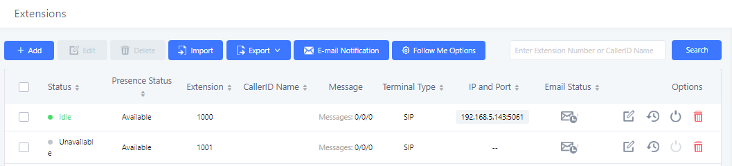
- Status
Users can see the following icon for each extension to indicate the SIP status.
![]() Green: Free
Green: Free
![]() Blue: Ringing
Blue: Ringing
![]() Yellow: In Use
Yellow: In Use
![]() Grey: Unavailable
Grey: Unavailable
- Edit single extension
Click on ![]() to start editing the extension parameters.
to start editing the extension parameters.
Click on ![]() to reset the extension parameters to default (except concurrent registration).
to reset the extension parameters to default (except concurrent registration).
Other settings will be restored to default in Maintenance🡪User Management🡪User Information except username and permissions and delete the user voicemail prompt and voice messages.
- Reboot the user
Click on ![]() to send NOTIFY reboot event to the device which has an UCM6510 extension already registered. To successfully reboot the user, “Zero Config” needs to be enabled on the UCM6510 Web GUI🡪Value-added Features🡪Zero Config🡪Auto Provisioning Settings.
to send NOTIFY reboot event to the device which has an UCM6510 extension already registered. To successfully reboot the user, “Zero Config” needs to be enabled on the UCM6510 Web GUI🡪Value-added Features🡪Zero Config🡪Auto Provisioning Settings.
- Delete selected extensions
Click on the ![]() button to delete a single extension. Users can also select multiple extensions and click on the Delete button to delete several extensions at once.
button to delete a single extension. Users can also select multiple extensions and click on the Delete button to delete several extensions at once.
- Modify selected extensions
Select the checkbox for the extension(s). Then click on “Modify Selected Extensions” to edit the extensions in a batch.
Export Extensions
UCM extensions can be exported to a CSV file. Different extension types (SIP, IAX, FXS) cannot be exported to the same CSV file. To export extensions, click on the Export button and select the extension type to export.
Users can also use the exported CSV file to use as a template to manually edit extension information.
Import Extensions
The capability to import extensions to the UCM6510 provides users flexibility to batch add extensions with similar or different configurations quickly.
- Export extension csv file from the UCM6510 by clicking on “Export Extensions” button.
- Fill up the extension information you would like in the exported csv template.
- Click on “Import Extensions” button. The following dialog will be prompted.
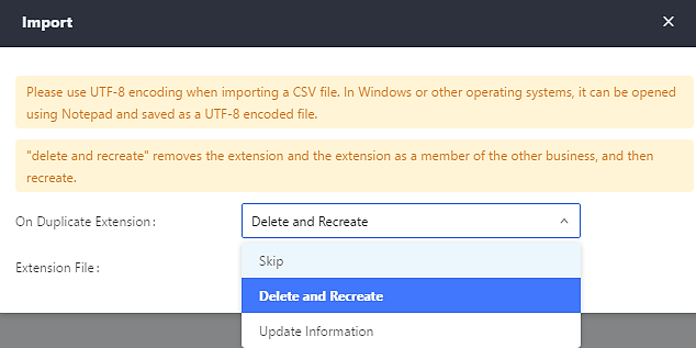
- Select the option in “On Duplicate Extension” to define how the duplicate extension(s) in the imported csv file should be treated by the PBX.
- Skip: Duplicate extensions in the csv file will be skipped. The PBX will keep the current extension information as previously configured without change.
- Delete and Recreate: The current extension previously configured will be deleted and the duplicate extension in the csv file will be loaded to the PBX.
- Update Information: The current extension previously configured in the PBX will be kept. However, if the duplicate extension in the csv file has different configuration for any options, it will override the configuration for those options in the extension.
- Click on “choose file to upload” to select csv file from local directory in the PC for uploading.
- Click on “Save” to import the csv file.
- Click on “Apply Changes” to apply the imported file on the UCM6510.
Note: The imported file should look like the following:
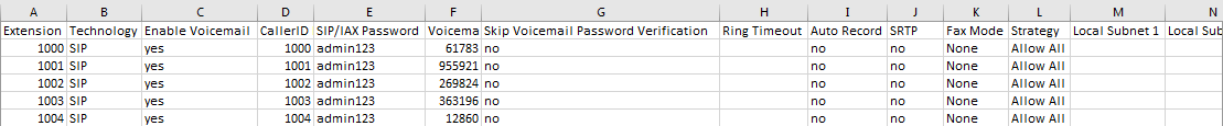
|
Field |
Supported values |
|
Extension |
Digits |
|
Technology |
SIP/SIP(WebRTC) |
|
Enable Voicemail |
yes/no/remote |
|
CallerID Number |
Digits |
|
SIP/IAX Password |
Alphanumeric characters |
|
Voicemail Password |
Digits |
|
Skip Voicemail Password Verification |
yes/no |
|
Ring Timeout |
Empty/ 3 to 600 (in second) |
|
SRTP |
yes/no |
|
Fax Mode |
None/Fax Detection |
|
Strategy |
Allow All/Local Subnet Only/A Specific IP Address |
|
Local Subnet 1 |
IP address/Mask |
|
Local Subnet 2 |
IP address/Mask |
|
Local Subnet 3 |
IP address/Mask |
|
Local Subnet 4 |
IP address/Mask |
|
Local Subnet 5 |
IP address/Mask |
|
Local Subnet 6 |
IP address/Mask |
|
Local Subnet 7 |
IP address/Mask |
|
Local Subnet 8 |
IP address/Mask |
|
Local Subnet 9 |
IP address/Mask |
|
Local Subnet 10 |
IP address/Mask |
|
Specific IP Address |
IP address |
|
Skip Trunk Auth |
yes/no/bytime |
|
Codec Preference | PCMU,PCMA,GSM,G.726,G.722,G.729,H.264, ILBC, AAL2-G.726-32, ADPCM, G.723, H.263, H.263p, vp8, opus |
|
Permission |
Internal/Local/National/International |
|
NAT |
yes/no |
|
DTMF Mode |
RFC4733/info/inband/auto |
|
Insecure |
Port |
|
Enable Keep-alive |
Yes/no |
|
Keep-alive Frequency |
Value from 1-3600 |
|
AuthID |
Alphanumeric value without special characters |
|
TEL URI |
Disabled/user=phone/enabled |
|
Call Forward Busy |
Digits |
|
Call Forward No Answer |
Digits |
|
Call Forward Unconditional |
Digits |
|
Support Hot-Desking Mode |
Yes/no |
|
Dial Trunk Password |
Digits |
|
Disable This Extension |
Yes/no |
|
CFU Time Condition |
All time/Office time/out of office time/holiday/out of holiday/out of office time or holiday/specific time |
|
CFN Time Condition |
All time/Office time/out of office time/holiday/out of holiday/out of office time or holiday/specific time |
|
CFB Time Condition |
All time/Office time/out of office time/holiday/out of holiday/out of office time or holiday/specific time |
|
Music On Hold |
Default/ringbacktone_default |
|
CC Agent Policy |
If CC is disabled use: never If CC is set to normal use: generic If CC is set to trunk use: native |
|
CC Monitor Policy |
Generic/never |
|
CCBS Available Timer |
3600/4800 |
|
CCNR Available Timer |
3600/7200 |
|
CC Offer Timer |
60/120 |
|
CC Max Agents |
Value from 1-999 |
|
CC Max Monitors |
Value from 1-999 |
|
Ring simultaneously |
Yes/no |
|
External Number |
Digits |
|
Time Condition for Ring Simultaneously |
All time/Office time/out of office time/holiday/out of holiday/out of office time or holiday/specific time |
|
Time Condition for Skip Trunk Auth |
All time/Office time/out of office time/holiday/out of holiday/out of office time or holiday/specific time |
|
Enable LDAP |
Yes/no |
|
Enable T.38 UDPTL |
Yes/no |
|
Max Contacts |
Values from 1-10 |
|
Enable WebRTC |
Yes/no |
|
Alert-Info |
None/Ring 1/Ring2/Ring3/Ring 4/Ring 5/Ring 6/Ring 7/ Ring 8/Ring 9/Ring 10/bellcore-dr1/bellcore-dr2/ bellcore-dr3/ bellcore-dr4/ bellcore-dr5/custom |
|
Do Not Disturb |
Yes/no |
|
DND Time Condition |
All time/Office time/out of office time/holiday/out of holiday/out of office time or holiday/specific time |
|
Custom Auto answer |
Yes/no |
|
Do Not Disturb Whitelist |
Empty/digits |
|
User Password |
Alphanumeric characters. |
|
First Name |
Alphanumeric without special characters. |
|
Last Name |
Alphanumeric without special characters. |
|
Email Address |
Email address |
|
Language |
Default/en/zh |
|
Phone Number |
Digits |
|
Call-Barging Monitor |
Extensions allowed to call barging |
|
Seamless Transfer Members |
Extensions allowed to seamless transfer |
|
Field |
Supported values |
|
Extension |
Digits |
|
Technology |
IAX |
|
Enable Voicemail |
yes/no |
|
CallerID Number |
Digits |
|
SIP/IAX Password |
Alphanumeric characters |
|
Voicemail Password |
Digits |
|
Skip Voicemail Password Verification |
yes/no |
|
Ring Timeout |
Empty/ 3 to 600 (in second) |
|
SRTP |
yes/no |
|
Fax Mode |
None/Fax Detection |
|
Strategy |
Allow All/Local Subnet Only/A Specific IP Address |
|
Local Subnet 1 |
IP address/Mask |
|
Local Subnet 2 |
IP address/Mask |
|
Local Subnet 3 |
IP address/Mask |
|
Local Subnet 4 |
IP address/Mask |
|
Local Subnet 5 |
IP address/Mask |
|
Local Subnet 6 |
IP address/Mask |
|
Local Subnet 7 |
IP address/Mask |
|
Local Subnet 8 |
IP address/Mask |
|
Local Subnet 9 |
IP address/Mask |
|
Local Subnet 10 |
IP address/Mask |
|
Specific IP Address |
IP address |
|
Skip Trunk Auth |
yes/no/bytime |
|
Codec Preference | PCMU,PCMA,GSM,G.726,G.722,G.729,H.264,ILBC,AAL2-G.726-32,ADPCM,G.723,H.263,H.263p,vp8,opus. |
|
Permission |
Internal/Local/National/International |
|
NAT |
yes/no |
|
Call Forward Busy |
Digits |
|
Call Forward No Answer |
Digits |
|
Call Forward Unconditional |
Digits |
|
Require Call Token |
Yes/no/auto |
|
Max Number of Calls |
Values from 1-512 |
|
Dial Trunk Password |
Digits |
|
Disable This Extension |
Yes/no |
|
CFU Time Condition |
All time/Office time/out of office time/holiday/out of holiday/out of office time or holiday/specific time |
|
CFN Time Condition |
All time/Office time/out of office time/holiday/out of holiday/out of office time or holiday/specific time |
|
CFB Time Condition |
All time/Office time/out of office time/holiday/out of holiday/out of office time or holiday/specific time |
|
Music On Hold |
Default/ringbacktone_default |
|
Ring simultaneously |
Yes/no |
|
External Number |
Digits |
|
Time Condition for Ring Simultaneously |
All time/Office time/out of office time/holiday/out of holiday/out of office time or holiday/specific time |
|
Time Condition for Skip Trunk Auth |
All time/Office time/out of office time/holiday/out of holiday/out of office time or holiday/specific time |
|
Enable LDAP |
Yes/no |
|
Limit Max time (s) |
Empty |
|
Do Not Disturb |
Yes/no |
|
DND Time Condition |
All time/Office time/out of office time/holiday/out of holiday/out of office time or holiday/specific time |
|
Do Not Disturb Whitelist |
Empty/digits |
|
User Password |
Alphanumeric characters. |
|
First Name |
Alphanumeric without special characters. |
|
Last Name |
Alphanumeric without special characters. |
|
Email Address |
Email address |
|
Language |
Default/en/zh |
|
Phone Number |
Digits |
|
Call-Barging Monitor |
Extensions allowed to call barging |
|
Seamless Transfer Members |
Extensions allowed to seamless transfer |
|
Field |
Supported values |
|
Extension |
Digits |
|
Technology |
FXS |
|
Analog Station |
FXS1/FXS2 |
|
Enable Voicemail |
yes/no |
|
CallerID Number |
Digits |
|
Voicemail Password |
Digits |
|
Skip Voicemail Password Verification |
yes/no |
|
Ring Timeout |
Empty/ 3 to 600 (in second) |
|
Auto Record |
yes/no |
|
Fax Mode |
None/Fax Detection |
|
Skip Trunk Auth |
Yes/no/bytime |
|
Permission |
Internal/Local/National/International |
|
Call Forward Busy |
Digits |
|
Call Forward No Answer |
Digits |
|
Call Forward Unconditional |
Digits |
|
Call Waiting |
Yes/no |
|
Use # as SEND |
Yes/no |
|
RX Gain |
Values from -30🡪6 |
|
TX Gain |
Values from -30🡪6 |
|
MIN RX Flash |
Values from: 30 – 1000 |
|
MAX RX Flash |
Values from: 40 – 2000 |
|
Enable Polarity Reversal |
Yes/no |
|
Echo Cancellation |
On/Off/32/64/128/256/512/1024 |
|
3-Way Calling |
Yes/no |
|
Send CallerID After |
½ |
|
Dial Trunk Password |
Digits |
|
Disable This Extension |
Yes/no |
|
CFU Time Condition |
All time/Office time/out of office time/holiday/out of holiday/out of office time or holiday/specific time |
|
CFN Time Condition |
All time/Office time/out of office time/holiday/out of holiday/out of office time or holiday/specific time |
|
CFB Time Condition |
All time/Office time/out of office time/holiday/out of holiday/out of office time or holiday/specific time |
|
Music On Hold |
Default/ringbacktone_default |
|
CC Agent Policy |
If CC is disabled use: never If CC is set to normal use: generic If CC is set to trunk use: native |
|
CC Monitor Policy |
Generic/never |
|
CCBS Available Timer |
3600/4800 |
|
CCNR Available Timer |
3600/7200 |
|
CC Offer Timer |
60/120 |
|
CC Max Agents |
Value from 1-999 |
|
CC Max Monitors |
Value from 1-999 |
|
Ring simultaneously |
Yes/no |
|
External Number |
Digits |
|
Time Condition for Ring Simultaneously |
All time/Office time/out of office time/holiday/out of holiday/out of office time or holiday/specific time |
|
Time Condition for Skip Trunk Auth |
All time/Office time/out of office time/holiday/out of holiday/out of office time or holiday/specific time |
|
Enable LDAP |
Yes/no |
|
Enable Hotline |
Yes/no |
|
Hotline Type |
Immediate hotline/delay hotline |
|
Hotline Number |
Digits |
|
Limit Max time (s) |
Empty |
|
Do Not Disturb |
Yes/no |
|
DND Time Condition |
All time/Office time/out of office time/holiday/out of holiday/out of office time or holiday/specific time |
|
Do Not Disturb Whitelist |
Empty/digits |
|
User Password |
Alphanumeric characters. |
|
First Name |
Alphanumeric without special characters. |
|
Last Name |
Alphanumeric without special characters. |
|
Email Address |
Email address |
|
Language |
Default/en/zh |
|
Phone Number |
Digits |
|
Call-Barging Monitor |
Extensions allowed to call barging |
|
Seamless Transfer Members |
Extensions allowed to seamless transfer |
The CSV file should contain all the above fields, if one of them is missing or empty, the UCM6510 will display the following error message for missing fields.

Extension Details
Users can access the Extension Details by clicking on an extension number in the Extensions list page and quickly view information about it such as:
- Extension: Shows the Extension number.
- Status: Shows the status of the extension.
- Presence status: Indicates the Presence Status of this extension.
- Terminal Type: Shows the Type of the terminal using this extension (SIP, FXS…etc.).
- Caller ID Name: Reveals the Caller ID Name configured on the extension.
- Messages: Shows the messages stats.
- IP and Port: The IP address and the ports of the device using the extension.
- Email status: Show the Email status (sent, to be sent…etc.).
- Ring Group: Indicates the ring groups that this extension belongs to.
- Call Queue: Indicates the Cal Queues that this extension belongs to.
- Call Queue (Dynamic): Indicates the Call Queues that this extension belongs to as a dynamic agent.
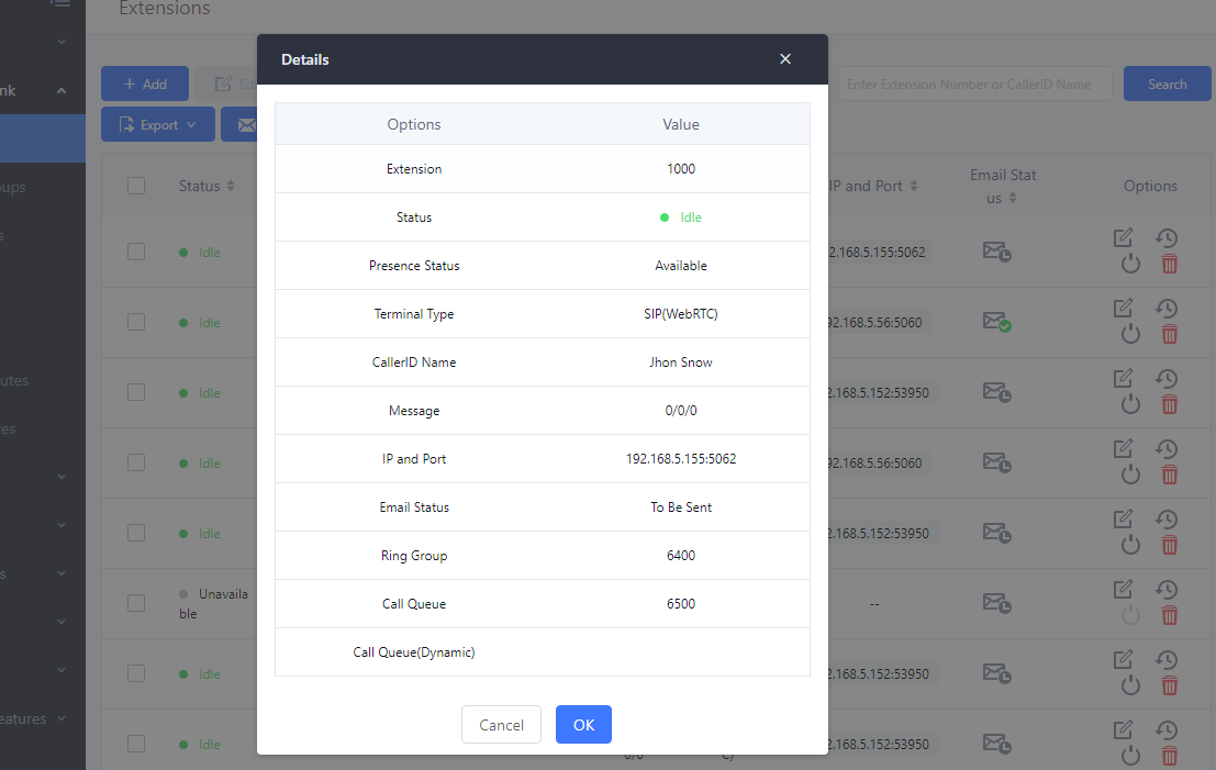
E-mail Notification
Users can request for their SIP account information via email. The system administrator can select the extensions to send account information emails to and press the Email Notification button in the Extensions page.
When click on “E-mail Notification” button, the following message will be prompted in the web page. Click on OK to confirm sending the account information to all users’ Email addresses. After clicking the button, the following prompt will appear:
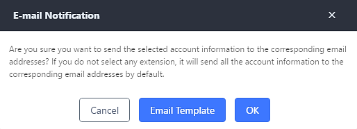
The selected users will receive emails containing account registration information, LDAP configuration, and QR codes for quick setup on mobile apps.
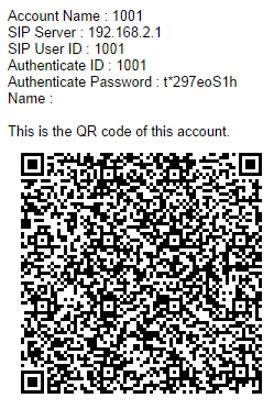
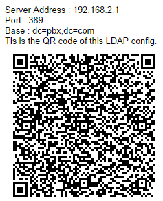
Multiple Registrations per Extension
UCM6510 supports multiple registrations per extension so that users can use the same extension on devices in different locations.
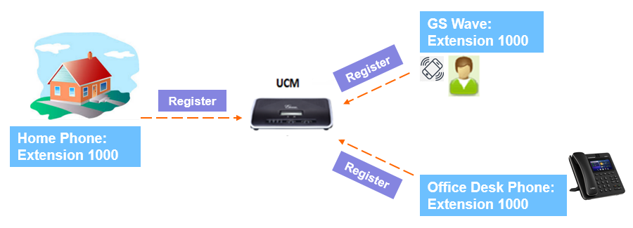
This feature can be enabled by configuring option “Concurrent Registrations” under Web GUI🡪Extension/Trunk🡪Edit Extension. The default value is 1 for security purposes. Maximum is 10.
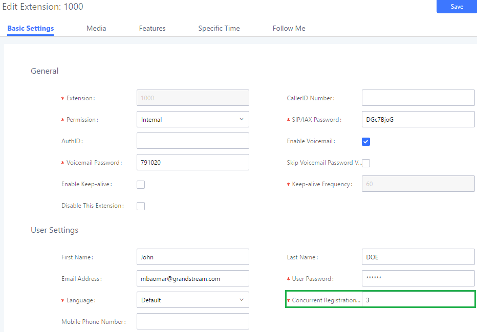
SMS Message Support
The UCM6510 provides built-in SIP SMS message support. For SIP end devices such as Grandstream GXP or GXV phones that supports SIP message, after an UCM6510 account is registered on the end device, the user can send and receive SMS message. Please refer to the end device documentation on how to send and receive SMS message.
SMS Message support is a new feature added since firmware 1.0.10.x.
Extension Groups
The UCM6510 extension group feature allows users to assign extensions to different groups to better manage the configurations on the PBX. For example, when configuring “Enable Filter on Source Caller ID”, users could select a group instead of each person’s extension to assign. This feature simplifies the configuration process and helps manage and categorize the extensions for business environment.
Configure Extension Groups
Extension group can be configured via Web GUI🡪Call Features🡪Extension Groups.
- Click on “Create New Extension Group” to create a new extension group.
- Click on to edit the extension group.
- Click on to delete the extension group.
Select extensions from the list on the left side to the right side.
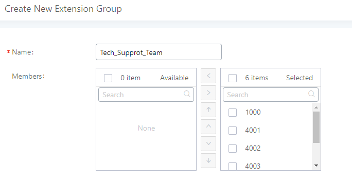
Click on ![]()
![]()
![]()
![]() in order to change the ringing priority of the members selected on the group.
in order to change the ringing priority of the members selected on the group.
Use Extension Groups
Here is an example where the extension group can be used. Go to Web GUI 🡪 Extension/Trunk 🡪 Outbound Routes and select “Enable Filter on Source Caller ID”. Both single extensions and extension groups will show up for users to select.
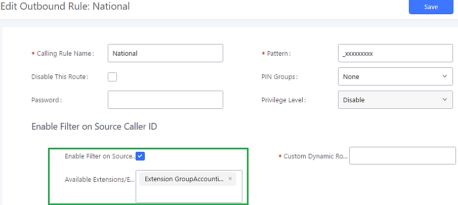
Analog Trunks
To set up analog trunk on the UCM6510:
- Go to Web GUI🡪Extension/Trunk🡪Analog Trunks to add and edit analog trunks.
- Go to Web GUI🡪PBX Settings🡪Interface Settings to configure analog hardware settings.
Analog Trunks Configuration
Go to Web GUI🡪Extension/Trunk🡪Analog Trunks to add and edit analog trunks.
- Click on “Create New Analog Trunk” to add a new analog trunk.
- Click on to edit the analog trunk.
- Click on to delete the analog trunk.
The analog trunk options are listed in the table below.
|
Channels |
Select the channel for the analog trunk. |
|
Trunk Name |
Specify a unique label to identify the trunk when listed in outbound routes, inbound routes and etc. |
|
Advanced Options | |
|
SLA Mode |
Enable this option to satisfy two primary use cases, which include emulating a simple key system and creating shared extensions on a PBX. Enable SLA Mode will disable polarity reversal. |
|
Barge Allowed |
The barge option specifies whether or not other stations are allowed to join a call in progress on this trunk. If enabled, the other stations can press the line button to join the call. The default setting is Yes. |
|
Hold Access |
The hold option specifies hold permissions for this trunk. If set to “Open”, any station can place this trunk on hold and any other station is allowed to retrieve the call. If set to “Private”, only the station that places the call on hold can retrieve the call. The default setting is Yes. |
|
Enable Polarity Reversal |
If enabled, a polarity reversal will be marked as received when an outgoing call is answered by the remote party. For some countries, a polarity reversal is used for signaling the disconnection of a phone line and the call will be considered as “hang up” on a polarity reversal. The default setting is “No”. |
|
Polarity on Answer Delay |
When FXO port answers the call, FXS may send a Polarity Reversal. If this interval is shorter than the value of “Polarity on Answer Delay”, the Polarity Reversal will be ignored. Otherwise, the FXO will on-hook to disconnect the call. The default setting is 600ms. |
|
Current Disconnect Threshold (ms) |
This is the periodic time (in ms) that the UCM6510 will use to check on a voltage drop in the line. The default setting is 200. Valid range is 50 to 3000. |
|
Ring Timeout |
Configure the ring timeout (in ms). Trunk (FXO) devices must have a timeout to determine if there was a hang up before the line is answered. This value can be used to configure how long it takes before the UCM6510 considers a non-ringing line with hang up activity. Default setting is 8000. |
|
RX Gain |
Configure the RX gain for the receiving channel of analog FXO port. The valid range is from -12.0 (Db) to + 12.0 (Db). The default setting is 0. |
|
TX Gain |
Configure the TX gain for the transmitting channel of analog FXO port. The valid range is from -12.0 (Db) to + 12.0 (Db). The default setting is 0. |
|
Use CallerID |
Configure to enable CallerID detection. The default setting is “Yes”. |
|
Caller ID Scheme |
Select the Caller ID scheme for this trunk.
If you are not sure which scheme to choose, please select “Auto Detect”. The default setting is “Bellcore/Telcordia”. |
|
Fax Mode |
Enable to detect Fax signal from the trunk during the call and send the received Fax to the default Email address in Fax setting page under Web GUI🡪Call Features🡪Fax/T.38. The default setting is “No”. Note: If enabled, Fax Pass-through cannot be used. |
|
FXO Dial Delay(ms) |
Configure the time interval between off-hook and first dialed digit for outbound calls. |
|
Auto Record |
Enable automatic recording for the calls using this trunk. The default setting is disabled. The recording files are saved in external storage device if plugged in and can be accessed under Web GUI🡪CDR🡪Recording Files. |
|
Disable This Trunk |
If selected, the trunk will be disabled and incoming/Outgoing calls via this trunk will not be possible. |
|
DAHDI Out Line Selection |
This is to implement analog trunk outbound line selection strategy. Three options are available:
The default setting is “Ascend” mode. |
|
Echo Cancellation Mode |
The Non-Linear Processing (NLP) in echo cancellation helps to remove/suppress residual echo components that could not be removed by the LEC (Line Echo Canceller). Following modes are supported:
|
|
Direct Callback |
Allows external numbers the option to get directed to the extension that last called them. For Example: User 2002 has dialed external number 061234575 but they were not reachable, once they have received missed call notification on their phone, they would mostly call back the number, if the option “Direct Callback” is enabled then they will be directly bridged to user 2002 regardless of the configured inbound destination. |
|
Tone Settings | |
|
Busy Detection |
Busy Detection is used to detect far end hang up or for detecting busy signal. The default setting is “Yes”. |
|
Busy Tone Count |
If “Busy Detection” is enabled, users can specify the number of busy tones to be played before hanging up. The default setting is 2. Better results might be achieved if set to 4, 6 or even 8. Please note that the higher the number is, the more time is needed to hang up the channel. However, this might lower the probability to get random hang up. |
|
Congestion Detection |
Congestion detection is used to detect far end congestion signal. The default setting is “Yes”. |
|
Congestion Count |
If “Congestion Detection” is enabled, users can specify the number of congestion tones to wait for. The default setting is 2. |
|
Tone Country |
Select the country for tone settings. If “Custom” is selected, users could manually configure the values for Busy Tone and Congestion Tone. The default setting is “United States of America (USA)”. |
|
Busy Tone |
Syntax: f1=val[@level][,f2=val[@level]],c=on1/off1[-on2/off2[-on3/off3]]; Frequencies are in Hz and cadence on and off are in ms. Frequencies Range: [0, 4000] Busy Level Range: (-300, 0) Cadence Range: [0, 16383]. Select Tone Country “Custom” to manually configure Busy Tone value. Default value: f1=480@-50,f2=620@-50,c=500/500 |
|
Congestion Tone |
Syntax: f1=val[@level][,f2=val[@level]],c=on1/off1[-on2/off2[-on3/off3]]; Frequencies are in Hz and cadence on and off are in ms. Frequencies Range: [0, 4000] Busy Level Range: (-300, 0) Cadence Range: [0, 16383]. Select Tone Country “Custom” to manually configure Busy Tone value. Default value: f1=480@-50,f2=620@-50,c=250/250 |
|
PSTN Detection |
Click on “Detect” to detect the busy tone, Polarity Reversal and Current Disconnect by PSTN. Before the detecting, please make sure there is more than one channel configured and working properly. If the detection has busy tone, the “Tone Country” option will be set as “Custom”. |
PSTN Detection
The UCM6510 provides PSTN detection function to help users detect the busy tone, Polarity Reversal and Current Disconnect by making a call from the PSTN line to another destination. The detecting call will be answered and up for about 1 minute. Once done, the detecting result will show and can be used for the UCM6510 settings.
- Go to UCM6510 Web GUI🡪Extension/Trunk🡪Analog Trunks page.
- Click to edit the analog trunk created for the FXO port.
- In the dialog window to edit the analog trunk, go to “Tone Settings” section and click on “Detect” for “PSTN Detection”.
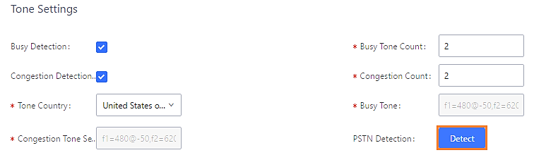
- Click on “Detect” to start PSTN detection.
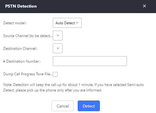
- If there are two FXO ports connected to PSTN lines, use the following settings for auto-detection.
Detect Model: Auto Detect.
Source Channel: The source channel to be detected.
Destination Channel: The channel to help detecting. For example, the second FXO port.
Destination Number: The number to be dialed for detecting. This number must be the actual PSTN number for the FXO port used as the destination channel.
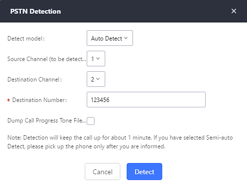
- If there is only one FXO port connected to PSTN line, use the following settings for auto-detection.
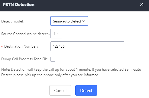
Detect Model: Semi-auto Detect.
Source Channel: The source channel to be detected.
Destination Number: The number to be dialed for detecting. This number could be a cell phone number or other PSTN number that can be reached from the source channel PSTN number.
- Click “Detect” to start detecting. The source channel will initiate a call to the destination number. For “Auto Detect”, the call will be automatically answered. For “Semi-auto Detect”, the UCM6510 Web GUI will display prompt to notify the user to answer or hang up the call to finish the detecting process.
- Once done, the detected result will show. Users could save the detecting result as the current UCM6510 settings.
|
Detect Model |
Select “Auto Detect” or “Semi-auto Detect” for PSTN detection.
Please make sure two or more channels are connected to the UCM6510 and in idle status before starting the detection. During the detection, one channel will be used as caller (Source Channel) and another channel will be used as callee (Destination Channel). The UCM6510 will control the call to be established and hang up between caller and callee to finish the detection.
Semi-auto detection requires answering or hanging up the call manually. Please make sure one channel is connected to the UCM6510 and in idle status before starting the detection. During the detection, source channel will be used as caller and send the call to the configured Destination Number. Users will then need follow the prompts in Web GUI to help finish the detection. The default setting is “Auto Detect”. |
|
Source Channel |
Select the channel to be detected. |
|
Destination Channel |
Select the channel to help detect when “Auto Detect” is used. |
|
Destination Number |
Configure the number to be called to help the detection. |
DAHDI and Analog Hardware Configuration
Analog Hardware
The analog hardware (FXS port and FXO port) on the UCM6510 can be configured under Web GUI🡪PBX Settings🡪Interface Settings. Click on ![]() to edit signaling preference for FXS port or configure ACIM settings for FXO port.
to edit signaling preference for FXS port or configure ACIM settings for FXO port.
Select “Loop Start” or “Kewl Start” for each FXS port. And then click on “Update” to save the change.
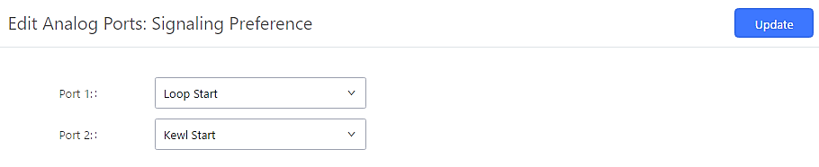
For FXO port, users could manually enter the ACIM settings by selecting the value from dropdown list for each port. Or users could click on “Detect” and choose the detection algorithm, two algorithms exist (ERL, Pr) for the UCM6510 to automatically detect the ACIM value. The detecting value will be automatically filled into the settings.
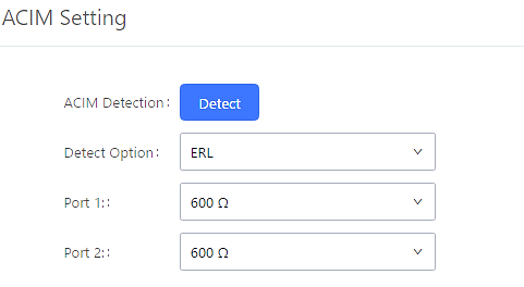
|
Tone Region |
Select country to set the default tones for dial tone, busy tone, ring tone and etc to be sent from the FXS port. The default setting is “United States of America (USA)”. |
|
Advanced Settings | |
|
FXO Opermode |
Select country to set the On-Hook Speed, Ringer Impedance, Ringer Threshold, Current Limiting, TIP/RING voltage adjustment, Minimum Operational Loop Current, and AC Impedance as predefined for your country’s analog line characteristics. The default setting is “USA”. |
|
FXS Opermode |
Select country to set the On-Hook Speed, Ringer Impedance, Ringer Threshold, Current Limiting, TIP/RING voltage adjustment, Minimum Operational Loop Current, and AC Impedance as predefined for your country’s analog line characteristics. The default setting is “United States of America (USA)”. |
|
FXS TISS Override |
Configure to enable or disable override Two-Wire Impedance Synthesis (TISS). The default setting is No. If enabled, users can select the impedance value for Two-Wire Impedance Synthesis (TISS) override. The default setting is 600Ω. |
|
PCMA Override |
Select the codec to be used for analog lines. North American users should choose PCMU. All other countries, unless already known, should be assumed to be PCMA. The default setting is PCMU. Note: This option requires system reboot to take effect. |
|
Boost Ringer |
Configure whether normal ringing voltage (40V) or maximum ringing voltage (89V) for analog phones attached to the FXS port is required. The default setting is “Normal”. |
|
Fast Ringer |
Configure to increase the ringing speed to 25HZ. This option can be used with “Low Power” option. The default setting is “Normal”. |
|
Low Power |
Configure the peak voltage up to 50V during “Fast Ringer” operation. This option is used with “Fast Ringer”. The default setting is “Normal”. |
|
Ring Detect |
If set to “Full Wave”, false ring detection will be prevented for lines where Caller ID is sent before the first ring and proceeded by a polarity reversal, as in UK. The default setting is “Standard”. |
|
FXS MWI Mode |
Configure the type of Message Waiting Indicator on FXS lines. The default setting is “FSK”.
|
|
Allows users to adjust the tolerance of the FXO ringing frequency. 63Hz is considered the standard value and is selected by default. |
When users encounter issues such as audio delay in outbound calls using the analog trunk, they can adjust DAHDI settings on the UCM to attempt to lessen or resolve the issues.
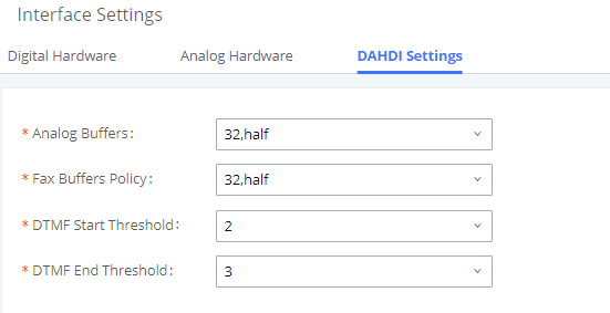
For the value of the option such as “32, half”:
The number in the option indicates the number of read/write buffers for TDM (DAHDI).
The “Half”, “Immediate” or “Full” option indicates the strategy when reading/writing data from buffer.
- “Half”: Data will be read/written from buffer when half of the buffer is occupied with data.
- “Immediate”: Read/write from buffer whenever there is data occupying the buffer.
- “Full”: Data will be read/written from buffer when buffer is fully occupied with data.
DTMF Start Threshold: Indicates the minimum number of times a single DTMF must be detected in a signal before it is considered valid.
DTMF End Threshold: Indicates the minimum number of times an end signal for a single DTMF number must be detected before it is considered valid.
Normally, DAHDI settings should be kept default and should be adjusted only when users encounter analog trunk/Fax-related issues.
Digital Trunks
The UCM6510 supports E1/T1/J1 which are physical connection technology used in digital network. E1 is the European standard, T1 is the North American standard, and J1 is the Japanese standard.
UCM6510 supports four signaling protocols: PRI, MFC/R2, SS7, E&M Immediate and E&M Wink. PRI provides a varying number of channels depending on the standards in the country of implementation (E1, T1 or J1); MFC/R2 is a signaling protocol heavily used over E1 trunks; SS7 uses out-of-band signaling, which travels on a separate, dedicated channel rather than within the same channel as the telephone call, providing more efficiency and higher security level when the telephone calls are set up. E&M Immediate and E&M Wink are only valid when using T1 port.
To set up digital trunk on the UCM6510:
- Go to Web GUI🡪PBX Settings🡪Interface Settings🡪Digital Hardware to configure port type and channels.
- Go to Web GUI🡪Extension/Trunk🡪Digital Trunks to add and edit digit trunk.
- Go to Web GUI🡪Extension/Trunk🡪Outbound Routes and Inbound Routes to configure outbound and inbound rule for the digital trunk.
Digital Hardware Configuration
Go to Web GUI🡪 PBX Settings🡪Interface Settings🡪Digital Hardware page and configure the following:
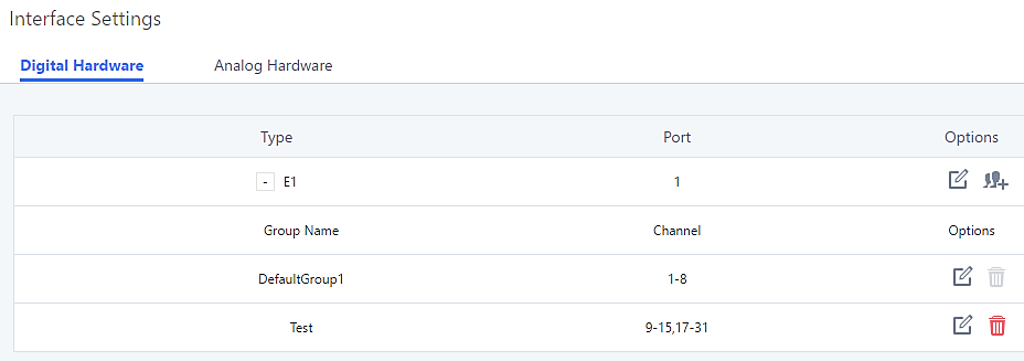
- Step 1: Click on to edit digital ports. Please see configuration parameters in the tables below.
- Step 2: Click on to edit group. This assigns channels to be used for the digital port. For E1, 30 B channels can be assigned to the default group; for T1/J1, 23 B channels can be assigned to the default group.
- Step 3: If fewer than 30 B channels for E1 or 23 B channels for T1/J1 are assigned in default group, users can click on
 to add more groups. This is not necessary in most cases and only default group is needed.
The UCM6510 currently supports E1, T1 and J1 digital hardware type. When different signaling is selected for E1, T1 or J1, the settings in basic options and advanced options will be different. The following tables list all the settings to configure digital ports when selecting each signaling.
Basic Settings | |
Clock | All E1/T1/J1 spans generate a clock signal on their transmit side. The parameter determines whether the clock signal from the far end of the E1/T1/J1 is used as the master source of clock timing. If the far end is used as the master, the PBX system clock will synchronize to it. Master: The port will never be used as a source of timing. This is appropriate when you know the far end should always be a slave to you. Slave: The equipment at the far end of the E1/T1/J1 link is the preferred source of the master clock. |
LBO | The line build-out (LBO) is the distance between the operators and the PBX. Please use the default value 0Db unless the distance is long. |
RX Gain | Configure the RX gain for the receiving channel of digital port. The valid range is from -24Db to +12Db. |
TX Gain | Configure the TX Gain for the transmitting channel of digital port. The valid range is -24Db to +12Db. |
Codec | Select alaw or ulaw. If set to default, alaw will be used for E1. |
Play Local RBT | Configure whether to play the ringback tone from local UCM6510 or not. If enabled, the local UCM6510 will play ringback tone to the caller. Otherwise, the caller will listen to the tone from peer device. Default setting is disabled. |
Advanced Settings | |
Switch Type | Select switch type. - EuroISDN: EuroISDN (common in Europe) - NI2: National ISDN type 2 (common in the US) - DMS100: Nortel DMS100 - 4ESS: AT&T 4ESS - 5ESS: Lucent 5ESS - NI1: old national ISDN type 1 - Q.SIG |
Coding | Select "HDB3" or "AMI". |
CRC | Select whether to use CRC4 or not. |
PRI Dial Plan | This setting is used to specify the type of the callee number. The service provider will usually verify this. The default setting is "unknown". In some very unusual circumstances, you may need set to "Dynamic" or "Redundant". Note: When one type is selected, you might not be able to dial another playlist of numbers. For example, if "National" is configured, you will not be able to dial local or international numbers. |
PRI Local Dial Plan | This setting is used to specify the type of the caller number. The service provider will usually verify this. |
D-Chan | Indicates the D channel for control. |
International Prefix National Prefix Local Prefix Private Prefix Unknown Prefix | Configure the prefix in PRI Local Dial Plan and PRI Dial Plan for each type. |
PRI T310 | Configure PRI T310 Timer (in seconds). The default value is 10 seconds. |
PRI Indication | Select the PRI Indication. outofband: Use RELEASE, DISCONNECT or other messages with CAUSE to indicate call progress (e.g., cause: unassigned number or user busy). inband: use in-band tones to play busy or congestion signal to the other side. This is the default setting. |
Reset Interval | The interval that restarts idle channels. |
PRI Exclusive | This setting is used to set up the ChannelID in SETUP message. If enabled, only the specified B channel can be used. Otherwise, select one of the channels in B channel. If you need override the existing channels selection routine and force all PRI channels to be marked as exclusively selected, please enable it. |
Facility Enable | If selected, transmission of facility-based ISDN supplementary services (such as caller name from CPE over facility) will be enabled. |
SETUP ACK | When receving a remote "SETUP" SIP message, and the "Sending Complete" field is not included in it, the UCM will send a "SETUP ACK" to request for more information. This option should be used if a remote device has "SETUP ACK" support issues. |
Overlap Dial | Configure this option to send overlap digits. If enabled, SETUP message can include some digits of callee number, and rest of the digits can be sent using INFORMATION message. If disabled, callee number will be sent via SETUP message when all the digits are ready. |
NSF | Some switches (AT&T especially) require network specific facility. Currently the supported values are "none", "sdn", "megacom", "tollfreemegacom". |
Discard Remote Hold Signal | When this option is enabled, the UCM6510 will ignore the call hold signal of the other party. |
|
Basic Settings | |
|
Clock |
All E1/T1/J1 spans generate a clock signal on their transmit side. The parameter determines whether the clock signal from the far end of the E1/T1/J1 is used as the master source of clock timing. If the far end is used as the master, the PBX system clock will synchronize to it.
|
|
SS7 Variant |
Select ITU, ANSI or CHINA. |
|
Originating Point Code |
Originating point code is used to identify the node originating the message, always provided by the operator/ISP.
|
|
Destination Point Code |
Destination point code is the address to send the message to, always be provided by the operator/ISP.
|
|
First CIC |
When Span Type is E1, ITU & CHINA Range: [0, 4065], ANSI Range: [0, 16353]. When Span Type is T1/J1, ITU & CHINA Range: [0, 4072], ANSI Range: [0, 16360]. |
|
Assign CIC To D-channel |
If set to yes, D-channel will be assigned a CIC. Else, D-channel will not be assigned. By default, it is set to No. |
|
Network Indicator |
Network Indicator (NI) should match in nodes, otherwise it might cause issues. Users can select “National”, “National Spare”, “International”, or “International Spare”. Usually “National” or “International” is used. |
|
LBO |
The line build-out (LBO) is the distance between the operators and the PBX. Please use the default value 0dB unless the distance is long. |
|
RX Gain |
Configure the RX gain for the receiving channel of digital port. The valid range is from -24dB to +12dB. |
|
TX Gain |
Configure the TX Gain for the transmitting channel of digital port. The valid range is -24dB to +12dB. |
|
Codec |
Select alaw or ulaw. If set to default, alaw will be used for E1. |
|
Advanced Settings | |
|
Coding |
Select “HDB3” or “AMI”. |
|
CRC |
Select whether to use CRC4 or not. |
|
Called Nature of Address Indicator |
Indicates the type of the called number. The receiving switch may use this indicator during translations to apply the number’s proper dial plan. Users can select “Unknown”, “Subscriber”, “National”, “International” or “Dynamic”. |
|
Calling Nature of Address Indicator |
Indicates the type of the calling number. The receiving switch may use this indicator during translations to apply the number’s proper dial plan. Users can select “Unknown”, “Subscriber”, “National”, “International” or “Dynamic”. |
|
D-Chan |
Indicates the D channel for control |
|
International Prefix National Prefix Subscriber Prefix Unknown Prefix |
Configure the prefix in Called Nature of Address Indicator and Calling Nature of Address Indicator for each type. |
|
Basic Settings | |
|
Clock |
All E1/T1/J1 spans generate a clock signal on their transmit side. The parameter determines whether the clock signal from the far end of the E1/T1/J1 is used as the master source of clock timing. If the far end is used as the master, the PBX system clock will synchronize to it.
|
|
Variant |
MFC/R2 multinational adaption. UCM6510 supports MFC/R2 standards by ITU and MFC/R2 standards in different countries or regions including Argentina, Brazil, China, Czech Republic, Colombia, Ecuador, Indonesia, Mexico, the Philippines and Venezuela. |
|
Get ANI First |
If enabled, the callee side will request the caller to send caller number first and then called number. Note: Options “Get ANI First” and “Skip Category” cannot be enabled at the same time. |
|
Category |
Select the category of the caller. UCM6510 supports four categories: National Subscriber, National Priority Subscriber, International Subscriber and International Priority Subscriber. |
|
LBO |
The line build-out (LBO) is the distance between the operators and the PBX. Please use the default value 0dB unless the distance is long. |
|
RX Gain |
Configure the RX gain for the receiving channel of digital port. The valid range is from -24dB to +12dB. |
|
TX Gain |
Configure the TX Gain for the transmitting channel of digital port. The valid range is -24dB to +12dB. |
|
Play Local RBT |
This configured whether to play the ringback tone from local UCM6510 or not. If enabled, the local UCM6510 will play ringback tone to the caller. Otherwise, the caller will listen to the tone from peer device. The default setting is disabled. |
|
Advanced Settings | |
|
Coding |
Select “HDB3” or “AMI”. |
|
CRC |
Select whether to use CRC4 or not. |
|
MF Back Timeout (ms) |
MFC/R2 value in milliseconds for MF timeout. Values smaller than 500ms are not recommended. -1 represents default value. |
|
Metering Pulse Timeout (ms) |
MFC/R2 value in milliseconds for the metering pulse timeout. Metering pulse is sent by some telcos for some R2 variants during a call for billing purposes to indicate costs. Should not last more than 500ms, -1 represents default value, and for Argentina the default value is 400ms, for others is 0ms. |
|
Allow Collect Calls |
Brazil has a special calling party category for collect calls (llamadas por cobrar) instead of using the operator (as in Mexico). The R2 spec in Brazil says a special GB tone should be used to reject collect calls. By default, this is disabled, which means collect calls will be blocked. |
|
Double Answer |
Some PBXs require a double-answer process to block collect calls. If users have problem blocking collect calls using Group B signals, please try enabling this option. |
|
Accept On Offer |
By default, it is enabled. In most of cases, this option should be enabled. |
|
Skip Category |
If enabled, the callee side will request the caller to send caller category before sending caller number. Note: “Get ANI First” and “Skip Category” cannot be enabled at the same time. |
|
Charge Calls |
Whether or not report to the other end “accept call with charge”. This setting has no effect with most telecos. The default setting is enabled (recommended). |
|
Custom Options |
Click on “Custom Options” button (on the right top of the configuration dialog) and then user can customize desired tone and timer options accordingly. |
|
Basic Settings | |
|
Clock |
All E1/T1/J1 spans generate a clock signal on their transmit side. The parameter determines whether the clock signal from the far end of the E1/T1/J1 is used as the master source of clock timing. If the far end is used as the master, the PBX system clock will synchronize to it.
|
|
LBO |
The line build-out (LBO) is the distance between the operators and the PBX. Please use the default value 0dB unless the distance is long. |
|
RX Gain |
Configure the RX gain for the receiving channel of digital port. The valid range is from -24dB to +12dB. |
|
TX Gain |
Configure the TX Gain for the transmitting channel of digital port. The valid range is -24dB to +12dB. |
|
Codec |
Select alaw or ulaw. If set to default, ulaw will be used for T1/J1. |
|
Play Local RBT |
This configured whether to play the ringback tone from local UCM6510 or not. If enabled, the local UCM6510 will play ringback tone to the caller. Otherwise, the caller will listen to the tone from peer device. The default setting is disabled. |
|
Framing |
Select “esf” or “d4”. Default setting is esf. |
|
Advanced Settings | |
|
Switch Type |
Select switch type.
|
|
Coding |
Select “B8ZS” or “AMI”. |
|
PRI Dial Plan |
This setting is used to specify the type of the callee number. The service provider will usually verify this. The default setting is “unknown”. In some very unusual circumstances, you may need set to “Dynamic” or “Redundant”. Note: When one type is selected, you might not be able to dial another playlist of numbers. For example, if “National” is configured, you will not be able to dial local or international numbers. |
|
PRI Local Dial Plan |
This setting is used to specify the type of the caller number. The service provider will usually verify this. |
|
D-Chan |
Indicates the D channel for control. |
|
International Prefix National Prefix Local Prefix Private Prefix Unknown Prefix |
Configure the prefix in PRI Local Dial Plan and PRI Dial Plan for each type. |
|
PRI T310 |
Configure PRI T310 Timer (in seconds). The default value is 10 seconds. |
|
PRI Indication |
Select the PRI Indication.
|
|
Reset Interval |
The interval that restarts idle channels. |
|
PRI Exclusive |
This setting is used to set up the ChannelID in SETUP message. If enabled, only the specified B channel can be used. Otherwise, select one of the channels in B channel. If you need override the existing channels selection routine and force all PRI channels to be marked as exclusively selected, please enable it. |
|
Facility Enable |
If selected, transmission of facility-based ISDN supplementary services (such as caller name from CPE over facility) will be enabled. |
|
Overlap Dial |
Configure this option to send overlap digits. If enabled, SETUP message can include some digits of callee number, and rest of the digits can be sent using INFORMATION message. If disabled, callee number will be sent via SETUP message when all the digits are ready. |
|
NSF |
Some switches (AT&T especially) require network specific facility. Currently the supported values are “none”, “sdn”, “megacom”, “tollfreemegacom”, “accunet”. |
|
Basic Settings | |
|
Clock |
All E1/T1/J1 spans generate a clock signal on their transmit side. The parameter determines whether the clock signal from the far end of the E1/T1/J1 is used as the master source of clock timing. If the far end is used as the master, the PBX system clock will synchronize to it.
|
|
SS7 Variant |
Select ITU, ANSI or CHINA. |
|
Originating Point Code |
Originating point code is used to identify the node originating the message, always provided by the operator/ISP.
|
|
Destination Point Code |
Destination point code is the address to send the message to, always be provided by the operator/ISP.
|
|
First CIC |
When Span Type is E1, ITU & CHINA Range: [0, 4065], ANSI Range: [0, 16353]. When Span Type is T1/J1, ITU & CHINA Range: [0,4072], ANSI Range: [0, 16360]. |
|
Assign CIC to D-Channel |
If set to yes, D-channel will be assigned with a CIC. Else, D-channel will not be assigned with a CIC. By default, it is set to No. |
|
Network Indicator |
Network Indicator (NI) should match in nodes, otherwise it might cause issues. Users can select “National”, “National Spare”, “International”, or “International Spare”. Usually “National” or “International” is used. |
|
LBO |
The line build-out (LBO) is the distance between the operators and the PBX. Please use the default value 0dB unless the distance is long. |
|
RX Gain |
Configure the RX gain for the receiving channel of digital port. The valid range is from -24dB to +12dB. |
|
TX Gain |
Configure the TX Gain for the transmitting channel of digital port. The valid range is -24dB to +12dB. |
|
Codec |
Select alaw or ulaw. If set to default, ulaw will be used for T1/J1. |
|
Framing |
Select “esf” or “d4”. Default setting is esf. |
|
Advanced Settings | |
|
Coding |
Select “B8ZS” or “AMI”. |
|
Called Nature of Address Indicator |
Indicates the type of the called number. The receiving switch may use this indicator during translations to apply the number’s proper dial plan. Users can select “Unknown”, “Subscriber”, “National”, “International” or “Dynamic”. |
|
Calling Nature of Address Indicator |
Indicates the type of the calling number. The receiving switch may use this indicator during translations to apply the number’s proper dial plan. Users can select “Unknown”, “Subscriber”, “National”, “International” or “Dynamic”. |
|
D-Chan |
Indicates the D channel for control. |
|
International Prefix National Prefix Subscriber Prefix Unknown Prefix |
Configure the prefix in Called Nature of Address Indicator and Calling Nature of Address Indicator for each type. |
|
Basic Setting | |
|
Clock |
All E1/T1/J1 spans generate a clock signal on their transmit side. The parameter determines whether the clock signal from the far end of the E1/T1/J1 is used as the master source of clock timing. If the far end is used as the master, the PBX system clock will synchronize to it.
|
|
RX Gain |
Configure the RX gain for the receiving channel of digital port. The valid range is from -24dB to +12dB. |
|
TX Gain |
Configure the TX Gain for the transmitting channel of digital port. The valid range is -24dB to +12dB. |
|
Codec |
Select alaw or ulaw. The default codec is ulaw for T1. |
|
Framing |
Select “esf” or “d4”. Default setting is esf. |
|
Advanced Settings | |
|
Coding |
Select B8ZS or AMI. The default setting is B8ZS for T1. |
|
OutgoingDialDelay |
The option is only valid for E&M Wink signaling. The dial delay interval after received WINK event in an outgoing call. The default value is 200ms. |
|
rxwink |
Configure receive wink timing. The default setting is 300ms. |
Digital Trunk Configuration
After configuring digital hardware, go to Web GUI🡪Extension/Trunk🡪Digital Trunks.
- Click on “Create New Digital Trunk” to add a new digital trunk.
- Click on to configure detailed parameters for the digital trunk.
- Click on
 to configure Direct Outward Dialing (DOD) for the digital Trunk.
 - Click on to delete the digital trunk.
The digital trunk parameters are listed in the table below.
|
Trunk Name |
Configure trunk name to identify the digital trunk. |
|
Channel Group |
Configure the digital channel group used by the trunk. |
|
Hide CallerID |
Configure to hide outgoing caller ID. The default setting is “No”. |
|
Keep Trunk CID |
If enabled, the trunk CID will not be overridden by extension’s CID when the extension has CID configured. The default setting is “No”. |
|
Caller ID |
Configure the Caller ID. This is the number that the trunk will try to use when making outbound calls. For some providers, it might not be possible to set the CallerID with this option and this option will be ignored. Important Note: When making outgoing calls, the following priority order rule will be used to determine which CallerID will be set before sending out the call: From user (Register Trunk Only) 🡪 CID from inbound call (Keep Original CID Enabled) 🡪 Trunk Username/CallerID (Keep Trunk CID Enabled) 🡪 DOD 🡪 Extension CallerID Number 🡪 Trunk Username/CallerID (Keep Trunk CID Disabled) 🡪 Global Outbound CID. |
|
CallerID Name |
Configure the new name of the caller when the extension has no CallerID Name configured. |
|
Auto Record |
Enable automatic recording for the calls using this trunk (for SIP trunk only). The default setting is disabled. The recording files are saved in external storage device if plugged in and can be accessed under Web GUI🡪CDR🡪Recording Files. |
|
DAHDI Out Line Selection |
Select DAHDI line type. Default: Ascending |
|
Allows external numbers the option to get directed to the extension that last called them. Notes:
| |
|
Fax Detection |
Enable to detect Fax signal from the trunk during the call and send the received Fax to the default Email address in Fax setting page under Web GUI🡪Call Features🡪Fax/T.38. Note: If enabled, Fax Pass-through cannot be used. |
Direct Outward Dialing (DOD) via Digital Trunks
Please refer to section [Direct Outward Dialing (DOD) via VoIP Trunks].
Digital Trunk Troubleshooting
After configuring the digital trunk on the UCM6510 as described above, and it does not work as expected, users can start and download a signaling capture from the Maintenance🡪Signaling Troubleshooting page for analysis.
Depending on the signaling selected for the digital trunk, users can go to following pages to capture trace:
PRI Signaling Trace: Web GUI🡪Maintenance🡪Signaling Troubleshooting🡪PRI Signaling Trace
SS7 Signaling Trace: Web GUI🡪Maintenance🡪Signaling Troubleshooting🡪SS7 Signaling Trace
MFC/R2 Signaling Trace: Web GUI🡪Maintenance🡪Signaling Troubleshooting🡪MFC/R2 Signaling Trace
E&M Trace: Web GUI🡪Maintenance🡪Signaling Troubleshooting🡪E&M Immediate Record Trace
Here is the step to capture trace:
- Click on “Start” to start capturing trace. The output result shows “Capturing…”
- Once the test is done, click on “Stop” to stop the trace.
- Click on “Download” to download the trace.
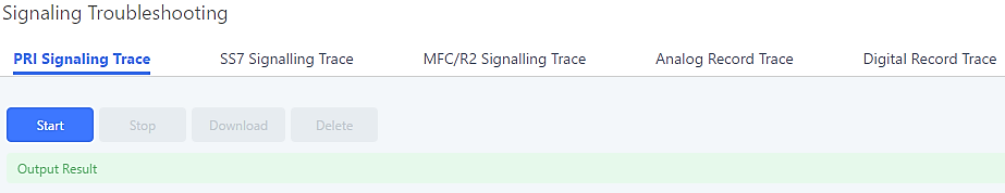
For E&M Immediate Signaling, user could configure “Record Direction” and “Record File Mode”.
After capturing a signaling trace, users can download it for analysis. Additionally, they can contact Grandstream Technical Support from the following link for further assistance: http://www.grandstream.com/support
Data Trunk
The UCM6510 E1/T1/J1 interface also supports data trunk function that allows users to access Internet. Users can select HDLC, HDLC-ETH, Cisco and PPP protocol for the data trunk.
To use data trunk,
- Go to Web GUI🡪PBX Settings🡪Interface Settings🡪Digital Hardware page and click to create a new group. Designate a channel for data trunk usage in the group setting.
- Go to Web GUI🡪Extension/Trunk🡪Data Trunks page, click on to edit the data trunk.
- Save the configuration and click on “Apply Changes” for the change to take effect.
- Once connected, the data trunk will periodically ping and check the status, with status indicator shown for the data trunk on the web page. The status indicator shows
 if connected successfully.
 - If the user happens to lose connection or experience unstable connection, click on
 to reconnect to help resolve the problem.
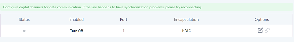
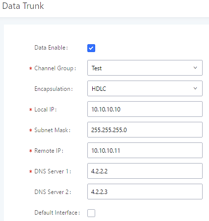
|
Data Enable |
Select the checkbox to enable/disable data trunk. Users can also click on the ON/OFF switch in data trunk web page to enable/disable this. |
|
Channel Group |
Select the digital channel group from the dropdown list to be used for data trunk. Users will need create a new group under Web GUI🡪PBX Settings🡪Interface Settings🡪Digital Hardware page for this purpose. |
|
Encapsulation |
Select the protocol used for the data trunk. The UCM6510 supports HDLC, HDLC-ETH, PPP, Cisco and Frame Relay. |
|
Local IP |
Configure the local IP address for the data port. This IP address should not conflict with the WAN or LAN side IP of the UCM6510. |
|
Subnet Mask |
Configure the subnet mask for the data port. |
|
Remote IP |
Configure the remote IP address for the data port. This IP will be the gateway IP address if “Default Interface” is enabled for the data trunk. |
|
DNS Server 1 |
Configure DNS server 1. |
|
DNS Server 2 |
Configure DNS server 2. |
|
Default Interface |
If enabled, this data port will be used as the default interface for Internet connection. The “Remote IP” will be the gateway IP address. This has higher priority than the “Default Interface” assignment (LAN 1 or LAN 2) under Web GUI🡪Settings if “Dual” is selected as the network method. |
VoIP Trunks
VoIP Trunk Configuration
VoIP trunks can be configured in UCM6510 under Web GUI🡪Extension/Trunk🡪VoIP Trunks. Once created, the VoIP trunks will be listed with Provider Name, Type, Hostname/IP, Username and Options to edit/detect the trunk.
- Click on “Create New SIP Trunk” or “Create New IAX Trunk” to add a new VoIP trunk.
- Click on to configure detailed parameters for the VoIP trunk.
- Click on to configure Direct Outward Dialing (DOD) for the SIP Trunk.
- Click on
 to start LDAP Sync.
 - Click on to delete the VoIP trunk.
The VoIP trunk options are listed in the table below.
|
Type |
Select the VoIP trunk type.
|
|
Configure a unique label (up to 64 characters) to identify this trunk when listed in outbound rules, inbound rules and etc. | |
|
Host Name |
Configure the IP address or URL for the VoIP provider’s server of the trunk. |
|
Keep Original CID |
Keep the CID from the inbound call when dialing out. This setting will override “Keep Trunk CID” option. Please ensure that the remote peer PBX supports matching user entry via the “username” field from authentication line. |
|
Keep Trunk CID |
If enabled, the trunk CID will not be overridden by extension’s CID when the extension has CID configured. The default setting is “No”. |
|
NAT |
Turn on this setting when the PBX is using public IP and communicating with devices behind NAT. If there is one-way audio issue, usually it is related to NAT configuration or SIP/RTP port support on the firewall. |
|
Disable This Trunk |
If checked, the trunk will be disabled. Note: If a current SIP trunk is disabled, UCM6510 will send UNREGISTER message (REGISTER message with expires=0) to the SIP provider. |
|
TEL URI |
If the trunk has an assigned PSTN telephone number, this field should be set to “User=Phone”. Then a “User=Phone” parameter will be attached to the Request-Line and TO header in the SIP request to indicate the E.164 number. If set to “Enable”, “Tel:” will be used instead of “SIP:” in the SIP request. The default setting is disabled. |
|
Caller ID |
Configure the Caller ID. This is the number that the trunk will try to use when making outbound calls. For some providers, it might not be possible to set the CallerID with this option and this option will be ignored. Important Note: When making outgoing calls, the following priority order rule will be used to determine which CallerID will be set before sending out the call :
|
|
Need Registration |
Select whether the trunk needs to register on the external server or not when “Register SIP Trunk” type is selected. The default setting is No. |
|
Username |
Enter the username to register to the trunk from the provider when “Register SIP Trunk” type is selected. |
|
Password |
Enter the password to register to the trunk from the provider when “Register SIP Trunk” is selected. |
|
Auth ID |
Enter the Authentication ID for “Register SIP Trunk” type. |
|
Auto Record |
Enable automatic recording for the calls using this trunk (for SIP trunk only). The default setting is disabled. The recording files can be accessed under Web GUI🡪CDR🡪Recording Files. |
|
Allows external numbers the option to get directed to the extension that last called them. For Example: User 2002 has dialed external number 061234575 but they were not reachable, once they have received missed call notification on their phone, they would mostly call back the number, if the option “Direct Callback” is enabled then they will be directly bridged to user 2002 regardless of the configured inbound destination. |
|
Basic Settings | |
|
Provider Name |
Configure a unique label to identify this trunk when listed in outbound rules, inbound rules and etc. |
|
Host Name |
Configure the IP address or URL for the VoIP provider’s server of the trunk. |
|
Transport |
Configure the SIP transport protocol to be used in this trunk. The default setting is “UDP”.
|
|
When TLS is selected as Transport for register trunk, users can select between SIP and SIPS URI scheme | |
|
Keep Original CID |
Keep the CID from the inbound call when dialing out. This setting will override “Keep Trunk CID” option. Please make sure that the peer PBX at the other side supports to match user entry using “username” field from authentication line. |
|
Keep Trunk CID |
If enabled, the trunk CID will not be overridden by extension’s CID when the extension has CID configured. The default setting is “No”. |
|
NAT |
Turn on this option when the PBX is using public IP and communicating with devices behind NAT. If there is one-way audio issue, usually it is related to NAT configuration or SIP/RTP port configuration on the firewall. |
|
Disable This Trunk |
If selected, the trunk will be disabled. Note: If a current SIP trunk is disabled, UCM6510 will send UNREGISTER message (REGISTER message with expires=0) to the SIP provider. |
|
TEL URI |
If the trunk has an assigned PSTN telephone number, this field should be set to “User=Phone”. Then a “User=Phone” parameter will be attached to the Request-Line and TO header in the SIP request to indicate the E.164 number. If set to “Enable”, “Tel:” will be used instead of “SIP:” in the SIP request. The default setting is disabled. |
|
Need Registration |
Select whether the trunk needs to register on the external server or not when “Register SIP Trunk” type is selected. The default setting is No. |
|
If enabled, outbound calls can still be made even if registration to the trunk fails. Note: If Need Registration is disabled, this option will be ignored. | |
|
CallerID Name |
Configure the new name of the caller when the extension has no CallerID Name configured. |
|
Configure the domain name of the SIP user account. This will overwrite the domain in the “From” header. Example: If the user account is “1234567”, setting “trunk.UCM6510.provider.com” as the From Domain value will result in the following From header: “sip:1234567@trunk.UCM6510.provider.com”. | |
|
From User |
Configure the username of the account. This will overwrite the user value in the From header. This is useful for scenarios where a single user account has multiple DIDs. Example: If the domain is “trunk.UCM6510.provider.com”, setting “1234567” as the From User value will result in the following From header: “sip. |
|
Username |
Enter the username to register to the trunk from the provider when “Register SIP Trunk” type is selected. |
|
Password |
Enter the password to register to the trunk from the provider when “Register SIP Trunk” is selected. |
|
Auth ID |
Enter the Authentication ID for “Register SIP Trunk” type. |
|
Auth Trunk |
If enabled, the UCM will send 401 response to the incoming call to authenticate the trunk. |
|
Auto Record |
Enable automatic recording for the calls using this trunk (for SIP trunk only). The default setting is disabled. The recording files can be accessed under Web GUI🡪CDR🡪Recording Files. |
|
Allows external numbers the option to get directed to the extension that last called them. For Example: User 2002 has dialed external number 061234575 but they were not reachable, once they have received missed call notification on their phone, they would mostly call back the number, if the option “Direct Callback” is enabled then they will be directly bridged to user 2002 regardless of the configured inbound destination. | |
|
Advanced Settings | |
|
Codec Preference | Select audio and video codec for the VoIP trunk. The available codecs are: PCMU, PCMA, GSM, AAL2-G.726-32, G.726, G.722, G.729, G.723, OPUS, ILBC, ADPCM, H.264, H.263, H.263p RTX, OPUS and VP8. |
|
Send PPI Header |
If enabled, the SIP INVITE message sent to the trunk will contain PPI (P-Preferred-Identity) header. The default setting is “No”. Note: “Send PPI Header” and “Send PAI Header” cannot be enabled at the same time. Only one of the two headers are allowed to be contained in the SIP INVITE message. |
| |
|
Send PAI Header |
If enabled, the SIP INVITE message sent to the trunk will contain PAI (P-Asserted-Identity) header including configured PAI Header. The default setting is “No”. Note: “Send PPI Header” and “Send PAI Header” cannot be enabled at the same time. Only one of the two headers are allowed to be contained in the SIP INVITE message. |
|
If “Send PAI Header” is enabled and “PAI Header” is configured as “123456” for instance, the PAI header in the SIP message sent from the UCM will contain “123456”. If “Send PAI Header” is enabled and “PAI Header” is configured as “empty”, the PAI header in the SIP message sent from the UCM will contain the original CID. Note: “Send PAI Header” needs to be enabled in order to use this feature. Only alphanumeric characters are allowed and/or special characters #*-_+. with a limit of 64 characters. | |
|
DOD As From Name |
If enabled and “From User” is configured, the INVITE’s From header will contain the DOD number. |
|
If checked and option “Send PAI Header” not checked, the PAI header will be passthrough from one side to the other side. | |
|
Outbound Proxy Support |
Select to enable outbound proxy in this trunk. The default setting is “No”. |
|
Outbound Proxy |
When outbound proxy support is enabled, enter the IP address or URL of the outbound proxy. |
|
DID Mode |
Configure where to get the destination ID of an incoming SIP call, from SIP Request-line or To-header. The default is set to “Request-line”. |
|
DTMF Mode |
Configure the default DTMF mode when sending DTMF on this trunk.
|
|
Enable Heartbeat Detection |
If enabled, the UCM6510 will regularly send SIP OPTIONS to the trunk to check connection status. The default setting is “No”. |
|
Heartbeat Frequency |
When “Enable Heartbeat Detection” option is set to “Yes”, configure the interval (in seconds) of the SIP OPTIONS message sent to the device to check if the device is still online. The default setting is 60 seconds. |
|
Maximum Number of Call Lines |
The maximum number of concurrent calls using the trunk. The default settings 0, which means no limit. |
|
Fax Mode |
Select Fax mode. The default setting is “None”.
|
|
SRTP |
Enable SRTP for the VoIP trunk. The default setting is “No”. |
|
Enable T.38 support for individual trunks. | |
|
CC Settings | |
|
Enable CC |
If enabled, the system will automatically alert the user when a called party is available, given that a previous call to that party failed for some reason. |
|
CC Max Agents |
Configure the maximum number of CCSS agents which may be allocated for this channel. In other words, this number serves as the maximum number of CC requests this channel is allowed to make. Minimum is 1. |
|
CC Max Monitors |
Configure the maximum number of monitor structures which may be created for this device. This number tells how many callers may request CC services for a specific device at one time. The minimum value is 1. |
|
Basic Settings | |
|
Provider Name |
Configure a unique label to identify this trunk when listed in outbound rules, inbound rules and etc. |
|
Host Name |
Configure the IP address or URL for the VoIP provider’s server of the trunk. |
|
Auto Record |
Enable automatic recording for the calls using this trunk (for SIP trunk only). The default setting is disabled. The recording files can be accessed under Web GUI🡪CDR🡪Recording Files. |
|
Keep Original CID |
Keep the CID from the inbound call when dialing out, this setting will override “Keep Trunk CID” option. Please ensure that the remote peer PBX supports matching user entry via the “username” field from authentication line. |
|
Keep Trunk CID |
If enabled, the trunk CID will not be overridden by extension’s CID when the extension has CID configured. The default setting is “No”. |
|
NAT |
Turn on this option when the PBX is using public IP and communicating with devices behind NAT. If there is one-way audio issue, usually it is related to NAT configuration or SIP/RTP port configuration on the firewall. |
|
Disable This Trunk |
If selected, the trunk will be disabled. Note: If a current SIP trunk is disabled, UCM6510 will send UNREGISTER message (REGISTER message with expires=0) to the SIP provider. |
|
TEL URI |
If the trunk has an assigned PSTN telephone number, this field should be set to “User=Phone”. Then a “User=Phone” parameter will be attached to the Request-Line and TO header in the SIP request to indicate the E.164 number. If set to “Enable”, “Tel:” will be used instead of “SIP:” in the SIP request. The default setting is disabled. |
|
Caller ID |
Configure the Caller ID. This is the number that the trunk will try to use when making outbound calls. For some providers, it might not be possible to set the CallerID with this option and this option will be ignored. Important Note: When making outgoing calls, the following priority order rule will be used to determine which CallerID will be set before sending out the call: CID from inbound call (Keep Original CID Enabled) 🡪 Trunk Username/CallerID (Keep Trunk CID Enabled) 🡪 DOD 🡪 Extension CallerID Number 🡪 Trunk Username/CallerID (Keep Trunk CID Disabled) 🡪 Global Outbound CID. |
|
CallerID Name |
Configure the name of the caller to be displayed when the extension has no CallerID Name configured. |
|
From Domain |
Configure the domain name of the SIP user account. This will overwrite the domain in the “From” header. Example: If the user account is “1234567”, setting “trunk.UCM6510.provider.com” as the From Domain value will result in the following From header: “sip:1234567@trunk.UCM6510.provider.com”.. |
|
Transport |
Configure the SIP transport protocol to be used in this trunk.
The default setting is “UDP”. |
|
Allows external numbers the option to get directed to the extension that last called them. For Example: User 2002 has dialed external number 061234575 but they were not reachable, once they have received missed call notification on their phone, they would mostly call back the number, if the option “Direct Callback” is enabled then they will be directly bridged to user 2002 regardless of the configured inbound destination. | |
|
Advanced Settings | |
|
Codec Preference | Select audio and video codec for the VoIP trunk. The available codecs are: PCMU, PCMA, GSM, AAL2-G.726-32, G.726, G.722, G.729, G.723, OPUS, ILBC, ADPCM, H.264, H.263, H.263p, RTX, OPUS and VP8. |
|
DID Mode |
Configure where to get the destination ID of an incoming SIP call, from SIP Request-line or To-header. The default is set to “Request-line”. |
|
DTMF Mode |
Configure the default DTMF mode when sending DTMF on this trunk.
|
|
Enable Heartbeat Detection |
If enabled, the UCM6510 will regularly send SIP OPTIONS to the trunk to check connection status. The default setting is “No”. |
|
Heartbeat Frequency |
When “Enable Heartbeat Detection” option is set to “Yes”, configure the interval (in seconds) of the SIP OPTIONS message sent to the device to check if the device is still online. The default setting is 60 seconds. |
|
Maximum Number of Call Lines |
The maximum number of concurrent calls using the trunk. The default settings 0, which means no limit. |
|
Fax Mode |
Select Fax mode. The default setting is “None”.
|
|
SRTP |
Enable SRTP for the VoIP trunk. The default setting is “No”. |
|
If enabled, it will allow SDP passthrough to Grandstream IPVideoTalk therefore it will allow calls between the UCM and IPVideoTalk. The default setting is disabled. | |
|
Sync LDAP Enable |
If enabled, the local UCM6510 will automatically provide and update the local LDAP contacts to the remote UCM6510 SIP peer trunk. In order to ensure successful synchronization, the remote UCM6510 peer also needs to enable this option on the SIP peer trunk. The default setting is “No”. |
|
Sync LDAP Password |
This is the password used for LDAP contact file encryption and decryption during the LDAP sync process. The password must be the same on both UCM6510 peers to ensure successful synchronization. |
|
Sync LDAP Port |
Configure TCP port used LDAP sync feature between two peer UCM6510. |
|
LDAP Outbound Rule |
Specify an outbound rule for LDAP sync feature. UCM6510 will automatically modify the remote contacts by adding prefix parsed from this rule. |
|
LDAP Dialed Prefix |
Specify the prefix for LDAP sync feature. The UCM6510 will automatically modify the remote contacts by adding this prefix. |
|
Enable T.38 UDPTL |
Enable T.38 support for individual trunks. |
|
CC Settings | |
|
Enable CC |
If enabled, the system will automatically alert the user when a called party is available, given that a previous call to that party failed for some reason. |
|
CC Max Agents |
Configure the maximum number of CCSS agents which may be allocated for this channel. In other words, this number serves as the maximum number of CC requests this channel is allowed to make. The minimum value is 1. |
|
CC Max Monitors |
Configure the maximum number of monitor structures which may be created for this device. In other words, this number tells how many callers may request CC services for a specific device at one time. Min. value is 1. |
|
Type |
Select the VoIP trunk type.
|
|
Provider Name |
Configure a unique label to identify this trunk when listed in outbound rules, inbound rules and etc. |
|
Host Name |
Configure the IP address or URL for the VoIP provider’s server of the trunk. |
|
Keep Trunk CID |
If enabled, the trunk CID will not be overridden by extension’s CID when the extension has CID configured. The default setting is “No”. |
|
Username |
Enter the username to register to the trunk from the provider when “Register IAX Trunk” type is selected. |
|
Password |
Enter the password to register to the trunk from the provider when “Register IAX Trunk” type is selected. |
|
Disable This Trunk |
If selected, the trunk will be disabled. |
|
Basic Settings | |
|
Provider Name |
Configure a unique label to identify this trunk when listed in outbound rules, inbound rules and etc. |
|
Host Name |
Configure the IP address or URL for the VoIP provider’s server of the trunk. |
|
Keep Trunk CID |
If enabled, the trunk CID will not be overridden by extension’s CID when the extension has CID configured. The default setting is “No”. |
|
Disable This Trunk |
If selected, the trunk will be disabled. |
|
Caller ID |
Configure the Caller ID. This is the number that the trunk will try to use when making outbound calls. For some providers, it might not be possible to set the CallerID with this option and this option will be ignored. Important Note: When making outgoing calls, the following priority order rule will be used to determine which CallerID will be set before sending out the call : From user (Register Trunk Only) 🡪 CID from inbound call (Keep Original CID Enabled) 🡪 Trunk Username/CallerID (Keep Trunk CID Enabled) 🡪 DOD 🡪 Extension CallerID Number 🡪 Trunk Username/CallerID (Keep Trunk CID Disabled) 🡪 Global Outbound CID. |
|
CallerID Name |
Configure the name of the caller to be displayed when the extension has no CallerID Name configured. |
|
Username |
Enter the username to register to the trunk from the provider. |
|
Password |
Enter the password to register to the trunk from the provider. |
|
Advanced Settings | |
|
Codec Preference | Select audio and video codec for the VoIP trunk. The available codecs are: PCMU, PCMA, GSM, AAL2-G.726-32, G.726, G.722, G.729, G.723, ILBC, ADPCM, H.264, H.263, H.263p. |
|
Enable Heartbeat Detection |
If enabled, the UCM6510 will regularly send SIP OPTIONS to the device to check if the device is still online. The default setting is “No”. |
|
Heartbeat Frequency |
When “Enable Heartbeat Detection” option is set to “Yes”, configure the interval (in seconds) of the SIP OPTIONS message sent to the device to check if the device is still online. The default setting is 60 seconds. |
|
Maximum Number of Call Lines |
The maximum number of concurrent calls using the trunk. The default settings 0, which means not limited. |
|
Fax Mode |
Select Fax mode. The default setting is “None”.
|
|
Basic Settings | |
|
Provider Name |
Configure a unique label to identify this trunk when listed in outbound rules, inbound rules and etc. |
|
Host Name |
Configure the IP address or URL for the VoIP provider’s server of the trunk. |
|
Keep Trunk CID |
If enabled, the trunk CID will not be overridden by extension’s CID when the extension has CID configured. The default setting is “No”. |
|
Disable This Trunk |
If selected, the trunk will be disabled. |
|
Caller ID |
Configure the Caller ID. This is the number that the trunk will try to use when making outbound calls. For some providers, it might not be possible to set the CallerID with this option and this option will be ignored. Important Note: When making outgoing calls, the following priority order rule will be used to determine which CallerID will be set before sending out the call : CID from inbound call (Keep Original CID Enabled) 🡪 Trunk Username/CallerID (Keep Trunk CID Enabled) 🡪 DOD 🡪 Extension CallerID Number 🡪 Trunk Username/CallerID (Keep Trunk CID Disabled) 🡪 Global Outbound CID. |
|
CallerID Name |
Configure the name of the caller to be displayed when the extension has no CallerID Name configured. |
|
Advanced Settings | |
|
Codec Preference | Select audio and video codec for the VoIP trunk. The available codecs are: PCMU, PCMA, GSM, AAL2-G.726-32, G.726, G.722, G.729, G.723, ILBC, ADPCM, H.264, H.263, H.263p. |
|
Enable Heartbeat Detection |
If enabled, the UCM6510 will regularly send SIP OPTIONS to the device to check if the device is still online. The default setting is “No”. |
|
Heartbeat Frequency |
When “Enable Heartbeat Detection” option is set to “Yes”, configure the interval (in seconds) of the SIP OPTIONS message sent to the device to check if the device is still online. The default setting is 60 seconds. |
|
Maximum Number of Call Lines |
The maximum number of concurrent calls using the trunk. The default settings 0, which means no limited. |
|
Fax Mode |
Select Fax mode. The default setting is “None”.
|
Trunk Groups
Users can create VoIP Trunk Groups to register and easily apply the same settings on multiple accounts within the same SIP server. This can drastically reduce the amount of time needed to manage accounts for the same server and improve the overall cleanliness of the web UI.
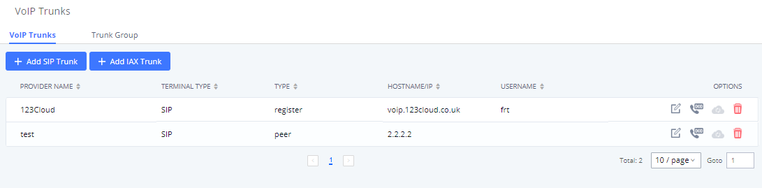
Once creating the new trunk group and configuring the SIP settings, users can add multiple accounts within the configured SIP server by pressing ![]() button and configuring the username, password and authentication ID fields.
button and configuring the username, password and authentication ID fields.
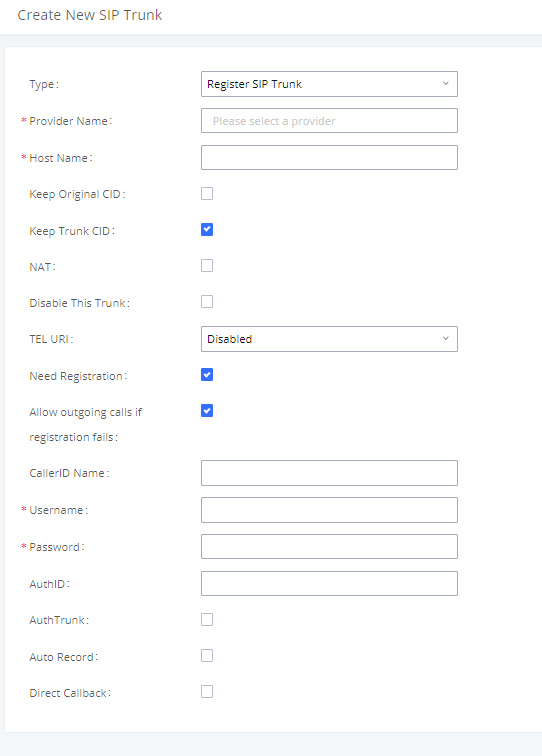
Direct Outward Dialing (DOD) via VoIP Trunks
The UCM6510 provides Direct Outward Dialing (DOD) which is a service of a local phone company (or local exchange carrier) that allows subscribers within a company’s PBX system to connect to outside lines directly.
Example of how DOD is used:
Company ABC has a SIP trunk. This SIP trunk has 4 DIDs associated to it. The main number of the office is routed to an auto attendant. The other three numbers are direct lines to specific users of the company. At the moment when a user makes an outbound call their caller ID shows up as the head office number. This poses a problem as the CEO would like their calls to come from their direct line. This can be accomplished by configuring DOD for the CEO’s extension.
Steps to configure DOD on the UCM:
- To setup DOD go to UCM6510 Web GUI🡪Extension/Trunk🡪VoIP Trunks page.
- Click
 to access the DOD options for the selected SIP Trunk.
 - Click “Create a new DOD” to begin your DOD setup.
- For “DOD Number” enter one of the numbers (DIDs) from your SIP trunk provider. In the example above Company ABC received 4 DIDs from their provider. ABC will enter the number for the CEO’s direct line.
- Set the DOD name If extension number need to be appended to the DID number click on “Add Extension”.
- Select an extension from the “Available Extensions” list. Users have the option of selecting more than one extension. In this case, Company ABC would select the CEO’s extension. After making the selection, click on the
 button to move the extension(s) to the “Selected Extensions” list.

- Click “Save” at the bottom.
Once completed, the user will return to the Edit DOD page that shows all the extensions that are associated to a particular DOD.
DOD can also be assigned to the UCM’s Fax Sending feature. To do this, select “VFAX” from the extension list when creating or editing a DOD number like shown below.
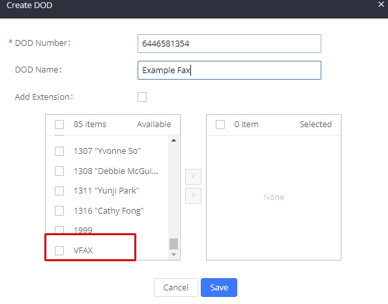
UCM6510 now supports to import/export DOD CSV file for an easy configuration.
- To Import DOD CSV file, click on “Import”.
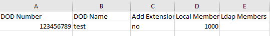
- To export the DOD file, users can click on “Export”.
SLA Station
UCM6510 supports SLA (Shared Line Appearance) that allows mapping the key with LED on a multi-line phone to different external lines. When there is an incoming call and the phone starts to ring, the LED on the key will flash in red and the call can be picked up by pressing this key. This allows users to know if the line is occupied or not. The SLA function on the UCM6510 is similar to BLF but SLA is used to monitor external line i.e., analog trunk on the UCM6510. Users could configure the phone with BLF mode on the MPK to monitor the analog trunk status or press the line key pick up call from the analog trunk on the UCM6510.
Create/Edit SLA Station
SLA Station can be configured on Web GUI🡪Extension/Trunk🡪SLA Station.
- Click on “Create New SLA Station” to add an SLA Station.
- Click on to edit the SLA Station. The following table shows the SLA Station parameters.
- Click on to delete the SLA Station.
|
|
Configure a name to identify the SLA Station. |
|
Station |
Specify a SIP extension as a station that will be using SLA. |
|
Available SLA Trunks |
Existing Analog Trunks with SLA Mode enabled will be listed here. |
|
Selected SLA Trunks |
Select a trunk for this SLA from the Available SLA Trunks list. Click on |
|
SLA Station Options | |
|
Ring Timeout |
Configure the time (in seconds) to ring the station before the call is considered unanswered. No timeout is set by default. If set to 0, there will be no timeout. |
|
Ring Delay |
Configure the time (in seconds) for delay before ringing the station when a call first coming in on the shared line. No delay is set by default. If set to 0, there will be no delay. |
|
Hold Access |
This option defines the competence of the hold action for one particular trunk. If set to “open”, any station could hold a call on that trunk or resume one held session; if set to “private”, only the station that places the trunk call on hold could resume the session. The default setting is “open”. |
Sample Configuration
- On the UCM6510, go to Web GUI 🡪 Extension/Trunk 🡪 Analog Trunks page. Create analog trunk or edit the existing analog trunk. Make sure “SLA Mode” is enabled for the analog trunk. Once enabled, this analog trunk will be only available for the SLA stations created under Web GUI 🡪 Extension/Trunk 🡪SLA Station page.
Click on “Save”. The analog trunk will be listed with trunk mode “SLA”.
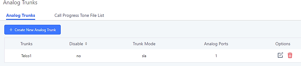
- On the UCM6510, go to Web GUI🡪Extension/Trunk🡪SLA Station page, click on “Create New SLA Station”. Please refer to section [Create/Edit SLA Station] for the configuration parameters. Users can create one or more SLA stations to monitor the analog trunk. The following figure shows two stations, 1002 and 1005, are configured to be associated with SLA trunk “fxo1”.

- On the SIP phone 1, configure to register UCM6510 extension 1002. Configure the MPK as BLF mode and the value must be set to “extension_trunkname”, which is 1002_fxo1 in this case.
- On the SIP phone 2, configure to register UCM6510 extension 1005. Configure the MPK as BLF mode and value must be set to “extension_trunkname”, which is 1005_fxo1 in this case.

Now the SLA station is ready to use. The following functions can be achieved by this configuration.
- Making an outbound call from the station/extension, using LINE key
When the extension is in an idle state, press the line key for this extension on the phone to off hook. Then dial the station’s extension number, for example, dial 1002 on phone 1 (or dial 1005 on phone 2), to hear the dial tone. Then the users could dial an external number for the outbound call.
- Making an outbound call from the station/extension, using BLF key
When the extension is in idle state, pressing the MPK and users could dial external numbers directly.
- Answering call using LINE key
When the station is ringing, pressing the LINE key to answer the incoming call.
- Barging-in active call using BLF key
When there is an active call between an SLA station and an external number using the SLA trunk, other SLA stations monitoring the same trunk could join the call by pressing the BLF key if “Barge Allowed” is enabled for the analog trunk.
- Hold/UnHold using BLF key
If the external line is previously put on hold by an SLA station, another station that monitors the same SLA trunk could UnHold the call by pressing the BLF key if “Hold Access” is set to “open” on the analog trunk and the SLA station.
Call Routes
Outbound Routes
Configuring Outbound Routes
In the UCM6510, an outgoing calling rule pairs an extension pattern with a trunk used to dial the pattern. This allows different patterns to be dialed through different trunks (e.g., “Local” 7-digit dials through an FXO while “Long distance” 10-digit dials through a low-cost SIP trunk). Users can also set up a failover trunk to be used when the primary trunk fails.
Go to Web GUI🡪Extension/Trunk🡪Outbound Routes to add and edit outbound rules.
- Click on “Create New Outbound Rule” to add a new outbound route.
- Click on to edit the outbound route.
- Click on to add a DOD to the outbound route
- Click on to delete the outbound route.
- On the UCM6510, the outbound route priority is based on “Best matching pattern”. For example, the UCM6510 has outbound route A with pattern 1xxx and outbound route B with pattern 10xx configured. When dialing 1000 for outbound call, outbound route B will always be used first. This is because pattern 10xx is a better match than pattern 1xxx. Only when there are multiple outbound routes with the same pattern configured, users can click on

 to move the outbound route up/down to arrange the priority among those outbound routes.
|
Calling Rule Name |
Configure the name of the calling rule (e.g., local, long_distance, and etc). Letters, digits, _ and – are allowed. |
X: Any Digit from 0-9. Z: Any Digit from 1-9. N: Any Digit from 2-9. “.“: Wildcard. Match one or more characters. “!“: Wildcard. Match zero or more characters immediately. Example: [12345–9] – Any digit from 1 to 9. Notes:
_X. _NNXXNXXXXX /* 10-digit long distance */ _818X. /* Any number with leading 818 */ | |
|
After creating the outbound route, users can choose to enable and disable it. If the route is disabled, it will not take effect anymore. However, the route settings will remain in UCM. Users can enable it again when it is needed. | |
|
Password |
Configure the password for users to use this rule when making outbound calls. |
|
Call Duration Limit |
Once call duration limit is enabled, it will set the maximum duration of call-blocking. |
|
Maximum Call Duration |
User can customize the maximum call duration (in seconds) that is allowed for the outbound call. By default, this value is set to 0 means there is no limit for the call duration. |
|
Warning Time |
This option will give caller warning when call duration is approaching to its limit. If the warning time is set to ‘y’, the warning tone will be played to caller when y seconds is left to end the call by UCM. |
|
Warning Repeat Interval |
Once this option is set to ‘z’, it will repeatedly be warning caller every z seconds after the first warning. |
|
PIN Groups |
If selected, the Password, Privilege Level and Enable Filter on Source Caller ID will not take effect. For more details, refer to [PIN Groups] section. |
|
If enabled and PIN Groups are used, Privilege Levels and Filter on Source Caller ID will also be applied. | |
|
Password |
Configure the password for users to use this rule when making outbound calls. |
|
Privilege Level |
Select privilege level for the outbound rule.
The lowest level required. All users can use this rule.
Users with Local, National, or International level are allowed to use this rule.
Users with National or International level are allowed to use this rule.
The highest level required. Only users with international level can use this rule. The default setting is “Disable”. Please be aware of the potential security risks when using “Internal” level, which means all users can use this outbound rule to dial out from the trunk. |
|
Enable Filter on Source Caller ID |
When enabled, users could specify extensions allowed to use this outbound route. “Privilege Level” is automatically disabled if using “Enable Filter on Source Caller ID”. The following two methods can be used at the same time to define the extensions as the source caller ID.
X: Any Digit from 0-9. Z: Any Digit from 1-9. N: Any Digit from 2-9. “.“: Wildcard. Match one or more characters. “!“: Wildcard. Match zero or more characters immediately. Example: [12345–9] – Any digit from 1 to 9. Note: Multiple patterns can be used. Patterns should be separated by comma “,”. Example: _X. , _NNXXNXXXXX , _818X. |
|
Attempt to use the configured outbound route CID. This CID will not be used if DOD is configured. It is formatted as “name<number>” or “<number>” or “number”. | |
|
Send This Call Through Trunk | |
|
Use Trunk |
Select the trunk for this outbound rule. |
|
Strip |
Allows the user to specify the number of digits that will be stripped from the beginning of the dialed string before the call is placed via the selected trunk. Example: The users will dial 9 as the first digit of a long-distance calls. However, 9 should not be sent out via analog lines and the PSTN line. In this case, 1 digit should be stripped before the call is placed. |
|
Prepend |
Specify the digits to be prepended before the call is placed via the trunk. Those digits will be prepended after the dialing number is stripped. |
|
Failover Trunk |
Failover trunks can be used to ensure calls can still be made in the scenario that the main trunk is congested or down. UCM6510 support up to 10 failover trunks. Example: The user’s primary trunk is a VoIP trunk and the user would like to use the PSTN when the VoIP trunk is not available. The PSTN trunk can be configured as the failover trunk of the VoIP trunk. |
|
Strip |
Allows the user to specify the number of digits that will be stripped from the beginning of the dialed string before the call is placed via the selected trunk. Example: The users will dial 9 as the first digit of a long-distance calls. However, 9 should not be sent out via analog lines and the PSTN line. In this case, 1 digit should be stripped before the call is placed. |
|
Prepend |
Specify the digits to be prepended before the call is placed via the trunk. Those digits will be prepended after the dialing number is stripped. |
|
Outbound routes can be configured to use different trunks based on time conditions such as holidays, office times, specific times, etc. |
Outbound Blacklist
The UCM6510 allows users to configure blacklist for outbound routes. If the dialing number matches the blacklist numbers or patterns, the outbound call will not be allowed. The outbound blacklist can be configured under UCM Web GUI🡪Extension/Trunk🡪Outbound Routes: Outbound Blacklist.
Users can configure number, pattern or select country code to add in the blacklist. Please note that the blacklist settings apply to all outbound routes.
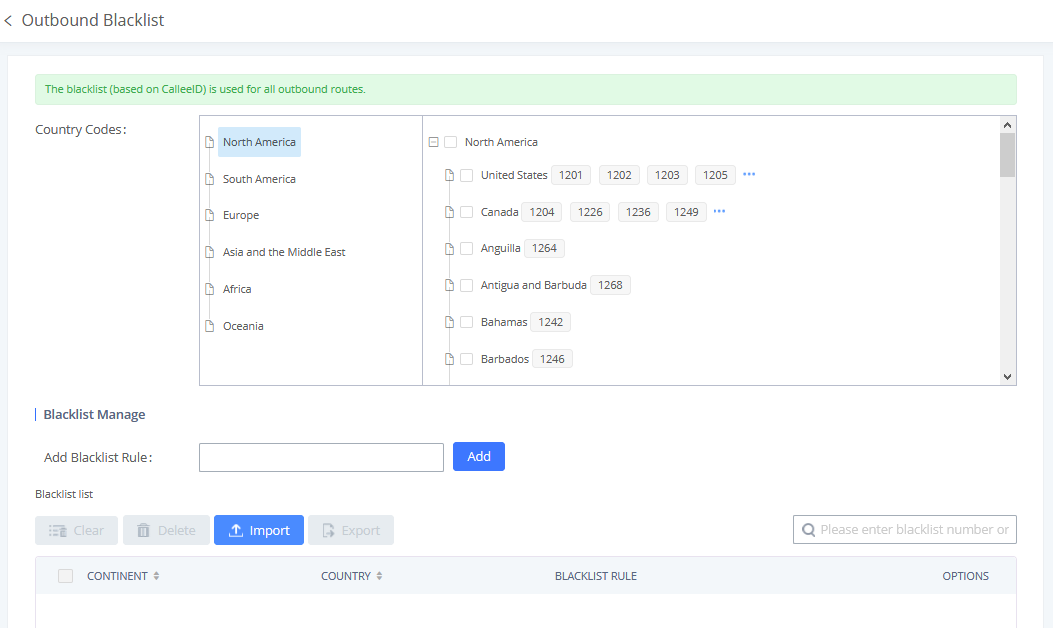
|
Blacklist Manage | |
|
Add Blacklist Rule |
Allows to define a rule based on number(s) or pattern(s) as blacklist entry. Pattern rules: N : Any digit from 2-9 X : Any digit from 0-9 Z : Any digit from 1-9 . : Wildcard, matching one or more characters ! : Wildcard, matching zero or more characters immediately – : Hyphens are used mainly to improve readability and are not involved in pattern matching. |
Users can export outbound route blacklists and delete all blacklist entries. Additionally, users can also import blacklists for outbound routes.
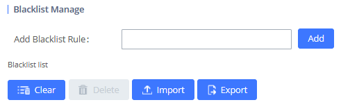
Scheduled Sync
Outbound Routes can be synced from a UTF-8 encoded CSV file located in the configured TFTP server. CSV files can be opened using programs such as Notepad and saved as a UTF-8 encoded file.
|
Sync Outbound Routes | |
|
Scheduled Sync |
Enable Scheduled Sync option. |
|
Server Address |
Enter the TFTP server address (e.g., 192.168.1.2:69). |
|
File Name |
Enter the file name. |
|
Sync Time |
Enter the sync time (24hr format). Valid range is 0-23. |
|
Sync Frequency |
Create new sync every x day(s). The valid range is 1 to 30. |
PIN Groups
The UCM6510 supports pin group. Once this feature is configured, users can apply pin group to specific outbound routes. When placing a call on pin protected outbound routes, caller will be asked to input the group pin number, this feature can be found on the webGUI🡪Extension/Trunk🡪Outbound Routes🡪PIN Groups.
|
Name |
Configure the name of the group |
|
Record In CDR |
Configure whether or not to display the used PIN group and name in a call’s CDR entry. |
|
PIN Number |
Configure the PIN that will be required to dial out. |
|
PIN Name |
Configure the name of the PIN |
Once user click on ![]() the following figure shows to configure the new PIN.
the following figure shows to configure the new PIN.
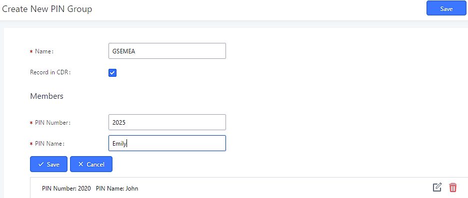
The following screenshot shows an example of created PIN Groups and members:
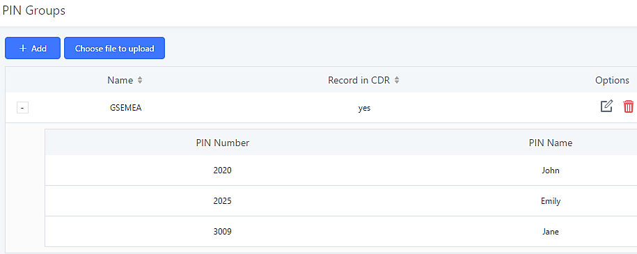
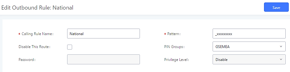
If PIN group CDR is enabled, the call with PIN group information will be displayed as part of CDR under Account Code field.
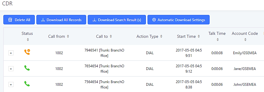
User can also import PIN Groups by uploading CSV files for each group. To do this:
- Navigate to Extension/Trunk🡪Outbound Routes🡪PIN Groups and click on the “Choose file to upload” button.

- Select the CSV file to upload. Incorrect file formats and improperly formatted CSV files will result in error messages such as the one below:
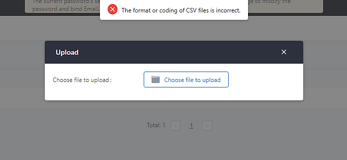
- To ensure a successful import, please follow the format in the sample image below
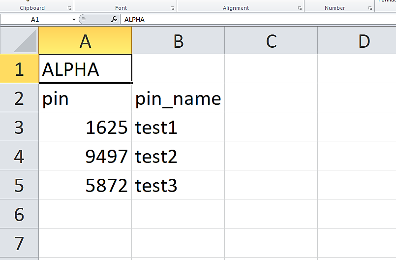
- The top-left value (A1) is the PIN Group name. In this case, it is “ALPHA”.
- Row 2 contains the labels for the modifiable fields: pin and pin_name. These values should not be changed and will cause an upload error otherwise.
- Rows 3+ contain the user-defined values with Column A holding the PINs and Column B holding the PIN names. PIN values must consist of at least four digits.
- Once the file is successfully uploaded, the entry will be added to the list of PIN Groups.
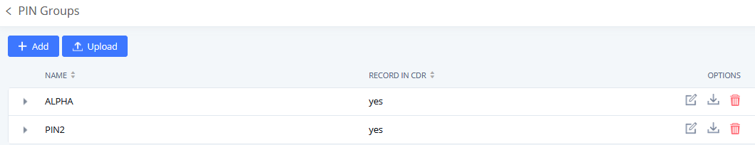
Press ![]() button under “Options” to download/export PIN Group settings.
button under “Options” to download/export PIN Group settings.
Inbound Routes
Inbound routes can be configured via Web GUI🡪Extension/Trunk🡪Inbound Routes.
- Click on “Create New Inbound Rule” button to add a new inbound route.
- Click on “Blacklist” button to configure blacklist for all inbound routes.
- Click on to edit the inbound route.
- Click on to delete the inbound route.
Inbound Rule Configurations
Trunks | Select the trunk to configure the inbound rule. |
Pattern | – All patterns are prefixed with the "_". – Special characters:
Example: [12345-9] - Any digit from 1 to 9. – There are two pattern fields: Pattern and CallerID:
Notes:
Example: |
Disable This Route | After creating the inbound route, users can choose to enable and disable it. |
Allowed to seamless transfer | Allows the selected extension to use this function. If an extension is busy, |
Alert-Info | Configure the Alert-Info, when UCM6510 receives an INVITE request, the |
Special Ringing Tone | This option will allow users to choose the custom ring back tone to play |
Fax Detection | If enabled, fax signals from the trunk during a call will be detected. |
Fax Destination | Configures the destination of faxes.
Note: Please make sure the sending email |
Prepend Trunk Name | If enabled, the trunk name will be added to the caller id name as the displayed caller id name. |
Block Collect Calls | If enabled, collect calls will be blocked. Note 1: Collect calls are indicated by the header “P-Asserted-Service-Info: service-code=Backward Collect Call, P-Asserted-Service-Info: service-code=Collect Call”. Note 2: There is also a global setting for this option in the SIP Settings -> General Settings page. |
Set Caller ID Info | Manipulates Caller ID (CID) name and/or number within the call flow to help identify who is calling. When enabled two field will show allowing to manipulate the CallerID Number and the Caller ID Name. |
CallerID Number | Configures the pattern-matching format to manipulate the numbers of incoming callers or to set a fixed CallerID number for calls that go through this inbound route.
|
CallerID Name | Default string is ${CALLERID(name)} which means the name of an incoming caller, it is a pattern-matching syntax format. A${CALLERID(name)}B means Prepend a character ‘A’ and suffix a character ‘B’ to ${CALLERID(name)}. Not using pattern-matching syntax means setting fix name to incoming caller. |
Enable Route-Level Inbound | Gives uses the ability to configure inbound mode per individual route. When enabled two fields will show allowing to set the Inbound mode and the Inbound mode Suffix. Note: Global inbound mode must be enabled before users can configure route-level inbound mode |
Inbound Mode | Choose the inbound mode for this route. Note: Toggling the global inbound mode will not affect routes that have Route-level Inbound Mode enabled. If all routes have the option enabled, toggling the global inbound mode via BLF will trigger a voice prompt indicating that none of the routes will be affected by the global inbound mode change. |
Inbound Mode Suffix | Dial “Global Inbound Mode feature code + Inbound Mode Suffix” or a route’s assigned suffix to toggle the route’s inbound mode. The BLF subscribed to the inbound mode suffix can monitor the current inbound mode. |
Inbound Multiple Mode | Multiple mode allows user to switch between destinations of the inbound rule by feature codes. Configure related feature codes as described in [Inbound Route: Multiple Mode]. If this option is enabled, user can use feature code to switch between different modes/destinations. |
Dial Trunk | This option shows up only when “By DID” is selected. If enabled, the external users dialing in to the trunk via this inbound route can dial outbound call using the UCM6510’s trunk. |
Privilege Level | This option shows up only when “By DID” is selected.
|
Allowed DID Destination | This option shows up only when “By DID” is selected. This controls the destination that can be reached by the external caller via the inbound route. The DID destination are:
|
Default Destination | Select the default destination for the inbound call.
When “By DID” is used, the UCM6510 will look for the destination based on the number dialed, which could be local extensions, conference, call queue, ring group, paging/intercom group, IVR, voicemail groups and Fax extension as configured in “DID destination”. If the dialed number matches the DID pattern, the call will be allowed to go through.
|
Strip | Specify the number of digits to strip from the beginning of the DID. This is used when “By DID” is selected in “Default Destination”. |
Prepend | Specify the digits to be prepended before the call is placed via the trunk. Those digits will be prepended after the dialing number is stripped. |
Time Condition | |
Start Time | Select the start time “hour:minute” for the trunk to use the inbound rule. |
End Time | Select the end time “hour:minute” for the trunk to use the inbound rule. |
Frequency | Select either “By Week” or “By Month” for the time condition. If “By Week” is selected, select the weekdays that the time condition will be used. |
Destination | Select the destination for the inbound call under the defined time condition.
When “By DID” is used, the UCM6510 will look for the destination based on the number dialed, which could be local extensions, conference, call queue, ring group, paging/intercom group, IVR, voicemail groups and Fax extension as configured in “DID destination”. If the dialed number matches the DID pattern, the call will be allowed to go through. Configure the number of digits to be stripped in “Strip” option.
|
Table 70: Outbound Routes/PIN Group
Inbound Route: Prepend Example
UCM6510 now allows user to prepend digits to an inbound DID pattern, with strip taking precedence over prepend. With the ability to prepend digits in inbound route DID pattern, user no longer needs to create multiple routes for the same trunk in order to route calls to different extensions.
The following example demonstrates the process:
- If Trunk provides a DID pattern of 18005251163.
- If Strip is set to 8, UCM6510 will strip the first 8 digits.
- If Prepend is set to 2, UCM6510 will then prepend a 2 to the stripped number, now the number become 2163.
- UCM6510 will now forward the incoming call to extension 2163.
Inbound Route: Multiple Mode
In UCM6510, user can configure inbound route to enable multiple mode to switch between different destinations. The inbound multiple mode can be enabled under Inbound Route settings.
When Multiple Mode is enabled for the inbound route, the user can configure a “Default Destination” and a “Mode 1” destination for all routes. By default, the call coming into this inbound route will be routed to the default destination.
SIP end devices that have registered on the UCM6510 can dial feature code *62 to switch to inbound route “Mode 1” and dial feature code *61 to switch back to “Default Destination”. Switching between different mode can be easily done without Web GUI login.
For example, the customer service hotline destination has to be set to a different IVR after 7PM. The user can dial *62 to switch to “Mode 1” with that IVR set as the destination before off work. To customize feature codes for “Default Mode” and “Mode 1”, click on ![]() under “Inbound Routes” page, check “Enable Inbound Multiple Mode” option and change “Inbound Default Mode” and “Inbound Mode 1” values (By default, *61 and *62 respectively).
under “Inbound Routes” page, check “Enable Inbound Multiple Mode” option and change “Inbound Default Mode” and “Inbound Mode 1” values (By default, *61 and *62 respectively).
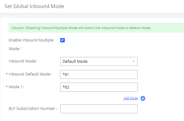
Inbound Route: Route-Level Mode
In the UCM6510, users can enable Route-Level Inbound Mode to switch between different destinations for each individual inbound route. The inbound Route-Level mode can be enabled under Inbound Route settings.
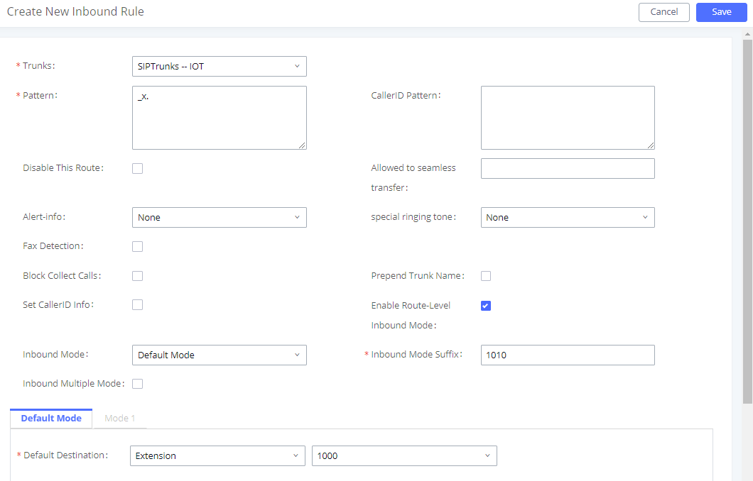
Figure 133: Inbound Route – Route-Level Mode
Global inbound mode must be enabled before configuring Route-Level Inbound Mode. Additionally, the Mode 1 must be configured as well.
When Route-Level Inbound Mode is enabled, the user can configure a “Default Destination” and a “Mode 1” destination for each specific route. By default, the call coming into this specific inbound route will be routed to the default destination.
Users can toggle the route’s inbound mode by dialing “Global Inbound Mode feature code + Inbound Mode Suffix” and the current inbound route can be monitored by subscribing a BLF to the Inbound Mode Suffix.
For example, Inbound Default Mode feature code is set to *61 and the Inbound Mode suffix for route 1 is set to 1010. To switch the mode of route 1 to Default Mode, users can dial *611010.
Inbound Route: Inbound Mode BLF Monitoring
Users can assign MPKs and VPKs to monitor and toggle the current global inbound mode of the UCM.
To do this, please refer to the following steps:
- Access the UCM web GUI and navigate to Extension/Trunk->Inbound Routes.
- Click on the
 button and enable Inbound Multiple Mode.
 - Edit the subscribe number field to the desired BLF value.
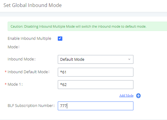
- Configure the BLF value on a phone’s MPK/VPK. As an example, a GXP2140 with the BLF configured will show the Inbound Mode status on its screen once configured. The 777 BLF is lit green, indicating that the current inbound mode is “Default Mode”.
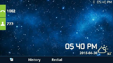
- Pressing the key will toggle the inbound mode to “Mode 1”, and the button’s color will change to red.
Inbound Route: Import/Export Inbound Route
Users can now import and export inbound routes to quickly set up inbound routing on a UCM or to back up an existing configuration. An exported inbound route configuration can be directly imported without needing any manual modifications.
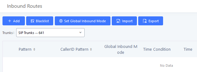
The imported file should be on CSV format and using UTF-8 encoding, the imported file should contain below columns, and each column should be separated by a comma (It is recommended to use Notepad++ for the imported file creation):
- Disable This Route: Yes/No.
- Pattern: Always prefixed with _
- CallerID Pattern: Always prefixed with _
- Prepend Trunk Name: Yes/No.
- Prepend User Defined Name Enable: Yes/No.
- Prepend User Defined Name: A string.
- Alert-info: None, Ring 1, Ring 2… User should enter an Alert-info string following the values we have in the Inbound route Alert-Info list.
- Allowed to seamless transfer: [Extension_number]
- Fax Detection: No, Yes.
- Fax Type: Extension, Fax to Email.
- Fax Destination: [Extension_number] or [Email address]
- Inbound Multiple Mode: Yes/No.
- Default Destination: By DID, Extension, Voicemail… User should enter a Default Destination string following the values we have in the Inbound route Default Destination list.
- Destination: An Extension number, Ring Group Extension…
- Default Time Condition.
- Mode 1: By DID, Extension, Voicemail… User should enter a Default Destination string following the values we have in the mode 1 Default Destination list.
- Mode 1 Destination: An Extension number, Ring Group Extension…
- Mode 1 Time Condition.
Fax with Two Media
Since UCM’s system is now based on Asterisk 13, fax re-invites that negotiate with multiple codecs are now supported. If a re-invite contains both T.38 and PCMU/PCMA codecs, T.38 will be prioritized.
In the UCM6510, Blacklist is supported for all inbound routes. Users could enable the Blacklist feature and manage the Blacklist by clicking on “Blacklist”.
- Select the checkbox for “Blacklist Enable” to turn on Blacklist feature for all inbound routes. Blacklist is disabled by default.
- Enter a number in “Add Blacklist Number” field and then click
 to add to the list. Anonymous can also be added as a Blacklist Number.
 - To remove a number from the Blacklist, select the number in “Blacklist list” and click on or click on
 button to remove all the numbers on the blacklist.
 - User can also export the inbound route blacklist by pressing on
 button.
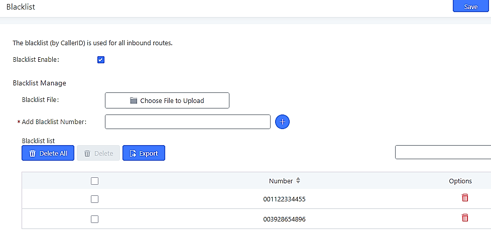
- To add blacklist number in batch, click on “choose file to upload” to upload blacklist file in csv format. The supported csv format is as below.
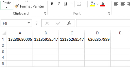
Conference
The UCM6510 supports Conference rooms allowing 64 participants with up to 8 bridged rooms at the same time. The conference room configurations can be accessed under Web GUI🡪Call Features🡪Conference.
In this page, users could create, edit, view, invite, manage the participants and delete conference rooms. The conference room status and conference call recordings (if recording is enabled) will be displayed in this web page as well.
Conference Room Configurations
- Click on “Create New Conference Room” to add a new conference room.
- Click on to edit the conference room.
- Click on to delete the conference room.
|
Configure the conference number for the users to dial into the conference. Note: The conference extension number can contain up to 64 characters. | |
|
When configured, the users who would like to join the conference call must enter this password before accessing the conference room. Notes:
| |
|
Host Password |
Configure the password to join the conference room as host. Conference host can manage the conference call via IVR (if “Enable Caller Menu” is enabled) as well as invite other parties to join the conference by dialing “0” (permission required from the invited party) or “1” (permission not required from the invited party) during the conference call. Notes: |
|
Enable Caller Menu |
If enabled, conference participant could press the * key to access the conference room menu. The default setting is “No”. |
|
Record Conference |
If enabled, the calls in this conference room will be recorded automatically in a .wav format file. All the recording files will be displayed and can be downloaded in the conference web page. The default setting is “No”. |
|
Quiet Mode |
If enabled, if there are users joining or leaving the conference, voice prompt or notification tone will not be played. The default setting is “No”. Note: “Quiet Mode” and “Announce Callers” cannot be enabled at the same time. |
|
If there is only one participant in a conference room, a kick warning prompt will play at the configured interval. If no input from the participant is received after the prompt, he will be automatically kicked out of the conference. The valid range is 1-60 minutes. | |
|
Wait For Host |
If enabled, the participants will not hear each other until the conference host joins the conference. The default setting is “No”. Note: If “Quiet Mode” is enabled, the voice prompt for “Wait For Host” will not be announced. |
|
Allow User Invite |
If enabled, users could press 0 to invite other users (with the users’ permission) or press 1 to invite other users (without the user’s permission) to join the conference. The default setting is “No”. Note: Conference host can always invite other users without enabling this option. |
|
If enabled, the caller will be announced to all conference participants when there the caller joins the conference. The default setting is “No”. Notes:
| |
|
Public Mode |
If enabled, no authentication will be required when joining the conference call. The default setting is “Yes”. |
|
Play Hold Music |
If enabled, the UCM6510 will play Hold music to the first participant in the conference until another user joins in. The default setting is “No”. |
|
Music On Hold |
Select the music on hold playlist to be played in conference call. This option shows up if “Play Hold Music For First Caller” is enabled. Music On Hold playlist can be set up under Web GUI🡪PBX Settings🡪Music On Hold. |
|
Custom Music On Hold |
Select a custom Music On Hold |
|
Skip Authentication |
If enabled, the invitation from Web GUI for a conference room with password will skip the authentication for the invited users. The default setting is “No”. |
Conference Settings contains the following options:
|
Enable Talk detection |
If enabled, the AMI will send the corresponding event when a user starts or ends talking. |
|
DSP Talking Threshold |
The time in milliseconds of sound above what the dsp has established as base line silence for a user before a user is considered to be talking. This value affects several operations and should not be changed unless the impact on call quality is fully understood, the default value is 128. |
|
DSP Silence Threshold |
The time in milliseconds of sound falling within the what the dsp has established as base line silence before a user is considered to be silent. This value affects several operations and should not be changed unless the impact on call quality is fully understood, the default value is 2500. |
|
Enable Neteq |
If enabled, conference audio quality may improve, but system performance will be lowered. |
Users can check the talking Caller IDs in conference control page (UCM WebUI🡪Call Features🡪Conference). The image will move up and down when the user is talking.
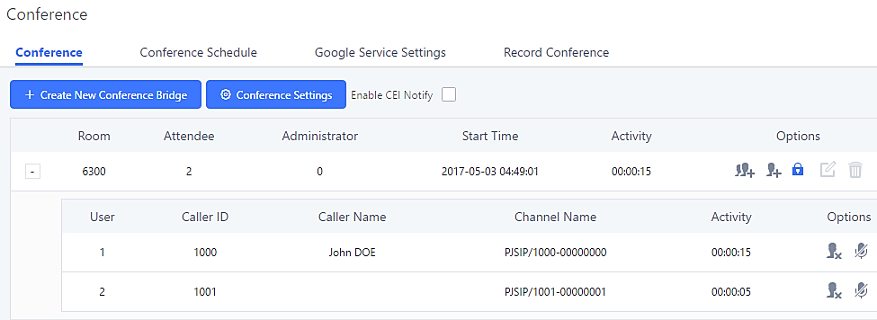
Conference Call Operations
Join a Conference Call
Users could dial the conference room extension to join the conference. If password is required, enter the password to join the conference as a normal user, or enter the admin password to join the conference as host.
Invite Other Parties to Join Conference
When using the UCM6510 conference room, there are two ways to invite other parties to join the conference.
- Invite from Web GUI
For each conference room in UCM6510 Web GUI🡪Call Features🡪Conference, there is an icon ![]() for option “Invite a participant”. Click on it and enter the number of the party you would like to invite. Then click on “Add”. A call will be sent to this number to invite it to the conference.
for option “Invite a participant”. Click on it and enter the number of the party you would like to invite. Then click on “Add”. A call will be sent to this number to invite it to the conference.
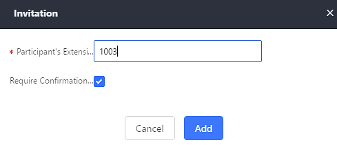
- Invite by dialing 0 or 1 during conference call
A conference participant can invite other parties to the conference by dialing during the conference call. Please make sure “Allow User Invite” is turned on for the conference room first. Enter 0 or 1 during the conference call. Follow the voice prompt to input the number of the party you would like to invite. A call will be sent to this number to join it into the conference.
If 0 is entered, once the invited party picks up the invitation call, the system will ask the party to accept or reject the invitation.
If 1 is entered, once the invited party picks up the call, they will automatically be brought into the conference.
During The Conference
During the conference call, users can manage the conference from Web GUI or IVR.
- Manage the conference call from Web GUI.
![]() Log in UCM6510 Web GUI during the conference call, the participants in each conference room will be listed.
Log in UCM6510 Web GUI during the conference call, the participants in each conference room will be listed.
- Click on to kick a participant from the conference.
 Click on to mute the participant.
 Click on to lock this conference room so that other users cannot join it anymore.
 Click on to invite other users into the conference room.
- Manage the conference call from IVR.
If “Enable Caller Menu” is enabled, conference participant can input * to enter the IVR menu for the conference. Please see options listed in the table below.
|
Conference Administrator IVR Menu | |
|
1 |
Mute/unmute yourself. |
|
2 |
Lock/unlock the conference room. |
|
3 |
Kick the last joined user from the conference. |
|
4 |
Decrease the volume of the conference call. |
|
6 |
Increase the volume of the conference call. |
|
7 |
Decrease your volume. |
|
9 |
Increase your volume. |
|
8 |
More options:
|
|
Conference User IVR Menu | |
|
1 |
Mute/unmute yourself. |
|
4 |
Decrease the volume of the conference call. |
|
6 |
Increase the volume of the conference call. |
|
7 |
Decrease your volume. |
|
9 |
Increase your volume. |
|
8 |
Exit the caller menu and return to the conference. |
Google Service Settings Support
UCM6510 now supports Google OAuth 2.0 authentication. This feature is used for supporting UCM6510 conference scheduling system. Once OAuth 2.0 is enabled, UCM6510 conference system can access Google calendar to schedule or update conference.
Google Service Settings can be found under Web GUI🡪Call Features🡪Conference🡪Google Service Settings.
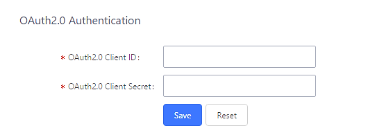
If you already have OAuth2.0 project set up on Google Developers web page, please use your existing login credential for “OAuth2.0 Client ID” and “OAuth2.0 Client Secret” in the above figure for the UCM6510 to access Google Service.
If you do not have OAuth2.0 project set up yet, please following the steps below to create new project and obtain credentials:
- Go to Google Developers page https://console.developers.google.com/start Create a New Project in Google Developers page.
- Enable Calendar API from API Library.
- Click “Credentials” on the left drop down menu to create new OAuth2.0 login credentials.
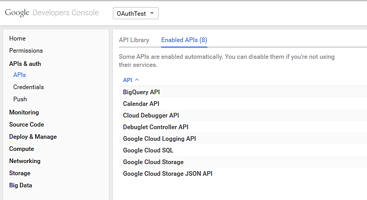
- Use the newly created login credential to fill in “OAuth2.0 Client ID” and “OAuth2.0 Client Secret”.
- Click “Get Authentication Code” to obtain authentication code from Google Service.
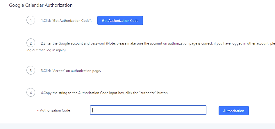
- Now UCM6510 is connected with Google Service.
Conference Schedule
Conference Schedule can be found under UCM6510 Web GUI🡪Call Features🡪Conference Schedule. Users can create, edit, view and delete a Conference Schedule.
- Click on “Create New Conference Schedule” to add a new Conference Schedule.
- Click on the scheduled conference to edit or delete the event.
After the user configures UCM6510 with Google Service Settings [Google Service Settings Support] and enables Google Calendar for Conference Schedule, the conference schedule on the UCM6510 can be synchronized with Google Calendar for authorized Google account.
|
Schedule Options | |
|
Conference Subject |
Configure the topic of the scheduled conference. Letters, digits, _ and – are allowed. |
|
Conference Room |
Select a conference room for this scheduled conference. |
|
Conference Password |
Conference login password. |
|
Host Password |
Host Password. |
|
Kick Time(m) |
Set kick time before conference starts. When kick time is reached, a warning prompt will be played for all attendees in the conference room. After 5 minutes, this conference room will be cleared and locked for the scheduled conference to begin. Note: Kick Time cannot be less than 6 minutes in order to clear the conference room. |
|
Wait for Host |
If enabled, conference participants will not hear each other until the host joins the conference. |
|
Description |
The description of scheduled conference. |
|
Repeat |
Repeat interval of scheduled conference. By default, set to single event. |
|
Schedule Time |
Configure the beginning date and duration of scheduled conference. Note: Please pay attention to avoid time conflict on schedules in the same conference room. |
|
Duration of the conference meeting. Note: The maximum allowed meeting duration that can be set is 8 hour(s). | |
|
Enable Google Calendar |
Select this option to synchronize scheduled conference with Google Calendar. Note: Google Service Setting OAuth2.0 must be configured on the UCM6510. Please refer to section [Google Service Settings Support]. |
|
Send email notification |
Sends Email notification to the extension. |
|
Conference Administrator |
Select the administrator of scheduled conference from selected extensions. Note: “Public Mode” must be disabled from Conference Room Options tab. |
|
Local Extension |
Select available extensions from the list to attend scheduled conference. |
|
Remote Extension |
Select available extensions from the remote peer PBX. Note: “LDAP Sync” must be enabled on the UCM6510 in order to view remote extensions here. |
|
Special Extension |
Add extensions that are not in the list (both local and remote list). If the user wishes to add the special extension, please make sure that the UCM’s outbound routes will allow calling that special extension. |
|
Remote Conference |
Invite a remote conference. |
|
Conference Room Options | |
|
Password |
Configure conference room password. Please note that if “Public Mode” is enabled, this option is automatically disabled. |
|
Admin Password |
Configure the password to join as conference administrator. Please note that if “Public Mode” is enabled, this option is automatically disabled. |
|
Enable Caller Menu |
If this option is enabled, conference participants will be able to access conference room menu by pressing the * key. |
|
Record Conference |
If this option is enabled, conference call will be recorded in .wav format. The recorded file can be found from Conference page. |
|
Quiet Mode |
If this option is enabled, the notification tone or voice prompt for joining or leaving the conference will not be played. Note: Option “Quiet Mode” and option “Announce Caller” cannot be enabled at the same time. |
|
Wait For Admin |
If this option is enabled, the participants in the conference will not be able to hear each other until conference administrator joins the conference. Note: If “Quiet Mode” is enabled, voice prompt for this option will not be played. |
|
Enable User Invite |
If this option is enabled, the user can:
Note: Conference Administrator is always allowed to access this menu. |
|
Announce Callers |
If this option is enabled, when a participant joins the conference room, participant’s name will be announced to all members in the conference room. Note: Option “Quiet Mode” and option “Announce Caller” cannot be enabled at the same time. |
|
Public Mode |
If this option is enabled, no authentication is required for entering the conference room. Note: Please be aware of the potential security risks when turning on this option. |
|
Play Hold Music |
If this option is enabled, UCM6510 will play Hold Music while there is only one participant in the conference room or the conference is not yet started. |
|
Skip Authentication When Inviting Users via Trunk from Web GUI |
If this option is enabled, the invitation from Web GUI via a trunk with password will not require authentication. Note: Please be aware of the potential security risks when turning on this option. |
Cleaner Options
|
Cleaner Options | |
|
Enable Conference Schedules Cleaner |
If this option is enabled, conference schedules will be automatically cleaned as configured. |
|
Conference Schedules Clean Time |
Enter the clean time (in hours). The valid range is from 0 to 23. |
|
Clean Interval |
Enter the clean interval (in days). The valid range is from 1 to 30. |
After configuring the scheduled conference, it will be shown under Conference Schedule page as below:

Once the conference room is scheduled, at the kick time, all users will be removed from conference room and no extension is allowed to join the conference room anymore. At the scheduled conference time, UCM6510 will send INVITE to the extensions that have been selected for conference.
Contact Group
Users can quickly invite multiple participants at once to a conference via conference contact groups. Up to 5 contact groups can be created. The maximum allowed number of contacts per group is based on the UCM model’s conference participant limit: 25 for 6202/6204, 32 for 6208, 64 for 6510.
Each contact group must have a password configured, which will be required when inviting the specified contact group to a conference. Additionally, an audio file can be uploaded to each group to be used to announce the contact group name such as “Sales” or “Marketing”. The default announcement for each group is “Conference Contact Group 1”, “Conference Contact Group 2”, etc.
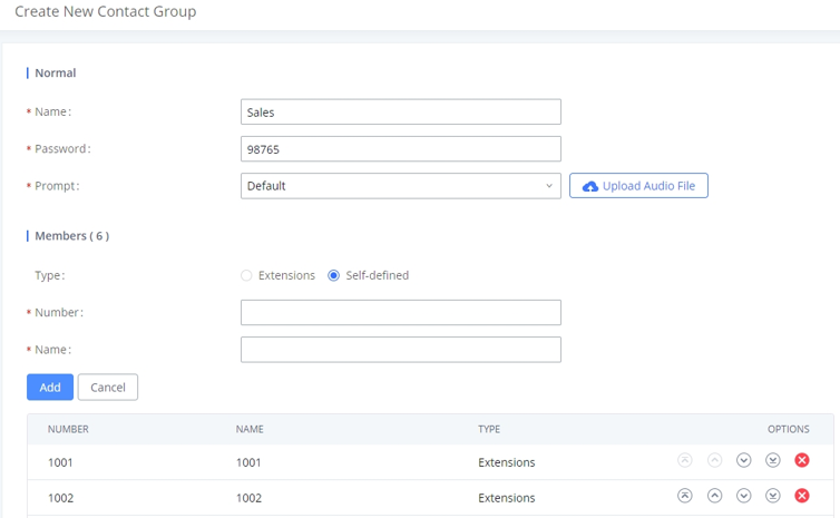
Contact Group Configurations
- Click on “Create New Contact Group” to add a new Contact Group.
- Click on to edit the Contact Group.
- Click on to delete the Contact Group.
|
Name |
Name associated to the contact group. |
|
Password |
Password required to invite the specified contact group to a conference. |
|
Prompt |
Audio file that can be uploaded to the group to announce the contact group name such as “Sales” or “Marketing”. The default announcement for each group is “Conference Contact Group 1”, “Conference Contact Group 2”, etc. |
|
Members |
Contacts that needs to be added in each group. |
|
Type |
Type of the members to be added, it can be either Extensions or a self-defined number. |
Conference Recordings
The UCM6510 allows users to record the conference call and retrieve the recording from Web GUI🡪Call Features🡪Conference.
To record the conference call, when the conference room is in idle, enable “Record Conference” from the conference room configuration dialog. Save the setting and apply the change. When the conference call starts, the call will be automatically recorded in .wav format.
The recording files will be listed as below once available. Users could click on ![]() to download the recording or click on
to download the recording or click on ![]() to delete the recording.
to delete the recording.
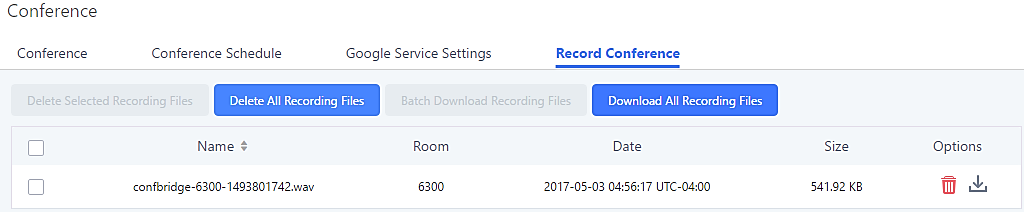
Conference Call Statistics
Conference reports will now be generated after every conference. These reports can be exported to a .CSV file for offline viewing. The conference report page can be accessed by clicking on the Call Statistics button on the main Conference page.
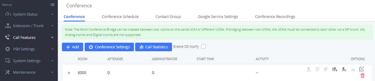
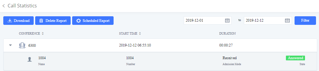
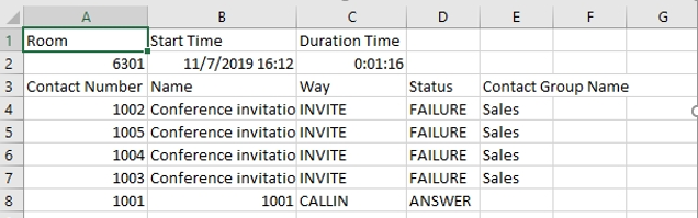
Video Conference
With the UCM you can easily create, schedule, manage, and join video conference calls, from your desktop or laptop computer. UCM Video conferencing uses WebRTC technology, so all the participants don’t have to download and install any additional software or plugins. If upgrading from firmware that does not have this functionality, system administrators must first toggle on the Enable WebRTC option for extensions that want to use the UCM’s WebRTC video conferencing feature. The video conference configurations can be accessed under Web GUI🡪Call Features🡪Video Conference. Here, users can create and manage video conference rooms and schedule video conferences.
Video Conference Room Configurations
- Click on “Create New Conference Room” to add a new conference room.
- Click on to edit the conference room.
- Click on to delete the conference room.
|
Extension |
Configure the conference number for the users to dial into the conference. Note: Up to 64 characters. |
|
Password |
When configured, the users who would like to join the conference call must enter this password before accessing the conference room. Note:
|
Conference Settings
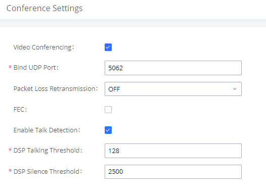
|
Basic Settings | |
|
Video Conferencing |
This option should be enabled in order to activate the Video Conference feature. |
|
Bind UDP Port |
Configure the UDP port number for MCM. The standard UDP port for MCM is 5062. |
|
Packet Loss Retransmission |
Configure to enable Packet Loss Retransmission. |
|
FEC |
If enabled, the Forward Error Correction (FEC) will be activated. The default setting is “No”. |
|
Enable Talk Detection |
If enabled, the AMI will send the corresponding event when a user starts or stops talking. |
|
DSP Talking Threshold |
The amount of time (ms) that sound exceeds what the DSP has established as the baseline for silence before a user is considered to be talking. This value affects several operations and should not be changed unless the impact on call quality is fully understood. |
|
DSP Silence Threshold |
The amount of time(ms) that sound falls within what the DSP has established as the baseline for silence before a user is considered be silent. This value affects several operations and should not be changed unless the impact on call quality is fully understood. |
Conference Schedule
Conference Schedule can be found under UCM6510 Web GUI 🡪 Call Features🡪Video Conference 🡪 Conference Schedule. Users can create, edit, view and delete a Conference Schedule.
- Click on “Schedule New Conference” to add a new Conference Schedule.
- Click on the scheduled conference to edit or delete the event.
|
Schedule Options | |
|
Conference Subject |
Configure the topic of the scheduled conference. Letters, digits, _ and – are allowed. |
|
Conference Room |
Select a conference room for this scheduled conference. |
|
Conference Password |
Configure conference room password. Please note that if “Public Mode” is enabled, this option is automatically disabled. |
|
Kick Time(m) |
Configure the time before the scheduled conference. When this time is reached, a warning prompt will be played, and all attendees currently in the scheduled conference room will be kicked after 5 mins. The conference room will be locked until the scheduled conference begins. Default value is 10 min. |
|
Schedule Time |
Configure the beginning date and duration of scheduled conference. Note: Please be mindful to avoid schedule conflicts for the same conference room. |
|
Host |
Set the admin of this scheduled conference from the following list of members. |
|
Members |
Select available extensions from the list to attend scheduled conference. |
|
Special Extension |
Add extensions that are not in the list (both local and remote list). If the user wishes to add the special extension, please make sure that the UCM’s outbound routes will allow calling that special extension. |
|
Description |
Set a description of scheduled conference. |
|
Time Zone |
Configure the conference Time Zone. |
|
Local Extension |
Select the extensions from the list to attend this scheduled conference. |
|
Remote Extension |
The remote extension in the peer PBX connected to the local PBX via LDAP sync. |
Once created, the Web GUI will display scheduled conference in Conference Schedule. Please see figure below:
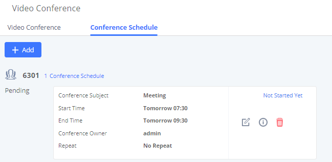
Once the conference room is scheduled, at the kick time, all users will be removed from conference room and no extension is allowed to join the conference room anymore. At the scheduled conference time, UCM6510 will send INVITE to the extensions that have been selected for conference.
Wave WebRTC Video Calling & Conferencing
Web audio and video calls and conferencing can now be achieved through the UCM’s new WebRTC page. To get started with this new feature, please make sure to:
- Navigate to Value-Added Features 🡪 WebRTC and enable WebRTC support.
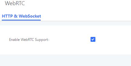
- Enable the WebRTC on the extensions that would use this feature under Extension / Trunk 🡪 Extensions.
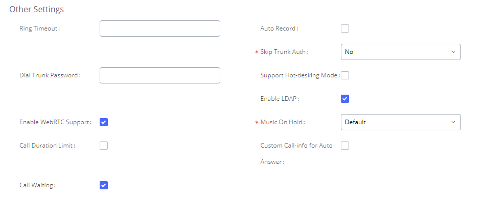
The UCM offers the possibility to log in to an extension via Grandstream Wave Portal using user portal password in addition to SIP registration password, where it offers a sleek interface to host conferences, receive email reminders for scheduled conferences, manage contacts, initiate calls, call transfer, chat functionality and more.
Access the page by adding “/gswave” after the UCM’s server address and port. (e.g. https://my.ucm.com:8089/gswave).

For more details about the WebRTC feature, please refer to the following guide:
https://documentation.grandstream.com/knowledge-base/wave-video-calling-conferencing-guide/
IPVideoTalk Meetings
UCM extensions can now dial into IPVT (IPVideoTalk) meetings by creating a peer trunk to an IPVT server. However, users must make sure that the IPVT server they are peering to also has a peer trunk to their UCM configured. This setting can be found in Admin Center🡪SIP Trunk Configuration.
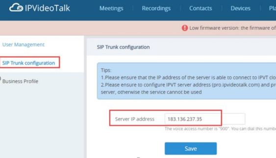
Next, users must create a peer trunk on the UCM to the IPVT server. Enter one of the following addresses based on the desired connection protocol:
- TCP: pro.ipvideotalk.com:20000
- TLS: pro.ipvideotalk.com:20001
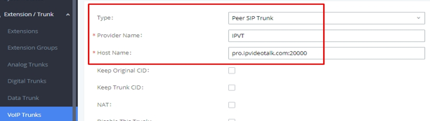
Make sure that the Transport field is either “TCP” or “TLS”. Save and apply changes to create the trunk.
Next, edit the newly created trunk and click on the Advanced Settings tab. Make sure the IPVT Mode option is checked. Otherwise, you may experience audio issues when dialing into IPVT.
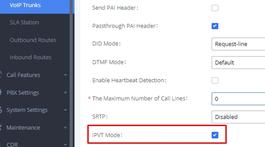
Finally, create an outbound route for this trunk. This route will be used to dial IPVT meeting IDs. Due to IPVT meeting IDs having a random assortment of numbers, it is recommended to use a unique code to precede the meeting ID so that UCM can direct calls to the IPVT trunk without fail (e.g., *99). In the below image, “x.” would be the meeting ID.
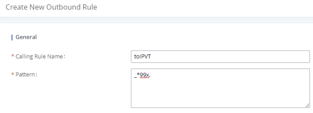
However, if a unique code is used, users must also configure the Strip field to remove the unique code from the meeting ID before the call is sent to IPVT.
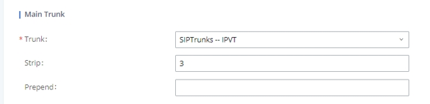
In this example, the Strip field has “3” configured to remove the example unique code *99 from the dialed number before the call is routed out to the IPVT server. Once this outbound route has been created, users can now use a UCM extension to dial IPVT meeting rooms.
IVR
Configure IVR
IVR configurations can be accessed under the UCM6510 Web GUI🡪Call Features🡪IVR. Users could create, edit, view and delete an IVR.
- Click on “Create New IVR” to add a new IVR.
- Click on to edit the IVR configuration.
- Click on to delete the IVR.
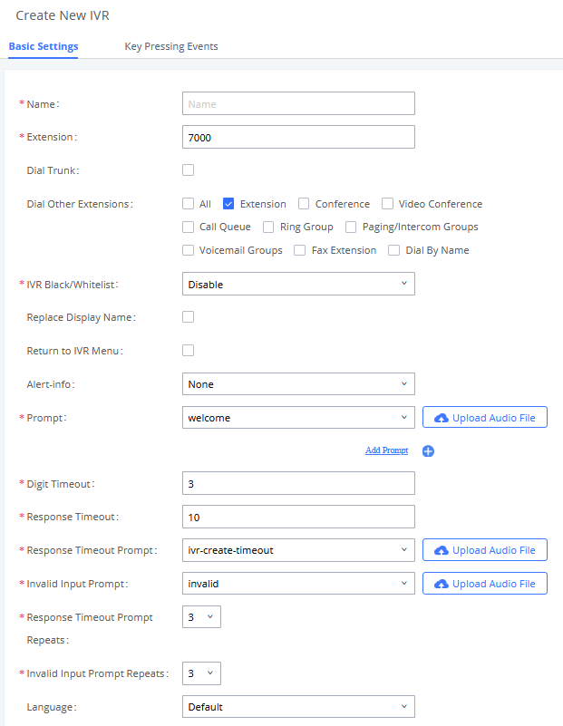
|
Basic Settings | |
|
Name |
Configure the name of the IVR. Letters, digits, _ and – are allowed. |
|
Extension |
Enter the extension number for users to access the IVR. |
|
Dial other Extensions |
If enabled, the caller is allowed to dial extensions other than the ones explicitly defined. |
|
DID Destination |
This option shows up only when “By DID” is selected. This controls the destination that can be reached by the external caller via the inbound route. The DID destination are:
|
|
Dial Trunk |
If enabled, all callers to the IVR is allowed to use trunk. The permission must be configured for the users to use the trunk first. The default setting is “No”. |
|
Permission |
Assign permission level for outbound calls if “Dial Trunk” is enabled. The available permissions are “Internal”, “Local”, “National” and “International” from the lowest level to the highest level. The default setting is “Internal”. If the user tries to dial outbound calls after dialing into the IVR, the UCM6510 will compared the IVR’s permission level with the outbound route’s privilege level. If the IVR’s permission level is higher than (or equal to) the outbound route’s privilege level, the call will be allowed to go through. |
|
If enabled, the UCM will replace the caller display name with the IVR name the caller know whether the call is incoming from a direct extension or an IVR. | |
|
Alert-Info |
When present in an INVITE request, the alert-Info header field specifies and alternative ring tone to the UAS. |
|
Return to IVR Menu |
If enabled and if a call to an extension fails, the caller will be redirected to the IVR menu. |
| Select an audio file to play as the welcome prompt for the IVR. Click on “Prompt” to add additional audio file under Web GUI🡪PBX Settings🡪Voice Prompt🡪Custom Prompt. Note: Up to 5 welcome prompts can be used. | |
|
Digit Timeout |
Configure the timeout between digit entries. After the user enters a digit, the user needs to enter the next digit within the timeout. If no digit is detected within the timeout, the UCM6510 will consider the entries complete. The default timeout is 3 seconds. |
|
Response Timeout |
After playing the prompts in the IVR, the UCM6510 will wait for the DTMF entry within the timeout (in seconds). If no DTMF entry is detected within the timeout, a timeout prompt will be played. The default setting is 10 seconds. |
|
Response Timeout Prompt |
Select the prompt message to be played when timeout occurs. |
|
Invalid Prompt |
Select the prompt message to be played when an invalid extension is pressed. |
|
Response Timeout Prompt Repeats |
Configure the number of times to repeat the prompt if no DTMF input is detected. When the loop ends, it will go to the timeout destination if configured, or hang up. The default setting is 3. |
|
Invalid Input Prompt Repeats |
Configure the number of times to repeat the prompt if the DTMF input is invalid. When the loop ends, it will go to the invalid destination if configured, or hang up. The default setting is 3. |
|
Language |
Select the voice prompt language to be used for this IVR. The default setting is “Default” which is the selected voice prompt language under Web GUI🡪PBX Settings🡪Voice Prompt🡪Language Settings. The dropdown list shows all the current available voice prompt languages on the UCM6510. To add more languages in the list, please download voice prompt package by selecting “Check Prompt List” under Web GUI🡪PBX Settings🡪Voice Prompt🡪Language Settings. |
|
Key Pressing Events | |
|
Key Press Event: Press 0 Press 1 Press 2 Press 3 Press 4 Press 5 Press 6 Press 7 Press 8 Press 9 Press * Timeout Invalid |
Select the event for each key pressing for 0-9, *, Timeout and Invalid. The event options are:
|
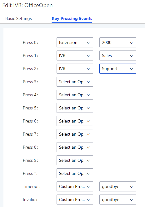
IVR Black/Whitelist
In some scenarios, the IPPBX administrator needs to restrict the extensions that can be reached from IVR.
For example, the company CEO and directors prefer only receiving calls transferred by the secretary, some special extensions are used on IP surveillance end points which shouldn’t be reached from external calls via IVR for privacy reason. UCM has now added blacklist and whitelist in IVR settings for users to manage this.
To use this feature, log in UCM Web GUI and navigate to Call Features🡪IVR🡪Create/Edit IVR: IVR
Black/Whitelist.
- If the user selects “Blacklist Enable” and adds extension in the list, the extensions in the list will not be allowed to be reached via IVR.
- If the user selects “Whitelist Enable” and adds extension in the list, only the extensions in the list can be allowed to be reached via IVR.
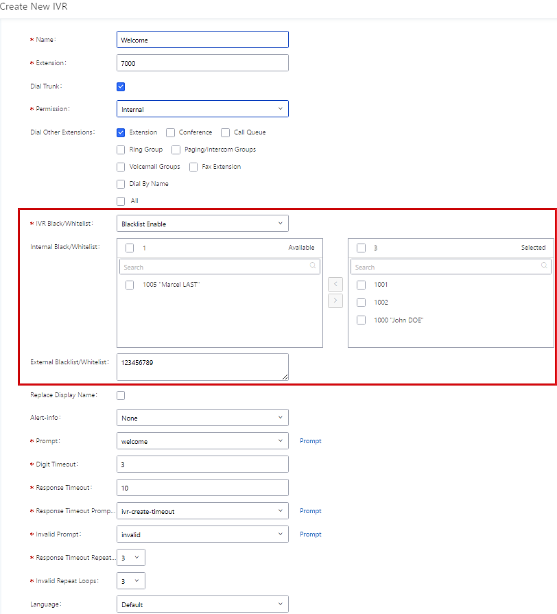
Create Custom Prompt
To record new IVR prompt or upload IVR prompt to be used in IVR, click on “Prompt” next to the “Welcome Prompt” option and the users will be redirected to IVR Prompt page. Or users could go to Web GUI🡪PBX Settings🡪Voice Prompt🡪Custom Prompt page directly.
Once the IVR prompt file is successfully added to the UCM6510, it will be added into the prompt list options for users to select in different IVR scenarios.
Voice Prompt
The UCM6510 supports multiple languages in Web GUI as well as system voice prompt. The following languages are currently supported in system voice prompt:
English (United States), Arabic, Chinese, Dutch, English (United Kingdom), French, German, Greek, Hebrew, Italian, Polish, Portuguese, Russian, Spanish, Catalan, Czech, Swedish and Turkish.
English (United States) and Chinese voice prompts are built in with the UCM6510 already. The other languages provided by Grandstream can be downloaded and installed from the UCM6510 Web GUI directly. Additionally, users could customize their own voice prompts, package them and upload to the UCM6510.
Language settings for voice prompt can be accessed under Web GUI🡪PBX Settings🡪Voice Prompt🡪Language Settings. Additionally, UCM6510 allows to customize specific prompt instead of full language package, and it provides ability to upload greeting files for extensions.
Language Settings
Download and Install Voice Prompt Package
To download and install voice prompt package in different languages from UCM6510 Web GUI, click on “Add Voice Prompt Package” button.
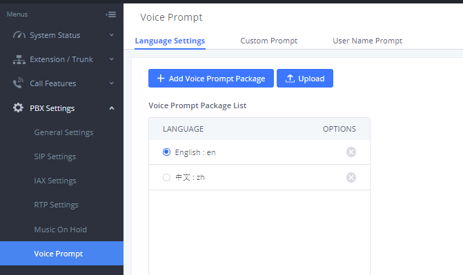
A new dialog window of voice prompt package list will be displayed. Users can see the version number (latest version available V.S. current installed version), package size and options to upgrade or download the language.
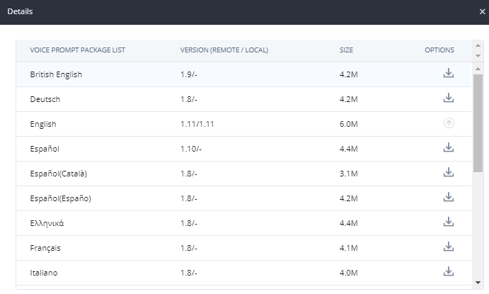
Click on ![]() to download the language to the UCM6510. The installation will be automatically started once the downloading is finished.
to download the language to the UCM6510. The installation will be automatically started once the downloading is finished.
A new language option will be displayed after successfully installed. Users then could select it to apply in the UCM6510 system voice prompt or delete it from the UCM6510.
Upload Language Package
On the UCM6510, if the user needs to replace some specific customized prompt, the user can upload a single specific customized prompt from Web GUI🡪PBX Settings🡪Voice Prompt🡪Language Settings instead of the entire language pack.

The package file should follow below requirements:
- Each file uploaded must be under 50MB.
- Package structure:
[Package]
├ [voice prompt dir]
│ ├ [... dir]
│ └ [... files]
└ info.txt (containing the language name for display, in UTF8)
- Language dir name format:
- Custom dir name format: language_xxx;
For example: If there is a Chinese custom directory named zh_xxx, the custom voice prompt in zh_xxx would be used first, then the Chinese voice prompt zh, then use the default language prompt (en); If not named the format as above, then the custom prompt will be used first, then use the default language prompt (en).
For more details, please refer to:
https://www.grandstream.com/sites/default/files/Resources/ucm_voiceprompt_customization_guide.zip
Custom Prompt
Record New Custom Prompt
In the UCM6510 Web GUI🡪PBX Settings🡪Voice Prompt🡪Custom Prompt page, click on “Record New IVR Prompt” and follow the steps below to record new IVR prompt.
- Specify the IVR file name.
- Select the format (GSM or WAV) for the IVR prompt file to be recorded.
- Select the extension to receive the call from the UCM6510 to record the IVR prompt.
- Click the “Record” button. A request will be sent to the UCM6510. The UCM6510 will then call the extension for recording the IVR prompt from the phone.
- Pick up the call from the extension and start the recording following the voice prompt.
- The recorded file will be listed in the IVR Prompt web page. Users could select to re-record, play or delete the recording.
Upload Custom Prompt
If the user has a pre-recorded IVR prompt file, click on “Upload IVR Prompt” in Web GUI🡪PBX Settings🡪Voice Prompt🡪Custom Prompt page to upload the file to the UCM6510. The following are required for the IVR prompt file to be successfully uploaded and used by the UCM6510:
- PCM encoded.
- 16 bits.
- 8000Hz mono.
- In .mp3 or .wav format; or raw/ulaw/alaw/gsm file with .ulaw or .alaw suffix.
- File size under 5MB.
- Filename should not exceed 100 characters.
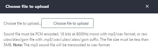
Click on “choose file to upload” to select audio file from local PC and to start uploading. Once uploaded, the file will appear in the IVR Prompt web page.
Download All Custom Prompt
On the UCM6510, the users can download all custom prompts from UCM Web GUI to local PC. To download all custom prompt, log in UCM Web GUI and navigate to PBX Settings🡪Voice Prompt🡪Custom Prompt and click on ![]() . The following window will pop up in order to set a name for the downloaded file.
. The following window will pop up in order to set a name for the downloaded file.
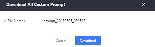
Username Prompt Customization
There are two ways to customize/set new username prompt:
Upload Username Prompt File from Web GUI
- First, Users should have a pre-recorded file respecting the following format:
- PCM encoded / 16 bits / 8000Hz mono.
- In “.GSM” or “.WAV” format.
- File size under 5MB.
- Filename must be set as the extension number with 18 characters max. For example, the recorded file name 1000.wav will be used for extension 1000.
- Go under web GUI PBX Settings 🡪 Voice Prompt 🡪 Username Prompt and click on
 button.
 - Select the recorded file to upload it and press Save and Apply Settings.
- To delete username prompts, either click on the button to delete a single file or select multiple files and click on Delete button to delete selected prompts at once.
Record Username via Voicemail Menu
The second option to record username is using voicemail menu, please follow below steps:
- Dial *98 to access the voicemail
- After entering the desired extension and voicemail password, dial “0” to enter the recordings menu and then “3” to record a name.
Another option is that each user can record their own name by following below steps:
- The user dials *97 to access his/her voicemail
- After entering the voicemail password, the user can press “0” to enter the recordings menu and then “3” to record his name.
Voicemail
Configure Voicemail
If the voicemail is enabled for UCM6510 extensions, the configurations of the voicemail can be globally set up and managed under Web GUI🡪Call Features🡪Voicemail.
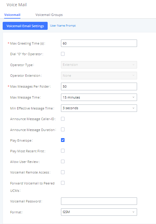
|
Max Greeting |
Configure the maximum number of seconds for the voicemail greeting. The default setting is 60 seconds. |
|
Dial ‘0’ For Operator |
If enabled, the caller can press 0 to exit the voicemail application and connect to the configured operator’s extension. |
|
Operator Type |
Select extension or Ring group as Operator type. |
|
Operator Extension |
Select the operator extension, which will be dialed when users press 0 to exit voicemail application. The operator extension can also be used in IVR option. |
|
Max Messages Per Folder |
Configure the maximum number of messages per folder in users’ voicemail. The valid range 10 to 1000. The default setting is 50. |
|
Max Message Time |
Select the maximum duration of the voicemail message. The message will not be recorded if the duration exceeds the max message time. The default setting is 15 minutes. The available options are:
|
|
Min Effective Message Time |
Configure the minimum effective duration (in seconds) of a voicemail message. Messages will be automatically deleted if the duration is shorter than the Min Effective Message Time. The default setting is 3 seconds. The available options are:
Note: Silence and noise duration are not counted in message time. |
|
Announce Message Caller-ID |
If enabled, the caller ID of the user who has left the message will be announced at the beginning of the voicemail message. The default setting is “No”. |
|
Announce Message Duration |
If enabled, the message duration will be announced at the beginning of the voicemail message. The default setting is “No”. |
|
Play Envelope |
If enabled, a brief introduction (received time, received from, and etc) of each message will be played when accessed from the voicemail application. The default setting is “Yes”. |
|
Play from Last |
If enabled, UCM6510 will play from the voice message left most recently; if disabled, UCM6510 will play from the earliest left voice message |
|
Allow User Review |
If enabled, users can review the message following the IVR before sending the message out. The default setting is “No”. |
|
If enabled, external callers routed by DID and reaching VM will be prompted by the UCM with 2 options:
To leave a message for the extension reached by DID.
This will allow caller to access any extension VM after entering extension number and its VM password. Note: This option applies to inbound call routed by DID only. The default setting is “Disabled”. | |
|
Enables the forwarding of voicemail to remote extensions on peered SIP trunks. The default setting is “Disabled”. | |
|
Configures the Voicemail password that will be used for extensions that are reset. | |
|
Format |
Select WAV or GSM format. |
Access Voicemail
If the voicemail is enabled for UCM6510 extensions, the users can dial the voicemail access number (by default *97) to access their extension’s voicemail. The users will be prompted to enter the voicemail password and then can enter digits from the phone keypad to navigate in the IVR menu for different options.
Otherwise the user can dial the voicemail access code (by default *98) followed by the extension number and password in order to access to that specific extension’s voicemail.
Main Menu | Sub Menu 1 | Sub Menu 2 |
1 – New messages | 3 - Advanced options | 1 - Send a reply |
2 - Call the person who sent this message | ||
3 - Hear the message envelop | ||
4 - Leave a message | ||
* - Return to the main menu | ||
5 - Repeat the current message | ||
7 - Delete this message | ||
8 - Forward the message to another user | ||
9 – Save | ||
* - Help | ||
# - Exit | ||
2 – Change folders | 0 - New messages | |
1 - Old messages | ||
2 - Work messages | ||
3 - Family messages | ||
4 - Friend messages | ||
# - Cancel | ||
3 – Advanced options | 1 - Send a reply | |
2 - Call the person who sent this message | ||
3 - Hear the message envelop | ||
4 - Leave a message | ||
* - Return to the main menu | ||
0 – Mailbox options | 1 - Record your unavailable message | 1 - Accept this recording |
2 - Listen to it | ||
3 - Re-record your message | ||
2 - Record your busy message | 1 - Accept this recording | |
2 - Listen to it | ||
3 - Re-record your message | ||
3 - Record your name | 1 - Accept this recording | |
2 - Listen to it | ||
3 - Re-record your message | ||
4 - Record temporary greeting | 1 - Accept this recording | |
2 - Listen to it | ||
3 - Re-record your message | ||
5 - Change your password | ||
* - Return to the main menu |
Leaving Voicemail
If an extension has voicemail enabled under basic settings “Extension/Trunk 🡪 Extensions 🡪 Basic Settings” and after a ring timeout or user not available, the caller will be automatically redirected to the voicemail in order to leave a message on which case they can press # in order to submit the message.
In case if the caller is calling from an internal extension, they will be directly forwarded to the extension’s voicemail box. But if the caller is calling from outside the system and the incoming call is routed by DID to the destination extension, then the caller will be prompted with the choice to either press1 to access voicemail management or press 2 to leave a message for the called extension. This feature could be useful for remote voicemail administration.
Voicemail Email Settings
The UCM6510 can be configured to send the voicemail as attachment to Email. Click on “Voicemail Email Settings” button to configure the Email attributes and content.
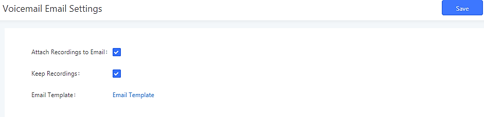
Click on “Email Template” button to view the default template as an example.
|
Send Voicemail to Email |
If enabled, voicemails will be sent to user’s Email address. The default setting is “Yes”. |
|
Keep Recordings |
If enabled, voicemail will be stored in the UCM6510 after email is sent. The default setting is “Yes”. |
|
Template For Voicemail Emails |
Fill in the “Subject:” and “Message:” content, to be used in the Email when sending to the user. The template variables are:
|
Configure Voicemail Group
The UCM6510 supports voicemail group and all the extensions added in the group will receive the voicemail to the group extension. The voicemail group can be configured under Web GUI 🡪 Call Features 🡪 Voicemail Group. Click on “Create New Voicemail Group” to configure the group.
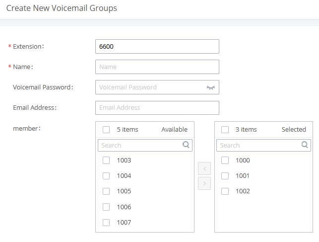
|
Voicemail Group Extension |
Enter the Voicemail Group Extension. The voicemail messages left to this extension will be forwarded to all the voicemail group members. |
|
Name |
Configure the Name to identify the voicemail group. Letters, digits, _ and – are allowed. |
|
Voicemail Password |
The Voicemail password for the user to check Voicemail messages. |
|
Email Address |
The Email address of current user. |
|
Select available extensions from the left list and add them to the right list. The extensions need to have voicemail enabled to be listed in available mailboxes list. Note: Members selected cannot exceed 30 extensions. |
Ring Group
The UCM6510 supports ring group feature with different ring strategies applied to the ring group members. This section describes the ring group configuration on the UCM6510.
Configure Ring Group
Ring group settings can be accessed via Web GUI🡪Call Features🡪Ring Group.

- Click on “Create New Ring Group” to add ring group.
- Click on to edit the ring group. The following table shows the ring group configuration parameters.
- Click on to delete the ring group.
|
Ring Group Name |
Configure ring group name to identify the ring group. Letters, digits, _ and – are allowed. |
|
Extension |
Configure the ring group extension. |
|
Members |
Select available users from the left side to the ring group member list on the right side. Click on |
|
LDAP Phonebook |
Select available remote users from the left side to the ring group member list on the right side. Click on |
|
Ring Strategy |
Select the ring strategy. The default setting is “Ring in order”.
Ring all the members at the same time when there is incoming call to the ring group extension. If any of the member answers the call, it will stop ringing.
Ring the members with the order configured in ring group list. If the first member does not answer the call, it will stop ringing the first member and start ringing the second member. |
|
Music On Hold |
Select the “Music On Hold” Playlist of this Ring Group, “Music On Hold” can be managed from the “Music On Hold” panel on the left. |
|
This option is to set a custom prompt for a ring group to announce to caller. Click on ‘Prompt’, it will direct the users to upload the customized voice prompts. Note: Users can also refer to the page PBX Settings🡪Voice Prompt🡪Custom Prompt, where they could record new prompt or upload prompt files. | |
|
Ring Timeout for Each Member |
Configure the number of seconds to ring each member. If set to 0, it will keep ringing. The default setting is 30 seconds. Note: The actual ring timeout might be overridden by users if the phone has ring timeout settings as well. |
|
Auto Record |
Once this option is enabled, the calls using this extension or trunk will be automatically recorded. |
|
This allows the UCM to work with endpoint-configured call forwarding settings to redirect calls to ring group. For example, if a member wants to receive calls to the ring group on his mobile phone, he would have to set his endpoint’s call forwarding settings to his mobile number. By default, it is disabled. Note: However, this feature has the following limitations:
| |
|
If enabled, the UCM will replace the caller display name with the Ring Group name the caller know whether the call is incoming from a direct extension or a Ring Group. | |
|
If enabled calls to busy agents will be skipped regardless of call waiting settings and sent to the following available ones. Default is enabled. | |
|
If enabled, users could select extension, voicemail, ring group, IVR, call queue, voicemail group as the destination if the call to the ring group has no answer. Note: Voicemail Password and Email address (limited by 128 characters) are required if voicemail is selected as the destination. Voicemail system will mention if a voicemail is from a ring group. | |
|
Default Destination |
Configure the Default Destination. |
Remote Extension in Ring Group
Remote extensions from the peer trunk of a remote UCM6510 can be included in the ring group alongside local extensions. An example of Ring Group with peer extensions is presented in the following:
- Create SIP Trunks from UCM A to UCM B and vise-versa on the Extension/Trunk🡪VoIP Trunks. Additionally, please create the appropriate outbound and inbound routes for these SIP trunks.
- Click edit button in the menu , and check if Sync LDAP Enable is toggled on.
- In the scenario that the LDAP is not synced automatically, users can manually sync LDAP phonebooks by clicking on the LDAP sync button that’s highlighted in the following image.
- Under Ring Groups setting page, click
 . Ring Groups will be available under Web GUI🡪Call Features🡪Ring Groups.
 - If LDAP phonebook has synced correctly, the remote UCM’s extensions should appear in the Created/Edit Ring Group🡪LDAP phonebook list.
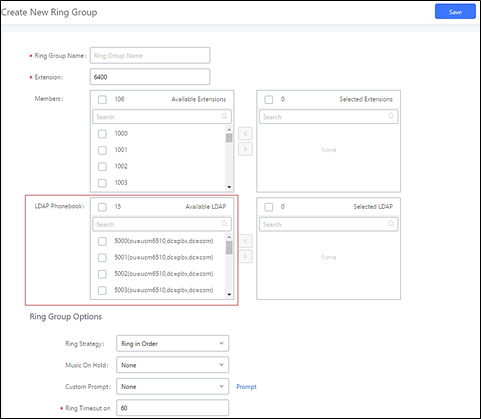
Restrict Calls
The Restrict Calls feature allows users to restrict calls between extensions. This section describes the configuration of Restrict Calls feature under Web GUI🡪Call Features🡪Restrict Calls.
- Click on “Add” to add paging/intercom group.
- Click on to edit the paging/intercom group.
- Click on to delete the paging/intercom group.
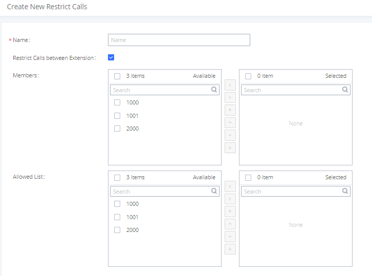
|
Name |
Configure restrict calls name. |
|
Restrict Calls between Extension |
Toggles the restriction rule on/off. |
|
Members |
Selected extensions will not be able to call any extensions besides those in the Allowed List. |
|
Allowed List |
The extensions configured in the Members list will only be able to call the extensions selected in this list |
Paging and Intercom Group
Paging and Intercom Group can be used to make an announcement over the speaker on a group of phones. Targeted phones will not ring but answer immediately using speaker. The UCM6510 paging and intercom can be used via feature code to a single extension or a paging/intercom group. This section describes the configuration of paging/intercom group under Web GUI🡪Call Features🡪Paging/Intercom.
Configure Paging/Intercom Group
- Click on “Add” to add paging/intercom group.
- Click on to edit the paging/intercom group.
- Click on to delete the paging/intercom group.
- Click on “Paging/Intercom Group Settings” to edit Alert-Info Header. This header will be included in the SIP INVITE message sent to the callee in paging/intercom call.
Configure Multicast Paging
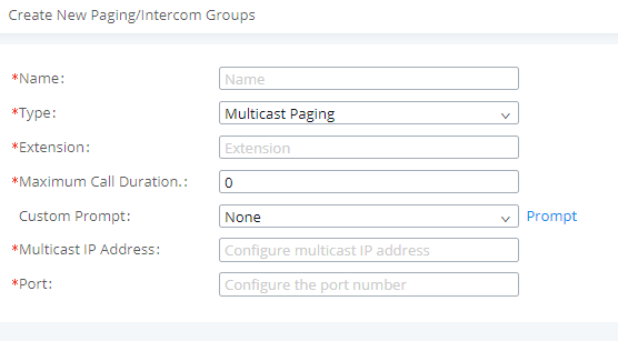
|
Name |
Configure paging/intercom group name. |
|
Type |
Select “Multicast Paging”. |
|
Extension |
Configure the paging/intercom group extension. |
|
Multicast IP Address |
The allowed multicast IP address range is 224.0.1.0 – 238.255.255.255. Note: This field appears only when “Type” is set to “Multicast Paging”. |
|
Maximum Call Duration |
Specify the maximum call duration in seconds. The default value 0 means no limit. |
|
Custom Prompt |
Configure a custom prompt to play to paging callees. Users can now directly upload custom prompts from this page. They do not need to be redirected anymore. |
|
Multicast IP Address |
Configure the multicast IP address that endpoints will listen to. |
|
Port |
Configure the port for multicast paging. Note: This field appears only when “Type” is set to “Multicast Paging”. |
Configure 2-way Intercom

|
Name |
Configure paging/intercom group name. |
|
Type |
Select “2-way Intercom”. |
|
Extension |
Configure the paging/intercom group extension. |
|
Replace Display Name |
If enabled, the UCM will replace the caller display name with Paging/Intercom name. |
|
Maximum Call Duration |
Specify the maximum call duration in seconds. The default value 0 means no limit. |
|
Custom Prompt |
This option is to set a custom prompt for a paging/intercom group to announce to caller. Users can now directly upload custom prompts from this page. They do not need to be redirected anymore. |
|
Members |
Select available users from the left side to the paging/intercom group member list on the right. |
|
Paging/Intercom Whitelist |
Select which extensions are allowed to use the paging/intercom feature for this paging group. |
Configure 1-way Paging
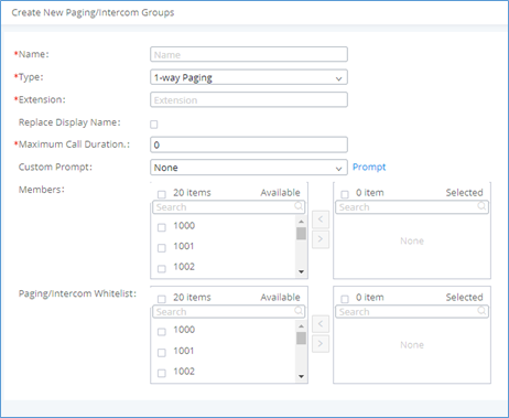
|
Name |
Configure paging/intercom group name. |
|
Type |
Select “1-way Paging”. |
|
Extension |
Configure the paging/intercom group extension. |
|
Replace Display Name |
If enabled, the UCM will replace the caller display name with Paging/Intercom name. |
|
Maximum Call Duration |
Specify the maximum call duration in seconds. The default value 0 means no limit. |
|
Custom Prompt |
This option is to set a custom prompt for a paging/intercom group to announce to caller. Users can now directly upload custom prompts from this page. They do not need to be redirected anymore. |
|
Members |
Select available users from the left side to the paging/intercom group member list on the right. |
|
Paging/Intercom Whitelist |
Select which extensions are allowed to use the paging/intercom feature for this paging group. |
Configure Announcement Paging
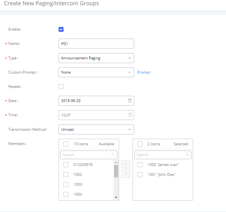
|
Enable/Disable Announcement Paging. | |
|
Name |
Configure paging/intercom group name. |
|
Type |
Select “Announcement Paging”. |
|
Custom Prompt |
This option is to set a custom prompt for a paging/intercom group to announce to caller. Users can now directly upload custom prompts from this page. They do not need to be redirected anymore. |
|
Repeat |
If enabled, the announcement page will be repeated for the selected weekdays. |
|
Include Holidays |
Announcement Paging will run during holidays. |
|
Date | |
|
Time |
Configure Announcement Paging Time. |
|
Transmission Method |
Configure Announcement Paging transmission method.
|
|
Members |
Select available users from the left side to the paging/intercom group member list on the right. |
Configure Private Intercom
Private Intercom is a new paging type that is meant to be used with Grandstream GSC3510.
http://www.grandstream.com/products/facility-management/intercoms-paging/product/gsc3510
In a private intercom:
- The initiator can be heard by all parties
- The initiator can hear only one of the intercom members, which is determined by whose audio is initially detected. Audio from other members cannot be heard until the first responder is done talking.
- Intercom members can hear only the initiator’s audio and not other intercom members
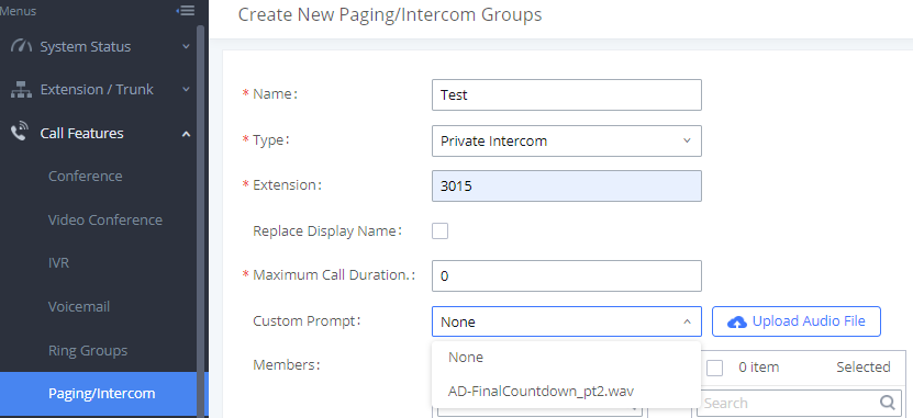
|
Name |
Configure paging/intercom group name. |
|
Type |
Select “Private Intercom”. |
|
Extension |
Configure the paging/intercom group extension. |
|
Replace Display Name |
If enabled, the UCM will replace the caller display name with Paging/Intercom name. |
|
Maximum Call Duration |
Specify the maximum call duration in seconds. The default value 0 means no limit. |
|
Custom Prompt |
This option is to set a custom prompt for a paging/intercom group to announce to caller. Click on ‘Prompt’, it will direct the users to upload the customized voice prompts. Note: Users can also refer to the page PBX Settings🡪Voice Prompt🡪Custom Prompt, where they could record new prompt or upload prompt files. |
|
Members |
Select available users from the left side to the paging/intercom group member list on the right. |
|
Paging/Intercom Whitelist |
Select which extensions are allowed to use the paging/intercom feature for this paging group. |
Paging/Intercom Group Settings
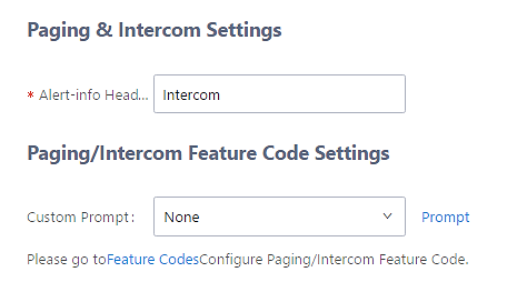
The UCM6510 has pre-configured paging/intercom feature code. By default, the Paging Prefix is *81 and the Intercom Prefix is *80. To edit page/intercom feature code, click on “Feature Codes” in the “Paging/Intercom Group Settings” dialog. Or users could go to Web GUI🡪Call Features🡪Feature Codes directly.
Configure a Scheduled Paging/Intercom
Users can schedule paging/intercom calls by using the Schedule Paging/Intercom page. To schedule, click the Add button on the new page and configure the caller, the group to use, and the time to call out.
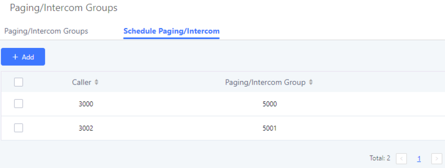
|
Caller |
Configure the caller ID for the paging / intercom group. |
|
Paging/Intercom Group |
Select the paging / intercom group from the list of the available groups. |
|
Type |
Select the type for the scheduled paging / intercom call. The available types are: Single time or Daily, Weekly basis. Default is “Single”. |
|
Start Time |
Configure the start time of the scheduled paging / intercom call. |
|
If enabled Paging/Intercom will run during holidays. | |
|
Action Status |
Display the action status of the scheduled paging / intercom call. |
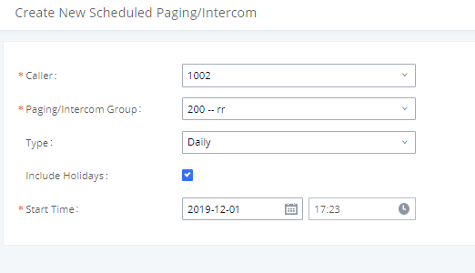
Call Queue
The UCM6510 provides call center functionality through its Call Queue feature. Static and dynamic agents can be assigned to queue groups to handle varying loads of call traffic. This section describes the configuration of call queues in the Call Features🡪Call Queue page.
Configure Call Queue
Call queue settings can be accessed via Web GUI🡪Call Features🡪Call Queue.
- Click on to add call queue.
- Click on to edit the call queue. The call queue configuration parameters are listed in bellow table.
- Click on to delete the call queue.
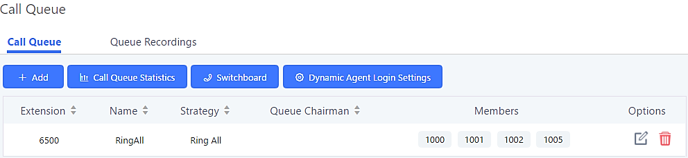
|
Basic Settings | |
|
Extension |
Configure the call queue extension number. |
|
Name |
Configure the call queue name to identify the call queue. |
|
Strategy |
Select the strategy for the call queue.
Ring all available Agents simultaneously until one answers.
Ring agents in the specified order.
Ring the agent who has been called the least recently.
Ring the agent with the fewest completed calls.
Ring a random agent.
Ring the agents in Round Robin scheduling with memory. The default setting is “Ring All”. |
|
Music On Hold |
Select the Music On Hold playlists for the call queue. Note: Music On Hold playlist can be managed from Web GUI 🡪 PBX Settings 🡪 Music On Hold. |
|
Max Queue Length |
Configure the maximum number of calls that can be queued up at once. This number does not include calls that have been connected with agents. It only includes calls not connected yet. The default setting is 0, which means unlimited. When the maximum value is reached, the caller will be treated with busy tone followed by the next calling rule after attempting to enter the queue. |
|
Wrapup Time |
Configure the number of seconds an agents must wait to receive a new call after completing a previous call. If set to 0, an agent can receive a new call as soon as a previous call is completed. Default is 10 seconds. |
|
Retry Time |
Configure the number of seconds to wait before ringing the next agent. |
|
Ring Time |
Configure the number of seconds to ring an agent before proceeding to ring the next agent. The default setting is 30 seconds. |
|
Auto Record |
If enabled, the calls on the call queue will be automatically recorded. The recording files can be accessed in Queue Recordings under Web GUI🡪Call Features🡪Call Queue. |
|
If enabled, call queue members can use recording feature code to pause or restore current queue’s recording when Auto Record is enabled for the queue. Default code for Start/Stop Call Recording is *3. | |
|
If enabled, users can upload an audio file that will be played as an Initial tone when dialing the queue number. | |
|
When the agent hangs up, the system will play the prompt to ask the caller to rate their satisfaction scale from 1 to 5, where 5 is the highest. | |
|
Configure the maximum amount of seconds callers can wait before being disconnected from the queue. Default setting is 60 seconds, if left blank, there will be no limit to the amount of time a caller waits in queue. Note: It is recommended to configure “Wait Time” longer than the “Wrapup Time”. | |
|
Configure the destination that callers will be redirected to after the configured Max Wait Time has passed. Default is “Hang up”. | |
|
If enabled, the agent call completion count will be reset based on the frequency set in the repeat and Date/Time fields. | |
|
Repeat |
Specifies the frequency at which the agent call counter will be reset. |
|
Destination Prompt Cycle |
Configure the frequency to play the destination prompt to callers waiting in queue. |
|
Custom Prompt |
The custom prompt to play to callers waiting in queue once the destination prompt cycle period has been reached. Callers can press 1 to be redirected to the destination configured in Destination. |
|
Destination |
Select failover destination to redirect callers to after pressing 1 during the custom prompt. |
|
Advanced Settings | |
|
Refer to Call Center Settings & Enhancements section for detailed information about these features. |
|
Enable Agent Login |
Enables quick static agent login/logout via GXP21xx softkeys. Supports GXP21XX endpoint on firmware 1.0.9.18 and higher. |
|
Leave When Empty |
Configure whether or not callers will be disconnected from the queue based on agent availability.
Callers will be disconnected from the queue if all agents are paused or unavailable.
Never disconnect the callers from the queue when the queue is empty.
Callers will be disconnected from the queue if there are no agents logged in or if all agents are paused or unavailable. |
|
Dial in Empty Queue |
Configure whether the callers can dial into a call queue if the queue has no agent. The default setting is “No”.
Callers can always dial into a call queue.
Callers cannot dial into a queue if all agents are paused or unavailable.
Callers will be disconnected from the queue if there are no agents logged in or if all agents are paused or unavailable. |
|
Failover Destination |
Configure the destination to redirect callers to base on the Leave When Empty and Dial in Empty Queue values:
|
|
Report Hold Time |
If enabled, the UCM6510 will report to the agent the amount of time of the caller waited before being connected. The default is disabled. |
|
If enabled, the UCM will replace the caller display name with the Call Queue name so that the caller knows the call is incoming from a Call Queue. | |
|
Enable feature codes option for call queue. For example, *83 is used for “Agent Pause”. Note: Callers can no longer use feature codes in established callbacks. | |
|
Dynamic Login Password |
If enabled, the configured PIN number is required for dynamic agent to log in. The default setting is disabled. |
|
Configure the call destination for the call to be routed to if no agent in this call queue answers the call. | |
|
Agents | |
|
Agents |
Go to “Agents” Tab and Select the available users to be the static agents in the call queue. Choose from the available users on the left to the static agents list on the right. Click on |
To guarantee a high level of audio quality with the call queue feature, UCMs will limit the number of static agents allowed to be assigned depending on the UCM model used. If the user attempts to configure the number of static agents to be more than the maximum allowed number, a warning message will appear.
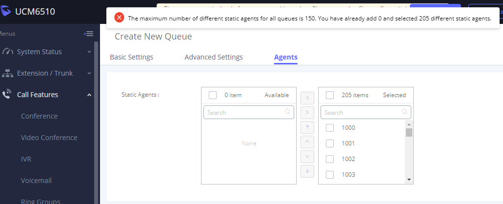
The following table lists the maximum number of static agents for each UCM model:
| UCM Model | Max Static Agents in Call Queue |
|---|---|
|
UCM6202 |
22 |
|
UCM6204 |
23 |
|
UCM6208 |
34 |
|
UCM6510 |
75 |
- Click on “Global Queue Settings” to configure Agent Login Extension Postfix and Agent Logout Extension Postfix. Once configured, users could log in the call queue as dynamic agent.
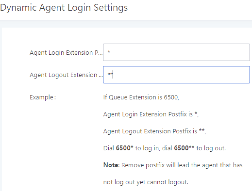
For example, if the call queue extension is 6510, Agent Login Extension Postfix is * and Agent Logout Extension Postfix is **, users could dial 6510* to login to the call queue as dynamic agent and dial 6510** to logout from the call queue. Dynamic agent does not need to be listed as static agent and can log in/log out at any time.
- Call queue feature code “Agent Pause” and “Agent Unpause” can be configured under Web GUI🡪Call Features🡪Feature Codes. The default feature code is *83 for “Agent Pause” and *84 for “Agent Unpause”.
- Queue recordings are shown on the Call Queue page under “Queue Recordings” Tab. Click on to download the recording file in .wav format; click on to delete the recording file. To delete multiple recording files by one click, select several recording files to be deleted and click on “Delete Selected Recording Files” or click on “Delete All Recording Files” to delete all recording files.
Call Center Settings & Enhancements
UCM supports additional call center features such as virtual call queue and position announcement, allowing callers to know their current position in the queue and providing them the option to either stay in the queue or request for callback once an agent is available.
To configure these, click on the ![]() button for a queue group and click on the Advanced Settings tab. The following options are available:
button for a queue group and click on the Advanced Settings tab. The following options are available:
|
Enable Virtual Queue |
Enable virtual queue to activate call center features. |
|
Virtual Queue Period |
Configure the amount of seconds a caller must wait before the virtual queue prompts is played to them. Default is 20 sec. |
|
Virtual Queue Mode |
Timeout Mode: After the virtual queue period passes, the caller will enter the virtual call queue and be presented with a menu to choose an option, the choices can be customized from Global Queue Settings page. DTMF Mode: on this mode, the callers can activate the virtual queue by pressing 2, then they will be presented with the menu to choose an option as bellow:
|
|
Virtual Queue Outbound Prefix |
System will add this prefix to dialed numbers when calling back users. |
|
Enable Virtual Queue Timeout |
If enabled agents will have a set amount of time to answer a virtual queue callback. |
|
Write Timeout |
Configure the virtual queue callback timeout period in seconds. |
|
If enabled, callers’ position in queue will be announced based on the frequency set in Position Announcement Interval Note: Queue position will be announced to the caller upon entering the queue. | |
|
Position Announcement Interval |
Configure the frequency of the caller position announcement. |
|
Enable Hold time Announcement |
Enable the announcement of the estimated hold time to the caller periodically. Note: Hold time will not be announced if less than one minute. |
|
Select the extension to act as chairman of the queue (monitoring). Note: One queue can have up to 3 chairmen. | |
|
Enables quick static agent login/logout via GXP21xx softkeys. Supports GXP21XX endpoint on firmware 1.0.9.18 and higher. Notes:
| |
|
Autofill |
Toggles the way UCM handles and distributes call traffic |
In previous UCM firmware, the call queue has a serial type behavior in that the queue will make all waiting callers wait in the queue even if there is more than one available agents ready to take calls until the head caller is connected with the member they were trying to get to. The next waiting caller in line then becomes the head caller, and they are then connected with the next available member and all available members and waiting callers waits while this happens.
Starting from 1.0.14.x, the waiting callers are connecting with available members in a parallel fashion until there are no more available members or no more waiting callers.
For example, in a call queue with linear method, if there are two available agents, when two callers call in the queue at the same time, UCM will assign the two callers to each of the two available agents at the same time, rather than assigning the second caller to second available agent after the first agent answers the call from the first caller
Queue Statistics
Along with the mentioned call center features; UCM6510 offers detailed call queue statistics, allowing system administrators to make informed decisions regarding call distribution and handling.
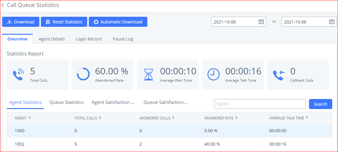
Select the time interval along with the queue(s) and agent(s) to get detailed statistics.
User can download statistics on CSV format by clicking on the download button ![]() , also the statistics can be cleared using “Clear Statistics” button
, also the statistics can be cleared using “Clear Statistics” button ![]() .
.
The statistics can be automatically sent to a specific email address on a preconfigured Period, this can be done by clicking on “Automatic Download Settings” button ![]() , and user will be directed to below page where he can configure the download period (Day/Week/Month) and the Email where the statistics will be sent (Email settings should be configured correctly):
, and user will be directed to below page where he can configure the download period (Day/Week/Month) and the Email where the statistics will be sent (Email settings should be configured correctly):
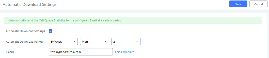
Significantly more information is now available UCM’s queue statistics page. In addition to the information presented in previous firmware, users can now view a call log that displays calls to all agents and queues, a dynamic agent login/logout record, and a pause log. Statistics reports for these new pages can be obtained by pressing the Download button in the top left corner of the Call Queue Statistics page. The reports are in .CSV format and will be packaged into a single tar.gz file upon download.
Agent Details
Agent Details is a call log that shows every call to each individual agent from all queues. The following information is available:
- Time – the date and time the call was received.
- Agent – the agent that was rung for the call.
- Queue – the queue that the call went to.
- Caller ID Number – the CID of the caller
- Abandoned – indicates whether the call was picked up or not by that specific agent. If the call rang several agents simultaneously, and this specific agent did not pick up the call, the call will be considered abandoned even if a different agent in the same queue picked it up.
- Wait Time – the amount of time that the call was waiting in queue after dialing in.
- Talk Time – the duration of the call after it was picked up by agent.
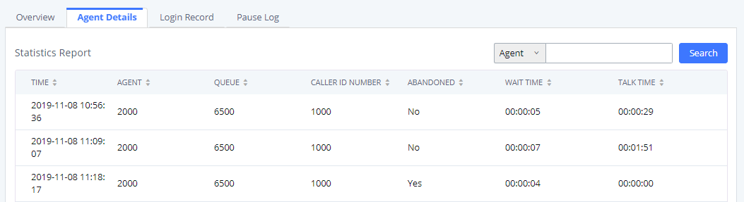
Login Record
Login Record is a report that shows the timestamps of dynamic agent logins and logouts and calculates the amount of time the dynamic agents were logged in. Dynamic agents are extensions that log in and out either via agent login/logout codes (configured in Global Queue Settings page) or by using the GXP21xx call queue softkey. A new record will be created only when an agent logs out. The following information is available:
- Agent – the extension that logged in and out.
- Queue – the queue that the extension logged in and out of.
- Login Time – the time that the extension logged into the queue.
- Logout Time – the time that the extension logged out of the queue.
- Login Duration – the total length of time that the extension was logged in.
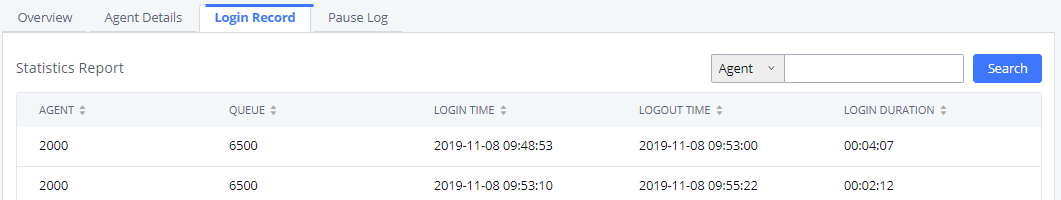
Pause Log
Pause Log is a report that shows the times of agent pauses and unpauses and calculates the amount of time that agents are paused. If an agent is part of several queues, an entry will be created for each queue. An entry will only be created after an agent unpauses. The following information is available:
- Agent – the extension that paused and unpaused
- Queue – the queue that the agent is in.
- Pause Time – the time that the agent paused.
- Resume Time – the time that the agent unpaused.
- Pause Duration – the total length of time the agent was paused for.
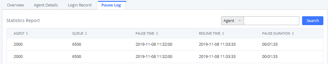
Global Queue Settings
As explained before, under this section users can configure the feature codes for Dynamic agent login and logout, and also can now customize the keys for virtual queue options like shown below.
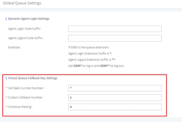
|
Dynamic Agent Login Settings | |
|
Agent Login Code Suffix |
Configure the code to dial after the queue extension to log into the queue (i.e. queue extension + suffix). |
|
Agent Logout Code Suffix |
Configure the code to dial after the queue extension to log out of the queue (i.e. queue extension + suffix). |
|
Call Back Current Number |
Press the feature key configured to set your current number as callback number. |
|
Custom Callback Number |
Press the feature key configured to set a custom callback number. |
|
Continue Waiting |
Press the feature key configured to continue waiting. |
Switchboard
Switchboard is a tool that allows system administrators and users to monitor and manage queues. This can be accessed from the Call Features🡪Call Queue page.
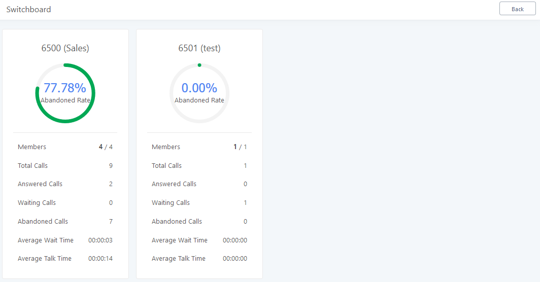
Clicking on one of the queues shown above will bring up the following window:
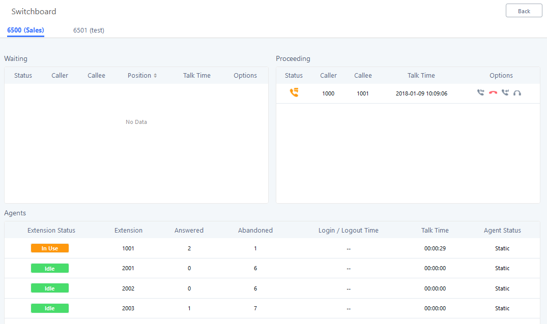
The table below gives a brief description for the main menus:
|
Waiting |
This menu shows the current waiting calls along with the caller id and the option to hang-up call by pressing on the |
|
Proceeding |
Shows the current established calls along with the caller id and the callee (agent) as well as the option to hang-up, transfer, add conference or barge-in the call. |
|
Agents |
Displays the list of agents in the queue and the extension status (idle, ringing, in use or unavailable) along with some basic call statistics and agent’s mode (static or dynamic). Note: the dashboard will show the number of calls (answered and abandoned) of each agent. For dynamic agents, it will count the number of calls starting from the last login time. |
There are three different privilege levels for Call Queue management from the switchboard: Super Admin, Queue Chairman, and Queue Agent.
- Super Admin – Default admin of the UCM. Call queue privileges include being able to view and edit all queue agents, monitor and execute actions for incoming and ongoing calls for each extension in Switchboard, and generate Call Queue reports to track performance.
- Queue Chairman – User appointed by Super Admin to monitor and manage an assigned queue extension via Switchboard. The Queue Chairman can log into the UCM user portal with his extension number and assigned user password. To access the Switchboard, click on “Value-added Features” in the side menu and click on “Call Queue”. In the image below, User 1012 is the Queue Chairman appointed to manage Queue Extension 6500 and can see all the agents of the queue in the Switchboard.
- Queue Agent – User appointed by Super Admin to be a member of a queue extension. A queue agent can log into the UCM user portal with his extension number and assigned user password. To access the Switchboard, click on “Value-added Features” in the side menu and click on “Call Queue”. However, a queue agent can view and manage only his own calls and statistics, but not other agents’ in the queue extension. In the image below, User 1000 is a queue agent and can see only his own information in the Switchboard.
Pickup Groups
The UCM6510 supports pickup group feature which allows users to pick up incoming calls for other extensions if they are in the same pickup group, by dialing “Pickup Extension” feature code (by default *8).
Configure Pickup Groups
Pickup groups can be configured via Web GUI🡪Call Features🡪Pickup Groups.
- Click on to create a new pickup group.
- Click on to edit the pickup group.
- Click on to delete the pickup group.
Select extensions from the list on the left side to the right side.
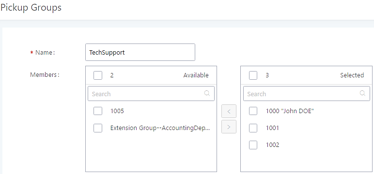
Configure Pickup Feature Code
When picking up the call for the pickup group member, the user only needs to dial the pickup feature code. It is not necessary to add the extension number after the pickup feature code. The pickup feature code is configurable under Web GUI🡪Call Features🡪Feature Codes.
The default pickup feature code is *8 as shown on the following screenshot.
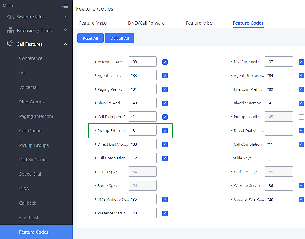
Music On Hold
Music On Hold settings can be accessed via Web GUI🡪PBX Settings🡪Music On Hold. In this page, users could configure music on hold playlist and upload music files. The “default” Music On Hold playlist already has 5 audio files defined for users to use.
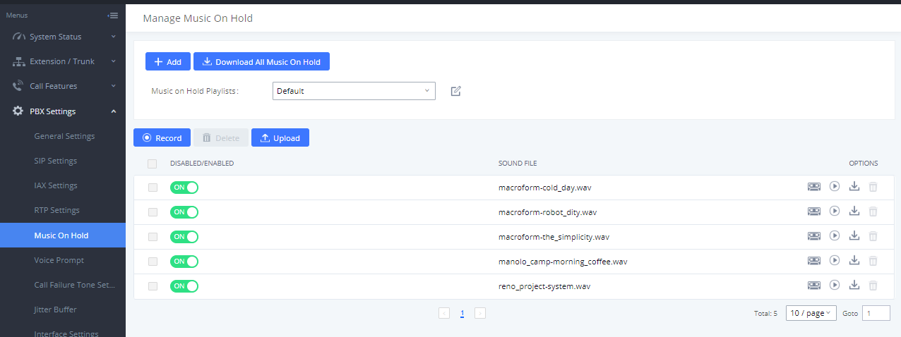
- Click on “Create New MOH Playlist” to add a new Music On Hold playlist.
- Click on to configure the MOH playlist sort method to be “Name” or “Random” for the sound files.
- Click on next to the selected Music On Hold playlist to delete this Music On Hold playlist.
- Click on Record to record the Music On Hold.
- Click on
 to start uploading. Users can upload:
 - Single files with 8KHz Mono Music file, or
- Music on hold files in a compressed package with .tar, .tar.gz and .tgz as the suffix. The file name can only be letters, digits or special characters -_
- the size for the uploaded file should be less than 30MB, the compressed file will be applied to the entire MoH.
- Users could also download all the music on hold files from UCM. In the Music On Hold page, click on
 and the file will be downloaded to your local PC.
 - Click on
 next to the sound file to disable it from the selected Music On Hold Playlist.
 - Click on
 next to the sound file to enable it from the selected Music On Hold Playlist.
 - Select the sound files and click on
 to delete all selected music on hold files.
The UCM can play selected MOH files to extensions by initiating calls to them from the Manage Music On Hold page.
Steps to play the music on hold file:
- Click on the button for the Music on Hold file.
- In the prompted window, select the extension to playback and click
 .
.
- The selected extension will ring.
- Answer the call to listen to the music playback.
Users could also record their own Music on hold to override an existing custom prompt, this can be done by following those steps:
- Click on
 .
. - A prompt of confirmation will pop up, as shown below.
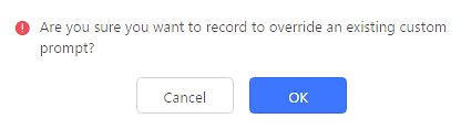
- Click
 .
. - In the prompted window, select the extension to playback and click
 .
.
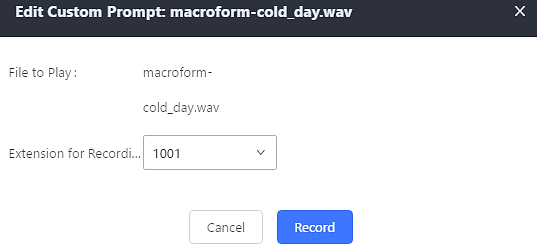
- Answer the call and start to record your new music on hold.
- Hangup the call and refresh Music On Hold page then you can listen to the new recorded file.
Fax Server
The UCM6510 supports T.30/T.38 Fax and Fax Pass-through. It can also convert the received Fax to PDF format and send it to the configured Email address. Fax/T.38 settings can be accessed via Web GUI🡪Call Features🡪Fax/T.38.
Configure Fax/T.38
- Click on “Create New Fax Extension”. In the popped-up window, fill the extension, name and Email address to send the received Fax to.
- Click on “Fax Settings” to configure the Fax parameters.
- Click on to edit the Fax extension.
- Click on to delete the Fax extension.
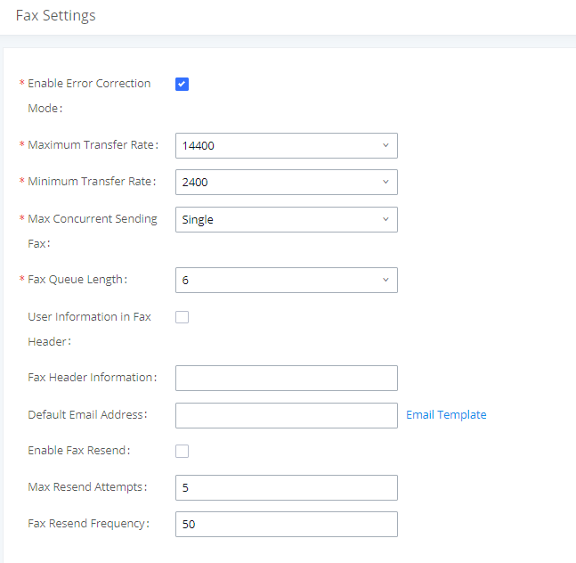
|
Enable Error Correction Mode |
Configure to enable Error Correction Mode (ECM) for the Fax. The default setting is “Yes”. |
|
Maximum Transfer Rate |
Configure the maximum transfer rate during the Fax rate negotiation. The possible values are 2400, 4800, 7200, 9600, 12000 and 14400. The default setting is 14400. |
|
Minimum Transfer Rate |
Configure the minimum transfer rate during the Fax rate negotiation. The possible values are 2400, 4800, 7200, 9600, 12000 and 14000. The default setting is 2400. |
|
Max Concurrent Sending Fax |
Configure the concurrent fax that can be sent by UCM6510.
By default, this option is set to “only”. |
|
Fax Queue Length |
Configure the maximum length of Fax Queue. |
|
Enable whether to send a special header in SIP fax messages. | |
|
Fax Header Information |
Adds fax header into the fax file. |
|
Default Email Address |
Configure the Email address to send the received Fax to if user’s Email address cannot be found. Note: The extension’s Email address or the Fax’s default Email address needs to be configured in order to receive Fax from Email. If neither of them is configured, Fax will not be received from Email. |
|
Template Variables |
Fill in the “Subject:” and “Message:” content, to be used in the Email when sending the Fax to the users. The template variables are:
|
|
Enables the fax resend option which allow the UCM to keep attempting to send faxes up to a specified amount of times. Additionally, if a fax still fails to send, a Resend button will appear in the File Send Progress list in Value-Added Features🡪Fax Sending to allow manual resending. | |
|
Configures the maximum attempts number to resend the fax. |
Receiving FAX
Example Configuration to Receive Fax from PSTN Line
The following instructions describe how to use the UCM6510 to receive fax from PSTN line on the Fax machine connected to the UCM6510 FXS port.
- Connect Fax machine to the UCM6510 FXS port.
- Connect PSTN line to the UCM6510 FXO port.
- Go to Web GUI🡪Extension/Trunk page.
- Create or edit the analog trunk for Fax as below.
Fax Detection: Make sure “Fax Detection” option is set to “No”.
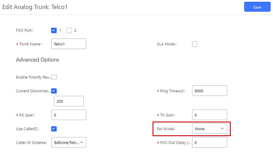
- Go to UCM6510 Web GUI🡪Extension/Trunk🡪Extensions page.
- Create or edit the extension for FXS port.
- Analog Station: Select FXS port to be assigned to the extension. By default, it is set to “None”.
- Once selected, analog related settings for this extension will show up in “Analog Settings” section.
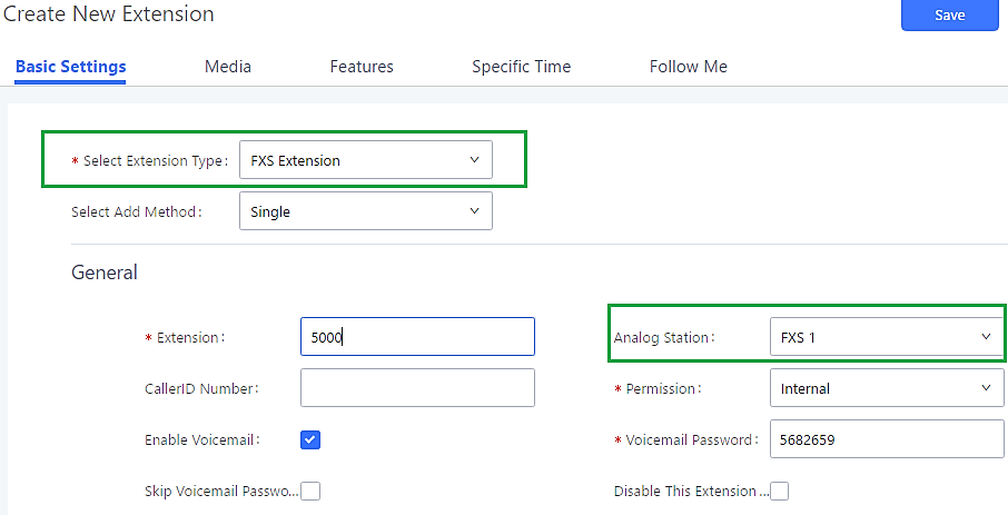
- Go to Web GUI🡪Extension/Trunk🡪Inbound Routes page.
- Create an inbound route to use the Fax analog trunk. Select the created extension for Fax machine in step 4 as the default destination.
Now the Fax configuration is done. When there is an incoming Fax calling to the PSTN number for the FXO port, it will send the Fax to the Fax machine.
Example Configuration for Fax-To-Email
The following instructions describe a sample configuration on how to use Fax-to-Email feature on the UCM6510.
- Connect PSTN line to the UCM6510 FXO port.
- Go to UCM6510 Web GUI🡪Internal Options🡪Fax/T.38 page. Create a new Fax extension.
- Go to UCM6510 Web GUI🡪Extension/Trunk🡪Analog Trunks page. Create a new analog trunk with “FAX Detection” set to “No”.
- Go to UCM6510 Web GUI🡪Extension/Trunk🡪Inbound Routes page. Create a new inbound route and set the default destination to the Fax extension.
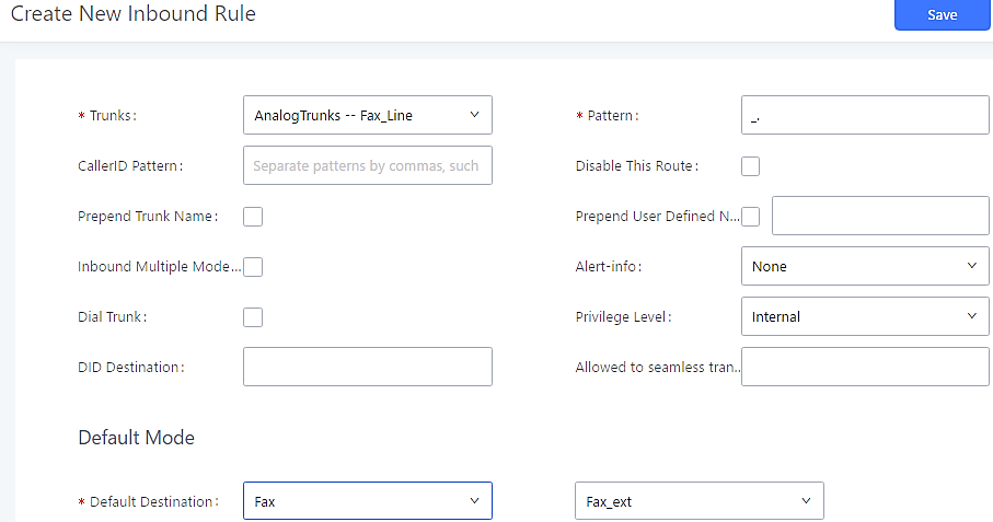
- Once successfully configured, the incoming Fax from external Fax machine to the PSTN line number will be converted to PDF file and sent to the Email address fax@domain.local as attachment.
Fax Sending
The UCM6510 supports sending Fax via Web GUI access. This feature can be found on Web GUI🡪Value-added Features🡪Fax Sending page. In order to send fax, pre-setup for analog trunk and outbound route is required.
After making sure analog trunk or VoIP Trunk is setup properly and UCM6510 can reach out to PSTN numbers via the trunk, on Fax Sending page, enter the fax number and upload the file to be faxed. Then click on “Send” to start. The progress of sending fax will be displayed in Web GUI. Users can also view the sending history is in the same web page.
Busy Camp-On
The UCM6510 supports busy camp-on/call completion feature that allows the PBX to camp on a called party and inform the caller as soon as the called party becomes available given the previous attempted call has failed.
The configuration and instructions on how to use busy camp-on/call completion feature can be found in the following guide:
https://documentation.grandstream.com/knowledge-base/busy-camp-on-2/
Presence
UCM supports SIP presence, allowing extensions to advertise their current availability for calls. This presence can be monitored by other users.
Presence is different from BLF in that SIP presence is a status that users can manually set themselves.
Users can change presence status from the webUI:
- Admin Portal: Navigate to Extension/Trunk🡪Extensions🡪Edit Extension🡪Features and click on the Presence Status dropdown list.
- User Portal: Navigate to Basic Information🡪Extensions🡪Features and click on the Presence Status dropdown list.
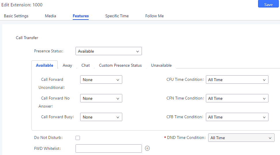
Select which status to set from the presence status selection drop list. The following options are available:
|
Available |
The contact is online and can participate in conversations/phone calls. |
|
Away |
The contact is currently away (ex: for lunch break). |
|
Chat |
The contact has limited conversation flexibility and can only be reached via chat. |
|
Do Not Disturb |
The Contact is on DND (Do Not Disturb) mode. |
|
Please enter the presence status for this mode on the Web GUI. Up to 64 characters. | |
|
Unavailable |
The contact is unreachable for the moment, please try to contact later. |
Users can also set presence status by dialing the feature code from their phones (*48 by default). The prompt will ask users what presence status they want to set.
The feature code can be enabled/customized from the Web GUI🡪Call Features🡪Feature Codes.
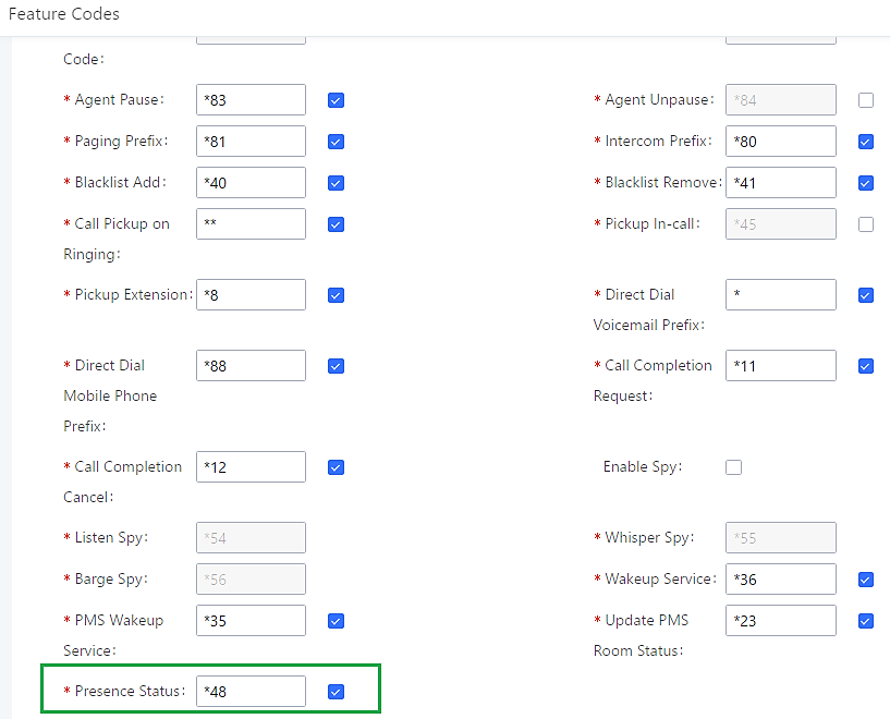
When a user does change his/her SIP presence status by making a call using presence feature code, the UCM will create a corresponding CDR entry showing the call as Action type = PRSENCE_STATUS.
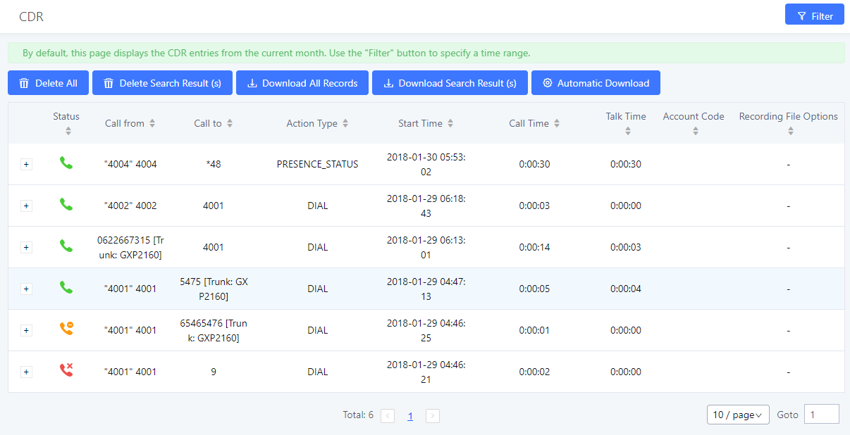
Follow Me
UCM supports Follow Me feature which allows users to direct calls to other phone numbers and have them ring all at once or one after the other. Calls can be directed to users’ home phone, office phone, mobile and etc. The calls will get to the user no matter where they are. Follow Me option can be found under extension settings page Web GUI🡪Extension/Trunk🡪Extensions.
To configure follow me:
- Choose the extension and click on .
- Go to the Follow me tab to add destination numbers and enable the feature.
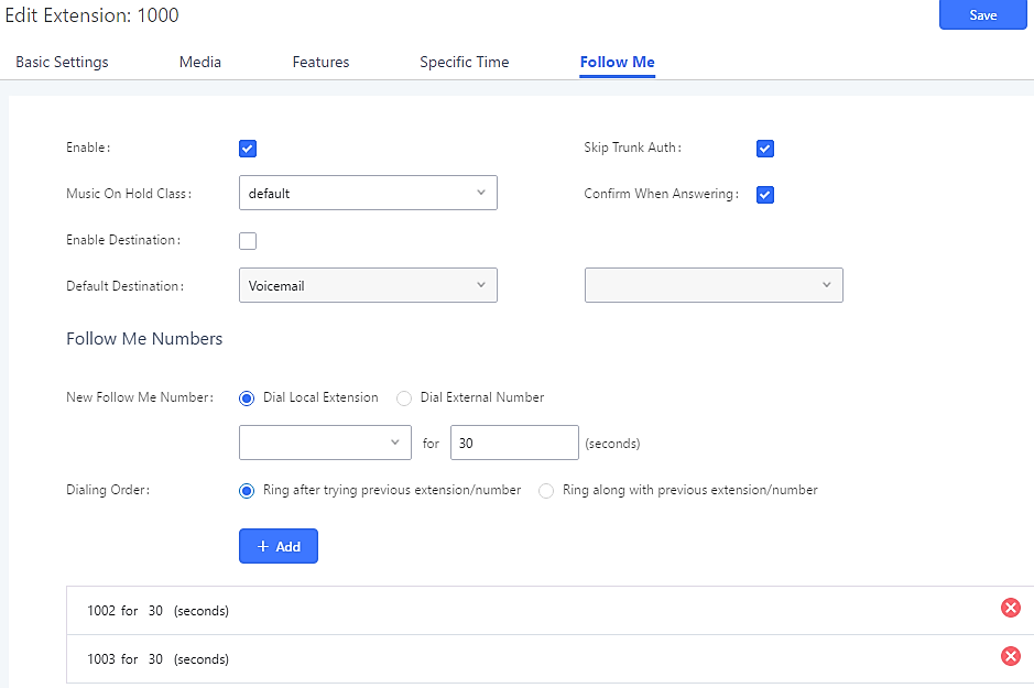
- Click on “Add Follow Me Number” to add local extensions or external numbers to be called after ringing the extension selected in the first step.
- Once created, it will be displayed on the follow me web page list. Click on to edit the Follow Me configuration. Click on to delete the Follow Me.
The following table shows the Follow Me configuration parameters.
|
Enable |
Configure to enable or disable Follow Me for this user. |
|
Skip Trunk Auth |
If external number is added in the Follow Me, please make sure this option is enabled or the “Skip Trunk Auth” option of the extension is enabled, otherwise the external Follow Me number cannot be reached. |
|
Music On Hold Playlist |
Configure the Music On Hold playlist that the caller would hear while tracking the user. |
|
Confirm When Answering |
By default, it is enabled, and user will be asked to press 1 to accept the call or to press 2 to reject the call after answering a Follow Me call. If it is disabled, the Follow Me call will be established once after the user answers it. |
|
Enable Destination |
If enabled, the call will be routed to the default destination if no one in the Follow Me answers the call. |
|
Default Destination |
Configure the destination if no one in the Follow Me answers the call, available options are: Extension Voicemail Queues Ring Group Voicemail Group IVR External Number |
|
Follow Me Numbers |
The added numbers are listed here. Click on |
|
New Follow Me Number |
Add a new Follow Me number which could be a ‘Local Extension’ or ‘External Number’. The selected dial plan should have permissions to dial the defined external number. |
|
Dialing Order |
Select the order in which the Follow Me destinations will be dialed to reach the user: ring all at once or ring one after the other. |
Click on “Follow Me Options” under Web GUI🡪Extension/Trunk🡪Extension page to enable or disable the options listed in the following table.
|
Playback Incoming Status Message |
If enabled, the PBX will playback the incoming status message before starting the Follow Me steps. |
|
Record the Caller’s Name |
If enabled, the PBX will record the caller’s name from the phone, so it can be announced to the callee in each step. |
|
Playback Unreachable Status Message |
If enabled, the PBX will playback the unreachable status message to the caller if the callee cannot be reached. |
Speed Dial
The UCM6510 supports Speed Dial feature that allows users to call specified destinations by pressing only 1-4 digits. This creates a system-wide speed dial access for all the extensions on the UCM6510.
To enable Speed Dial, on the UCM6510 Web GUI, go to page Web GUI🡪Call Features🡪Speed Dial.
User should first click on ![]() . Create a speed dial extension and assign a destination to it. Supported destinations are Extension, Conference Room, Video Conference Room, Voicemail, Voicemail Group, IVR, Ring Group, Queue, Paging/Intercom Group, Fax, DISA, Dial by Name, Announcement, and External Number.
. Create a speed dial extension and assign a destination to it. Supported destinations are Extension, Conference Room, Video Conference Room, Voicemail, Voicemail Group, IVR, Ring Group, Queue, Paging/Intercom Group, Fax, DISA, Dial by Name, Announcement, and External Number.
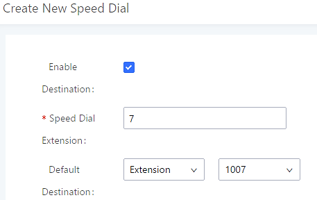
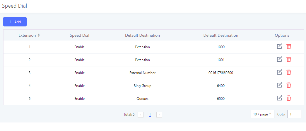
DISA
In many situations, the user will find the need to access his own IPPBX resources, but he is not physically close to any one of his extensions. However, he does have access to his own cell phone. In this case, we can use what is commonly known as DISA (Direct Inward System Access). Under this scenario, the user will be able to call from the outside first, whether it’s using his cell phone, pay phone, regular PSTN and etc, and then call into a SIP trunk or PSTN trunk connected to UCM6510 as it is an internal extension.
The UCM6510 supports DISA to be used in IVR or inbound route. Before using it, create new DISA under Web GUI🡪Call Features🡪DISA.
- Click on “Create New DISA” to add a new DISA.
- Click on to edit the DISA configuration.
- Click on to delete the DISA.
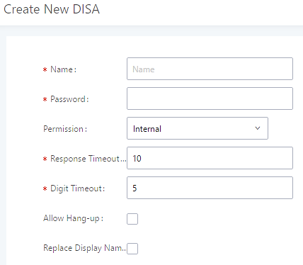
Name | Configure DISA name to identify the DISA. |
Password | Configure the password (digit only) required for the user to enter before using DISA to dial out. Note: The password has to be at least 4 digits. |
Permission | Configure the permission level for DISA. The available permissions are “Internal”, “Local”, “National” and “International” from the lowest level to the highest level. The default setting is “Internal”. If the user tries to dial outbound calls after dialing into the DISA, the UCM6510 will compared the DISA’s permission level with the outbound route’s privilege level. If the DISA’s permission level is higher than (or equal to) the outbound route’s privilege level, the call will be allowed to go through. |
Response Timeout | Configure the maximum amount of time the UCM6510 will wait before hanging up if the user dials an incomplete or invalid number. The default setting is 10 seconds. |
Digit Timeout | Configure the maximum amount of time permitted between digits when the user is typing the extension. The default setting is 5 seconds. |
Allow Hangup | If enabled, during an active call, users can enter the UCM6510 Hangup feature code (*0 by default) to disconnect the call or hang up directly. A new dial tone will be heard shortly for the user to make a new call. The default setting is “No”. |
Replace Display Name | If enabled, the UCM will replace the caller display name with the DISA name. |
Once successfully created, users can configure the inbound route destination as “DISA” or IVR key event as “DISA”. When dialing into DISA, users will be prompted with password first. After entering the correct password, a second dial tone will be heard for the users to dial out.
Emergency
UCM supports configuration and management of numbers to be called in emergency, thus bypassing the regular outbound call routing process and allowing users in critical situation to dial out for emergency help with the possibility to have redundant trunks as point of exit in case one of the lines is down.
UCM6xxx series are also now in full compliance with Kari’s Law and Ray Baum’s Act, for more information, please refer to the following links:
https://www.fcc.gov/mlts-911-requirements
https://documentation.grandstream.com/knowledge-base/emergency-calls/
In addition, Emergency calls can be automatically recorded by toggling on the new Auto Record and recordings can be viewed in the new Emergency Recordings tab on the same page. Additionally, users can have these recordings be sent to the configured email address(es). Email alerts are also supported after enabling the notification for the event under “Maintenance 🡪 System Events”
To configure emergency numbers, users need to follow below steps:
- Navigate on the web GUI under “Call Features 🡪 Emergency Calls”
- Click on
 to add a new emergency number.
 - Configure the required fields “Name, Emergency Number and Trunk(s) to be used to reach the number”.
- Save and apply the configuration.
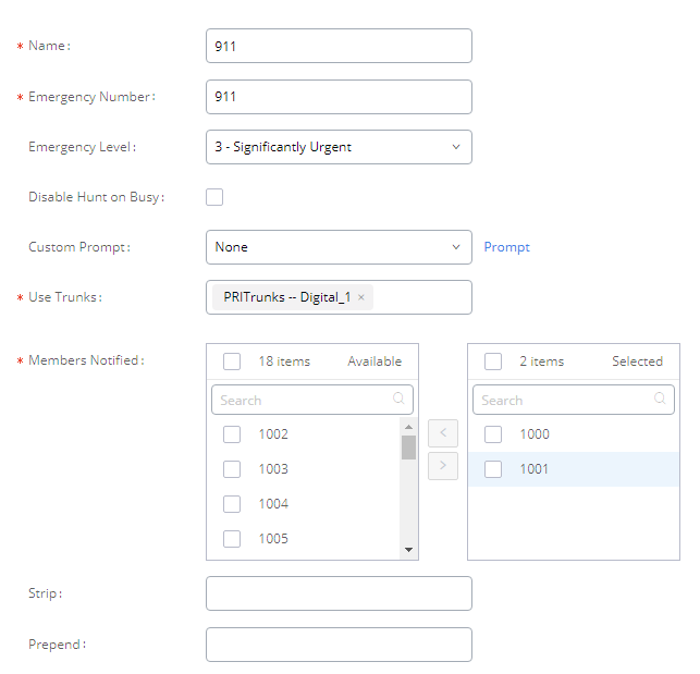
The table below gives more description of the configuration parameters when creating emergency numbers.
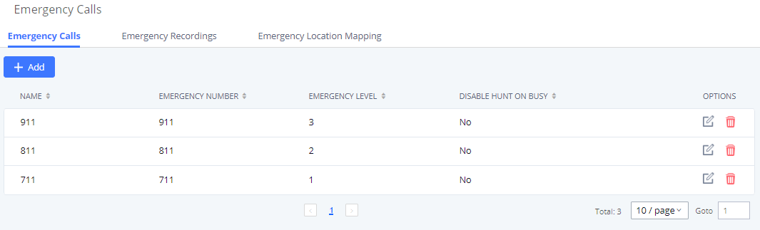
Callback
Callback is designed for users who often use their mobile phones to make long distance or international calls which may have high service charges. The callback feature provides an economic solution for reduce the cost from this.
The callback feature works as follows:
- Configure a new callback on the UCM6510.
- On the UCM6510, configure destination of the inbound route for analog trunk to callback.
- Save and apply the settings.
- The user calls the PSTN number of the UCM6510 using the mobile phone, which goes to callback destination as specified in the inbound route.
- Once the user hears the ringback tone from the mobile phone, hang up the call on the mobile phone.
- The UCM6510 will call back the user.
- The user answers the call.
- The call will be sent to DISA or IVR which directs the user to dial the destination number.
- The user will be connected to the destination number.
In this way, the calls are placed and connected through trunks on the UCM6510 instead of to the mobile phone directly. Therefore, the user will not be charged on mobile phone services for long distance or international calls.
To configure callback on the UCM6510, go to Web GUI🡪Call Features🡪Callback page and click on ![]() . Configuration parameters are listed in the following table.
. Configuration parameters are listed in the following table.
|
Name |
Configure a name to identify the Callback. (Enter at least two characters) |
|
CallerID Pattern |
Configure the pattern of the callers allowed to use this callback. The caller who places the inbound call needs to have the CallerID match this pattern so that the caller can get callback after hanging up the call. Note: If leaving as blank, all numbers are allowed to use this callback. |
|
Outbound Prepend |
Configure the prepend digits to be added at before dialing the outside number. The number with prepended digits will be used to match the outbound route. ‘-’ is the connection character which will be ignored. |
|
Delay Before Callback |
Configure the number of seconds to be delayed before calling back the user. |
|
Destination |
Configure the destination which the callback will direct the caller to. Two destinations are available:
The caller can then enter the desired number to dial out via UCM6510. |
BLF and Event List
BLF
The UCM6510 supports BLF monitoring for extensions, ring group, call queue, conference room and parking lot. For example, on the user’s phone, configure the parking lot number 701 as the BLF monitored number. When there is a parked call on 701, the LED for this BLF key will light up in red, meaning a call is parked against this parking lot. Pressing this BLF key can pick up the call from this parking lot.
Event List
Besides BLF, users can also configure the phones to monitor event list. By using event list, local extensions on the same UCM6510 or remote extensions on the VOIP trunk can be monitored. The event list settings are under Web GUI🡪Call Features🡪Event List.
- Click on “Create New Event List” to add a new event list.
- Sort selected extensions manually in the Eventlist.
- Click on to edit the event list configuration.
- Click on to delete the event list.
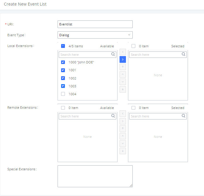
|
URI |
Configure the name of this event list (for example, office_event_list). Please note the URI name cannot be the same as the extension name on the UCM6510. The valid characters are letters, digits, _ and -. |
|
Local Extensions |
Select the available extensions listed on the local UCM6510 to be monitored in the event list. |
|
Remote Extensions |
If LDAP sync is enabled between the UCM6510 and the peer UCM6510, the remote extensions will be listed under “Available Extensions”. If not, manually enter the remote extensions under “Special Extensions” field. |
|
Special Extensions |
Manually enter the remote extensions in the peer/register trunk to be monitored in the event list. Valid format: 5000,5001,9000 |
Event List BLF can be used to monitor remote LDAP extensions on VoIP trunks. SIP endpoints will need to support event list BLF to monitor remote extensions.
When an event list is created on the UCM and remote extensions are added to the list, the UCM will send out SIP SUBSCRIBE to the remote UCM to obtain the remote extension status. When the SIP end points register and subscribe to the local UCM event list, it can obtain the remote extension status from this event list.
Once successfully configured, the event list page will show the status of total extension and subscribers for each event list. Users can also select the event URI to check the monitored extension’s status and the subscribers’ details.
Dial by Name
Dial By Name is a feature on the PBX that allows caller to search a person by first or last name via his/her phone’s keypad. The administrator can define the Dial By Name directory including the desired extensions in the directory and the searching type by “first name” or “last name”. After dialing in, the PBX IVR/Auto Attendant will guide the caller to spell the digits to find the person in the Dial By Name directory. This feature allows customers/clients to use the guided automatic system to contact the enterprise employees without having to know the extension number, which brings convenience and improves business image for the enterprise.
Dial By Name Configuration
The administrators can create the dial by name group under Web GUI🡪Call Features🡪Dial By Name.
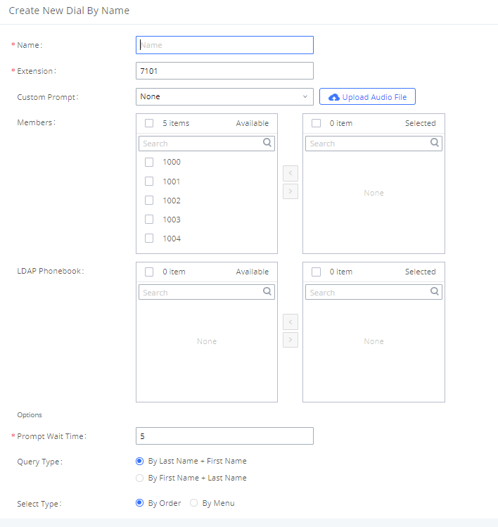
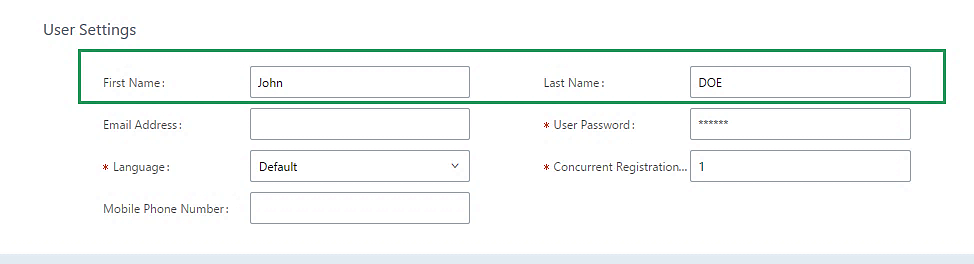
Enter a Name to identify the Dial By Name group.
- Extension
Configure the direct dial extension for the Dial By Name group.
This option sets a custom prompt for directory to announce to a caller. The file can be uploaded from the page “Custom Prompt”. Click “Upload Audio File” to add additional record.
- Available Extensions/Selected Extensions
Select available extensions from the left side to the right side as the directory for the Dial By Name group. Only the selected extensions here can be reached by the Dial By Name IVR when dialing into this group. The extensions here must have a valid first name and last name configured under Web GUI🡪Extension/Trunk🡪Extensions in order to be searchable in Dial By Name directory through IVR. By specifying the extensions here, the administrators can make sure unscreened calls will not reach the company employee if he/she does not want to receive them directly.
- Prompt Wait Time
Configure “Prompt Wait Time” for Dial By Name feature. During Dial By Name call, the caller will need to input the first letters of First/Last name before this wait time is reached. Otherwise, timeout will occur, and the call might hang up. The timeout range is between 3 and 60 seconds.
- Query Type
Specify the query type. This defines how the caller will need to enter to search the directory.
By First Name: enter the first 3 digits of the first name to search the directory.
By Last Name: enter the first 3 digits of the last name to search the directory.
By Full Name: enter the first 3 digits of the first name or last name to search the directory.
- Select Type
Specify the select type on the searching result. The IVR will confirm the name/number for the party the caller would like to reach before dialing out.
By Order: After the caller enters the digits, the IVR will announce the first matching party’s name and number. The caller can confirm and dial out if it is the destination party, or press * to listen to the next matching result if it is not the desired party to call.
By Menu: After the caller enters the digits, the IVR will announce 8 matching results. The caller can press number 1 to 8 to select and call or press 9 for results in next page.
The Dial By Name group can be used as the destination for inbound route and key pressing event for IVR. The group name defined here will show up in the destination list when configuring IVR and inbound route. If Dial By Name is set as a key pressing event for IVR, users can dial star (*) toto exit from Dial By Name, and re-enter the IVR to start a new event. The following example shows how to use this option.
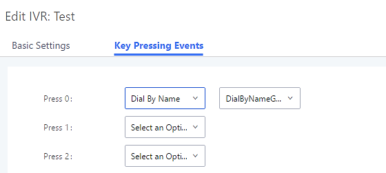
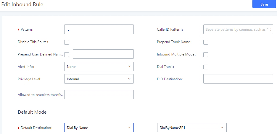
Username Prompt Customization
Starting from fw 1.0.15.x, the Dial By Name feature can use the recorded name prompt of a user to announce his/her name assigned to the dialed extension. If no name prompt greeting exists, the name will be spelt out like in previous versions.
There are two ways to customize/set new username prompt for an extension:
Upload Username Prompt File from Web GUI
- First, Users should have a pre-recorded file respecting the following format:
- PCM encoded / 16 bits / 8000Hz mono.
- In .GSM or .WAV format.
- File size under 5MB.
- Filename must be set as the extension number. For example, the recorded file name 1000.wav will be used for extension 1000.
- Go under web GUI PBX Settings 🡪 Voice Prompt 🡪 Username Prompt and click on button.
- Select the recorded file to upload it and press Save and Apply Settings.
- Click on
 to record again the username prompt.
 - Click on to play recorded username prompt.
- Select username prompts and press to delete specific file or select multiple files for deletion using the button
 .
.
Record Username via Voicemail Menu
Users can also record their username via the voicemail menu:
- Dial *97 or *98 to access the voicemail menu. If *98 is dialed, enter the desired extension and voicemail password.
- Upon entering the extension’s voicemail system, dial 0 to enter the recordings menu.
- Press 3 to start recording the username.
Active Calls and Monitor
The active calls on the UCM6510 are displayed in Web GUI🡪System Status🡪Active Calls page. Users can monitor call status, hang up active call(s) as well as barge in active call(s) in real time manner.
Active Calls Status
To view the status of active calls, navigate to Web GUI🡪System Status🡪Active Calls. The following figure shows extension 1000 is calling 1001. 1001 is ringing.
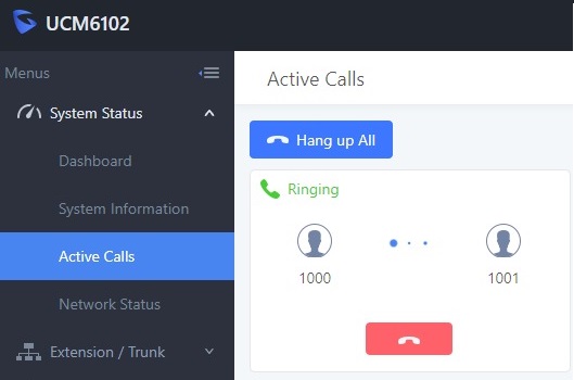
The following figure shows the call between 1002 and 1003 is established.
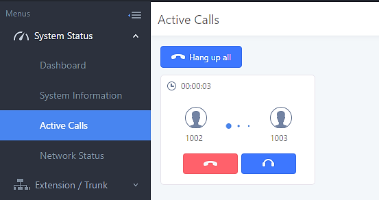
The black color of the active call means the connection of call time is less than half an hour. It means this call is normal.

The yellow color of the active call means the connection of call time is greater than half an hour but less than one hour. It means this call is a bit long.
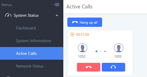
The red color of the active call means the connection of call time is more than one hour. It means this call could be abnormal.
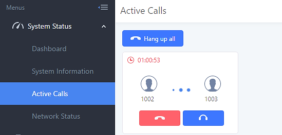
Hang Up Active Calls
To hang up an active call, click on ![]() icon in the active call dialog. Users can also click on
icon in the active call dialog. Users can also click on ![]() to hang up all active calls shown on the Active Calls page.
to hang up all active calls shown on the Active Calls page.
Call Monitor
During an active call, click on icon ![]() and the Monitor dialog will pop up.
and the Monitor dialog will pop up.
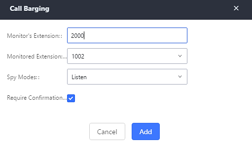
In the “Monitor” dialog, configure the following to monitor an active call:
- Enter an available extension for “Monitor’s Extension” which will be used to monitor the active call.
- “Monitored Extension” must be one of the parties in the active call to be monitored.
- Select spy mode. There are three options in “Spy Mode”.
- Listen
In “Listen” mode, the extension monitoring the call can hear both parties in the active call but the audio of the user on this extension will not be heard by either party in the monitored active call.
- Whisper
In “Whisper” mode, the extension monitoring the call can hear both parties in the active call. The user on this extension can only talk to the selected monitored extension and he/she will not be heard by the other party in the active call. This can be usually used to supervise calls.
- Barge
In “Barge” mode, the extension monitoring the call can talk to both parties in the active call. The call will be established similar to three-way conference.
- Enable or disable “Require Confirmation” option. If enabled, the confirmation of the invited monitor’s extension is required before the active call can be monitored. This option can be used to avoid adding participant who has auto-answer configured or call forwarded to voicemail.
- Click on “Add”. An INVITE will be sent to the monitor’s extension. The monitor can answer the call and start monitoring. If “Require Confirmation” is enabled, the user will be asked to confirm to monitor the call.
Another way to monitor active calls is to dial the corresponding feature codes from an extension. Please refer to [Table 105: UCM6510 Feature Codes] and [Call Recording] section for instructions.
Call Features Codes
The UCM6510 supports call recording, transfer, call forward, call park and other call features via feature code. Feature Codes settings can be found at Web GUI🡪Call Features🡪Feature Codes. This section lists all the feature codes in the UCM6510 and describes how to use the call features.
Feature Codes
|
Feature Maps | |
|
Blind Transfer |
Disable Allow Caller: Enable the feature code on caller side only. Allow Callee: Enable the feature code on callee side only. Allow Both: Enable the feature code on both caller and callee. |
|
Attended Transfer |
Disable Allow Caller: Enable the feature code on caller side only. Allow Callee: Enable the feature code on callee side only. Allow Both: Enable the feature code on both caller and callee. |
|
Seamless Transfer |
|
|
Disconnect |
Disable Allow Caller: Enable the feature code on caller side only. Allow Callee: Enable the feature code on callee side only. Allow Both: Enable the feature code on both caller and callee. |
|
Call Park |
Disable Allow Caller: Enable the feature code on caller side only. Allow Callee: Enable the feature code on callee side only. Allow Both: Enable the feature code on both caller and callee. |
|
Start/Stop Call Recording |
Disable Allow Caller: Enable the feature code on caller side only. Allow Callee: Enable the feature code on callee side only. Allow Both: Enable the feature code on both caller and callee. |
|
Feature Code Digits Timeout |
Set the maximum interval (ms) between digits for feature code activation |
|
DND/Call Forward | |
|
Do Not Disturb (DND) Activate |
|
|
Do Not Disturb (DND) Deactivate |
|
|
Call Forward Busy Activate |
|
|
Call Forward Busy Deactivate |
|
|
Call Forward No Answer Activate |
|
|
Call Forward No Answer Deactivate |
|
|
Call Forward Unconditional Activate |
|
|
Call Forward Unconditional Deactivate |
|
| |
|
Remote Call Forward Busy Enable |
|
|
Remote Call Forward Busy Disable |
|
|
Remote Call Forward No Answer Enable |
|
|
Remote Call Forward No Answer Disable |
|
|
Remote Call Forward Unconditional Enable |
|
|
Remote Call Forward Unconditional Disable |
|
|
Remote Call Forward Whitelist |
Only the Extensions selected in this whitelist can configure call forwarding for any extension via feature codes. |
|
Feature Codes | |
|
Voicemail Access Code |
|
|
My Voicemail |
|
|
Agent Pause |
|
|
Agent Unpause |
|
|
Paging Prefix |
|
|
Intercom Prefix |
|
|
Blacklist Add |
|
|
Blacklist Remove |
|
|
Call Pickup on Ringing |
|
|
Pickup In-call |
|
|
Pickup Extension |
|
|
Direct Dial Voicemail Prefix |
|
|
Direct Dial Mobile Phone Prefix |
|
|
Call Completion Request |
|
|
Call Completion Cancel |
|
|
Enable Spy |
Check this box to enable spy feature codes. Disabled by default. |
|
Listen Spy |
|
|
Whisper Spy |
|
|
Barge Spy |
|
|
Wakeup Service |
|
|
PMS Wakeup Service |
|
|
Update PMS Room Status |
|
|
Presence Status |
1:”unavailable” 2:”available” 3:”away” 4:”chat 5:”dnd 6:”userdef” |
|
Dynamic Agent Logout |
|
|
Voicemail Group Access Code |
Call voicemail group access code to access group voicemail. If password is required, enter password followed by pound “#” key. |
The UCM6510 also allows user to enable / disable specific feature code by one click. As shown below:
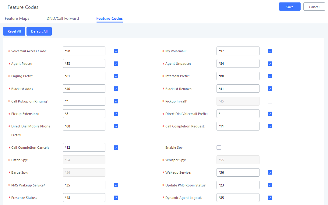
Parking Lot
User can create parking lots and their related slots under Web GUI🡪 Call Features🡪 Parking Lot. In the Parking Lot page, users can create lots of their own. This allows different groups within an organization to have their own parking lots instead of sharing one large parking lot with others. While creating a new parking lot, users can assign it a range that they think is appropriate for the group that will use the parking lot.
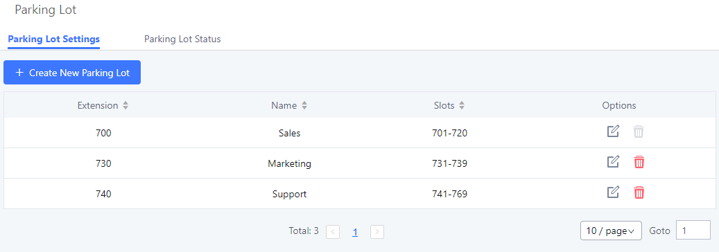
User can create a new Parking lot by clicking on button “Create New Parking Lot” ![]() :
:
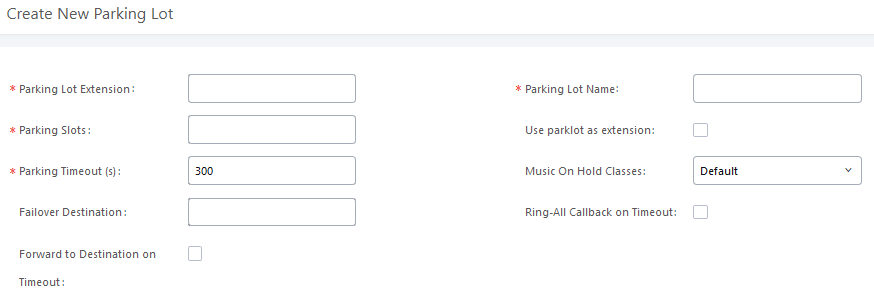
|
Parking Lot Extension |
|
|
Parking Lot Name |
|
|
Parked Slots |
|
|
Use Parklot as Extension |
|
| |
|
Music On Hold Playlist |
Select the Music on Hold Playlist. |
|
Configures a callback failover destination when the extension that is called back is busy. The call will be routed to the destination number and this reduces the chance of dropping parked calls. Note: This field cannot exceed 32 characters. | |
|
If enabled, all registered endpoints of the extension will ring when callback occurs. Otherwise, the original endpoint will be called back. Note: This option will not be available if Forward to Destination on Timeout is enabled. | |
|
Forward to destination on timeout |
If enabled, the call will be routed to the configured destination upon timeout. Otherwise, the call will be routed back to the original caller. |
|
Timeout Destination |
This option appears once Forward to Destination on Timeout is enabled. Upon park timeout, the call will be routed to the configured destination. |
Call Park
The UCM6510 provides call park and call pickup features via feature code.
Park a Call
There are two feature codes that can be used to park the call.
- Feature Maps🡪Call Park (Default code #72)
During an active call, press #72 and the call will be parked. Parking lot number (default range 701 to 720) will be announced after parking the call.
- Feature Misc🡪Call Park (Default code 700)
During an active call, initiate blind transfer (default code #1) and then dial 700 to park the call. Parking lot number (default range 701 to 720) will be announced after parking the call.
Retrieve Parked Call
To retrieve the parked call, simply dial the parking lot number and the call will be established. If a parked call is not retrieved before timeout, the original extension who parks the call will be called back.
Monitor Call Park CID Name Information (GXP21xx Phones Only)
Users can see the CID name information of parked calls. VPK/MPKs must be configured as “Monitored Call Park” with the desired parking lot extension. The display will alternate between displaying the parking lot extension and the call’s CID name. There is no need to configure anything on the UCM.
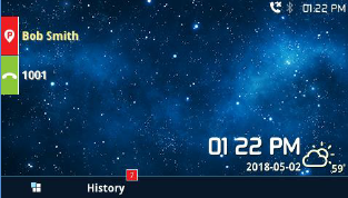
Call Recording
The UCM6510 allows users to record audio during the call. If “Auto Record” is turned on for extension or trunk, the call will be automatically recorded when there is established call with the extension or trunk. Otherwise, please follow the instructions below to manually record the call.
- Make sure the feature code for “Start/Stop Call Recording” is configured and enabled.
- After establishing the call, enter the “Start/Stop Call Recording” feature code (by default *3) followed by # or SEND to start recording.
- To stop the recording, enter the “Start/Stop Call Recording” feature code (by default *3) followed by # or SEND again. Or the recording will be stopped once the call hangs up.
- The recording file can be retrieved under Web GUI🡪CDR. Click on to show and play the recording or click on to download the recording file.
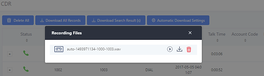
The above recorded call’s recording files are also listed under the UCM6510 Web GUI🡪CDR🡪Recording Files.
Enable Spy
If “Enable Spy” option is enabled, feature codes for Listen Spy, Whisper Spy and Barge Spy are available for users to dial from any extension to perform the corresponding actions.
Assume a call is on-going between extension A and extension B, user could dial the feature code from extension C to listen on their call (*54 by default), whisper to one side (*55 by default), or barge into the call (*56 by default). Then the user will be asked to enter the number to call, which should be either side of the active call, extension A or B in this example.
Shared Call Appearance (SCA)
Shared Call Appearance (SCA) functionality has been added to the UCM. With SCA, users can assign multiple devices to one extension, configure endpoints to monitor that extension, make actions on behalf of that extension such as viewing call status and placing and receiving calls, and even barging into existing calls. To configure the SCA functionality, please follow the steps below:
- Users can enable SCA by navigating to the Extensions page, editing the desired extension, and enabling the option SCA.
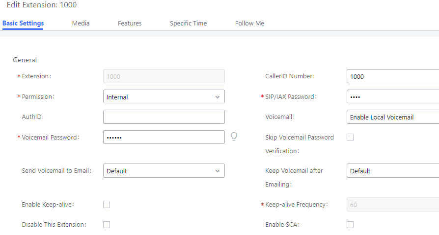
- After enabling the option, navigate to Call Features🡪SCA. The newly enabled SCA extension will be listed. Click the “+” button under the Options column to add a number that will share the main extension’s call appearance, which will be called private numbers.
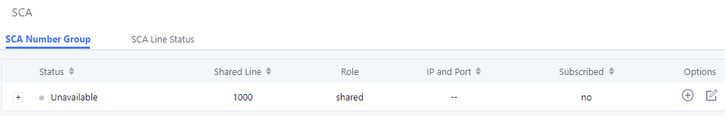
- Configure the private number as desired.
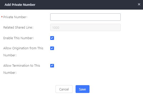
- Once the private number has been created, users must now register a device to it. To properly register a device to the private number, use the configured private number as the SIP User ID. Auth ID and Password will be the same as the main extension’s. Once registration is complete, SCA is now configured.
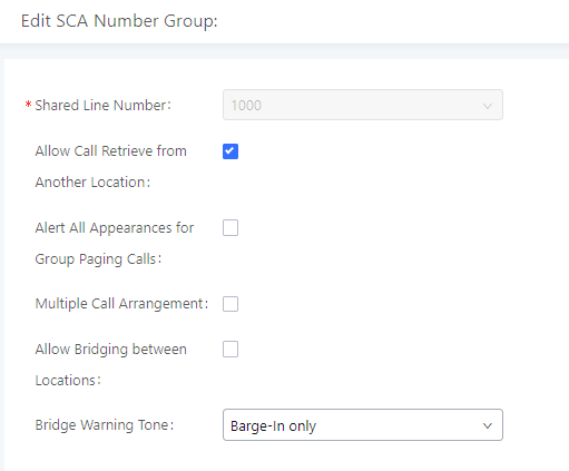
SCA has various options to change its behavior :
- Allow Call Retrieve from Another Location – Allows users to retrieve held calls using any device associated with the SCA extension.
- Alert All Appearances for Group Paging Calls – Alerts all devices associated with the SCA extension.
- Multiple Call Arrangement – Allows all devices associated with the SCA extension to make different calls at the same time.
- Allow Bridging between Locations – Allows devices associated with the SCA extension to barge into existing calls of the same SCA group.
- Bridge Warning Tone – Notification sound that will play when a party barges into the call. Three options are available :
- None – No notification sound will play
- Barge-In Only – The notification sound will play once when a party barges in.
- Barge-In and Repeat – The notification sound will play when a party barges in and will play again after every 30 seconds.
- Next, configure the VPK or MPK to Shared for both the main extension and the private number. SCA is now configured for both endpoint devices.
The following table describes the SCA Number configuration setting:
|
Private Number |
Configures the private number for the SCA. |
|
Related Shared Line |
Display the related shared line. |
|
Enable This Number |
Enables/disables the private number. |
|
Allow Origination from This Number |
Enabling this option will allow calling from this private number. By default, it is enabled. |
|
Allow Termination to This Number |
Enabling this option will allows calls to this private number. By default, it is enabled. |
The following table describes the options available when editing the SCA number:
|
Shared Line Number |
While SCA is enabled, this number will be the same as the extension number. |
|
Allow Call Retrieve from Another Location |
Allows remote call retrieval. Must be enabled in public hold. By default, it is enabled. |
|
Alert All Appearances for Group Paging Calls |
Allows all SCA group members to ring when the SCA shared number is paged. If disabled, only the SCA shared number will ring when paged. By default, it is disabled. |
|
Multiple Call Arrangement |
Allows simultaneous calls in an SCA group. By default, it is disabled. |
|
Allow Bridging between Locations |
Allows location bridging for SCA group. Must be enabled when using the Barge-In feature. By default, it is disabled. |
|
Bridge Warning Tone |
Configures the notification in the bridge when another party join.
By default, it is set to “Barge-In Only”. |
Announcement
The Announcement feature (not to be confused with Announcement Paging and Announcement Center) is a feature that allows users to set an unskippable audio file to play to callers before routing them to a configured destination. Announcements can be configured as a destination in the [Inbound Routes] or in [IVR].
To configure the Announcement, users need to follow below steps:
- Navigate on the web GUI under “Call Features 🡪 Announcement”
- Click on to add a new Announcement.
- Configure the required fields Name, Prompt, Default Destination to be used for the announcement.
- Save and apply the configuration.
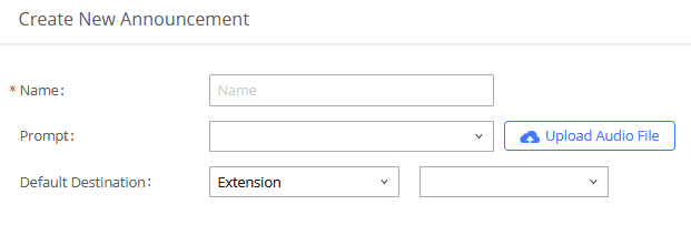
The table below gives more description of the configuration parameters when creating Announcement.
|
Name |
Configure the name of the Announcement. Note: Please use letters, digits, _ or – only and no more than 64 characters. |
|
Prompt |
Audio file that will be played before ringing the configured default destination. Note: Sound file must be PCM encoded, 16 bits at 8000Hz mono in mp3/wav format or raw ulaw/alaw/gsm file with .mp3/.wav/.ulaw/.alaw/.gsm suffix. The file size must be less than 5MB. If uploading a compressed file, the file must have .tar/.tgz/.tar.gz suffix. the file name must contain only letters, numbers or special characters -_. The file size must be less than 30MB. Filename cannot exceed 100 characters. |
|
Default Destination |
Select the destination where to send the call after playing the announcement. The available default destinations are:
|
Created Announcements will be listed as shown below:
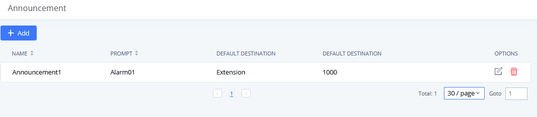
- Press
 to edit the announcement.
 - Press
 to delete the announcement.
PBX Settings
This section describes internal options that have not been mentioned in previous sections yet. The settings in this section can be applied globally to the UCM6510, including general configurations, jitter buffer, RTP settings, hardware config and STUN monitor. The options can be accessed via Web GUI🡪PBX Settings🡪General Settings.
General Settings
|
General Preferences | |
|
Global Outbound CID |
Configure the global CallerID used for all outbound calls when no other CallerID is defined with higher priority. If no CallerID is defined for extension or trunk, the global outbound CID will be used as CallerID. |
|
Global Outbound CID Name |
Configure the global CallerID Name used for all outbound calls. If configured, all outbound calls will have the CallerID Name set to this name. If not, the extension’s CallerID Name will be used. |
|
Ring Timeout |
Configure the number of seconds to ring an extension before the call goes to the user’s voicemail box. The default setting is 60. Note: This is the global value used for each extension if “Ring Timeout” field is left empty on the extension configuration page. |
|
Call Duration Limit |
Configure the maximum duration of call-blocking. |
|
Record Prompt |
If enabled, users will hear voice prompt before recording is started or stopped. For example, before recording, the UCM6510 will play voice prompt “The call will be recorded”. The default setting is “No”. |
|
Enable 486 to Failover Trunk |
Reroutes failed outbound calls that receive a 486 response through the failover trunk to retry the call. If disabled, calls that receive a 486 response will be terminated. |
|
Enter a name to identify the UCM. The name will be displayed on UCM web interface. | |
|
Configure the International prefix. Default is 00. If empty, international call prefix can be empty or +. This parameter helps the UCM to identify the international call prefix for the country (00, 011, 810…) to avoid any conflict when using blacklist for specific countries. When outbound blacklist is enabled, UCM will apply the following rule “International Call Prefix+Country Code+Destination number”. When making outbound call, UCM will check “International Call Prefix” then “Country Code”, if the combination exists in the blacklist, then the call will fail, otherwise, the call will be authorized. For example: If blacklist is selecting countries with prefix code 001, dialing a number like 00123456789 will be blocked even if the number is not part of blacklisted countries if “International Call Prefix” is not set. While in same example, if “International Call Prefix” is set to “00”, UCM will allow the dialed number. | |
|
Extension Preferences | |
|
Enforce Strong Password |
If enabled, strong password will be enforced for the password created on the UCM6510. The default setting is enabled. Strong Password Rules:
Repetitive digits pattern (such as 0000, 1111, 1234, 2345, and etc), or common digits’ pattern (such as 111222, 321321 and etc) are not allowed to be configured as password.
|
|
Enable Random Password |
If enabled, random password will be generated when the extension is created. The default setting is “Yes”. It is recommended to enable it for security purpose. |
|
Enable Auto E-mail Notification |
If enabled, UCM6510 will send Email notification to user automatically after editing extension settings or adding a new extension. |
|
Disable Extension Range |
If set to “Yes”, users could disable the extension range pre-configured/configured on the UCM6510. The default setting is “No”. The default extension range assignment is shown in “Extension Ranges” below. Note: While there are no issues with disabling extension ranges, system administrators will need to manage extensions to avoid extension conflicts. |
|
Extension Ranges |
The default extension range assignment is:
User Extensions is referring to the extensions created under Web GUI🡪Extension/Trunk🡪Extensions page.
This refers to the extensions that can be manually picked from end device when being provisioned by the UCM6510. There are two related options in zero config page🡪Auto Provision Settings, “Pick Extension Segment” and “Enable Pick Extension”. If “Enable Pick Extension” under zero config settings is selected, the extension list defined in “Pick Extension Segment” will be sent out to the device after receiving the device’s request. This “Pick Extension Segment” should be a subset of the “Pick Extensions” range here. This feature is for the GXP series phones that support selecting extension to be provisioned via phone’s LCD.
This sets the range for “Zero Config Extension Segment” which is the extensions can be assigned on the UCM6510 to provision the end device.
|
Call Failure Tone Settings
SIP Trunk Prompt Tone
Prompt Tone Settings tab has been added to the UCM to help users choose which prompt will be played by the UCM during call failure, the following voice message responses have been added and can be set to be played for 4XX, 5XX, and 6XX call failures:
- Default for 404 and 604 status codes: “Your call can’t be completed as dialed. Please check the number and dial again.”
- Default for 5xx status codes: “Server error. Please check your device.”
- Default for 403 and 603 status codes: “The call was rejected by the server. Please try again later.”
- Default for all other status codes: “All circuits are busy now. Please try again later.”
Additionally, custom voice messages recorded and uploaded in PBX Settings🡪Voice Prompt🡪Custom Prompt can be used for these failure responses instead of the default messages.
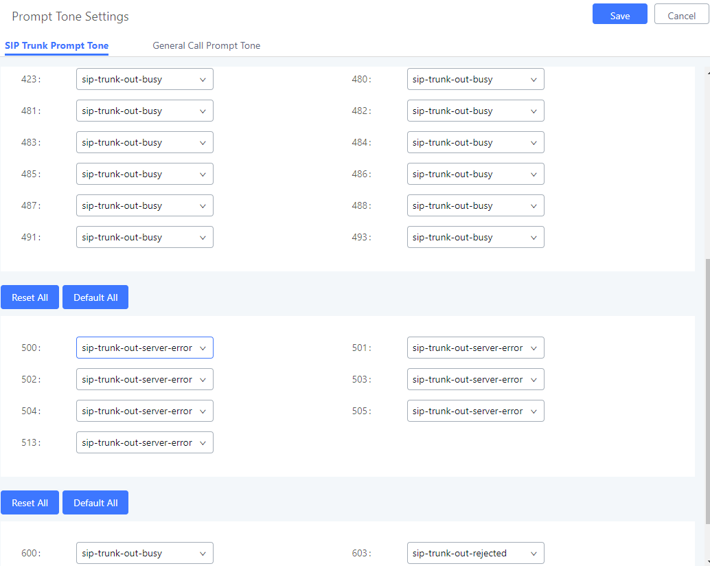
General Call Failure Tone
Moreover, users also have the possibility to customize the prompt for typical call failure reasons like (no permission to allow outbound calls, busy lines, incorrect number dialed …Etc).
To customize these prompts user could record and upload their own files under “’PBX Settings 🡪 Voice Prompt 🡪 Custom Prompts” then select each one for specific call failure case under “PBX Settings -> Prompt Tone Settings 🡪 General Call Prompt Tone” page as shown on the following figure:
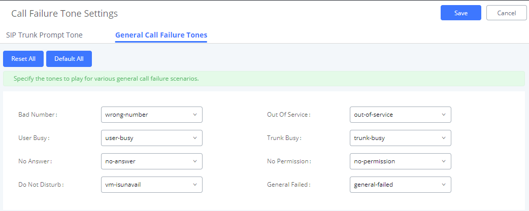
PBX Settings/Jitter Buffer
|
SIP Jitter Buffer | |
|
Enable Jitter Buffer |
Select to enable jitter buffer on the sending side of the SIP channel. The default setting is “No”. |
|
Jitter Buffer Size |
Configure the time (in ms) to buffer. This is the jitter buffer size used in “Fixed” jitter buffer or used as the initial time for “adaptive” jitter buffer. The default setting is 100. |
|
Max Jitter Buffer |
Configure the maximum time (in ms) to buffer for “Adaptive” jitter buffer implementation or used as the jitter buffer size for “Fixed” jitter buffer implementation. The default setting is 200. |
|
Implementation |
Configure the jitter buffer implementation on the sending side of a SIP channel. The default setting is “Fixed”.
The size is always equal to the value of “Max Jitter Buffer”.
The size is adjusted automatically and the maximum value equals to the value of “Max Jitter Buffer”. |
PBX Settings/RTP Settings
RTP Settings
|
RTP Start |
Configure the RTP port starting number. The default setting is 10000. |
|
RTP End |
Configure the RTP port ending address. The default setting is 20000. |
|
Strict RTP |
Configure to enable or disable strict RTP protection. If enabled, RTP packets that do not come from the source of the RTP stream will be dropped. The default setting is “Disable”. |
|
RTP Checksums |
Configure to enable or disable RTP Checksums on RTP traffic. The default setting is “Disable”. |
|
ICE Support |
Configure whether to support ICE, ICE is the integrated use of STUN and TURN structure to provide reliable VoIP or video calls and media transmission, via a SIP request/ response model or multiple candidate endpoints exchanging IP addresses and ports, such as private addresses and TURN server address. It is enabled by default. |
|
TURN Server |
Configure TURN server address. TURN is an enhanced version of the STUN protocol and is dedicated to the processing of symmetric NAT problems. |
|
TURN Server Name |
Configure turn server account name. |
|
TURN Server Password |
Configure turn server account password. |
|
STUN Server |
Configure STUN server address, STUN protocol is a Client / Server – is also a Request / Response protocol, where it is used to check the connectivity between the two terminals, such as maintaining NAT binding entries keep alive agreement. The default STUN Server is stun.ipvideotalk.com Valid format: [(hostname | IP-address) [‘:’ port] The default port number is 3478 if not specified. |
Payload
The UCM6510 payload type for audio codecs and video codes can be configured here.
|
AAL2-G.726 |
Configure payload type for ADPCM (G.726, 32kbps, AAL2 codeword packing). The default setting is 112. |
|
DTMF |
Configured payload type for DTMF. The default setting is 101. |
|
G.721 Compatible |
Configure to enable/disable G.721 compatible. The default setting is Yes. |
|
G.726 |
Configure the payload type for G.726 if “G.721 Compatible” is disabled. The default setting is 111. |
|
iLBC |
Configure the payload type for iLBC. The default setting is 97. |
|
H.264 |
Configure the payload type for H.264. The default setting is 99. |
|
H.263P |
Configure the payload type for H.263+. The default setting is 100 103. |
|
VP8 |
Configure the payload type for VP8. The default setting is 108. |
|
Main Video FEC |
Configure the payload type for Main Video FEC, The default is 120 |
|
RTP FECC |
Configure the payload type for RTP FECC, The default is 125 |
|
RTX |
Configure the payload type for RTX, The default is 124 |
PBX Settings/NAS
UCM supports saving call recordings and backing up/restoring system backups to a NAS server. The following options are available:
|
Enable |
Toggles the NAS recording functionality. |
|
Host |
Configure the Domain or IP address of the NAS server. Note: Currently, only IP addresses are supported in the Host/IP field. |
|
Share Name |
Specify the name of the shared folder. |
|
Username |
Specify the account username to access the NAS server. |
|
Password |
Configure the account password to access the NAS server. |
|
Status |
If configured correctly, the Status field will show “Mounted”, and the newly added NAS server will be shown on the Mounted Netdisk List. Additionally, the NAS will appear as a selectable storage option in the PBX Settings->Recording Storage page and CDR🡪Recording Files page. |
IAX Settings
The UCM6510 IAX global settings can be accessed via Web GUI🡪PBX🡪IAX Settings.
IAX Settings/General
|
Bind Port |
Configure the port number that the IAX2 will be allowed to listen to. The default setting is 4569. |
|
Bind Address |
Configure the address that the IAX2 will be forced to bind to. The default setting is 0.0.0.0, which means all addresses. |
|
IAX1 Compatibility |
Select to configure IAX1 compatibility. The default setting is “No”. |
|
No Checksums |
If selected, UDP checksums will be disabled and no checksums will be calculated/checked on systems supporting this feature. The default setting is “No”. |
|
Delay Reject |
If enabled, the IAX2 will delay the rejection of calls to avoid DOS. The default setting is “No”. |
|
ADSI |
Select to enable ADSI phone compatibility. The default setting is “No”. |
|
Music On Hold Interpret |
Specify which Music On Hold playlist this channel would like to listen to when being put on hold. This music playlist is only effective if this channel has no music playlist configured and the bridged channel putting the call on hold has no “Music On Hold Suggest” setting. |
|
Music On Hold Suggest |
Specify which Music On Hold playlist to suggest to the bridged channel when putting the call on hold. |
|
Bandwidth |
Configure the bandwidth for IAX settings. The default setting is “Low”. |
IAX Settings/Registration
|
IAX Registration Options | |
|
Min Reg Expire |
Configure the minimum period (in seconds) of registration. The default setting is 60. |
|
Max Reg Expire |
Configure the maximum period (in seconds) of registration. The default setting is 3600. |
|
IAX Thread Count |
Configure the number of IAX helper threads. The default setting is 10. |
|
IAX Max Thread Count |
Configure the maximum number of IAX threads allowed. The default setting is 100. |
|
Auto Kill |
If set to “yes”, the connection will be terminated if ACK for the NEW message is not received within 2000ms. Users could also specify number (in milliseconds) in addition to “yes” and “no”. The default setting is “yes”. |
|
Authentication Debugging |
If enabled, authentication traffic in debugging will not show. The default setting is “No”. |
|
Codec Priority |
Configure codec negotiation priority. The default setting is “Reqonly”.
Consider the callers preferred order ahead of the host’s.
Consider the host’s preferred order ahead of the caller’s.
Disable the consideration of codec preference all together.
This is almost the same as “Disabled”, except when the requested format is not available. The call will only be accepted if the requested format is available. |
|
Type of Service |
Configure ToS bit for preferred IP routing. |
|
IAX Trunk Options | |
|
Trunk Frequency |
Configure the frequency of trunk frames (in milliseconds). The default setting is 20. |
|
Trunk Time Stamps |
If enabled, time stamps will be attached to trunk frames. The default setting is “No”. |
IAX Settings/Security
|
Call Token Optional |
Enter a single IP address or a range of IP addresses for which call token validation is not required. For example: 11.11.11.11 11.11.11.11/22.22.22.22. |
|
Max Call Numbers |
Configure the maximum number of calls allowed for a single IP address. |
|
Max Unvalidated Call Numbers |
Configure the maximum number of Unvalidated calls for all IP addresses. |
|
Call Number Limits |
Configure to limit the number of calls for a give IP address of IP range. |
|
IP or IP Range |
Enter the IP address or a range of IP addresses to be considered for call number limits. For example: 11.11.11.11 11.11.11.11/22.22.22.22. |
SIP Settings
The UCM6510 SIP global settings can be accessed via Web GUI🡪PBX Settings🡪SIP Settings.
SIP Settings/General
Realm For Digest Authentication | Configure the host name or domain name for the UCM6510. Realms MUST be globally unique according to RFC3261. The default setting is Grandstream. Note: Both FQDN and IP address are supported on this field. |
Bind UDP Port | Configure the UDP port used for SIP. The default setting is 5060. |
Bind IP Address | Configure the IP address to bind to. The default setting is 0.0.0.0, which means binding to all addresses. |
Allow Transfer | If set to "No", all transfers initiated by the endpoint in the UCM6510 will be disabled (unless enabled in peers or users). The default setting is "Yes |
MWI From | When sending MWI NOTIFY requests, this value will be used in the "From:" header as the "name" field. If no "From User" is configured, the "user" field of the URI in the "From:" header will be filled with this value. |
Enable Diversion Header | If disabled, the UCM will not forward the diversion header. Note: Diversion header will be included for forwarding and transfer when the option is enabled. The header will also contain public IP information |
Block Collect Calls | If enabled, collect calls will be blocked. Note: Collect calls are indicated by the header "P-Asserted-Service-Info: service-code=Backward Collect Call, P-Asserted-Service-Info: service-code=Collect Call". |
SIP Settings/Misc
Video | |
Max Bit Rate (kb/s) | Configure the maximum bit rate (in kb/s) for video calls. The default setting is 384. |
Support SIP Video | Select to enable video support in SIP calls. The default setting is “Yes”. |
Reject Non-Matching INVITE | If enabled, when rejecting an incoming INVITE or REGISTER request, the IPPBX will always reject with “401 Unauthorized” instead of notifying the requester whether there is a matching user or peer for the request. This reduces the ability of an attacker to scan for valid SIP usernames. The default setting is “No”. |
SDP Attribute Passthrough | |
Enable Attribute Passthrough | If enabled, call negotiation will use final response SDP. |
Early Media | |
Enable Use of Final SDP | If enabled, call negotiation will use final response SDP. |
Ignore 180 Response | If enabled, ignore the ringing indication if has sent 183 response. |
Blind Transfer | |
Allow callback when blind transfer fails | If enabled, the IPPBX will call back to the transferrer when blind transfer fails (due to the destination being busy or not answering. Note: This feature applies only to internal calls.). Note: This feature takes effect only on internal calls. |
Blind transfer timeout | Configure the amount of time in seconds that the transferred party will wait for the destination to answer before being redirected back to the transferrer. Default is 60 seconds. |
DNS | |
DNS mode | This option affects the DNS query only during Calls. When you choose A&AAAA, IPPBX will do both A and AAAA type DNS query; when you chose A, IPPBX will only do A type DNS query; and when you chose AAAA, IPPBX will only do AAAA type DNS query. |
Hold | |
Forward HOLD Requests | Configure the IPPBX to forward HOLD requests instead of processing holds internally. This serves to meet the standards set by some providers that require HOLD requests to be passed along from endpoint to endpoint. This option is disabled by default. Note: Enabling this option may cause hold retrieval issues and MOH to not be heard. |
SIP Settings/Session Timer
|
If checked, always request and run session timer. | |
|
Timer |
If checked, run session timer only when requested by other UA. |
|
Session Expire |
Configure the maximum session refresh interval (in seconds). The default setting is 1800. |
|
Min SE |
Configure the minimum session refresh interval (in seconds). The default setting is 90. |
SIP Settings/TCP and TLS
|
TCP Enable |
Configure to allow incoming TCP connections with the UCM6510. The default setting is “No”. |
|
TCP Bind Address |
Configure the IP address for TCP server to bind to. 0.0.0.0 means binding to all interfaces. The port number is optional. If not specified, 5060 will be used. |
|
TLS Enable |
Configure to allow incoming TLS connections with the UCM6510. The default setting is “No”. |
|
TLS Bind Address |
Configure the IP address for TLS server to bind to. 0.0.0.0 means binding to all interfaces. The port number is optional. If not specified, 5061 will be used. Note: The IP address must match the common name (hostname) in the certificate. Please do not bind a TLS socket to multiple IP addresses. For details on how to construct a certificate for SIP, please refer to the following document: |
|
TLS Do Not Verify |
If enabled, the TLS server’s certificate will not be verified when acting as a client. The default setting is “Yes”. |
|
This is the CA certificate if the TLS server being connected to requires self-signed certificate, including server’s public key. This file will be renamed as “TLS.ca” automatically. Note: The size of the uploaded ca file must be under 2MB. | |
|
TLS Cert |
This is the Certificate file (*.pem format only) used for TLS connections. It contains private key for client and signed certificate for the server. This file will be renamed as “TLS.pem” automatically. Note: The size of the uploaded certificate file must be under 2MB. |
|
TLS CA Cert |
This file must be named with the CA subject name hash value. It contains CA’s (Certificate Authority) public key, which is used to verify the accessed servers. Note: The size of the uploaded CA certificate file must be under 2MB. |
|
TLS CA List |
Display a list of files under the CA Cert directory. |
SIP Settings/NAT
|
External Host |
Configure a static IP address and port (optional) used in outbound SIP messages if the UCM6510 is behind NAT. If a hostname is used, it will be looked up only once. |
|
Use IP address in SDP |
If enabled, the SDP connection will use the IP address resolved from the external host. |
|
External TCP Port |
Configure the externally mapped TCP port when the UCM6510 is behind a static NAT or PAT. |
|
External TLS Port |
Configures the externally mapped TLS port when UCM6510 is behind a static NAT or PAT. |
|
Local Network Address |
Specify a list of network addresses that are considered inside of the NAT network. Multiple entries are allowed. If not configured, the external IP address will not be set correctly. A sample configuration could be as follows: 192.168.0.0/16 |
SIP Settings/TOS
|
ToS For SIP |
Configure the Type of Service for SIP packets. The default setting is None. |
|
ToS For RTP Audio |
Configure the Type of Service for RTP audio packets. The default setting is None. |
|
ToS For RTP Video |
Configure the Type of Service for RTP video packets. The default setting is None. |
|
Default Incoming/Outgoing Registration Time |
Configure the default duration (in seconds) of incoming/outgoing registration. The default setting is 120. |
|
Max Registration/Subscription Time |
Configure the maximum allowed duration (in seconds) of incoming registration and subscription requests. Default value is 3600. |
|
Min Registration/Subscription Time |
Configure the minimum allowed duration (in seconds) of incoming registration and subscription requests. Default value is 60. |
|
Enable Relaxed DTMF |
Select to enable relaxed DTMF handling. This may cause audio to be mistaken for DTMF The default setting is “No”. |
|
DTMF Mode |
Select DTMF mode to send DTMF. The default setting is RFC4733. If “Info” is selected, SIP INFO message will be used. If “Inband” is selected, 64-kbit codec PCMU and PCMA are required. When “Auto” is selected, “RFC4733” will be used if offered. Otherwise “Inband” will be used. The default setting is “RFC4733”. |
|
RTP Timeout |
During an active call, if there is no RTP activity before the configured timeout, the call will be terminated. The default setting is no timeout. Note: This setting does not apply to calls on hold. |
|
RTP Hold Timeout |
When the call is on hold, if there is no RTP activity before the configured timeout, the call will be terminated. This value of RTP Hold Timeout should be larger than RTP Timeout. The default setting is no timeout. |
|
This feature can be used to avoid abnormal call drop when the remote provider requires RTP traffic during proceeding. For example, when the call goes into voicemail and there is no RTP traffic sent out from UCM, configuring this option can avoid voicemail drop. When configured, RTP keep-alive packet will be sent to remote party at the configured interval. If set to 0, RTP keep-alive is disabled. | |
|
100rel |
Configure the 100rel setting on UCM6510. The default setting is “Yes”. |
|
Trust Remote Party ID |
Configure whether the Remote-Party-ID should be trusted. The default setting is “No”. |
|
Send Remote Party ID |
Configure whether the Remote-Party-ID should be sent or not. The default setting is “No”. |
|
Generate In-Band Ringing |
Configure whether the UCM6510 should generate inband ringing or not. The default setting is “Never”.
|
|
Configure the user agent string for the UCM6510. Note: The value configured in the Server User Agent Value field will replace the whole User-Agent header value instead of just the “UCM6xxx” part. | |
|
Send Compact SIP Headers |
If enabled, compact SIP headers will be sent. The default setting is “No”. |
Transparent Call-Info header
UCM supports transparent call info header in order to integrate GDS door system with GXP21XX Color phones, the UCM will forward the call-info header to the phone in order to request the live view from GDS door system and give the option to open the door via softkey.
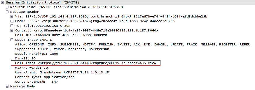
GDMS Settings
UCM can synchronize its SIP accounts to GDMS cloud management system.
http://www.grandstream.com/products/device-management/gdms
To get started, log into your GDMS account and navigate to the System🡪API Developer page. Click on the Enable API Developer Mode button if it has not been enabled yet.
After clicking on it, the API ID and Secret Key will be displayed. Note down these credentials.
On the UCM, navigate to System Settings🡪GDMS Settings. Check the Enable option if it has not been toggled on. Enter your GDMS account credentials and the API developer credentials.
For the Account field, enter either your account username or email address. Once all the information has been entered, click on the Authenticate button to connect to GDMS.
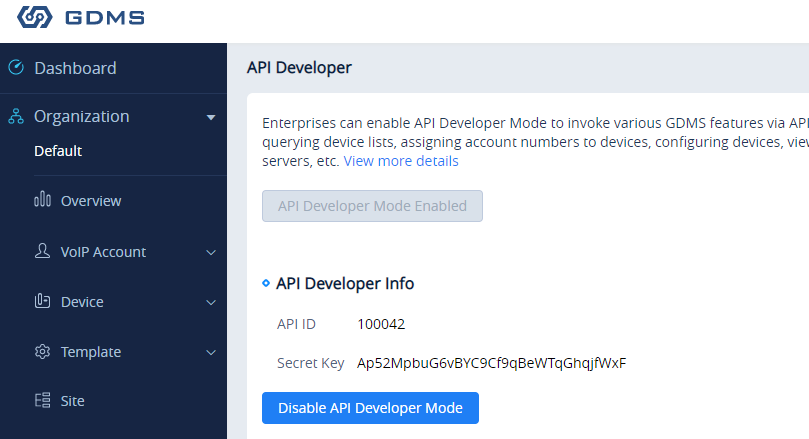
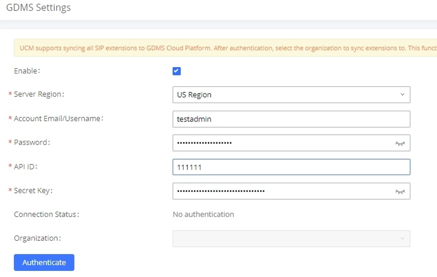
|
Enable |
Toggles GDMS support. If enabled, all SIP extensions on the UCM will be automatically synced to GDMS. |
|
Server Region |
Select your GDMS server region:
|
|
Account Email/Username |
The account email/username for GDMS authentication. |
|
Password |
The password for GDMS authentication. |
|
API ID |
API ID from GDMS account. Refer to [Figure 251: GDMS API Credentials]. |
|
Secret Key |
API secret key from GDMS account. Refer to [Figure 251: GDMS API Credentials]. |
|
Connection Status |
Provides the connection status once authenticated. |
|
Organization |
Name of the organization in GDMS that the UCM SIP server and its extensions will be under. |
|
Authenticate |
Sends the authentication request to GDMS with the entered credentials. |
If the authentication is successful, you will now be able to select an organization on GDMS to synchronize all UCM SIP accounts to. After selecting, saving and applying changes, the UCM will then start the syncing process. Once the initial sync is complete, you will now be able see the UCM and its extensions on GDMS, which will have an orange label with the words “UCM”. Any future creation, deletion, or modification of SIP accounts will automatically be synchronized to GDMS.
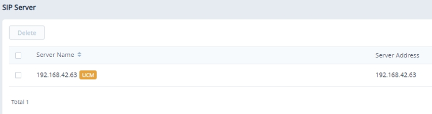
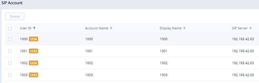
Any future creation, modification, and deletion of the UCM’s SIP extensions will automatically be synchronized to GDMS.
API Configuration
The UCM6510 supports third party billing interface API for external billing software to access CDR and call recordings on the PBX. The API uses HTTPS to request the CDR data and call recording data matching given parameters as configured on the third-party application. More methods are also supported to provide better integration with 3rd party systems.
Before accessing the API, the administrators need to enable the HTTPS API and configure the access/authentication information on the UCM6510 first under Value-added Features🡪API Configuration. The API configuration parameters are available for HTTPS API Settings (New), HTTPS API Settings (Old), CDR Real-time Output Settings & “Upload Prompts User Configuration”.
HTTPS API (New)
Starting from firmware 1.0.20.17, UCM6510 supports new HTTPS API interface to query, edit PBX settings and implement multiple call functions on another server connected to it via API. PBX will actively send system reports and call reports to this other server. Additionally, legacy CDR API, REC API and PMS API are supported.
The table below lists configuration parameters for HTTPS API.
|
HTTPS API Settings (New) | |
|
Enable |
Enable/Disable API. The default setting is disabled. |
|
Username |
Configure the username for API Authentication. |
|
Password |
Configure the password for API Authentication. |
|
Call Control |
If enabled, 3rd party applications will be able to manage inbound calls via API actions. acceptCall will accept incoming calls while refuseCall will reject them. If no actions are done within 10 seconds, calls will automatically be accepted. |
The table below lists new HTTPS API supported methods.
|
getSystemStatus |
addInboundRoute |
listPaginggroup |
|
getSystemGeneralStatus |
getInboundRoute |
addPaginggroup |
|
listAccount |
updateInboundRoute |
getPaginggroup |
|
getSIPAccount |
deleteInboundRoute |
updatePaginggroup |
|
updateSIPAccount |
playPromptByOrg |
deletePaginggroup |
|
listVoIPTrunk |
listBridgedChannels |
MulticastPaging |
|
addSIPTrunk |
listUnBridgedChannels |
MulticastPagingHangup |
|
getSIPTrunk |
Hangup |
listIVR |
|
updateSIPTrunk |
Callbarge |
addIVR |
|
deleteSIPTrunk |
listQueue |
getIVR |
|
listOutboundRoute |
getQueue |
updateIVR |
|
addOutboundRoute |
updateQueue |
deleteIVR |
|
getOutboundRoute |
addQueue |
Cdrapi |
|
updateOutboundRoute |
deleteQueue | |
|
deleteOutboundRoute |
loginLogoffQueueAgent |
Pmsapi |
|
listInboundRoute |
pauseUnpauseQueueAgent |
Queueapi |
|
listDigitalTrunk |
listAnalogTrunk |
getAnalogTrunk |
|
deleteAnalogTrunk |
updateAnalogTrunk |
addAnalogTrunk |
|
addSLATrunk |
updateSLATrunk |
addDigitalTrunk |
|
updateDigitalTrunk |
deletedigitalTrunk |
getDigitalTrunk |
For more details, please refer to online how-to guide available in our website.
HTTPS API (Old)
|
HTTPS API Settings (Old) | |
|
Basic Settings | |
|
Enable |
Enable/Disable API. The default setting is disabled. |
|
TLS Bind Address |
Configure the IP address for TLS server to bind to. “0.0.0.0” means binding to all interfaces. The port number is optional, and the default port number is 8443. The IP address must match the common name (host name) in the certificate so that the TLS socket will not bind to multiple IP addresses. The default setting is 0.0.0.0:8443. |
|
Username |
Configure the username for TLS authentication. |
|
Password |
Configure the password for TLS authentication. |
|
Permitted IP(s) |
Specify a list of IP addresses permitted to use the API. This creates an API-specific access control list. Multiple entries are allowed. For example, “192.168.40.3/255.255.255.255” denies access from all IP addresses except 192.168.40.3. By default, this is blank, which indicates that no IP addresses are allowed to use this API. |
|
Other Settings | |
|
TLS Private Key |
Upload TLS private key. The size of the key file must be under 2MB. This file will be renamed as ‘private.pem’ automatically. |
|
TLS Cert |
Upload TLS cert. The size of the certificate must be under 2MB. This is the certificate file (*.pem format only) for TLS connection. This file will be renamed as “certificate.pem” automatically. It contains private key for the client and signed certificate for the server. |
|
API Module | |
|
CDR API |
Enable/disable CDR API module. |
|
REC API |
Enable/disable REC API module. |
|
PMS API |
Enable/disable PMS API module. |
For more details on CDR API (Access to Call Detail Records), REC API (Access to Call Recording Files) and PMS API, please refer the document in the link here:
- https://documentation.grandstream.com/knowledge-base/cdr-rec-api/
- https://documentation.grandstream.com/knowledge-base/cdr-rec-api/
- PMS API
CDR Real-time Output Settings
CDR Real-time output feature allows to automatically send CDR records once available (after the call is terminated) to a specified server address.
|
CDR Real-time Output Settings | |
|
Enable |
Enables real-time CDR output module. This module connects to selected IP addresses and ports and posts CDR strings as soon as it is available. |
|
Server Address |
CDR server IP address |
|
Port |
CDR server IP port |
|
Choose either TCP protocol or HTTP/HTTPS protocol | |
|
Format |
Choose either XML or JSON for CDR format |
|
Username |
Enter the Username for authentication. |
|
Password |
Enter the Password for authentication. |
For more details, refer to online how-to guide available at:
https://documentation.grandstream.com/knowledge-base/cdr-real-time-output-feature/
CTI Server
UCM supports CTI server capabilities which are designed to be a part of the CTI solution suite provided by Grandstream, which involves the GXP17XX series, GXP21XX series and the GS Affinity application.
By default, the UCM listens to port 8888 for connection requests from the GS Affinity application. This will allow the UCM to interact with, modify, and execute requests by the application such as setting call forwarding and DND.
Users can change the listening port under the menu page, Web GUI🡪Value-added Features🡪CTI Server as shown on below screenshot:
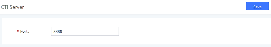
More information about GS affinity and CTI Support on Grandstream products series please refer to the following link: https://documentation.grandstream.com/knowledge-base/gs-affinity-user-guide/
Asterisk Manager Interface (Restricted Access)
Starting from firmware 1.0.1.10, the UCM6510 supports Asterisk Manager Interface (AMI) with restricted access. AMI allows a client program to connect to an Asterisk instance commands or read events over a TCP/IP stream. It is particularly useful when the system admin tries to track the state of a telephony client inside Asterisk.
User could configure AMI parameters on UCM6510 Web GUI🡪Value-added Features🡪AMI. For details on how to use AMI on UCM6510, please refer to the following AMI guide:
https://documentation.grandstream.com/knowledge-base/ami-asterisk-management-interface/
CRM Integration
Customer relationship management (CRM) is a term that refers to practices, strategies and technologies that companies use to manage and analyze customer interactions and data throughout the customer lifecycle, with the goal of improving business relationships with customers.
The UCM6510 supports the following CRM API: SugarCRM, VtigerCRM, ZohoCRM (legacy v1 API), ZohoCRM (v2 API), Salesforce CRM and ACT! CRM. This support allows users to quickly create and modify contacts, leads, and accounts in the CRM from calls made through the UCM.
SugarCRM
Configuration page of the SugarCRM can be accessed via admin login, on the UCM Web GUI🡪Value-added Features🡪CRM.
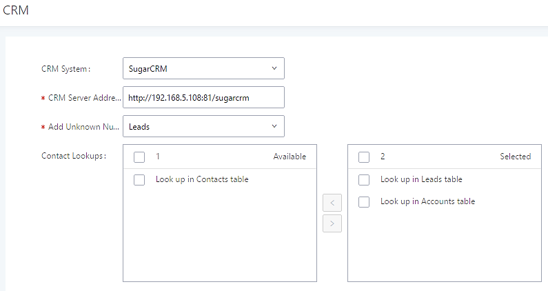
- Select “SugarCRM” from the CRM System Dropdown in order to use SugarCRM.
|
CRM System | Select a CRM system from the dropdown menu, four CRM systems are available: SugarCRM, VtigerCRM, ZohoCRM (legacy v1 API), ZohoCRM (v2 API), Salesforce or ACT! CRM. |
|
CRM Server Address |
Enter the IP address/URL of the CRM server. |
|
Add Unknown Number |
Add the new number to this module if it cannot be found in the selected module. |
|
Contact Lookups |
Select from the “Available” list of lookups and press |
Once settings on admin access are configured:
- Click on
 and
and  .
. - Logout from admin access.
- Login to the UCM as user and navigate under “User Portal🡪Value-added Feature🡪CRM User Settings”.
Click on “Enable CRM” and enter the username/password associated with the CRM account then click on ![]() and
and ![]() . The status will change from “Logged Out” to “Logged In”. User can start then using SugarCRM features.
. The status will change from “Logged Out” to “Logged In”. User can start then using SugarCRM features.
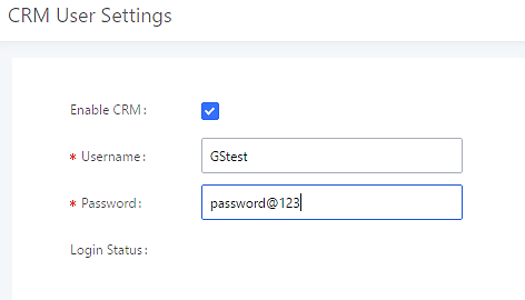
VtigerCRM
Configuration page of the VtigerCRM can be accessed via admin login, on the UCM Web GUI🡪Value-added Features🡪CRM.
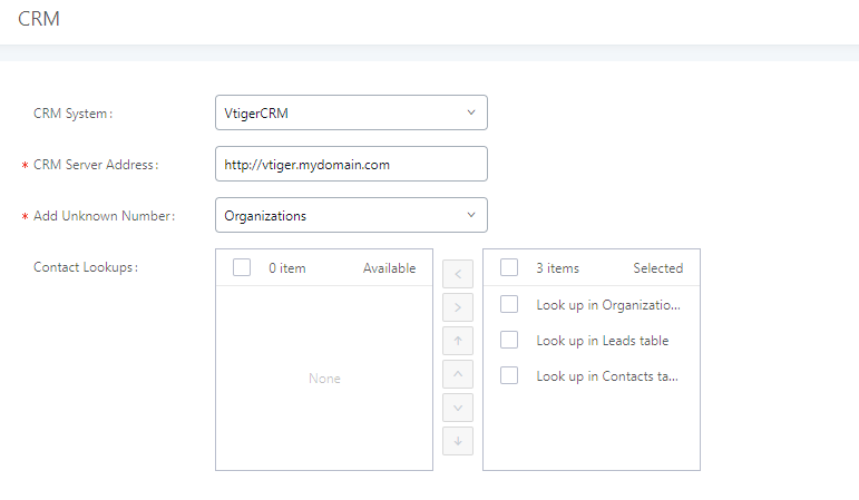
- Select “VtigerCRM” from the CRM System Dropdown in order to use VtigerCRM.
|
CRM System | Select a CRM system from the dropdown menu, four CRM systems are available: SugarCRM, VtigerCRM, ZohoCRM (legacy v1 API), ZohoCRM (v2 API), Salesforce or ACT! CRM. |
|
CRM Server Address |
Enter the IP address/URL of the CRM server. |
|
Add Unknown Number |
Add the new number to this module if it cannot be found in the selected module. |
|
Contact Lookups |
Select from the “Available” list of lookups and press |
Once settings on admin access are configured:
- Click on and .
- Logout from admin access.
- Login to the UCM as user and navigate under “User Portal🡪Value-added Feature🡪CRM User Settings”.
Click on “Enable CRM” and enter the username/password associated with the CRM account then click on ![]() and
and ![]() . The status will change from “Logged Out” to “Logged In”. User can start then using SugarCRM features.
. The status will change from “Logged Out” to “Logged In”. User can start then using SugarCRM features.

ZohoCRM
Configuration page of the ZohoCRM v1 and ZohoCRM v2 can be both accessed via admin login, on the UCM Web GUI🡪Value-added Features🡪CRM.
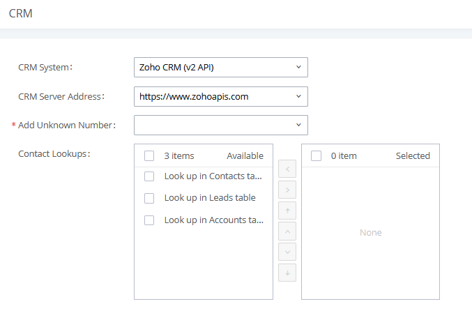
- Select “ZohoCRM (v2 API)” from the CRM System Dropdown in order to use ZohoCRM.
|
CRM System | Select CRM system from the dropdown menu, four CRM systems are available: SugarCRM, VtigerCRM, ZohoCRM (legacy v1 API), ZohoCRM (v2 API), Salesforce or ACT! CRM. |
|
CRM Server Address |
Select Zoho CRM URL from the list. Available options are: |
|
Add Unknown Number |
Add the new number to this module if it cannot be found in the selected module. |
|
Contact Lookups |
Select from the “Available” list of lookups and press |
Once settings on admin access are configured:
- Click on and .
- Logout from admin access.
- Login to the UCM as user and navigate under “User Portal🡪Value-added Feature🡪CRM User Settings”.
Click on “Enable CRM” and enter the username/password associated with the CRM account then click on ![]() and
and ![]() . The status will change from “Logged Out” to “Logged In”. User can start then using ZohoCRM features.
. The status will change from “Logged Out” to “Logged In”. User can start then using ZohoCRM features.
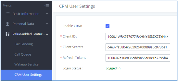
Salesforce CRM
Configuration page of the Salesforce CRM can be accessed via admin login, on the UCM Web GUI🡪Value–added Features🡪CRM”.
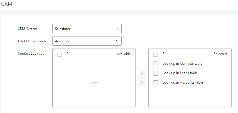
- Select “Salesforce” from the CRM System Dropdown in order to use Salesforce CRM.
|
CRM System | Select a CRM system from the dropdown menu, four CRM systems are available: SugarCRM, VtigerCRM, ZohoCRM (legacy v1 API), ZohoCRM (v2 API), Salesforce or ACT! CRM. |
|
Add Unknown Number |
Add the new number to this module if it cannot be found in the selected module. |
|
Contact Lookups |
Select from the “Available” list of lookups and press |
Once settings on admin access are configured:
- Click on and .
- Logout from admin access.
- Login to the UCM as user and navigate under “User Portal🡪Value-added Feature🡪CRM User Settings”.
Click on “Enable CRM” and enter the username, password and Security Token associated with the CRM account then click on ![]() and
and ![]() . The status will change from “Logged Out” to “Logged In”. User can start then using Salesforce CRM features.
. The status will change from “Logged Out” to “Logged In”. User can start then using Salesforce CRM features.
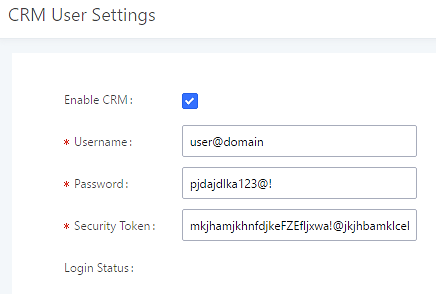
ACT! CRM
Configuration page of the ACT! CRM can be accessed via admin login, on the UCM Web GUI🡪Value–added Features🡪CRM”.
The configuration steps of the ACT! CRM are as follows:
- Navigate to Value-Added Features 🡪 CRM and select the “ACT! CRM” option.
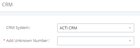
- Log into the UCM as a regular user and navigate to Value-Added Features 🡪 CRM User Settings and check “Enable CRM” option and enter the username and password, which will be the ACT! CRM account’s API Key and Developer Key respectively. To obtain these, please refer to the ACT! CRM API developer’s guide here: https://www.act.com/
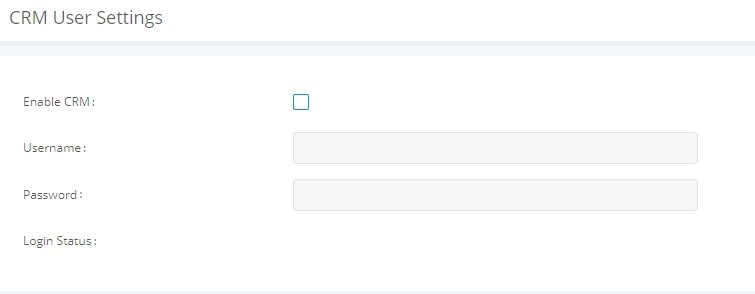
PMS Integration
UCM6510 supports Hotel Property Management System PMS, including check-in/check-out services, wakeup calls, room status, Do Not Disturb which provide an ease of management for hotel applications. This feature can be found on Web GUI🡪Value-added Features🡪PMS.
The PMS module built-in the UCM supports the following features based on each solution:
|
Feature |
Mitel |
HMobile |
HSC |
PMS API |
|
Check-In |
✓ |
✓ |
✗ |
✓ |
|
Check-out |
✓ |
✓ |
✗ |
✓ |
|
Wake-up Call |
✓ |
✓ |
✗ |
✓ |
|
Name Change |
✓ |
✗ |
✓ |
✗ |
|
Update |
✗ |
✓ |
✗ |
✓ |
|
Set Credit |
✓ |
✗ |
✗ |
✗ |
|
Set Station Restriction |
✓ |
✗ |
✓ |
✗ |
|
Room Status |
✗ |
✓ |
✗ |
✗ |
|
Room Move |
✗ |
✓ |
✗ |
✓ |
|
Do Not Disturb |
✗ |
✓ |
✓ |
✗ |
|
Mini Bar |
✗ |
✓ |
✗ |
✗ |
|
MSG |
✗ |
✓ |
✗ |
✗ |
|
MWI |
✗ |
✗ |
✓ |
✗ |
|
Unconditional Call Forward |
✗ |
✗ |
✓ |
✗ |
HMobile PMS Connector
In this mode, the system can be divided into three parts:
- PMS (Property Management System)
- PMSI (Property Management System Interface)
- PBX
Grandstream UCM6XXX series have integrated HMobile Connect PMSI which supports a large variety of PMS software providing following hospitality features: Check-in, Check-out, set Room Status, Wake-up call and more.
The following figure illustrates the communication flow between the PBX (Grandstream UCM6xxx Series) and PMS software, which is done through a middleware system (HMobile Connect) acting as interface between both parties.
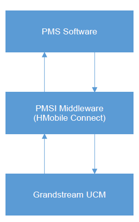
HSC PMS
In this mode, the system can be divided into two parts:
- PMS (Property Management System)
- PBX
Grandstream UCM6XXX series have integrated HSC PMS providing following features:
- Changing Display Name
- Set Station Restriction
- Call forwarding
- DND
- Name Change
- MWI
The following figure illustrates the communication flow between the PBX (Grandstream UCM6xxx Series) and PMS software (HSC), which is done through a middleware system acting as interface between both parties.

Mitel PMS
In this mode, the system can be divided into two parts:
- PMS (Property Management System)
- PBX
Grandstream UCM6XXX series have integrated Mitel PMS providing following hospitality features: Check-in, Check-out, set Room Status, Wake-up call and more.
The following figure illustrates the communication flow between the PBX (Grandstream UCM6xxx Series) and PMS software (Mitel). The communication between both parties is direct with no middleware.
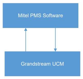
PMS API
The PMS API allows users to use their own middleware to work with PMS systems instead of currently supported integrations.
Additionally, this API allows access to read and modify certain UCM parameters that current supported PMS integrations cannot. To use this, users must first enable and configure the HTTPS API settings.
On the “Old” HTTPS API settings, permitted IP addresses must be configured. Otherwise, the API will be inaccessible. Make sure to check “Enable PMS API”.
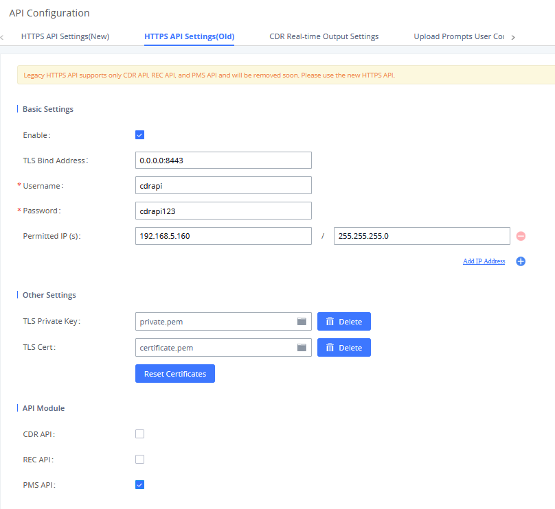
On the “New” HTTPS API, users only need to enable the HTTPS API, which has PMS API functionality built in.
For more details, regarding Old/New HTTPS API, please refer to [API CONFIGURATION].
For more details, please refer to online PMS API Guide.
Connecting to PMS
On the UCM WebGUI🡪Value-added Features🡪PMS🡪Basic Settings” set the connection information for the PMS platform.
| Field | Description |
|---|---|
|
PMS Module |
Users can select the desired PMS module from the drop-down list.
|
|
Wake Up Prompt |
Prompt used when answering the wakeup calls it can be customized from “PBX Settings🡪Voice Prompt🡪Custom Prompt. |
|
PMS URL |
Enter the PMS system URL. If using “Hmobile” PMS Module only. If |
|
UCM Port |
Enter the Port used by the PMS system. Default is 8081. |
|
Username |
Enter the Username to connect to the PMS system. If using “Hmobile” or “HSC” PMS Module only. |
|
Password |
Enter the password to connect to the PMS system. If using “Hmobile” or “HSC” PMS Module only. |
|
Site |
Enter the site to connect to the PMS system. If using “Hmobile” PMS Module only. |
|
If enabled, this option allows backing up voicemail recordings to external storage after check-out. Voicemail can be backed up to SD card, USB disk, NAS, or an SFTP server | |
|
Configure the email address to send the backup to. |
In order to use some PMS features please activate the feature code associated under “Call Features🡪Feature Codes”
- Update PMS Room Status
- PMS Wake Up Service
PMS Features
Room Status
User can create Rooms by clicking on ![]() , the following Figure will be displayed then.
, the following Figure will be displayed then.
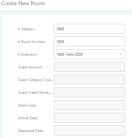
Click “Save” to create the new room, the fields above can be configured from the PMS platform, once set the following screen will be shown:
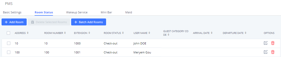
User can create a batch of rooms as well by clicking on ![]() . The following window will pop up:
. The following window will pop up:
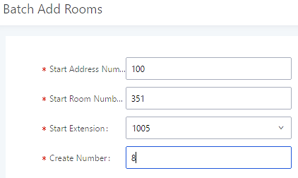
Wake Up Service
To create a New Wake up service, user can click on ![]() . The following window will pop up:
. The following window will pop up:
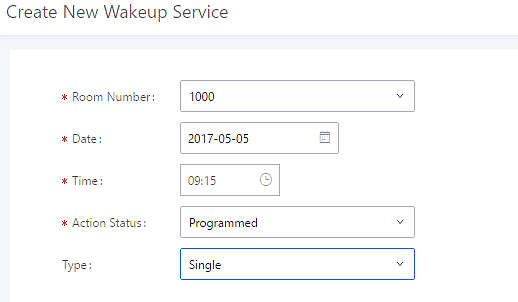
| Field | Description |
|---|---|
|
Select the room to create the wakeup service for. | |
|
Time |
Set the time of the wakeup call |
|
Status of the call:
Note: Editing an already executed wakeup service will automatically change the service’s status to “Programmed”. | |
|
Type |
|
Once the call is made on the time specified, the following figure show the status of the wakeup call.

This call has been executed and answered, that why we can see the “Answered” status.
Mini Bar
In order to create a new mini bar, click on ![]() under UCM webGUI🡪Value-added Features🡪PMS🡪Mini Bar, the following window will pop up:
under UCM webGUI🡪Value-added Features🡪PMS🡪Mini Bar, the following window will pop up:
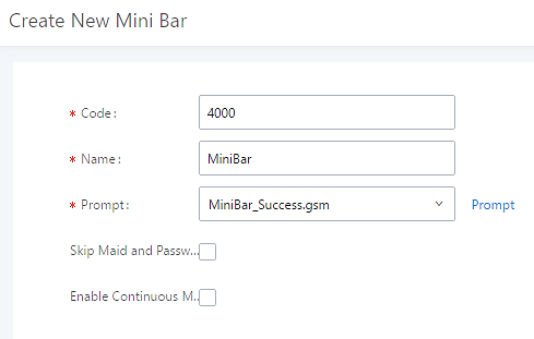
|
Code |
Enter a non-existing extension number to be dialed when using the mini bar feature. |
|
Name |
Enter a name for the mini bar. |
|
Prompt |
Select the Prompt to play once connected to the mini bar. |
|
Skip Maid and Password Authentication |
If enabled, the default maid code will be 0000, no authentication is required. (Enter 0000 followed by # to access the consumer goods) |
|
Enable Continuous Multi Goods Billing |
If enabled, please separate the goods’ codes by*. |
In order to create a new maid, click on ![]() under UCM webGUI 🡪 Value-added Features 🡪 PMS 🡪 Mini Bar, the following window will popup.
under UCM webGUI 🡪 Value-added Features 🡪 PMS 🡪 Mini Bar, the following window will popup.
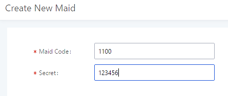
|
Maid Code |
Enter the Code to use when the maid wants to use the Mini Bar. |
|
Secret |
Enter the password associated with the maid. |
In order to create a new consumer goods, click on ![]() under UCM webGUI🡪 Value-added Features 🡪 PMS 🡪 Mini Bar, the following window will popup.
under UCM webGUI🡪 Value-added Features 🡪 PMS 🡪 Mini Bar, the following window will popup.
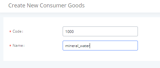
|
Code |
Enter the Goods Code. |
|
Name |
Enter the Name of the Goods |
The Minibar page displays as:
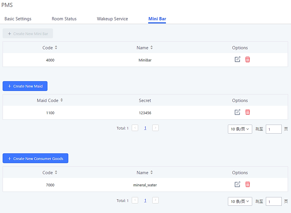
Wakeup Service
The Wakeup service can be used to schedule a reminder/wakeup calls to extensions.
There are three ways to set up Wakeup Service:
- Using admin portal
- Using user portal
- Using feature code
Wakeup Service using Admin Login
- Log in to the UCM as admin.
- Wakeup service can be found under Web GUI🡪Value-added Features🡪Wakeup Service, click on
 to create a new wakeup service. The following window will popup.
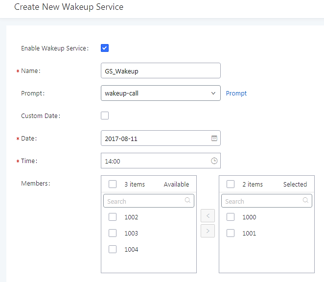
|
Enable Wakeup Service |
Enable Wakeup service. |
|
Name |
Enter a name (up to 64 characters) to identify the wakeup service. |
|
Prompt |
Select the prompt to play upon answering the wakeup call.. |
|
Custom Date |
If disabled, users can select a specific date and time. If enabled users can select multiple days of the week to perform the wakeup. |
|
Date |
Select the date or dates when to performs the wakeup call. |
|
Time |
Select the time when to send the wakeup call. |
|
Members |
Select the extensions to send the wakeup call to. |
- Click and to apply the changes.
A wakeup service entry is created. The UCM will send a wakeup call to every extension in the member list at the scheduled date and time.
The wakeup service has the following limitation on how many members can be added depending on UCM model.
|
UCM Model |
Max members in a Wakeup Service |
|
UCM6202 |
50 |
|
UCM6204 |
50 |
|
UCM6208 |
100 |
|
UCM6510 |
100 |
Wakeup Service from User Portal
- Log into the UCM user portal.
- Wakeup service can be found under “Value-added Features🡪Wakeup Service”, click on to create a new wakeup service.
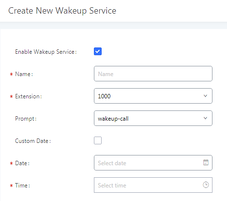
- Configure the Name, Prompt, Date and Time for the wakeup call
- Click and to apply the changes. A wakeup service entry is created. The UCM will send a wakeup call at the scheduled date and time.
Wakeup Service using Feature Code
- Log into the UCM admin portal.
- Enable “Wakeup Service” from the WebGUI under the Call Features🡪Feature Codes🡪Feature Codes page.
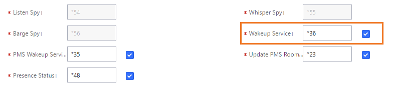
- Click and to apply the changes.
- Dial the Wakeup Service feature code (*36 by default) to access to the UCM wakeup service.
- Users have the choice to set a wakeup service for tomorrow or specify another day when adding a wakeup service.
- A wakeup service entry is created. The UCM will send a wakeup call at the scheduled date and time.
Announcements Center
Starting from firmware 1.0.2.7, UCM supports Announcement Center functionality. By dialing a code associated with a custom prompt along with a configured Announcement Group number, users can quickly send audio prompts to specified groups of extensions.

Announcements Center Setting
|
Name |
Configure a name for the Announcements Center. |
|
Code |
Enter a code number to associate the audio prompt with. This code will be used in combination with the Group Number. Example: If the code is 55, and the group number is 666, dialing 66555 will send the prompt associated with code 55 to all the members of Group 666. Note: The combined number must not conflict with any existing extension on the UCM. |
|
Custom Prompt |
Configures the custom prompt to play to announcement group members. Prompts can be directly uploaded from this page. Note: Prompt filenames cannot exceed 100 characters. |
|
Ring Timeout |
Configure the ring timeout for the group members. The default value is 30 seconds. |
Group Setting
|
Configure a name for the Announcement group Note: Name cannot exceed 64 characters. | |
|
Configure the group number. The group number is used in combination with code. For example, if group number is 666, and code is 55. User dials 55666 will send prompt 55 to all members in group 666. Note: The group number must not conflict with any other numbers, such as extension or conference number and cannot exceed 64 characters. |
Announcements Center feature can be found under Web GUI🡪Value-added Features🡪Announcements Center. The following example demonstrates the usage of this feature.
- Click
 to create new group.
 - Configure a name and number for the group.
- Select the extensions that will be in the group.
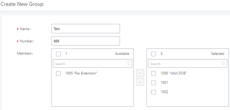
Here, Group Test’s number is 666 and has extensions 1000, 1001, and 1002 as members of the group.
- Click
 to create a new Announcement Center.
 - Configure the Announcement Center name and code to associate with the custom prompt.
- Select the audio prompt that will be associated with the configured code. Users can directly upload audio prompts to use from this page.
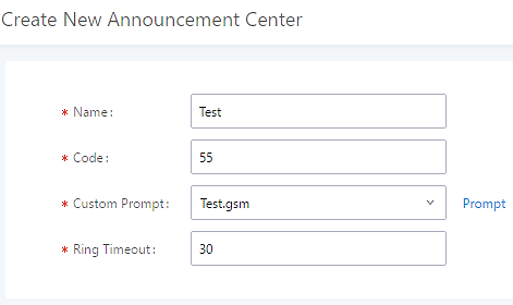
Code and Group number are used together to direct specified message to the target group. All extensions in the group will received the message. For example, in this example, we can send code 55 to group 666.
Sending 55 (code) + 666 (group number) will send an announcement with the associated audio prompt to all the members of Group Test.
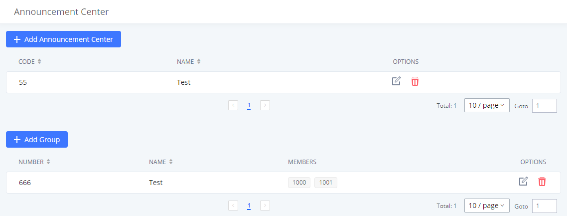
QueueMetrics Integration
The UCM now supports QueueMetrics, a highly scalable monitoring and reporting suite that addresses the needs of thousands of call centers worldwide and offers a broad range of benefits and services.
UCM currently supports the following features with QueueMetrics: Agent login, Agent Logoff, Realtime Monitoring-Pausing, Realtime Monitoring-Barging, Realtime Monitoring-Transferring, Realtime Monitoring-End calls, Generating Performance Report-Quick and Agent today.
API Configuration Parameters
Configuration page of the QueueMetrics can be accessed via admin login, on the UCM Web GUI🡪Value-added Features🡪QueueMetrics.
To Integrate QueueMetrics with the UCM, please follow the steps below:
- Enable the option QueueMetrics Integration.
- Enter the QueueMetrics URL provided.
- Set the Username and the account code to the account name and password provided from QueueMetrics.
- Click on Save and Apply Changes.
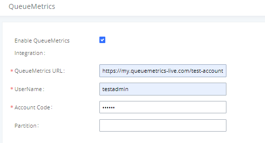
|
QueueMetrics | |
|
Enable QueueMetrics Integration |
Enable/Disable QueueMetrics Integration. |
|
QueueMetrics URL |
Configure the URL for QueueMetrics Integration. |
|
Username |
Configure the username for QueueMetrics authentication. |
|
Account Code |
Configure the password for QueueMetrics authentication. |
|
Partition |
Configure Data storage partition identifier. |
For more details, please refer to online guide:
https://documentation.grandstream.com/knowledge-base/queuemetrics-integration/
Status and Reporting
PBX Status
The UCM Dashboard page under System Status🡪Dashboard provides a real-time overview of the system’s trunks, extensions, queues, conference rooms, interface status, digital channels, and parking lots.
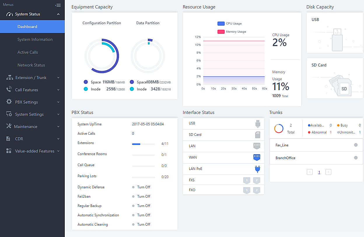
Trunks
Users can see the status of all configured trunks.
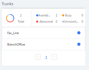
|
Status |
Display trunk status.
Available Busy Unavailable Unknown Error Error Configured: Incorrect signaling configuration between the two devices. For example, both of the devices are configured as CPE or NET.
Unreachable: The hostname cannot be reached. Unmonitored: This requires “Keep-alive” to be enabled for the trunk, not the QUALIFY feature. Reachable: The hostname can be reached.
Registered Unrecognized Trunk |
|
Trunks |
Display trunk name |
|
Type |
Display trunk Type:
|
|
Username |
Display username for this trunk. |
|
Port/Hostname/IP |
Display Port for analog trunk, or Hostname/IP for VoIP (SIP/IAX) trunk. |
Extensions
Extensions Status can be seen from the same configuration page, users can go under Web GUI🡪Extension/Trunk🡪Extensions and following page will be displayed listing the extensions and their status information.
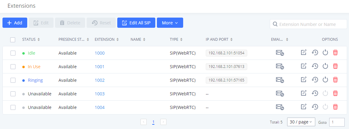
|
Status |
Display extension number (including feature code). The color indicator has the following definitions.
|
|
Presence Status |
Display the presence status of the extension. |
|
Extension |
Display the extension number. |
|
Name |
First name and last name of the extension. |
|
IP and Port |
Display the IP and port number of the registered device. |
|
|
Display Email Notification status for the extension. SIP Account email notification has not been sent.
|
|
Type |
Displays extension type.
|
Interfaces Status
This section displays interface connection status on the UCM6510 for USB, SD Card, LAN, WAN, LAN PoE, Heartbeat, Power 1, Power 2, Digital, FXS and FXO ports.
|
FXO | |
 |
Disconnected |
 |
Connected but not configured |
 |
Connected and idle |
 |
Connected and in use |
|
FXS | |
 |
Connected but not configured |
 |
Connected and idle |
 |
Connected and in use |
|
SD Card | |
 |
SD Card plugged in |
 |
SD Card unplugged |
|
USB | |
 |
USB plugged in |
 |
USB unplugged |
|
LAN PoE | |
 |
PoE is used |
 |
PoE is not used |
|
Power ½ | |
 |
Power supply is working |
 |
Power supply is abnormal |
 |
No power supply |
|
LAN/WAN/Heartbeat | |
 |
Connected |
 |
Not connected |
|
Digital Port T1/E1/J1 | |
 |
Connected and working |
 |
RED alarm: there is physical wiring problem, loss of connectivity, or a framing/line-coding mismatch with the remote switch. |
 |
YELLOW alarm: connected but the link is working only one-way. This means that the remote switch is not able to maintain sync with you or is not receiving your transmission. The following example scenarios could trigger YELLOW alarm:
|
 |
BLUE alarm: the port goes into BLUE alarm when it receives all unframed 1s on all timeslots from the remote switch. This is a special signal to indicate that the remote switch is having problem with its upstream connection. |
 |
Cannot start up |
System Status
The UCM6510 system status can be accessed via Web GUI🡪System Status, which displays the following system information.
General
Under Web GUI🡪System Status🡪System Information🡪General, users could check the hardware and software information for the UCM6510. Please see details in the following table.
|
System Status 🡪System Information🡪General | |
|
Model |
Product model. |
|
Part Number |
Product part number. |
|
System Time |
Current system time. The current system time is also available on the upper right of each web page. |
|
Up Time |
System up time since the last reboot. |
|
Idle Time |
System idle time since the last reboot. |
|
Boot |
Boot version. |
|
Core |
Core version. |
|
Base |
Base version. |
|
Program |
Program version. This is the main software release version. |
|
Recovery |
Recovery version. |
Network
Under Web GUI🡪System Status🡪System Information🡪Network, users could check the network information for the UCM6510. Please see details in the following table.
|
System Status🡪System Information🡪Network | |
|
MAC Address |
Global unique ID of device, in HEX format. The MAC address can be found on the label coming with original box and on the label located on the bottom of the device. |
|
IP Address |
IP address. |
|
Gateway |
Default gateway address. |
|
Subnet Mask |
Subnet mask address. |
|
DNS Server |
DNS Server address. |
|
Network Port Speed. | |
|
Shows the Duplex Mode (Full/Half Duplex). |
Storage Usage
Users could access the storage usage information from Web GUI🡪System Status🡪Dashboard 🡪Space Usage. It shows the available and used space for Space Usage and Inode Usage.
Space Usage includes:
- Configuration partition
- This partition contains PBX system configuration files and service configuration files.
- Data partition
- Voicemail, recording files, IVR file, Music on Hold files and etc.
- USB disk
- USB disk will display if connected.
- SD Card
- SD Card will display if connected.
Inode Usage includes:
- Configuration partition
- Data partition
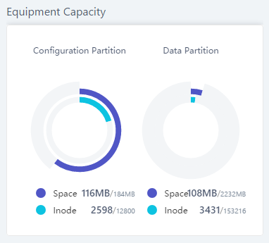
Resource Usage
When configuring and managing the UCM6510, users could access resource usage information to estimate the current usage and allocate the resources accordingly. Under Web GUI🡪System Status🡪Dashboard 🡪Resource Usage, the current CPU usage and Memory usage are shown in the pie chart.
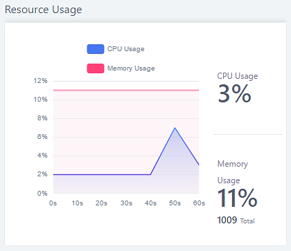
System Events
The UCM6510 can monitor important system events, log the alerts and send email notifications to specified email addresses.
Alert Events List
The system alert events list can be found under Web GUI🡪Maintenance🡪System Events. The following events are currently supported on the UCM. Alerts for these events will be generated if abnormalities occur:
| Action index | Alert Events |
|---|---|
|
1 |
Disk Usage |
|
2 |
Modify Super Admin Password |
|
3 |
Memory Usage |
|
4 |
System Reboot |
|
5 |
System Update |
|
6 |
System Crash |
|
7 |
Register SIP failed |
|
8 |
Register SIP trunk failed |
|
9 |
Restore Config |
|
10 |
User login success |
|
11 |
User login failed |
|
12 |
SIP Internal Call Failure |
|
13 |
SIP Outgoing Call through Trunk Failure |
|
14 |
Fail2ban Blocking |
|
15 |
SIP Lost Registration |
|
16 |
SIP Peer Trunk Status |
|
17 |
User Login Banned |
|
18 |
External Disk Usage |
|
19 |
HA failure warning |
|
20 |
Emergency Calls |
|
21 |
The CDR database is corrupted |
|
22 |
NAS |
|
23 | |
|
24 |
Click on ![]() to configure the parameters for each event.
to configure the parameters for each event.
- Disk Usage
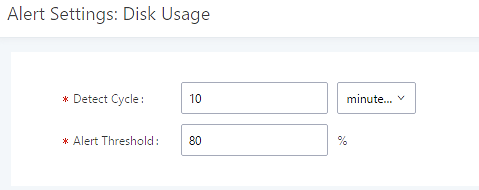
- Detect Cycle: The UCM6510 will perform the internal disk usage detection based on this cycle. Users can enter the number and then select second(s)/minute(s)/hour(s)/day(s) to configure the cycle.
- Alert Threshold: If the detected value exceeds the threshold (in percentage), the UCM6510 system will send the alert.
- External Disk Usage
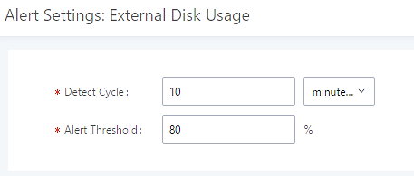
- Detect Cycle: The UCM6510 will perform the External disk usage detection based on this cycle. Users can enter the number and then select second(s)/minute(s)/hour(s)/day(s) to configure the cycle.
- Alert Threshold: If the detected value exceeds the threshold (in percentage), the UCM6510 system will send the alert.
- Memory Usage
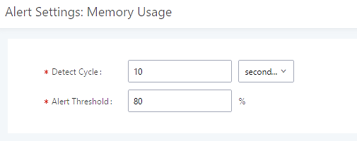
- Detect Cycle: The UCM6510 will perform the memory usage detection based on this cycle. Users can enter the number and then select second(s)/minute(s)/hour(s)/day(s) to configure the cycle.
- Alert Threshold: If the detected value exceeds the threshold (in percentage), the UCM6510 system will send the alert.
- System Crash
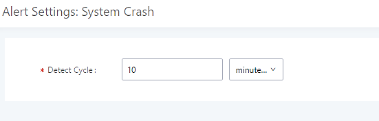
- Detect Cycle: The UCM6510 will detect the event at each cycle based on the specified time. Users can enter the number and then select second(s)/minute(s)/hour(s)/day(s) to configure the cycle.
Click on the switch ![]()
![]() to turn on/off the alert and Email notification for the event. Users could also select the checkbox for each event and then click on button “Alert On”, “Alert Off”, “Email Notification On”, “Email Notification Off” to control the alert and Email notification configuration.
to turn on/off the alert and Email notification for the event. Users could also select the checkbox for each event and then click on button “Alert On”, “Alert Off”, “Email Notification On”, “Email Notification Off” to control the alert and Email notification configuration.
Alert Log
Under Web GUI🡪Status🡪System Events🡪Alert Log, system messages are listed when the alert is triggered for the configured system events. The following picture shows disk usage alert log. We can tell the detect cycle for the disk usage is 10 minutes and the disk usage is restored to normal after the administrator cleans up the disk storage below the threshold.
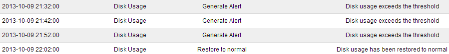
The following screenshot shows system crash alert logs.
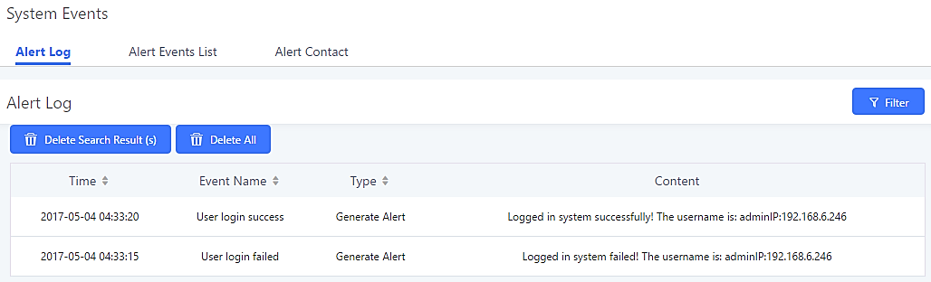
User could also filter alert logs by selecting a certain event category, type of alert log, and/or specifying a certain time period. The matching results will be displayed after clicking on ![]() . Alert logs are playlistified into two types by the system:
. Alert logs are playlistified into two types by the system:
- Generate Alert: Generated when alert events happen, for example, alert logs for disk usage exceeding the alert threshold.
- Restore to Normal: Generated when alert events being cleared, for example, logs for disk usage dropping back below the alert threshold.
User could filter out alert logs of “Generate Alert” or “Restore to Normal” by specifying the type according to need. The following figure shows an example of filtering out alert logs of type of “Restore to Normal”.
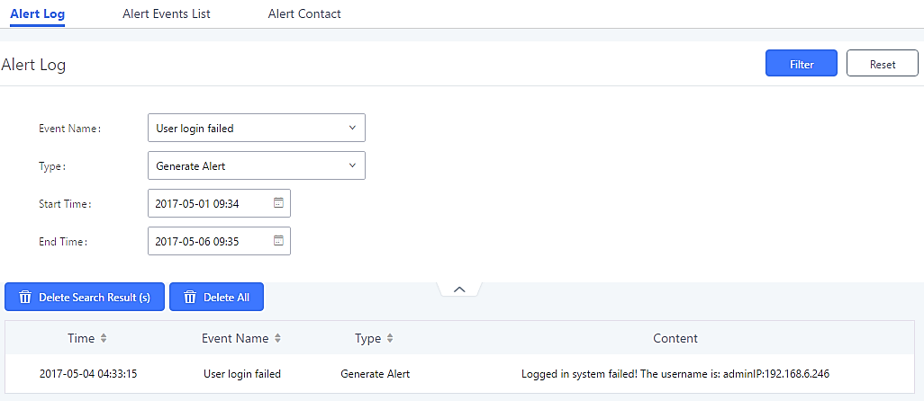
Alert Contact
This feature allows the administrator to be notified when one of the Alert events mentioned above happens. Users could add administrator’s Email address under Web GUI🡪Maintenance🡪System Events🡪Alert Contact to send the alert notification to an email (Up to 10 Email addresses can be added) or also specify an HTTP server where to send this alert.
|
Super Admin Email |
Configure the email addresses to send alert notifications to. Up to 10 email addresses can be added. |
|
Admin Email |
Configure the email addresses to send alert notifications to. Up to 10 email addresses can be added. |
|
Email Template |
Please refer to section Password |
|
Protocol |
Protocol used to communicate with the server. HTTP or HTTPS. Default one is HTTP. |
|
HTTP Server |
The IP address or FQDN of the HTTP server. |
|
HTTP Server Port |
HTTP/HTTPS port |
|
Warning Template |
Customize the template used for system warnings. Default one: {“action”:”${ACTION}”,”mac”:”${MAC}”,”content”:”${WARNING_MSG}”} |
|
Notification Template |
Customize the notification template to receive relevant alert information. By default: {“action”:”${ACTION}”,”cpu”:”${CPU_USED}”,”memery”:”${MEM_USED}”,”disk”:”${DISK_USED}”,”external_disk”:”${EXTERNAL_DISK_USED}”} Note: The notification message with “action:0” will be sent periodically if Notification Interval is set. |
|
Notification Interval |
Modifies the frequency at which notifications are sent in seconds. No notifications will be sent if the value is “0”. Default value: 20 |
|
Template Variables |
${MAC} : MAC Address ${WARNING_MSG} : Warning message ${TIME} : Current System Time ${CPU_USED} : CPU Usage ${MEM_USED} : Memory Usage ${ACTION} : Message Type. Refer to [Table 147: Alert Events] ${DISK_USED} : Disk Usage ${EXTERNAL_DISK_USED} : Disk Usage |
CDR
CDR (Call Detail Record) is a data record generated by the PBX that contains attributes specific to a single instance of phone call handled by the PBX. It has several data fields to provide detailed description for the call, such as phone number of the calling party, phone number of the receiving party, start time, call duration, and etc.
On the UCM6510, the CDR can be accessed under Web GUI🡪CDR🡪CDR. Users could filter the call report by specifying the date range and criteria, depending on how the users would like to include the logs to the report. Click on “Search” button to display the generated report.
Important Note: Starting from firmware 1.0.15.16, the UCM has CDR separation and it will display only CDR for the current month. To view data of the previous months, users will need to apply a filter with a specified date range.
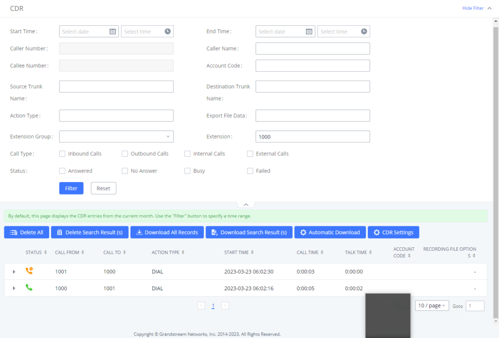
Call Type |
External calls: External calls are calls sent from one trunk to another trunk and are not sent to any internal extension. |
Status | Filter with the call status, the available statuses are the following:
|
Source Trunk Name | Filter out calls originating from the selected trunks. |
Destination Trunk Name | Filter out calls that were sent to the selected trunks. |
Action Type | Filter calls based on the Action Type. The following actions are available:
|
Extension Group | Filters calls made to the selected Extension Group. |
Extension | Filters a specific Extension or a range of Extensions via patterns. Supported characters are: . … Matches zero or more of any character. Should only be attached to the end of a pattern. Examples: |
Account Code | Filter calls with the specified Account Code. If Outbound Routes->PIN Groups->Record in CDR is enabled, Account Code information will be displayed in the CDR if applicable. |
Start Time | Specify the earliest date and time of CDR to filter. |
End Time | Specify the latest date and time of CDR to filter. |
Caller Number | Enter the caller number of the CDR to filter. Patterns can be used to filter calls made from groups of similar numbers. |
Caller Name | Enter the caller name of the CDR to filter. |
Callee Number | Enter the callee number of the CDR to filter. |
The call report will display as the following figure shows.
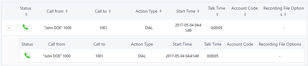
The CDR report has the following data fields:
- Start Time
Format: 2016-09-03 00:06:16
- Call Type
Example:
IVR
DIAL
WAKEUP
- Call From
Example format:
“John Doe” 2000
- Call To
Example format:
2002
- Call Time
Format: 0:00:02
- Talk Time
Format: 0:00:00
- Account Code
Example format:
Grandstream/Test
- Status
Answered, Busy, No answer or Failed.
Users could perform the following operations on the call report.
- Sort by “Start Time”
Click on the header of the column to sort the report by “Start Time”. Clicking on “Start Time” again will reverse the order.
- Download Search Results
Click on “Download Search Result(s)” to export the filtered CDR to a .CSV file.
- Download All Records
Click on “Download All Records” to export all the records to a .CSV file. - Delete All
Click on button to remove all the call report information.
 - Delete Search Result
On the bottom of the page, click on button to reomve the filtered CDR entries
- Play/Download/Delete Recording File (per entry)
If the entry has audio recording file for the call, the three icons on the rightest column will be activated for users to select. In the following picture, the second entry has audio recording file for the call.- Click on to play the recording file. Click on to download the recording file in .wav format.
- Click on to delete the recording file (the call record entry will not be deleted).
- Click on
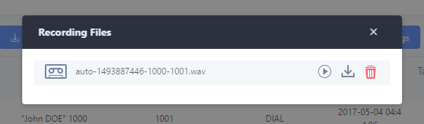
- Automatic Download CDR Records
Users can configure the UCM to periodically send the CDR to a configured email address. Click on “Automatic Download” and configure the parameters in the dialog below.
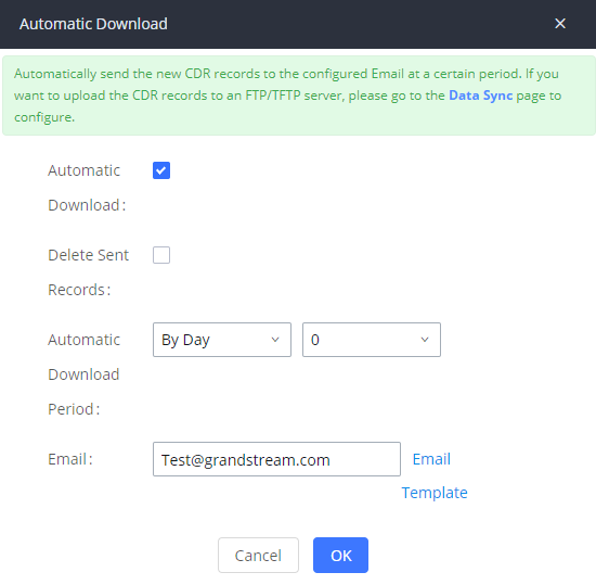
|
Enable the Automatic Download feature. | |
|
Delete Sent Records |
Whether to delete the sent records or not. |
|
Automatic Download Period |
Configure the Automatic Download Period |
|
|
Email address blacklist/whitelist for non-local contacts. Separate multiple addresses with semicolon (;) (i.e.”xxx;yyy”). |
CDR Improvement
Starting from UCM6510 firmware 1.0.10.x, transferred call will no longer be displayed as a separate call entry in CDR. It will display within call record in the same entry. CDR new features can be found under Web GUI🡪CDR🡪CDR. Users can click on the ![]() icon to expand call details and view various legs of the call.
icon to expand call details and view various legs of the call.

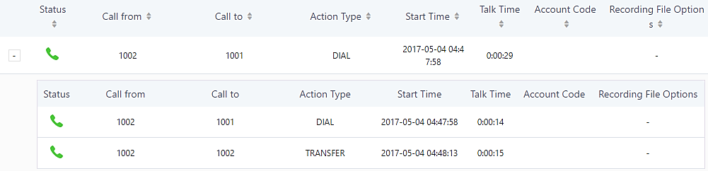
Downloaded CDR File
The downloaded CDR (.csv file) has different format from the Web GUI CDR. Here are some descriptions.
- Caller number, Callee number
“Caller number”: the caller ID.
“Callee number”: the Callee ID.
If the “Source Channel” contains “DAHDI”, this means the call is from FXO/PSTN line.
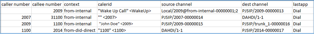
- Context
There are different context values that might show up in the downloaded CDR file. The actual value can vary case by case. Here are some sample values and their descriptions.
from-internal: internal extension makes outbound calls.
ext-did-XXXXX: inbound calls. It starts with “ext-did”, and “XXXXX” content varies case by case, which also relate to the order when the trunk is created.
ext-local: internal calls between local extensions.
- Source Channel, Dest Channel
Sample 1:

DAHDI means it is an analog call, FXO or FXS.
For UCM6510, DAHDI/(1-2) are FXO ports, and DAHDI(3-4) are FXS ports.
Sample 2:

“SIP” means it is a SIP call. There are three possible formats:
(a) PJSIP/NUM-XXXXXX, where NUM is the local SIP extension number. The last XXXXX is a random string and can be ignored.
(c) PJSIP/trunk_X/NUM, where trunk_X is the internal trunk name, and NUM is the number to dial out through the trunk.
(c) PJSIP/trunk_X-XXXXXX, where trunk_X is the internal trunk name and it is an inbound call from this trunk. The last XXXXX is a random string and can be ignored.
There are some other possible values, but these values are almost the application name which are used by the dialplan.
IAX2/NUM-XXXXXXX: it means this is an IAX call.
Local/@from-internal-XXXXX: it is used internally to do some special feature procedure. We can simply ignore it.
Hangup: the call is hung up from the dial plan. This indicates there are some errors, or it has run into abnormal cases.
Playback: play some prompts to you, such as 183 response or run into an IVR.
ReadExten: collect numbers from user. It may occur when you input PIN codes or run into DISA.
CDR Export Customization
Users can select the data they want to see in exported CDR reports by first clicking on the Filter button on the CDR page under CDR🡪CDR and selecting the desired information in the Export File Data field.
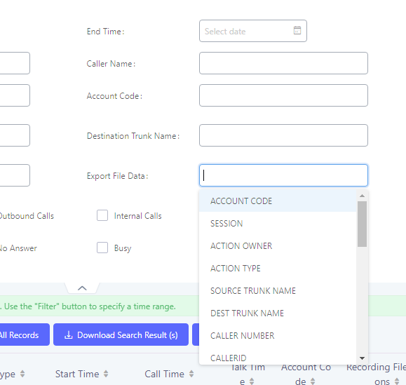
Statistics
CDR Statistics is an additional feature on the UCM6510 which provides users a visual overview of calls across a period of time. Users can filter with different criteria to generate the statistics chart.
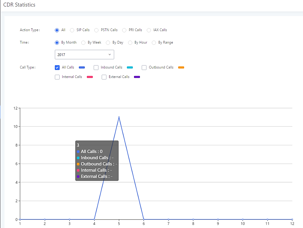
|
Trunk Type |
Select one of the following trunk types.
|
|
Call Type |
Select one or more in the following checkboxes.
|
|
Time Range |
|
Recording Files
The Recording Files page lists all recordings saved via “Auto Record” or “Start/Stop Call Recording” feature code. If external storage (e.g., NAS, SD card, USB disk, etc.) is connected, recordings will be saved there. If no external storage is available, the recordings will be stored in UCM local storage.
- Click on “Delete Selected Recording Files” to delete the recording files.
- Click on “Delete All Recording Files” to delete all recording files.
- Click on “Batch Download Recording Files” in order to download the selected recording files.
- Click on “Download All Recording Files” to download all recordings files.
- Select either “USB Disk” or “Local” or “NAS” to show recording files stored on external or internal storage, depending on selected storage space.
- Select whether to show call recordings, queue recordings or conference recordings.
- Click on to download the recording file in .wav format.
- Click on to delete the recording file.
- To sort the recording file, click on the title “Caller”, “Callee” or “Call Time” for the corresponding column. Click on the title again can switch the sorting mode between ascending order or descending order.
User Portal
Users could log into their web GUI portal using the extension number and user password. When an extension is created in the UCM6510, the corresponding user account for the extension is automatically created. The user portal allows access to a variety of features which include user information, extension configuration and CDR as well as settings and managing value-added features like Fax Sending, Call Queue, Wakeup Service and CRM.
Users also can access their personal data files such as call recordings, fax files, and voicemail prompts.
The login credentials are configured by Super Admin. The following figure shows the User Management🡪Edit User page for extension 1000. Username for an extension account cannot be modified. Please note that User Password and SIP Password are different fields and should not be mistaken for one another.
The following figure is an example of logging in with an extension account.
Upon successfully logging in, the following page will appear.
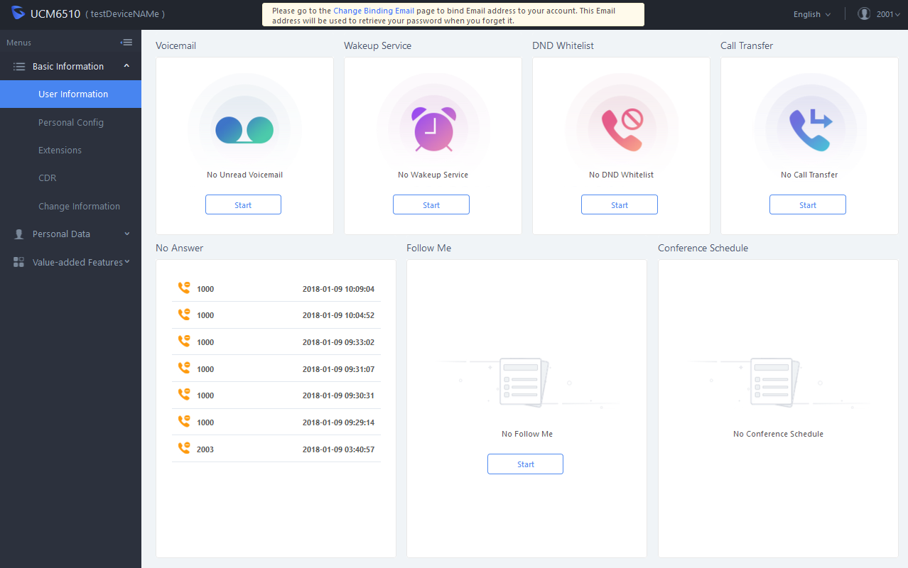
Basic Information
Under this menu, the user can configure and change his/her personal such as first name, last name, user password, email address, and department. Users can set extension features such as presence status and call forwarding and view their CDR.
Personal Data
In this section, users can access and manage their personal files such as voicemail, call recordings, and fax and set up Follow-Me.
Value-added Features
On this section, the user has access to manage and use all rich value-added features which includes:
Fax Sending
For Fax Sending configuration parameters, please refer to the [Fax Sending] section.
Call Queue
If user is a member of call queue, they can check the queue’s activity and for more information, please refer to [Queue Agent] section.
Wakeup Service
This section allows users to create and enable Wakeup service and for more information, please refer to [Wakeup Service from User Portal].
CRM User Settings
This section allows users to enable and configure CRM connection to either SugarCRM or Salesforce.
High Availability
The UCM6510 can interact with the HA100, a module designed to provide high availability failover functionality. This connection offers a breakthrough turnkey solution for converged voice, video, data, fax, security surveillance, and mobility applications out of the box without any extra license fees or recurring costs.
Deployment Methods
In a setup with an HA100 device and two UCM6510, if hardware issues are detected within the primary UCM, services provided by the primary UCM will switch over to the secondary UCM, minimizing the amount of service downtime.
There are two recommended methods for creating an HA setup:
Method 1: Backup and restore a configuration from UCM A
- Upgrade UCM A to at least firmware version 1.0.15.16.
- Create a full backup of UCM A.
- Upgrade UCM B to at least firmware version 1.0.15.16.
- Restore the backup from UCM A to UCM B. UCM B should now have the same configuration and firmware as UCM A.
- Follow the installation instructions from the HA100 Quick Installation Guide to ensure that UCM A, UCM B, and the HA device are properly connected and turned on.
- Access UCM A’s web portal, navigate to System Settings->HA, enable High Available Enable, and reboot the UCM. UCM B should also reboot during this time.
- HA setup is now complete.
Method 2: Allow UCM A to synchronize its configuration with UCM B
- Upgrade UCM A to at least firmware version 1.0.15.16.
- Create a full backup of UCM A in case of syncing issues.
- Upgrade UCM B to at least firmware version 1.0.15.16. While not required, it is recommended that UCM B be factory reset.
- Follow the installation instructions from the HA100 Quick Installation Guide to ensure that UCM A, UCM B, and the HA device are properly connected and turned on with the exception of the Heartbeat connection between UCM A and UCM B.
- Access UCM A’s web portal, navigate to System Settings->HA, enable High Available Enable, and reboot the device. UCM B should also reboot during this time.
- Connect UCM A and UCM B via their Heartbeat ports.
- UCM A should now synchronize its configuration with UCM B
HA setup is now complete.
HA100 Configuration
The High Availability settings are available under the Web UI🡪System Settings🡪HA. The following table describes the HA options:
|
High Available Enable |
Enables/disables the HA functionality. By default, is Disabled. |
|
Hardware Scan |
Select the hardware interface to be scanned, and the system will determine whether the interface is faulty. |
|
Fault Switch |
When the selected hardware interfaces have fault, the backup UCM6510 take over services after master/slave handover. If not checked, UCM only report fault alarm. |
|
Heartbeat Port |
Specifies the heartbeat port. Default setting is: 9527 and valid range is from 0 to 65535. |
|
Heartbeat Timeout Period (s) |
Specifies the heartbeat timeout period. If timeout occurs, slave UCM will take over master’s service. Default setting is: 7(s) and valid range is from 0 to 9. |
|
File Backup Interval(min) |
Specifies the file backup interval period which synchronize the relevant files to standby UCM at any given time (including records, voice mail, voice files, etc.). Default setting is 30(min) and valid range is from 30 to 720. |
Upgrading HA100
As we advise to always keep maintaining and upgrading the firmware on all your Grandstream devices, users could download the latest firmware version for the HA100 from the following link:
https://www.grandstream.com/support/firmware/
After this, please follow below steps in order to upgrade the unit:
- From the web GUI, navigate under the menu System Settings🡪HA🡪HA Deconcentrator Firmware Upgrade.
- Ensure that the active UCM’s RS485 cable is connected to the HA device.
- Press the Reset button on the HA100 unit.
- Upload the downloaded firmware file.
Upgrading UCM6510s Connected to the HA100
The steps to upgrade both UCMs with an HA are the same as upgrading a single UCM.
- Ensure that all connections between the HA and the two UCMs are secure and working properly.
- Assuming that UCM A is the master and that UCM B is the slave, create a full backup of UCM A.
- From UCM A’s web portal, upgrade UCM A to the desired firmware. UCM B will also be upgrading during this time.
- Reboot the device when prompted. UCM B will automatically reboot alongside UCM A.
- Upon booting back up, UCM A and UCM B’s LCD displays should show “Master” and “Slave” respectively.
- Data syncing may occur for 5 or more minutes. If users cannot access the UCM web portal after booting up, please wait until the data sync is complete and try again.
Maintenance
User Management
User management is on Web GUI🡪 Maintenance🡪User Management page. User could create multiple accounts for different administrators to log in the UCM6510 Web GUI. Additionally, the system will automatically create user accounts along with creating new extensions for extension users to login to the Web GUI using their extension number and password. All existing user accounts for Web GUI login will be displayed on User Management page as shown in the following figure.
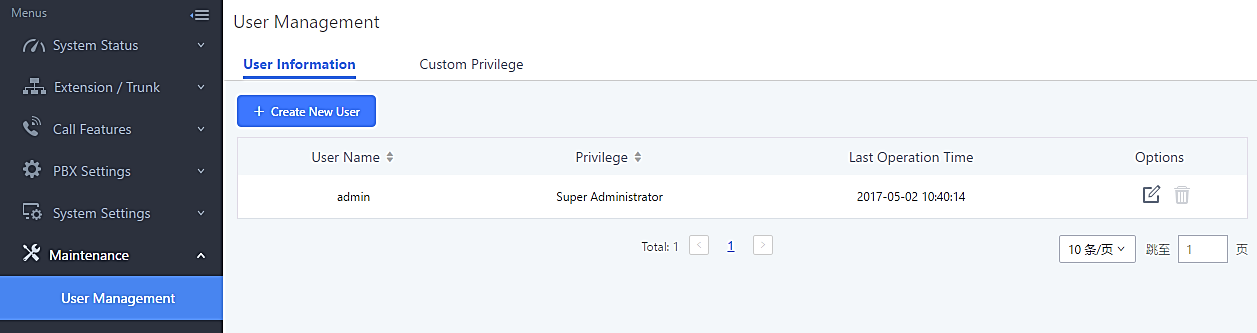
User Information
When logged in as Super Admin, click on ![]() to create a new account for Web GUI user. The following dialog will prompt. Configure the parameters as shown in below table.
to create a new account for Web GUI user. The following dialog will prompt. Configure the parameters as shown in below table.
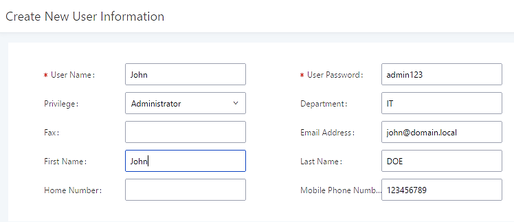
Username | Configures a username to identify the user which will be required in Web GUI login. Letters, digits and underscore are allowed in the username. |
User Password | Configures a password for this user which will be required in Web GUI login. Letters, digits, and underscore are allowed. |
Privilege | This is the role of the Web GUI user. Currently only “Admin” is supported when Super Admin creates a new user. |
Department | Enters the necessary information to keep a record for this user. |
Fax | |
Email Address | |
First Name | |
Last Name | |
Home Number | |
Phone Number |
Table 315: Create New User
Once created, the Super Admin can edit the users by clicking on ![]() or delete the user by clicking on
or delete the user by clicking on ![]() .
.
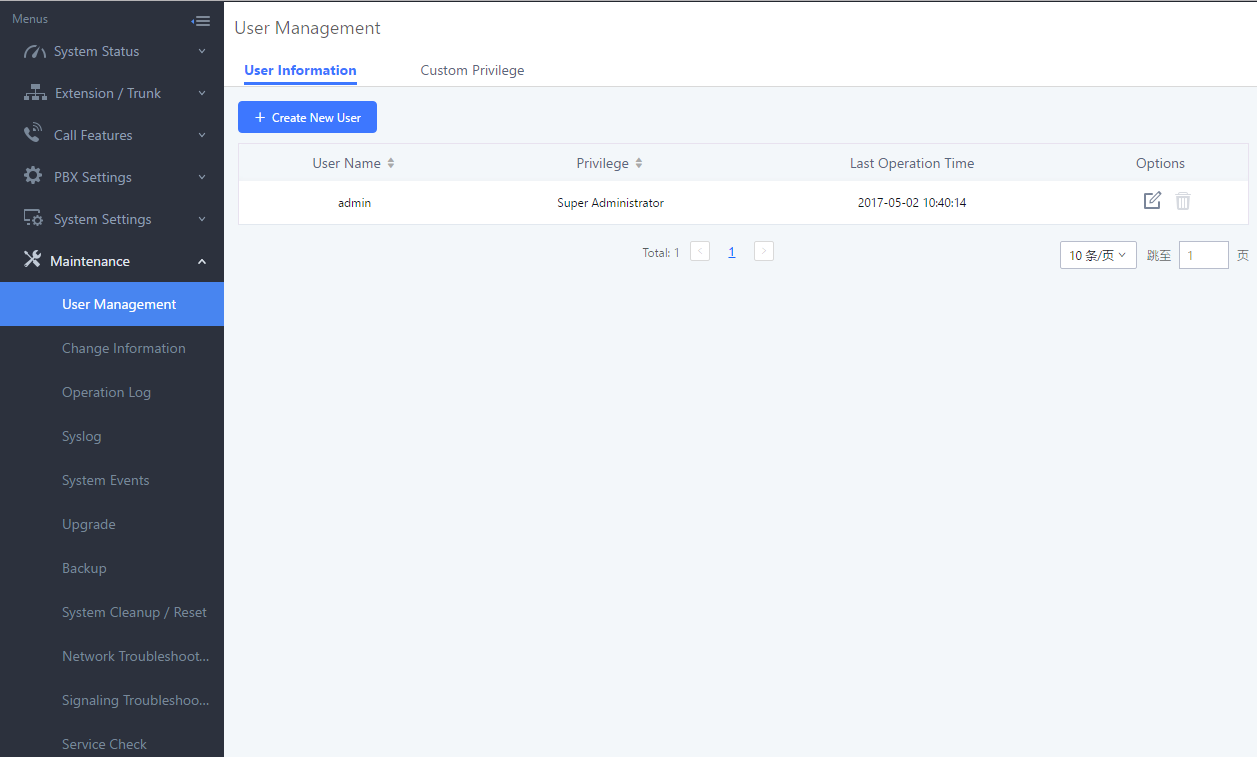
Custom Privilege
Four privilege levels are supported:
- Super Administrator
- This is the highest privilege. Super Admin can access all pages on UCM6510 Web GUI, change configuration for all options and execute all the operations.
- Super Admin can create, edit and delete one or more users with “Admin” privilege
- Super Admin can edit and delete one or more users with “Consumer” privilege
- Super Admin can view operation logs generated by all users.
- By default, the user account “admin” is configured with “Super Admin” privilege and it is the only user with “Super Admin” privilege. The Username and Privilege level cannot be changed or deleted.
- Super Admin could change its own login password on Web GUI🡪Maintenance🡪Change Information page.
- Super Admin could view operations done by all the users in Web GUI🡪Maintenance🡪Operation Log.
- Administrator
- Users with “Admin” privilege can only be created by “Super Admin” user.
- “Admin” privilege users are not allowed to access the following pages:
Maintenance🡪Upgrade
Maintenance🡪Cleaner
Maintenance🡪Reset/Reboot
Maintenance🡪User Management🡪Operation Log
- “Admin” privilege users cannot create new users for login.
Note: By default, administrator accounts are not allowed to access backup menu, but this can be assigned to them by navigating to Maintenance🡪User Management🡪Custom Privilege🡪Edit Admin Account and giving the account the Backup privilege.
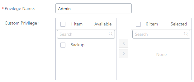
- Consumer
- A user account for Web GUI login is created automatically by the system when a new extension is created.
- The user could log in the Web GUI with the extension number and password to access user information, extension configuration, CDR of that extension, personal data and value-added features. For more details; please refer to User Portal Guide.
- The SuperAdmin user can click on the “General_User” in order to enable/disable the custom privilege of deleting their own recording files in user level login.
- General_User also has allowed to change Auth ID and SIP Password and Allow to Enable Voicemail options.
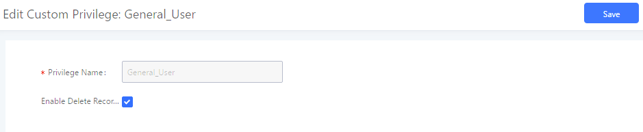
The Super Admin user can create users with different privileges. 23 modules are available for privilege customization.
- API Configuration
- Backup
- Callback
- Call Queue
- CDR Recording Files
- CDR Records
- CDR Statistics
- Conference
- Dial By Name
- DISA
- Emergency Calls
- Event List
- Extensions
- Outbound Routes
- Inbound Routes
- Fax/T.38
- Feature Codes
- IVR
- Paging/Intercom
- Parking Lot
- Pickup Groups
- PMS – Wakeup Service
- Ring Groups
- SCA
- Speed Dial
- System Status
- System Events
- Time Settings
- Video Conference
- Voicemail
- Voice Prompt
- Wakeup Service
- Zero Config
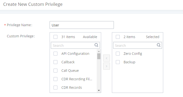
System administrators can create custom privilege sets which can be assigned to created users.
Concurrent Multi-User Login
While UCM supports simultaneous user logins, if different users are modifying the same option or doing the same operation, the following error message may appear:

Login Settings
Change Password
After logging in the Web GUI for the first time, it is highly recommended for users to change the default password “admin” to a more complicated password for security purpose. Follow the steps below to change the Web GUI access password.
- Go to Web GUI🡪Maintenance🡪Login Settings page.
- Enter the old password first.
- Enter the new password and retype the new password to confirm.
Note: If PBX Settings🡪General Settings🡪Enable Strong Password is toggled on, the minimum password requirements are as follows:
- Must contain at least one number.
- Must contain at least one uppercase letter, lower case letter, OR special character.
- Configure Email Address for account recovery purpose.
- Click on “Save”. User will be automatically logged out.
- Once the web page comes back to the login page again, enter the username “admin” and the new password to login.
|
Enter Old Password |
Enter the Old Password for UCM6510 |
|
Enter New Password |
Enter the New Password for UCM6510 |
|
Retype New Password |
Retype the New Password for UCM6510 |
|
Email Address |
Configure an email address for account recovery purposes. |
Change Username
UCM6510 allows users now to change Super Administrator username.
|
Change Username |
Enabling the change username option |
|
Please enter the new username |
Enter the new username |
Login Security
After the user logs in the UCM6510 Web GUI, the user will be automatically logged out after certain timeout, or he/she can be banned for a specific period if the login timeout is exceeded. Those values can be specified under UCM6510 web GUI🡪Maintenance🡪 Login Settings 🡪Login Security page.
The “User Login Timeout” value is in minute and the default setting is 10 minutes. If the user does not make any operation on Web GUI before the timeout, the user will be logged out automatically. After that, the Web GUI will be redirected to the login, and the user will need to enter the username and password again to log back in.
If set to 0, there will be no timeout period, and users can remain logged in for an indefinite period of time.
“Maximum number of login attempts” protects the UCM against brute force authentication attempts. If the number of attempts from an IP address exceeds the configured value, it will be blacklisted, and the IP address will be banned based on the configured User ban period. Default value is 5.
“User ban period” specifies the amount of time (in minutes) that an IP address is banned from attempting to log into the UCM system. A value of 0 indicates a permanent ban. Default value is 5.
“Login Banned User List” shows the list of IP addresses banned from the UCM.
“Login Whitelist” Users can create a list of IP addresses that will not be banned even if they exceed the maximum number of failed login attempts.
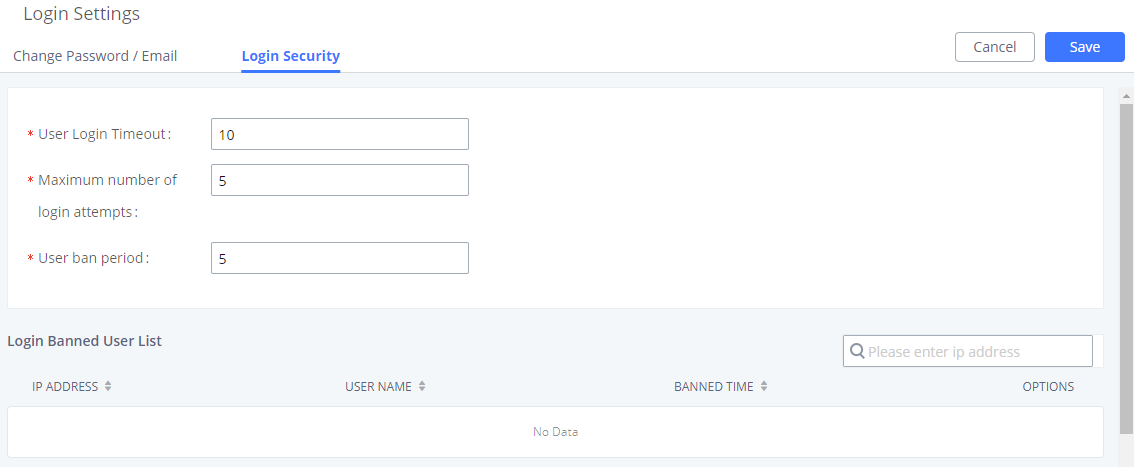
Operation Log
The Operation Log lists all activities done by all users that have accessed the UCM web portal. This page is found under Maintenance🡪Operation Log.
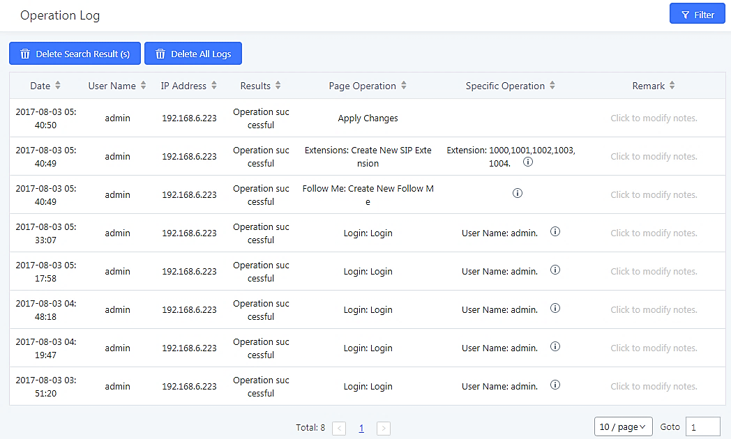
The operation log can be sorted and filtered for easy access. Click on the header of each column to sort based on those columns. For example, clicking on “Date” will sort the logs according to operation date and time. Clicking on “Date” again will reverse the order.
|
Date |
The date and time when the operation is executed. |
|
Username |
The username of the user who performed the operation. |
|
IP Address |
The IP address from which the operation is made. |
|
Results |
The result of the operation. |
|
Page Operation |
The page where the operation is made. For example, login, logout, delete user, create trunk and etc. |
|
Specific Operation |
Click on |
|
Remark |
Allows users to add notes and remarks to each operation |
User could also filter the operation logs by time condition, IP address and/or username. Configure these conditions and then click on ![]() .
.
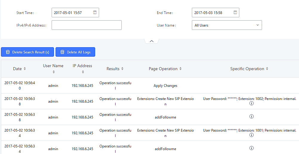
In the figure above, operations made by user “support” on device with IP 192.168.40.173 from 2014-11-01 00:00 to 2014-11-06 15:38 are filtered out and displayed.
To delete operation logs, users can either filter out specific operation logs then click on the ![]() button to delete the filtered results or click on the
button to delete the filtered results or click on the ![]() button to delete all operation logs.
button to delete all operation logs.
Upgrading
The UCM6510 can be upgraded to a new firmware version remotely or locally. This section describes how to upgrade your UCM6510 via network or local upload.
Upgrading via Network
The UCM6510 can be upgraded via TFTP/HTTP/HTTPS by configuring the URL/IP Address for the TFTP/HTTP/HTTPS server and selecting a download method. Configure a valid URL for TFTP, HTTP or HTTPS; the server name can be FQDN or IP address.
Examples of valid URLs:
firmware.grandstream.com/BETA
The upgrading configuration can be accessed via Web GUI🡪Maintenance🡪Upgrade.
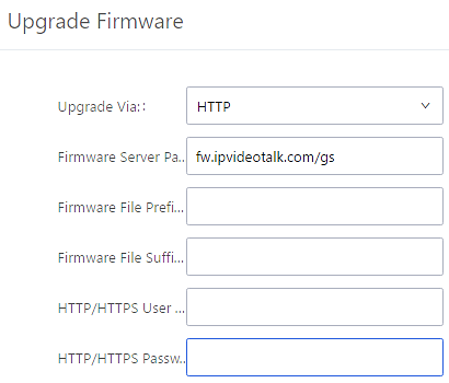
|
Upgrade Via |
Allow users to choose the firmware upgrade method: TFTP, HTTP or HTTPS. |
|
Firmware Server Path |
Define the server path for the firmware server. |
|
Firmware File Prefix |
If configured, only the firmware with the matching encrypted prefix will be downloaded and flashed into the UCM6510. |
|
Firmware File Suffix |
If configured, only the firmware with the matching encrypted postfix will be downloaded and flashed into the UCM6510. |
|
HTTP/HTTPS Username |
The username for the HTTP/HTTPS server. |
|
HTTP/HTTPS Password |
The password for the HTTP/HTTPS server. |
Please follow the steps below to upgrade the firmware remotely.
- Enter the firmware server path under Web GUI🡪Maintenance🡪Upgrade.
- Click on “Save”. Then reboot the device to start the upgrading process.
- Please be patient during the upgrading process. Once done, a reboot message will be displayed in the LCD.
- Manually reboot the UCM6510 when it is appropriate to avoid immediate service interruption. After it boots up, log in the Web GUI to check the firmware version.
Upgrading via Local Upload
If there is no HTTP/TFTP server, users could also upload the firmware to the UCM6510 directly via Web GUI. Please follow the steps below to upload firmware locally.
- Download the latest UCM6510 firmware file from the following link and save it in your PC.
- http://www.grandstream.com/support/firmware
- Log in the Web GUI as administrator in the PC.
- Go to Web GUI🡪Maintenance🡪Upgrade, upload the firmware file by clicking on “Choose file to upload” and select the firmware file from your PC. The default firmware file name is ucm6510fw.bin

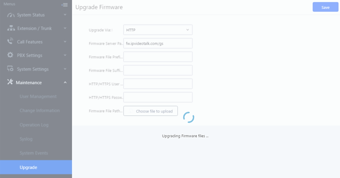
- Wait until the upgrading process is successful and a window will be popped up in the Web GUI.
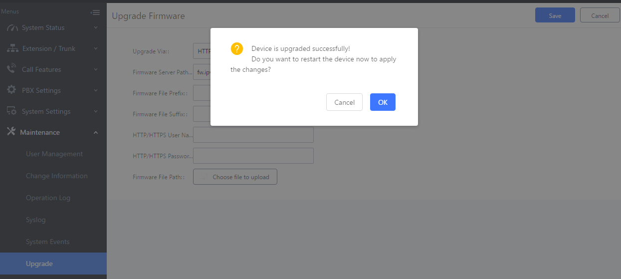
- Click on “OK” to reboot the UCM6510 and check the firmware version after it boots up.
No Local Firmware Servers
Service providers should maintain their own firmware upgrade servers. For users who do not have TFTP/HTTP/HTTPS server. Some free windows version TFTP servers are available for download from
https://www.solarwinds.com/products/freetools/free_tftp_server.aspx
Please check our website at https://www.grandstream.com/support/firmware for latest firmware.
Instructions for local firmware upgrade via TFTP:
- Unzip the firmware files and put all of them in the root directory of the TFTP server;
- Connect the PC running the TFTP server and the UCM6510 to the same LAN segment;
- Launch the TFTP server and go to the File menu🡪Configure🡪Security to change the TFTP server’s default setting from “Receive Only” to “Transmit Only” for the firmware upgrade;
- Start the TFTP server and configure the TFTP server in the UCM6510 web configuration interface;
- Configure the Firmware Server Path to the IP address of the PC;
- Update the changes and reboot the UCM6510.
End users can also choose to download a free HTTP server from https://httpd.apache.org/ or use
Microsoft IIS web server.
Backup
The UCM6510 configuration can be backed up locally or via network. The backup file will be used to restore the configuration on UCM6510 when necessary.
Backup/Restore
To create backups, navigate to Maintenance🡪Backup🡪Backup/Restore and click on the Backup button to start the process.
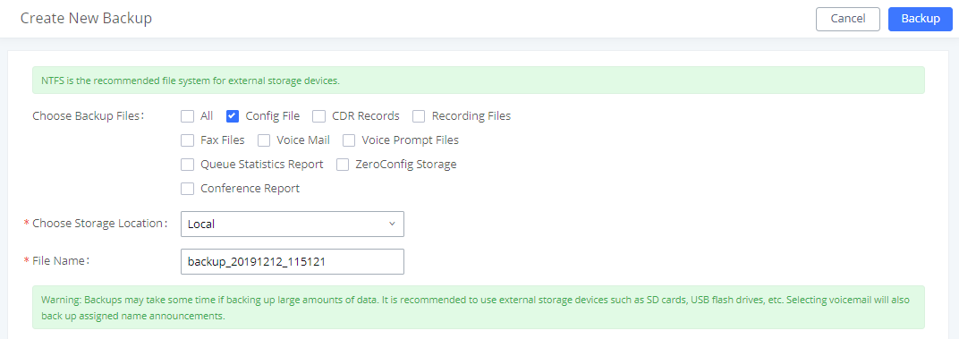
- Choose the files to be included in the backup.
- Choose where to store the backup file: USB Disk, SD Card, Local or NAS.
- Name the backup file.
- Click on “Backup” to start backup.
Once the backup is done, it will appear in the List of Previous Configuration Backups. From this list, users can download, restore, and delete backups. Users can download ![]() , restore
, restore ![]() , or delete
, or delete ![]() it from the UCM6510 internal storage or the external device.
it from the UCM6510 internal storage or the external device.
Users can also upload UCM backups from their PC to the UCM by clicking on the Upload button.
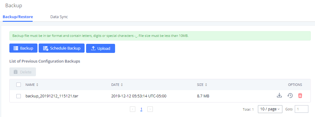
The ![]() option allows UCM to perform periodic backups to USB disks, SD cards, SFTP servers, or NAS servers. Users can configure the hour and frequency of the periodic backup.
option allows UCM to perform periodic backups to USB disks, SD cards, SFTP servers, or NAS servers. Users can configure the hour and frequency of the periodic backup.
Users can test connections with SFTP servers.
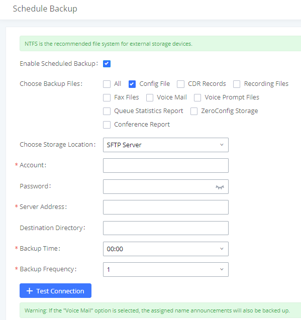
Data Sync
Besides local backup, users can back up call recordings, voicemail, CDR, and fax daily to an SFTP server via the Data Sync feature in the Maintenance🡪Backup🡪Data Sync page.
Special characters such as @ and periods (.) are supported, allowing users to use email addresses as SFTP account usernames and to specify destination directories on the SFTP server. If a specified directory does not exist on the SFTP server, the UCM will create it automatically.
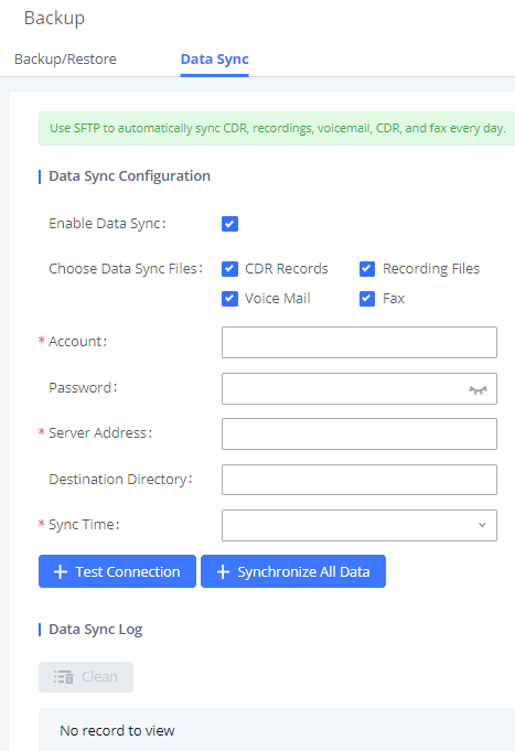
|
Enable Data Sync |
Enable the auto backup function. The default setting is “No”. |
|
Account |
Enter the Account name on the SFTP backup server. |
|
Password |
Enter the Password associate with the Account on the SFTP backup server. |
|
Server Address |
Enter the SFTP server address. |
|
Destination Directory |
Specify the directory in SFTP server to keep the backup file. Format: ‘xxx/xxx/xxx’, If this directory does not exist, UCM will create this directory automatically. |
|
Sync Time |
Enter 0-23 to specify the backup hour of the day. |
Before saving the configuration, users can click on the Test Connection button to verify connection status. Clicking on the Synchronize All Data button will manually start a data sync.
Save the changes and all the backup logs will be listed on the web page.
Restore Configuration from Backup File
To restore the configuration on the UCM6510 from a backup file, users could go to Web GUI🡪Maintenance🡪Backup🡪Backup/Restore.
- A list of previous configuration backups is displayed on the web page. Users could click on of the desired backup file to override the UCM current settings with the backup’s.
- If users have other backup files on PC to restore on the UCM6510, click on “Upload Backup File” first and select it from local PC to upload on the UCM6510. Once the uploading is done, this backup file will be displayed in the list of previous configuration backups for restore purpose. Click on to restore from the backup file.
- Users can restore backup files located on SD cards, USB disks, or NAS servers.
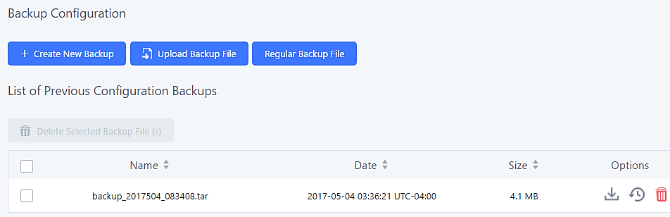
System Cleanup/Reset
Reset and Reboot
Users could perform reset and reboot under Web GUI🡪Maintenance🡪Reset and Reboot.
To factory reset the device, select the Type. There are two different reset types.
- User Data
Voicemail, call recordings, voice prompts, Music on Hold files, CDR, and backup files will be erased.
- All
All files will be erased, and all settings will be reset to factory settings.
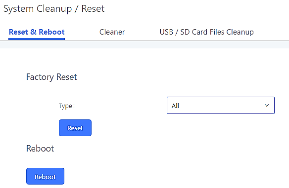
Cleaner
The UCM can be configured to delete files, CDR, voicemail, and calls statistic reports on a regular basis. This feature can be accessed from the Maintenance🡪System Cleanup/Reset🡪Cleaner page.
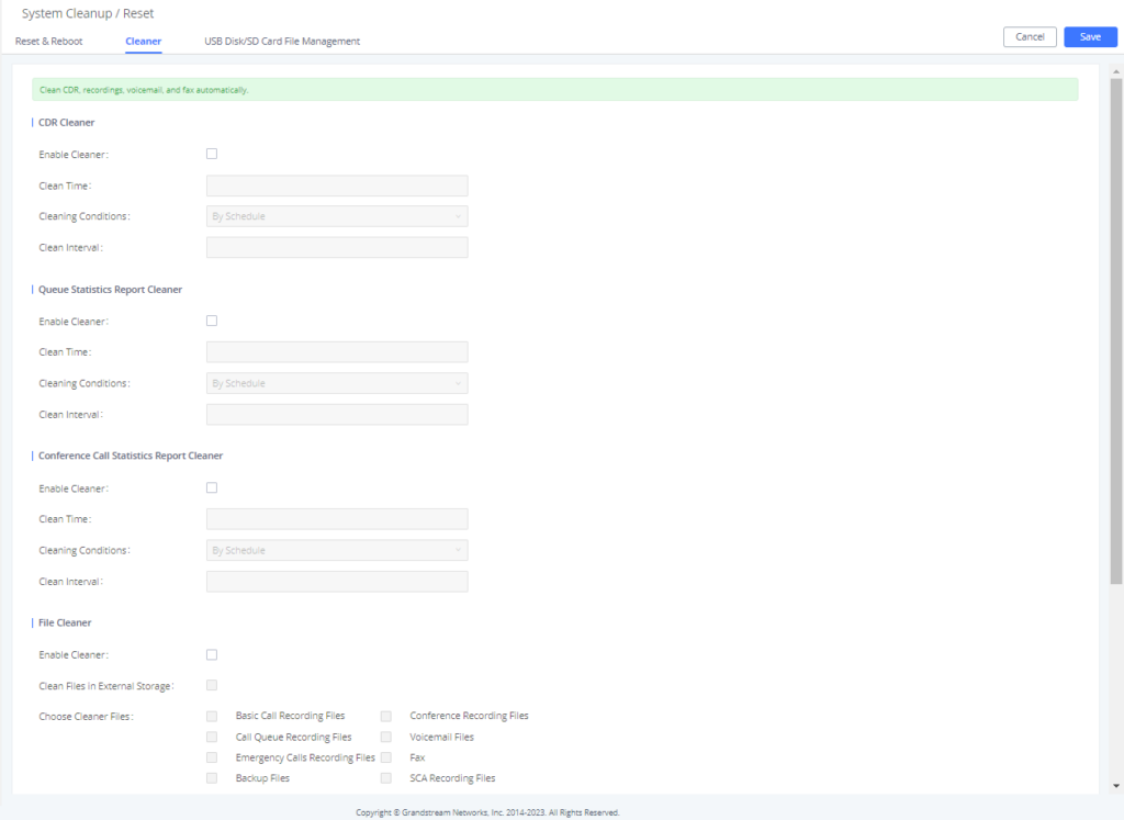
CDR Cleaner | |
Enable Cleaner | Enable the CDR Cleaner function. |
Clean Time | Enter 0-23 to specify the hour of the day to clean up CDR. |
Cleaning Conditions |
|
Clean Interval | Enter 1-30 to specify the day of the month to clean up CDR when By Schedule is selected as Cleaning Conditions. |
Max Entries | Set the maximum number of CDR entries to keep when Keep Last X Records is selected as Cleaning Conditions. Default is 50000. Valid range: |
Keep Last X Days | Enter the number of days of call log entries to keep when Keep Last X days is selected as Cleaning Conditions. Default is 30. Valid range: 1 – 100. |
Queue Statistics Report Cleaner | |
Enable Cleaner | Enable scheduled queue log cleaning. |
Clean Time | Enter the hour of the day to start the cleaning. The valid range is 0-23. |
Cleaning Conditions |
|
Clean Interval | Enter how often (in days) to clean queue logs when By Schedule is selected as Cleaning Conditions. The valid range is 1-30. |
Max Entries | Set the maximum number of Queue Statistics Report entries to keep when Keep Last X Records is selected as Cleaning Conditions. Default is 50000. Valid range: |
Keep Last X Days | Enter the number of days of Queue Statistics Report entries to keep when Keep Last X days is selected as Cleaning Conditions. Default is 30. Valid range: 1 – 730. |
Conference Call Statistics Report Cleaner | |
Enable Cleaner | Enable scheduled conference log cleaning. |
Clean time | Enter the hour of the day to start the cleaning. The valid range is 0-23. |
Cleaning Conditions |
|
Clean Interval | Enter how often (in days) to clean queue logs when By Schedule is selected as Cleaning Conditions. The valid range is 1-30. |
Max Entries | Set the maximum number of CDR Conference Call Statistics Report entries to keep when Keep Last X Records is selected as Cleaning Conditions. Default is 50000. Valid range: |
Keep Last X Days | Enter the number of days of Conference Call Statistics Report entries to keep when Keep Last X days is selected as Cleaning Conditions. Default is 30. Valid range: 1 – 100. |
File Cleaner | |
Enable Cleaner | Enabling files cleaning. |
Clean Files in External Device | If enabled the files in external device (USB/SD card) will be automatically cleaned up as configured. |
Choose Cleaner File | Select the files for system automatic clean.
|
Clean Time | Enter the hour of the day to start the cleaning. The valid range is 0-23. |
Cleaning Conditions |
|
File Clean Interval | Enter 1-30 to specify the day of the month to clean up the files. |
File Clean Threshold | Enter the internal storage disk usage threshold (in percent). Once this threshold is exceeded, the file cleanup will proceed as scheduled. Valid range is 0-99. |
Keep Last X Days | Automatically delete all recordings older than this x days when the threshold is reached. If not set, all data is cleared. Valid range: 1 – 100. |
Cleaner Log | |
Cleaner Log | Clicking on the Clean button will clear the cleaner log. |
All the cleaner logs will be listed on the bottom of the page.
USB Disk/SD Card File Management
From this page, users can view, download, and delete files on USB disks and SD cards.
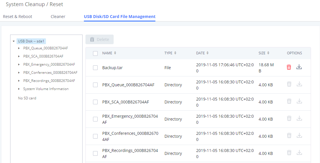
|
Current Path |
Displays the current path. |
|
Directory |
Select the directory user want to clean. |
|
Delete Selected File |
Select multiple entries to delete from USB or SD card. |
System Recovery
In the scenario where the UCM cannot be accessed via web or SSH, users can try to recover the system by resetting the system or upgrading system firmware via the UCM’s recovery mode.
To access recovery mode, follow these steps:
- Disconnect the power cable from the UCM and keep the network cable connected.
- Press and hold the reset button located on the back of the UCM.
- Reconnect the power cable while holding the reset button.
- Keep holding until a click sound is heard. Release the reset button.
- The UCM’s LCD should now display “Recovery Mode” and an IP address.
Once at this stage, the administrator can access the recovery mode web portal by typing in either the IP0 address (typically WAN) or IP1 address (typically LAN) into a browser address bar. The following page should appear:
Enter the super admin’s login credentials and click on the Login button:
From here, the user can either upload a firmware file, factory reset or just reboot the device.
Syslog
On the Maintenance🡪Syslog page, users can configure the UCM to send syslog to a remote server. By default, ERROR logs are enabled for all PBX modules. Additional syslog levels are WARN, NOTICE, DEBUG, and VERBOSE.
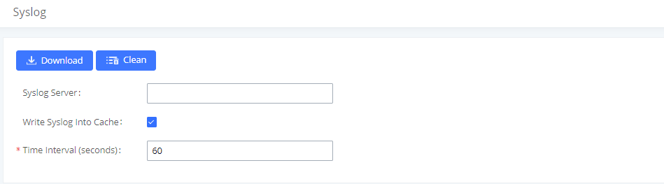
|
Syslog Server |
The URL/IP address for the syslog server. |
|
Write Syslog into Cache |
If enabled, syslog will be sent to and cached in system memory until it is written to internal storage at the specified time interval. Enabling this helps to improve the lifespan of the UCM’s flash storage. |
|
Time Interval (seconds) |
Configures the period of time that must pass before writing the cached syslog to internal storage. Setting the time interval too high may result in lost syslog data due to the low saving frequency. |
- pbx: This module is related to general PBX functions.
- chan_sip: This module is related to SIP calls.
- chan_dahdi: This module is related to analog calls (FXO/FXS).
- app_meetme: This module is related to Conference room.
Network Troubleshooting
The Network Troubleshooting page under Maintenance allows users to start network captures and ping/traceroute remote hosts.
Ethernet Capture
Captured traces can be downloaded for analysis.
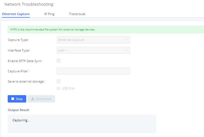
|
Interface Type |
Select the network interface to monitor. |
|
Check this box to save the capture files in the SFTP server. Please make sure the configuration of data synchronization works before. | |
|
Capture Filter |
Enter the filter to obtain the specific types of traffic, such as (host, src, dst, net, proto…). |
|
Save to External Storage |
Check this box to activate storage of the capture either on the USB or SD Card. |
|
Start |
Click to start the trace. |
|
Stop |
Click to stop the trace. |
|
Download |
Click to download the trace if trace is stored locally. |
The output result is in .tgz format, and users will need to use a compression tool such as WinRAR or 7-zip to unzip the .pcap file.
IP Ping
Enter the hostname or IP address and click on the Start button. The ping process can be viewed from the Output Result window at the bottom of the page.
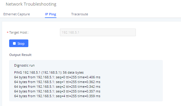
Traceroute
Enter the hostname or IP address and click on the Start button. The ping process can be viewed from the Output Result window at the bottom of the page.
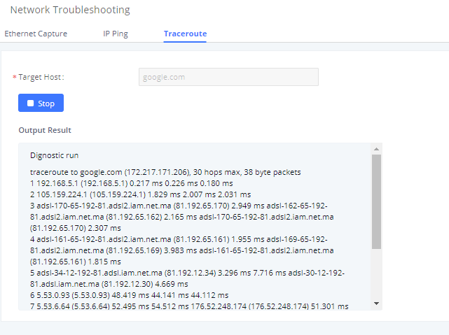
Signaling Troubleshooting
PRI/SS7/MFC/R2 Signaling Trace
Please see section [Digital Trunk Troubleshooting].
Analog Record Trace
- Analog Record Trace
Analog record traces are used to troubleshoot analog trunk issues (e.g., CID detection for incoming calls from an analog trunk.
To capture analog record traces:
- Select FXO or FXS for “Record Ports”. If the issue happens on FXO 1, select FXO port 1 to record the trace.
- Select “Record Direction”.
- Select “Record File Mode” to separate the record per direction or mix.
- Click on “Start”.
- Make a call via the analog port that has the issue.
- Once done, click on “Stop”.
- Click on “Download” to download the analog record trace.
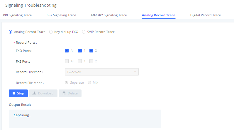
- Key Dial-up FXO
Users can configure a PSTN number in the External Number field to send test calls to and troubleshoot issues related to the used analog trunk. To use this:
- Configure analog trunk on UCM, including outbound route.
- Enter a reachable external number in “External Extension”.
- Press “Start” button. The call will be initiated to the external number.
- Answer and finish the call before pressing “Stop” button.
- The trace will be available for analysis to download after output result shows “Done! Click on Download to download the captured packets”.
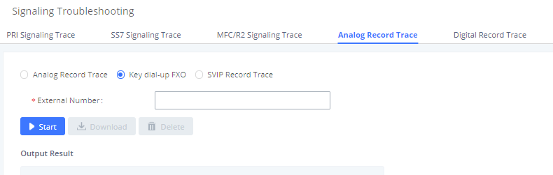
- SVIP Record Trace
Users can capture an SVIP record trace for specific FXO/FXS ports.
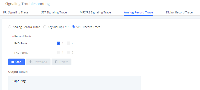
E&M Immediate Record Trace
To capture an E&M record trace, navigate to Signaling Troubleshooting->Digital Record Trace and configure the Record Direction and Record File Mode options to the desired values. Click on the Start button to start capturing.
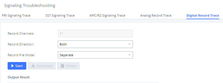
Service Check
Service Check will cause the UCM to periodically send SIP OPTIONS to the Asterisk server to check on functionality.
Check Cycle is the frequency (in seconds) at which to check the Asterisk server for issues.
Check Times is the maximum number of failed checks that can occur before the UCM is restart, and a coredump file is generated. Generated coredump files can be sent to Grandstream Technical Support for analysis and troubleshooting.
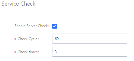
Network Status
Users can navigate to System Status🡪Network Status to view the UCM’s active network connections. If users are experiencing connection issues to specific services, they can view this page for troubleshooting.
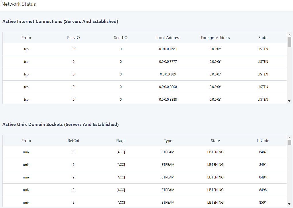
Change Log
This section documents significant changes from previous versions of the UCM6510 user manual. Only major new features or major document updates are listed here. Minor updates for corrections or editing are not documented here.
Firmware Version 1.0.20.52
- Several system and security optimizations
Firmware Version 1.0.20.49
- Several system optimizations
- Added the ability to filter CDR by extension number. [CDR]
- Added “Send Voicemail Email Notification” option to extension settings. [Create New SIP Extension]
- Increased the input timeout period of transferring via feature code from 3 seconds to 6 seconds. [Feature Codes]
- Added the “Discard Remote Hold Signal” option to the PBX Settings→Interface Settings→Edit Digital Port →Advanced Settings page. If enabled, the remote party’s hold signaling will be ignored. [Digital Hardware Configuration]
- Added agent name information to the User Portal queue page. [Switchboard]
- Improved security processes.
- Added the “Ignore 180 Response” option to the PBX Settings→SIP Settings→Misc. If enabled, 180 ringing will be ignored if a 183 response is received. [SIP Settings/Misc]
- Added the Colombia/Panama/Ecuador time zone.
- Added support for importing account info into GRP endpoints via CSV. [Uploading Devices List]
- Increased firmware file upload size limit to 1 GB. [Upgrading via Local Upload]
Firmware Version 1.0.20.48
- Added support for batch editing extension options Send Voicemail to Email and Keep Voicemail after Emailing.
- The contact header in outgoing calls via register trunks will now use the Username value instead of the From User value.
Firmware Version 1.0.20.47
- BLF color will now change to red if the monitored extension enables DND.
- Added ability to configure DOD for outbound routes.
- Diversion header will now include public IP information.
- Added Enable Remote SSH via GDMS option.
- Added the “None” option to the extension board setting Mode dropdown list.
Firmware Version 1.0.20.44
- Added support for E.164 format in the Emergency Calls CID field.
Firmware Version 1.0.20.43
- Added option “Enable T.38 UDPTL” to VoIP trunk settings page to toggle T.38 support for individual trunks. [T.38 UDPTL]
- Added option to play a Satisfaction Survey prompt after a call to measure customer service satisfaction. [Satisfaction Survey Prompt]
- Added ability to customize the virtual queue callback keys that will be prompted. [Virtual Queue Callback Key Settings]
- No major changes.
- Added support for FQDN and IP address format in the Realm for Digest Authentication field. [Realm For Digest Authentication]
- Added Enable Record Feature Code option to queue settings. [Enable Record Feature Code]
- Added the ability to restrict calls between extensions. [RESTRICT CALLS]
- Added the option to select the transport method information displayed in extension information emails in the System Settings🡪Email Settings🡪Email Template🡪Edit Extension Template page. [Email Templates]
- Added configuration options User Information in Fax Header and Fax Header Information to the Call Features Fax/T.38 Fax Settings page. This will give users the option to send a special header in SIP fax messages. [User Information in Fax Header]
- Added command to delete call recordings after downloading them. [Recapi]
- Added DTMF Start Threshold and DTMF End Threshold options to the PBX Settings Interface Settings DAHDI Settings page. [DAHDI Settings]
- Added External Disk Status alert event for monitoring external storage connection status. [External Disk Status]
- The language of column titles in exported CDR reports and statistics reports will now be based on the UCM’s display language. [Downloaded CDR File]
- Added 3 more room statuses and corresponding prompts: Room Cleared, Room Not Cleaned, and Room Closed. [Room Status]
- Updated Hmobile Mini Bar request. [HMobile PMS Connector]
- Added the Ringback Tone option for inbound calls. [special ringing tone]
- The value configured in the Server User Agent Value field will now replace the whole User-Agent header value instead of just the “UCM6xxx” part. [Server User Agent]
- Added the ability to import/export a CSV file of the configured DODs for a specified trunk. [DOD Import/Export]
- Added more details to HA-related syslog. [Syslog]
- To improve UCM flash storage lifespan, syslog will no longer be written to UCM internal storage if a syslog server is configured. [Syslog]
- Added parameters x-gscall-type and x-gs-group-name to the ACK From header sent by the UCM for calls made to ring groups and queues to improve compatibility with non-Grandstream endpoints.
- Added GMT-4:00 (Atlantic Standard Time) and GMT+1:00 (Casablanca) to Time Settings [Time Zone]
- Added HTTPS API commands to list, add, remove, and update analog trunks, SLA trunks, and digital trunks. [HTTPS API]
- Added HTTP/HTTPS protocol option for sending real-time CDR output. [Delivery Method]
- Hidden the option “Allow Guest Calls”.
- No major changes.
- No major changes.
- Increased the maximum limit of IVR entries to 500 and inbound routes to 5000. [IVR] [Inbound Routes]
- Added support for full compliance with Kari’s law and Ray Baum’s act. [EMERGENCY]
- Increased the maximum number of outbound routes to 500. [Outbound Routes]
- Increased the maximum limit of SIP trunks to 200. [VOIP TRUNKS]
- [Announcement]
- Added Announcement feature. [Announcement]
- [Backup/Restore]
- Added NAS as a backup/restore location. [Backup/Restore]
- [Conference]
- Added conference contact groups. [Contact Group]
- Added conference call statistics and reports. [Conference Call Statistics]
- [CRM]
- Added support for Zoho CRM v2 API. [ZohoCRM]
- [GDMS]
- Added GDMS SIP account syncing. [GDMS SETTINGS]
- [HTTPS API]
- Add a new HTTPS API. [HTTPS API (New)]
- [Maintenance]
- Added the ability to download files on external storage from the USB Disk/SD Card File Management page. [USB Disk/SD Card File Management]
- Added several more conditions for cleaning files and CDR. [Cleaner]
- [Queue]
- Added the ability to customize the keys used for virtual queue. [Virtual Queue Callback Key Settings]
- Improved queue statistics page. [Queue Statistics]
- Added a Welcome Prompt option to the Edit Queue page. [Welcome Prompt]
- Added QueueMetrics support. [QUEUEMETRICS INTEGRATION]
- [Paging]
- Added Private Intercom paging type (GSC3510 only). [Configure Private Intercom]
- [PMS]
- Added the ability to backup voicemail recordings upon guest check-out. [Connecting to PMS]
- [Call Routing]
- Added Outbound Route CID option to the Extensions/Trunk🡪Outbound Routes page. [Outbound Route CID]
- [VoIP Trunks]
- Users can now dial into IPVT meeting rooms via peer trunks. [IPVIDEOTALK MEETINGS]
- Added support for DOD to be assigned to UCM’s Fax Sending feature. [Direct Outward Dialing (DOD) via VoIP Trunks]
- [Zero Config]
- Auto Discover can now search for devices located on subnets added to the Subnet Whitelist. [Discovery]
Other Enhancements
- [Active Calls]
- Updated Parked calls which will now be displayed in the Active Calls page. [Active Calls Status]
- [AMI]
- AMI username can no longer exceed 64 characters. [ASTERISK MANAGER INTERFACE (RESTRICTED ACCESS)]
- [Announcement Center]
- Announcement Center group name and numbers now have a character limit of 64. [
- Group Setting]
- [Basic Calls]
- Added International Call Prefix. [PBX SETTINGS]
- After an attended transfer is completed, endpoints will now be updated with the CID of the other party instead of keeping the transferor’s CID.
- Added Block collect calls option in SIP settings🡪General settings. [Block Collect Calls]
- [Backup/Restore]
- Added event logs and email notifications for scheduled SFTP backup and data sync results. [Alert Events List]
- [Call Completion]
- Updated the number of CC agents to be limited by the extensions allowed number of concurrent registrations. [CC Mode] [BUSY CAMP-ON]
- [CDR]
- Added Extension Groups as a CDR filter. [Table 149: CDR Filter Criteria]
- [Conference]
- Added a field to configure the Kick Prompt Interval. [Kick Warning Interval]
- Added support for Conference participant names to be announced when joining/leaving the conference even when the conference is on hold. [Announce Callers]
- Extended the Meeting duration to be scheduled up to 8 hours. [Meeting Duration]
- Conference extension number can no longer be used as the conference password if Strong Password is enabled. [Password]
- [CRM]
- Added “Add Unknown Number” option for ACT! CRM. [ACT! CRM]
- Added https://www.zohoapis.eu to the ZohoCRM Server Address dropdown list. [ZohoCRM]
- [Dial by Name]
- Added the ability to upload a custom Dial by Name prompt. [Custom Prompt]
- [Digital Trunks]
- Direct Callback option will be hidden if E&M Immediate or E&M Wink is selected for the Edit T1 Port🡪Signaling. [Direct Callback]
- [DOD]
- Added DOD names and numbers character limit to 32. [Direct Outward Dialing (DOD) via VoIP Trunks]
- [Email Settings]
- Added new variable ${CONFR_MEMBERS}, which shows conference participant details. [Email Templates]
- Added the following email type filters to the Email Send Log page: Send Fax, Call Queue Statistics, Conference Report. [Email Send Log]
- [Emergency Calls]
- Users can now strip the same amount of numbers as the emergency number length itself. [Strip]
- [Eventlist]
- Added a search bar for eventlists. [Event List]
- [Extensions]
- The Extension and Auth ID fields now support plus signs (+). [Extension][Auth ID]
- Enable CC option added as batch edit extension option. [Enable CC]
- Subnet mask can now be specified when configuring subnets that can register to the extension. [ACL Policy] [Local Network Address]
- [GS Wave Web]
- A conference participant’s CID number will now be displayed instead of extension number if configured. [Wave WebRTC Video Calling & Conferencing]
- Improved extension searching when transferring. [Wave WebRTC Video Calling & Conferencing]
- An error message will now appear when the maximum number of allowed registrations has been reached. [Wave WebRTC Video Calling & Conferencing]
- Hosts can now generate a link that can be used to invite others to the conference. [Wave WebRTC Video Calling & Conferencing]
- [IVR]
- Added support to upload more than one welcome prompt for IVR. [Welcome Prompt]
- [LDAP]
- Plus signs (+) is now supported when creating contacts and receiving calls with “+” in the CID. [LDAP Phonebook]
- LDAP Client CA Cert field no longer supports .ca file uploads. The following file types are supported: .crt .der .pem. [LDAP Client CA cert]
- The Username field will no longer require “cn=” to precede username. [Username]
- Character limit changed for the following fields:
- LDAP Server🡪Root Password: 32 [LDAP Server]
- LDAP Server🡪Root DN: 64 [LDAP Server]
- Phonebook Download Configurations🡪Username: 64 [Username]
- LDAP now supports downloading phonebooks from domains. [Server Address]
- Added space support to the LDAP Client Username. [Username]
- [Maintenance]
- Added Conference Call Statistics Report Cleaner. [Conference Call Statistics Report Cleaner]
- [OpenVPN®]
- Added option Allow Weak SSL Ciphers. [Allow Weak SSL Ciphers]
- [Paging]
- Added an option to allow scheduled paging to play during holidays. [Include Holidays]
- “=” is no longer supported in the Alert-Info Header field. [Paging/Intercom Group Settings]
- [Parking]
- Ring All Callback on Timeout will not be available if Forward to Destination on Timeout is enabled. [Ring All Callback on Timeout]
- The Failover Destination field now has a character limit of 32. [Failover Destination]
- [PMS]
- The Username and Guest Category Code columns in the Room Status page can now be sorted. [Room Status]
- [Queue]
- Agents can now view recordings of their calls in their user portal. [USER PORTAL]
- A queue can now have 3 chairmen to manage it. [Queue Chairman]
- Callers can no longer use feature codes in established callbacks. [Enable Feature Codes]
- [Ring Group]
- The character limit of the email address fields for ring group voicemail boxes has been changed from 256 to 128. [Enable Destination]
- Added the option to skip busy members when receiving an incoming call. [Skip Busy Agent]
- [SIP Settings]
- The TLS Self-signed CA field no longer supports .ca file uploads. The following file types are supported: .ca .crt .der .pem. [TLS Self-Signed CA]
- [Recording]
- MoH will now be recorded when a party is on hold. [Call Recording]
- [Routing]
- Users can now add patterns to the blacklist to restrict calls from several numbers. [Outbound Blacklist]
- Inbound route imports/exports now have the following columns: Fax Detection, Fax Intelligent Routing, and Fax Destination. [Inbound Route: Import/Export Inbound Route]
- Users can now export PIN Groups. [Exporting PIN Groups from CSV files]
- The PIN Groups with Privilege Level option has been added to allow PIN groups to work alongside Privilege Level and Filter on Source Caller ID settings. [PIN Groups with Privilege Level]
- [System Information]
- Added duplex type and network port connection speed information to System Information🡪Network page. [Speed] [Duplex mode]
- [Time Settings]
- Users can now configure holidays for the next 4 years. [Year]
- Added time condition Office Time and Out of Holiday. [Time Condition]
- Default NTP server is now pool.ntp.org. [Remote NTP Server]
- [User Management]
- Added the following custom privileges [Custom Privilege]:
- CDR Records
- CDR Statistics
- CDR Recordings
- Voice Prompt
- Inbound Routes
- Outbound Routes
- Added the option to change Super Administrator username in the Change Information page. [Change Username]
- Regular users will now be logged out automatically if an admin resets their extension. [USER PORTAL]
- Added the following custom privileges [Custom Privilege]:
- [Voicemail]
- Voicemail group member limit increased from 16 to 27. [Member]
- The voicemail system will now mention if a voicemail is from a ring group. [Enable Destination]
- [Voice Prompt]
- Voice prompt package upload file size limit increased to 50MB. [Upload Language Package]
- Custom voice prompt file name character limits for the Voice Prompt and Announcement Center pages have been changed to 100. [Upload Custom Prompt] [ANNOUNCEMENTS CENTER] [Announcement]
- [VoIP Trunks]
- PAI headers now have a character limit of 64 and can only contain alphanumeric characters and/or special characters #*-_+. [PAI Header]
- When editing a register trunk or trunk group and TLS is selected in the Transport field, users can now select between SIP and SIPS URI scheme. [SIP URI Scheme When Using TLS]
- Domain names can now be sent in the request URL by configuring the From Domain field. [From Domain]
- [Security]
- Added support to specify minimum/maximum TLS version. [TLS Security]
- Updated extension DND response. [General Call Failure Tone]
- The wakeup service prompt now has an option to set a wakeup for the next day. [Wakeup Service using Feature Code]
- Added feature codes for remote management of extension call forwarding. [Remote Call Forward Enable]
- Added new option Email-to-Fax Subject Format [Meeting Duration].
- Added new options Auto Record to automatically record Emergency calls [Auto Record].
- Added Emergency Recordings page to view the records of Emergency calls. [EMERGENCY]
- Increased concurrent registration limit of Grandstream Wave Web to 500 for UCM6510. [Wave WebRTC Video Calling & Conferencing]
- Added a toggle checkbox to enable/disable Announcement Paging. [Configure Announcement Paging]
- Queue position will now be announced to the caller upon entering the queue [Enable Position Announcement].
- Added new option Enable Hold time Announcement to announce estimated wait times to caller. [Call Center Settings & Enhancements]
- Added a new option “Block the Backward Collect Call” to automatically block collect calls/reverse charge calls.
- Added Chile time zone [Automatic Date and Time]
- Added IPVT Mode option to VoIP Peer Trunk → Advanced Settings page [IPVT Mode].
- Added ACT! CRM support. [ACT! CRM]
- Added Email-to-Fax Blacklist/Whitelist. [Email-to-Fax Blacklist/Whitelist]
- Added digit prepending and stripping support for emergency calls. [EMERGENCY]
- Added new functionalities to Grandstream Wave Web. [Wave WebRTC Video Calling & Conferencing]
- Added LDAPS protocol support. [Technical Specifications] [LDAP Server]
- Added support for .conf and .ovpn files for OpenVPN. [OpenVPN®]
- Added Announcement Paging type. [Configure Announcement Paging]
- Added PMS API as a PMS options. [PMS API]
- Added ability to clear agent call counters. [Reset Agent Call Counter]
- Added Set CallerID option. [Set Caller ID Info]
- Added ability to monitor and change the inbound mode of individual inbound routes and toggle/monitor them via BLF. [Inbound Mode] [Inbound Route: Route-Level Mode] [Inbound Route: Inbound Mode BLF Monitoring]
- Added search functionality to the web portal to quickly find settings. [Web GUI Search Bar]
- Added HT818 model template to Zero Config Models Templates. [PROVISIONING]
- Added the ability to associate differently named OEM models with their original GS models for provisioning purposes. [OEM Models]
- No major changes.
- CDR API configuration page moved from CDR to Value-Added Features.
- Added ability to upload voice prompt files via API.
- Added ability to transfer to custom numbers, not just extensions using Grandstream Wave Web [Wave WebRTC Video Calling & Conferencing]
- Added new AMI commands. [ASTERISK MANAGER INTERFACE (RESTRICTED ACCESS)]
- Added ability to customize the data columns included in exported CDR reports. [CDR Export Customization]
- Added ability to view a specified extension’s membership in Call Queues/Ring Groups and other details. [Extension Details]
- Added GS Wave WebRTC video calling and video conferencing functionality. [Wave WebRTC Video Calling & Conferencing]
- Added ability to disable audio files for Music on Hold. [MUSIC ON HOLD]
- Added Timeout Destination and Ring-All Callback on Timeout options to Parking Lot page. [Parking Lot]
- Added inbound rule importing/exporting functionality. [Inbound Route: Import/Export Inbound Route]
- Added RTX codec support. [Codec Preference] [Technical Specifications]
- Emergency calls will no longer be logged into CRM servers. [CRM INTEGRATION]
- Added batch extension resetting functionality. [Batch Extension Resetting Functionality]
- Added FAX Resend Support. [Enable Fax Resend][Max Resend Attempts]
- Fail2ban now supports up to 20 whitelist entries. [Fail2Ban Whitelist]
- Added FXO Frequency Tolerance option to Analog Hardware page. [FXO Frequency Tolerance]
- Added NAS support for call recording backup. [NAS]
- Added paging/intercom scheduling functionality. [Configure a Scheduled Paging/Intercom]
- Added Multicast paging support. [PAGING AND INTERCOM GROUP]
- Added Failover Destination under call parking options. [Failover Destination]
- Added Timeout Callback Ringing All options under call parking options. [Ring All Callback on Timeout]
- Added ability to view CID of parked calls on VPKs/MPKs configured as monitored call park. [Monitor Call Park CID Name Information (GXP21xx Phones Only)]
- Added support for endpoint call forwarding under ring group. [Endpoint Call Forwarding Support]
- Added batch operations and searching functionality to the Inbound/Outbound Blacklist pages. Operations include deleting rules and importing/exporting entire blacklists. [Outbound Blacklist][Blacklist][Blacklist Configurations]
- Added ability to monitor and toggle inbound routing modes via BLF. [Inbound Mode BLF Monitoring]
- Added Shared Call Appearance functionality. [Shared Call Appearance]
- Added Forward HOLD Requests option under Misc page. [Forward HOLD Requests]
- Added support for Trunk Groups. [Trunk Groups]
- Added Forward Voicemail to Peered UCMs option. [Forward Voicemail to Peered UCMs]
- Added a new Voicemail Password field under Voicemail settings. [Voicemail Password]
- Added Catalan language support under voice prompt. [VOICE PROMPT]
- Added DOD Name field under VoIP trunk settings. [DOD]
- Changed the default value of Max Wait Time to 60. [Max Wait Time]
- Added “SCA” action type to filtering CDR options. [Action Type]
- Added a prompt asking whether to delete all recording files or not on CDR. [CDR]
- Added a 64-character limit to Conference 🡪 Extension field. [Extension]
- Added a 3-character limit to Extension Incrementation field. [Extension Incrementation]
- Added a maximum limit of 500 entries to the IVR blacklist and whitelist. [IVR Black/Whitelist]
- Added character restrictions to LDAP Number Attributes field to ensure correct input. [LDAP Client Configurations]
- Added maximum limit of 99,999 to parking timeout. [Parking Timeout]
- Added a 63-character limit to the Room Number field. [Room Number]
- Editing an already executed wakeup service will automatically change the service’s status to “Programmed”. [Action Status]
- Adding UCM disconnection when an SSH client changes the password for the connected user.
- LCD display will show “Recovery Mode” instead of “No Provision” when the UCM is in recovery mode. [System Recovery]
- Capture files saved on external devices will have “capture” prepended to file names. [Ethernet Capture]
- Added dashes and + characters to Fax, Home Number, and Mobile Phone Number fields.
- Updated external number to accept only letters, numbers and special characters. [External Number]
- Added a 64-character limit to Custom Presence Status field. [Custom Presence Status]
- Increased the character limit for the provider name field to 64 characters. [Provider Name]
- Updated From Domain field to accept special characters. [From Domain]
- Username Prompt filename character limit changed to 18. [Username Prompt Customization]
- Increased the character limit for the wakeup service name field to 64 characters. [WAKEUP SERVICE]
- Users can now upload custom prompts directly to pages without having to get redirected to the Voice Prompt🡪Custom Prompt page. [Custom Prompt]
- Added character restrictions to device firmware file names. [firmware file name]
- Added Email-to-Fax support. [Enable Email-to-Fax]
- Added an option to enable/disable remote voicemail access function. [Voicemail Remote Access]
- Added support for emergency calls. [EMERGENCY]
- Added support for VtigerCRM. [VtigerCRM]
- Added support for ZohoCRM. [ZohoCRM]
- Added support for HSC PMS. [HSC PMS]
- Added support for Direct Callback. [Direct Callback] [Direct Callback] [Direct Callback]
- Added option to enable/disable call waiting under extension level. [Enable Call Waiting]
- Added option to passthrough SIP PAI Header. [Passthrough PAI Header]
- Added option to copy device settings in zero config. [Managing discovered devices]
- Added support for call failure prompts customization. [General Call Failure Tone]
- Added option to download automatically HTTP server certificate. [Certificate Options]
- Added support to include more menus on user custom privilege. [Custom Privilege]
- Added possibility to delete CDR records based on search result. [CDR]
- Added option to send caller to specific destination when queue is empty. [CALL QUEUE]
- Added XML file type support for importing phonebooks. [LDAP Server][LDAP Phonebook]
- Added ability to customize the LDAP name and number attributes in the Phonebook Download Configurations page [LDAP Client Configurations]
- Added option to download Call Queue Statistics. [Queue Statistics]
- Added option to choose DNS mode during calls. [DNS mode]
- Added ability to batch add devices by importing a CSV file. [PROVISIONING]
- Added ability to divide a parking lot extension into multiple lots [Parking Lot]
- Added option to reset extension settings. [Reset single extension]
- Added High Availability support. [HIGH AVAILABILITY]
- Added ability to upgrade HA device. [Upgrading HA100]
- Add support to announce name in Dial By Name feature. [Dial By Name]
- Increased maximum number of call queue static agents. [Static Agents limitation]
- Added operation logs details and remarks. [Login Settings
- Change Password]
- Added extension level voicemail-to-Email setting. [Send Voicemail to Email] [Keep Voicemail after Emailing]
- Added support for reset certificate.
- Added support for GXP21xx color phone queue login/logout softkey. [Enable Agent Login]
- Added support to add comments to inbound/outbound route patterns. [Pattern] [Pattern]
- Added support to import PIN groups from CSV files. [Importing PIN Groups from CSV files]
- Added support for wakeup groups. [WAKEUP SERVICE]
- Added support for SYN Flood defense. [SYN-Flood Defense Enable]
- Improved Voice Message Responses for failed SIP trunk calls. [voice message responses]
- Added Queue Log option to backup/restore page. [Backup/Restore]
- Modified Switchboard UI to offer easier access to call options. [Switchboard]
- Further optimized Call Queue Statistics page to provide a more user-friendly experience and improve performance. [Queue Statistics]
- Added image uploading support to email templates. [Email Templates]
- Added IPv6 gateway support. [Static Routes]
- Added Fail2Ban to support TCP/TLS beside the already-supported UDP. [Fail2ban]
- Added PPI mode option under SIP trunk advanced settings. [PPI Mode]
- Added IP address whitelist to web GUI configuration. [Enable IP Whitelist]
- Restored ability to sort the ringing order of Follow Me numbers. [FOLLOW ME]
- Added CDR records separation [CDR separation]
- Added protection to prevent HTTP rogue login.
- Restored ability to view voicemail count in the Extension/Trunk overview
- Restored the ability to set custom numbers for call forwarding settings. [Call Forward Unconditional]
[Call Forward No Answer] [Call Forward Busy]
- Restored previous format for entering multiple dial plans (one pattern per line) for inbound/outbound rules. [Pattern] [Pattern]
- Restored Zero Config’s sorting by column and introduced a search bar. [Managing discovered devices]
- Implementing a new Web GUI consistent operating style which can display and update the system’s status in real time.
- Added support for SIP Presence. [PRESENCE]
- Added support for Call Center feature/ Virtual Call Queue. [Call Center Settings & Enhancements]
- Added support for Call Queue position announcement. [Call Center Settings & Enhancements]
- Added support for Call Queue Statistics. [Queue Statistics]
- Added support for Call Queue Autofill. [Queue Auto fill enhancement]
- Added switchboard for call queue monitoring. [Switchboard]
- Added ability to restore blind transfer call to transferrer. [Allow callback when blind transfer fails]
- Added support for external disk cleaner. [USB/SD cleaner]
- Added option to enable DOD when call is being diverted/forwarded. [Use callee DOD on FWD or Ring Simultaneously]
- Change follow me settings to extension level settings. [FOLLOW ME]
- Added support for call forward whitelist. [FWD Whitelist]
- Added Fail2Ban defense from web login attack. [Login Attack Defense]
- Added limitation for maximum number of call queue static agents. [Static Agents limitation]
- Added support for wakeup service module in Custom privilege. [Custom Privilege]
- Added IPv6 support for T.38.
- Added DAHDI settings. [DAHDI Settings]
- Added ability to pass through SIP Call-Info header to support GXP phone JPEG_Over_HTTP with encryption and authentication to open door for GDS3710. [Transparent Call-Info header]
- Added extension whitelist/blacklist for IVR dialing. [IVR]
- Added ability to include DOD in PPI Header for SIP trunk. [PPI Mode]
- Added ability to customize PAI Header. [PAI Header]
- Added blacklist for outbound calls. [Outbound Blacklist]
- Added support to upload/download MOH package from Web GUI. [MUSIC ON HOLD]
- Added support to download custom prompts from Web GUI. [Download All Custom Prompt]
- Added option to configure prompt timeout in Dial By Name. [DIAL BY NAME]
- Added description field in ZeroConfig settings to configure Softkey/Line/MPK for GXP series phones. [PROVISIONING]
- Improved seamless transfer privilege control. [Seamless transfer privilege control]
- Added RTP Keep-alive support. [RTP Keep-alive]
- Added Email Send Log. [Email Send Log]
- Added support for Mitel simulation/protocol interfaces for PMS module. [PMS INTEGRATION]
- Added support for up to 10 failover trunks. [Use Failover Trunk]
- Added support for binding a mobile phone number to extension. [Mobile Phone Number]
- Added support OPUS codec.
- Added support call-barging privilege settings based on extensions. [Monitor privilege control]
- Added support for Seamless Transfer. [Enable Seamless Transfer]
- Added support for Custom Call-Info for Auto Answer. [Custom Call-info for Auto Answer]
- Added support for DND Whitelist. [Do Not Disturb]
- Added Field Description on Softkey, Line keys and MPK from Zero Config.
- Added support to select interval for numbers on Batch add extension. [Extension Incrementation]
- Added support for Batch Add CallerID Number. [CallerID Number]
- Added support for Search Extensions Using CallerID Name.
- Added support to Enable/Disable Inbound and Outbound Route [Disable This Route / Disable This Route]
- Added support for Outbound Route Time Condition. [Time Condition]
- Added support for IPv6. [IPv6 Address]
- Added support for MTU configurable. [MTU]
- Added support of CRM. [CRM]
- Added support for Custom Privilege in User Management. [Custom Privilege]
- Added Hotline support for FXS Extension. [Hotline]
- Added support for Separate Wakeup Service. [WAKEUP SERVICE]
- Added ability to provision phones from different network subnets using zero config. [Subnet Whitelist]
- One-key-dial is replaced by Speed Dial to support more than one digit. [SPEED DIAL]
- Added append extension number in the end of DOD. [DOD]
- Support Japan CID NTT Detect.
- Added support for Ethernet Capture Auto Sync to SFTP Server. [Enable SFTP Data Sync]
- Added support for Ethernet Capture saved to External Storage Device. [Ethernet Capture]
- Added support for Disable Extension Range on the Setup Wizard. [Setup Wizard]
- Added more support for Port Forwarding. [Port Forwarding]
- Added support for USB/SD Card Files Cleanup. [USB Disk/SD Card File Management]
- Added support for A Key Dial-up FXO. [PBX Settings/RTP Settings]
- Added support for ACIM Detect Option for FXO. [DAHDI and Analog Hardware Configuration]
- Added support for some special character on the file name of FW. [Upgrading via Local Upload]
- Added more search criteria of CDR. [CDR]
- Added support of “Allow outgoing calls if registration failure” for register trunks. [Allow outgoing calls if registration failure]
- Added support for music on hold playback from webGUI. [MUSIC ON HOLD]
- Added support to enable delete recording files for user privilege. [Consumer]
- Added support disk Inode usage in “Storage Usage” page. [Storage Usage]
- Added support foe Ring Group/Call Queue/IVR Display Option for Caller ID. [Replace Caller ID | Replace | Replace Display Name]
- Added support to Detect talking users in conference. [CONFERENCE]
- Added support of Mini Bar for PMS. [Mini Bar]
- Added ability to sort extension status on Web GUI.
- Added one click enable / disable feature code. [Feature Codes]
- Added Uruguay time zone support. [Automatic Date and TIme]
- Added distinctive ring tone support. [Configure Call Queue] [Configure IVR] [Create New SIP Extension]
- Added special character support for SFTP client account. [Data Sync]
- Added destination directory support for data sync. [Data Sync]
- Added ring group music on hold. [Configure Ring Group]
- Added CDR multi-email / time condition support. [CDR]
- Added blacklist anonymous call block. [Blacklist][Blacklist Configurations]
- Added ability to sort selected extension in Eventlist. [Event List]
- Added banned user list for Web GUI login attempts. [Login S]
- Added Email template support. [Email Templates]
- Added outbound route country restriction.
- Added external disk usage alert option. [Alert Events List]
- Added range IP input support for dynamic defense white list. [Dynamic Defense]
- Added blacklist support for Fail2ban. [Fail2ban]
- Added ability to reboot device from zero config page. [Discovery]
- Added GXP1628B template for zero config. [Model Update]
- Added PIN group support. [PIN Groups]
- Added PMS support. [PMS INTEGRATION]
- Added call queue custom prompt support. [Configure Call Queue]
- Added call queue retry time support. [Configure Call Queue]
- Added support for DHCP Client List. [DHCP Client List]
- Added Zero Config DP750 support. [Model Templates]
- Added Configure framing with “esf” or “d4” in T1/J1. [Digital Hardware Configuration Parameters]
- Added multiple modes support for inbound route. [Inbound Route: Multiple Mode]
- Added option “Enable Inbound Multiple Mode”, “Inbound Default Mode” and “Inbound Mode 1” for switching inbound route mode via feature code. [Feature Codes]
- Added prepending prefix for inbound route. [Inbound Route: Prepend Example]
- Added multiple registration per extension. [Multiple Registrations per Extension]
- Added SIP Message support. [SMS Message Support]
- Added 100rel option for 100rel support. [SIP Settings/TOS]
- Added video preview support. [PBX Settings/RTP Settings]
- Added User Portal Page Fax sending support.
- Added Fax intelligent routing.
- Added Re-Invite with two media (audio, image) support for fax sending. [Fax with Two Media]
- Added option “Max Concurrent Sending Fax” in Fax settings. [Configure Fax/T.38]
- Added option “Fax Queue Length” in Fax settings. [Configure Fax/T.38]
- Added Google Service Setting Support. [Google Service Settings Support]
- Added Conference Schedule. [Conference Schedule]
- Added Setup Wizard. [Setup Wizard]
- Added ability to customize specific prompt. [Upload Language Package]
- Added option “ALL” when making backup file. [Backup/Restore]
- Added “Enable Destination” and “Default Destination” in Follow Me settings. [FOLLOW ME]
- Added “Call Duration Limit” option in Web GUI🡪PBX🡪Internal Options🡪General. [General]
- Added “Enable Auto E-mail Notification” option in Web GUI🡪PBX🡪Internal Options🡪General. [General]
- Added options “ICE Support” and “STUN Server” in Web GUI🡪PBX🡪Internal Options🡪RTP Settings. [PBX Settings/RTP Settings]
- Added payload type setting for VP8 in Web GUI🡪PBX🡪Internal Options🡪Payload. [Payload]
- Added options “External Host” and “Use IP address in SDP” in Web GUI🡪PBX🡪SIP Settings🡪NAT. [SIP Settings/NAT]
- Improved CDR. [CDR Improvement]
- Added Network Status page under web GUI System Status🡪Network Status. [Network Status]
- Added PRI T310 configuration. [Digital Hardware Configuration]
- Added Announcement Center. [ANNOUNCEMENTS CENTER]
- Added option to enable/disable SSH access via LCD or Web GUI. [TLS Security][SSH Access]
- Added ability to select voicemail storage (Email + WAV is supported). [Voicemail Email Settings]
- Added support to allow remote peer extensions in ring group. [Remote Extension in Ring Group]
- Added ability to strip and prepend digits in inbound routes. [Inbound Rule Configurations]
- Added ability to search extensions on Extension page.
- Added user portal for users to log in with extension number, access user information, extension configuration and CDR. [USER PORTAL]
- Added support to send Fax via Web GUI. [Fax Sending]
- Added “Enable LDAP” option to skip the extension from UCM default LDAP phonebook. [Voicemail Email Settings]
- Added video RE-INVITE support.
- Added DDNS Support. [DDNS Settings]
- Added ability to search the CDR by called number. [CDR]
- Added ability to select the file types for automatic backup. [Backup/Restore]
- Added automatic backup support on SD Card or USB storage. [Backup/Restore]
- Added support to skip trunk authentication by time condition.
- Added option to send P-Asserted-Identity header in SIP Register Trunk. [VOIP TRUNKS]
- Added ability to specify trunks in CDR filters. [CDR]
- Added ability to use Pattern in Caller Number to filter CDR. [CDR]
- Added support to send UNREGISTER when VoIP trunk is disabled. [VOIP TRUNKS]
- Added LDAP client support. [LDAP Client Configurations]
- Added option to specify the chronological order to voice mails. [VOICEMAIL]
- Added option to configure whether to skip pressing 1/2 to accept or reject calls from Follow Me [FOLLOW ME]
- Added option to specify port range in Port Forwarding configuration. [Port Forwarding]
- Added ability to go back to IVR menu from Dial By Name by pressing the star key. [Dial By Name Configuration]
- Added ability to filter alert logs. [Alert Log]
- Added ability to delete alert logs. [Alert Log]
- Added NAT option for peer trunk. [VOIP TRUNKS]
- Improved Automatic Download CDR result format. [CDR]
- Fixed Digital Trunk SS7 signaling mode inbound / outbound call problem.
- Fixed Asterisk is crashed while using external MCB and CEI.
Added Active Calls feature to monitor call status and barge in active calls.
- Added support to disable the trunk for VoIP trunk and analog trunk. [VOIP TRUNKS] [ANALOG TRUNKS]
- Added RBS support on T1.
- Added Frame Relay support on Data Trunk. [DATA TRUNK]
- Added ‘Assign CIC to D-channel’ option on SS7 settings page. [DIGITAL TRUNKS]
- Added ‘First CIC’ option in SS7 configuration. [DIGITAL TRUNKS]
- Added ‘D-Chan’ selection for PRI and SS7 in editing digital ports. [DIGITAL TRUNKS]
- Added support for Ring simultaneously feature for extensions. [EXTENSIONS]
- Added support for Music On Hold selection per extension. [EXTENSIONS]
- Added support to disable this extension per extension. [EXTENSIONS]
- Added ability to set personal password for making outbound calls per extension. [EXTENSIONS]
- Added ‘TEL URI’ configuration for SIP extension/VoIP trunk. [EXTENSIONS] [VOIP TRUNKS]
- Added E&M Immediate and E&M Wink signaling for T1. [DIGITAL TRUNKS]
- Renamed the ‘network backup’ settings items to ‘data sync’. [Data Sync]
- Added “Download Search Result” in CDR. [CDR]
- Added office time and holiday setting support. [Office Time] [Holiday]
- Added time condition for call forward. [EXTENSIONS]
- Added support to monitor FXO trunk using SLA. [SLA STATION]
- Added One-Key Dial function.
- Added Follow Me support. [FOLLOW ME]
- Supported external number as the key pressing event of an IVR.
- Improved APIs for Zero Config templates and settings. [PROVISIONING]
- Added advanced settings for devices discovered in Zero Config. [Device Configuration]
- Added ability to delete multiple recording files at one time. [Recording Files]
- Added call queue destination if no answer/timeout. [CALL QUEUE]
- Added call queue Music on Hold customization. [CALL QUEUE]
- Added restricted AMI access. [AMI]
- Added ability to choose the type(s) of files to be cleaned in cleaner.
- Added DTMF configuration per SIP trunk. [VOIP TRUNKS]
- Added ability to upload and play ring group announcement. [RING GROUP]
- Added ability to upload and play paging call announcement. [PAGING AND INTERCOM GROUP]
- Added Alert-info configuration for distinctive ringing on inbound route. [Inbound Routes]
- Added ability to prepend digits/trunk name to inbound calls’ caller ID. [Inbound Routes]
- Modified Static Routes Interface display when network method is changed. [Static Routes]
- This is the initial version.
* Asterisk is a Registered Trademark of Digium, Inc.