
This document will provide instructions on how to set up a UCM6XXX series from an out of the box state to a fully functional state. This includes design considerations, creating user extensions, provisioning endpoints with Zero-Config, conferencing, auto attendant configuration, analog/VoIP trunks, routing inbound/outbound calls and voicemail/fax to email setup.
For detailed information in regard to parameters that are encountered in this guide, please check one of the UCMs User Manual.
SETUP GUIDE SCENARIO
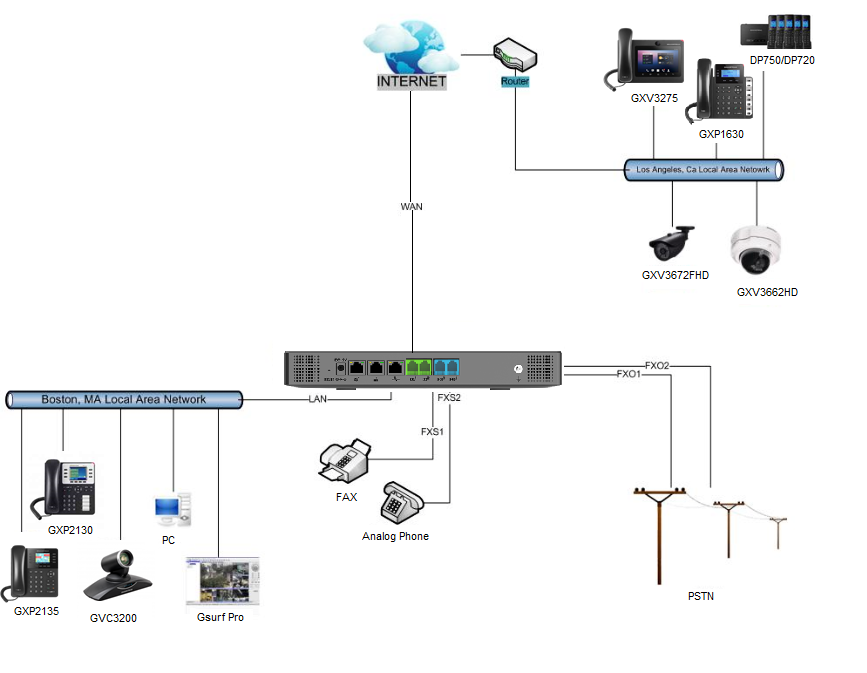
The image below shows the most typical setup where you have the UCM6XXX series WAN port connected to the Internet and the LAN side of the UCM6XXX series providing DHCP.
We will use this scenario to setup a Grandstream GXP2135 which will be connected to the LAN side of the UCM6xx series. There can also be a network switch connected to the LAN port of the UCM6xxx series so that there may be more than one device connected.
QUICK INSTALLATION
Connecting the UCM6XXX
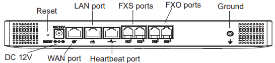
- Connect one end of an RJ-45 Ethernet cable into the WAN port of the UCM6301.
- Connect the other end of the Ethernet cable into the uplink port of an Ethernet switch/hub.
- Connect the 12V DC power adapter into the 12V DC power jack on the back of the UCM6301. Insert the main plug of the power adapter into a surge-protected power outlet.
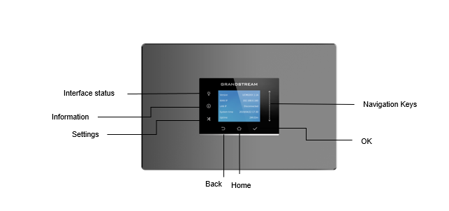
- Wait for the UCM6301 to boot up. The LCD in the front will show the device hardware information when the boot process is done.
- Once the UCM6301 is successfully connected to network, press the home button to display the IP address.
- (Optional) Connect PSTN lines from the wall jack to the FXO ports; connect analog lines (phone and Fax) to the FXS ports.
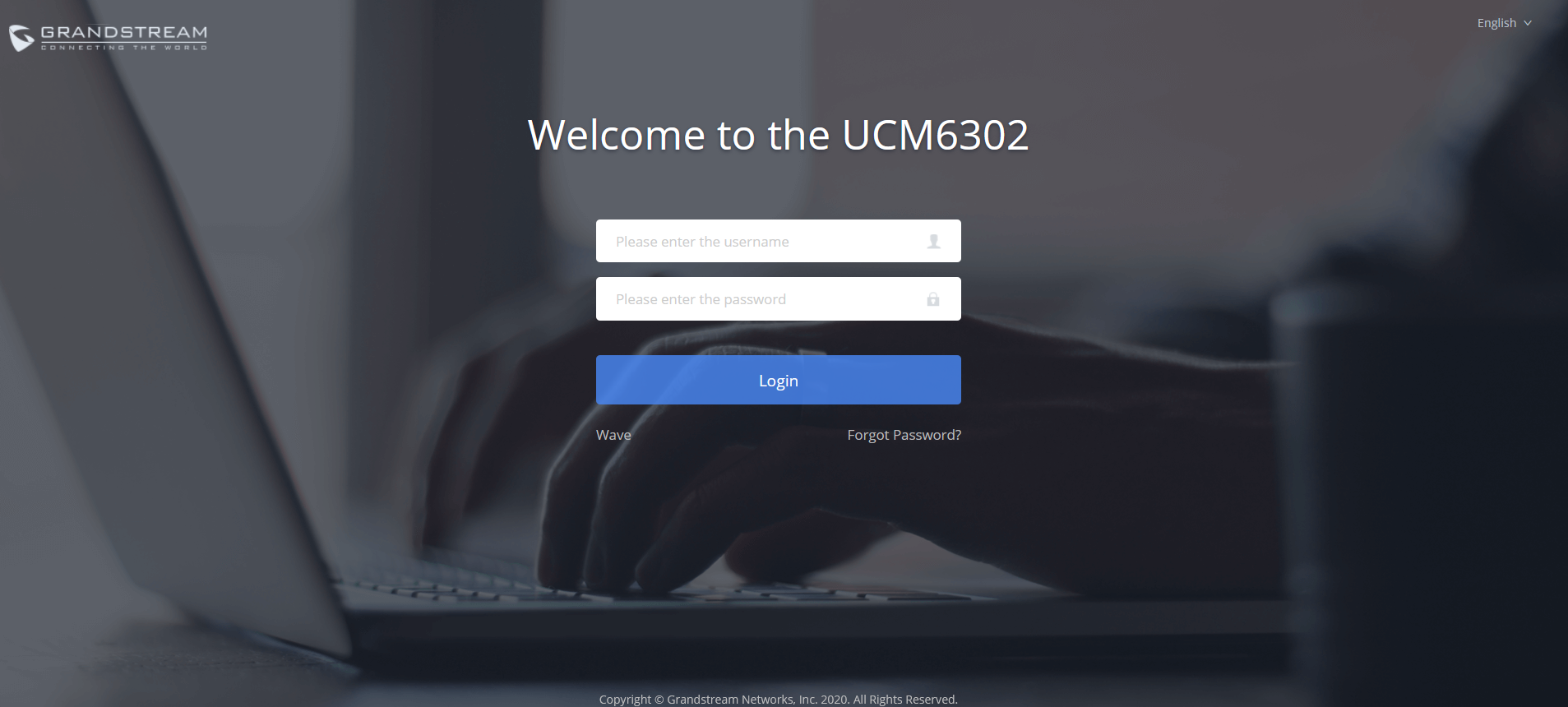
Access UCM6xxx series Web Interface
The UCM’s web server responds to HTTP/HTTPS GET/POST requests. Embedded HTML pages allow users to configure the device through a web browser such Microsoft IE (version 8+), Mozilla Firefox, Google Chrome, etc. To access the UCM’s web portal, follow the steps below:
- Make sure your computer is on the same network as the UCM.
- Make sure that the UCM’s IP address is displayed on its LCD.
- Enter the UCM’s IP address into a web browsers’ address bar. The login page should appear (please see the above image).
- Enter default administrator username “admin” and password can be found on the sticker at the back of the UCM.
CREATE USER EXTENSION
Configure Extension Range
First part of configuring the UCM62xx series should be about planning for expansion. Here are some questions to think about when setting up extension ranges:
- How many users are in the office?
- Will there be departments within the office?
- Is this office interconnecting with another office?
Once there’s a clear picture of how many users will be at each location, how departments are going to be segmented and what’s the expected growth of the company, a user can then configure the extension range. Navigate to PBX Settings 🡪 General Settings 🡪 Extension Preference.
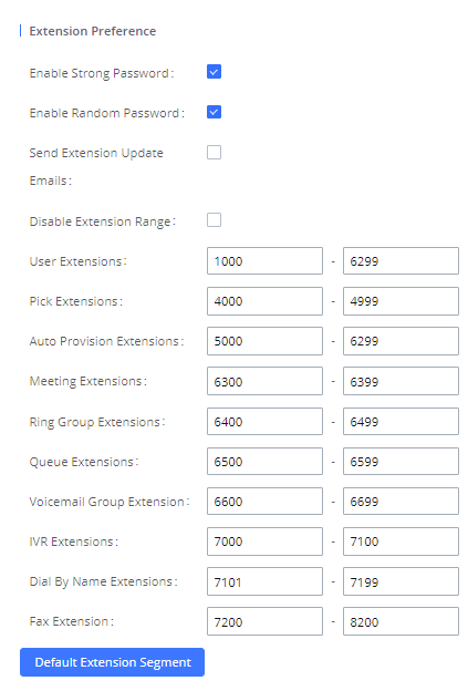
In the figure above, the user extension range is set with a starting extension of 1000 and ending at 6299. This allows up to 5299 extensions to assign to users. Users can configure any extension range as they desire. Here we’ve configured it to use four-digit extensions with a leading 1.
Click Save and then Apply Changes at the top so that our extension range will be ready for the next steps.
Batch & Single User Creation
So now that there are extension ranges configured, we can now begin creating users to prepare for the provisioning process. There are two methods of creating a user. One method would be creating a single user. The other method would be creating a batch of users.
Steps on Adding Single User
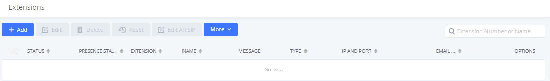
- Navigate to Extension / Trunk 🡪 Extensions. For first time setups users will see “No Data”.
- Click on “Add”
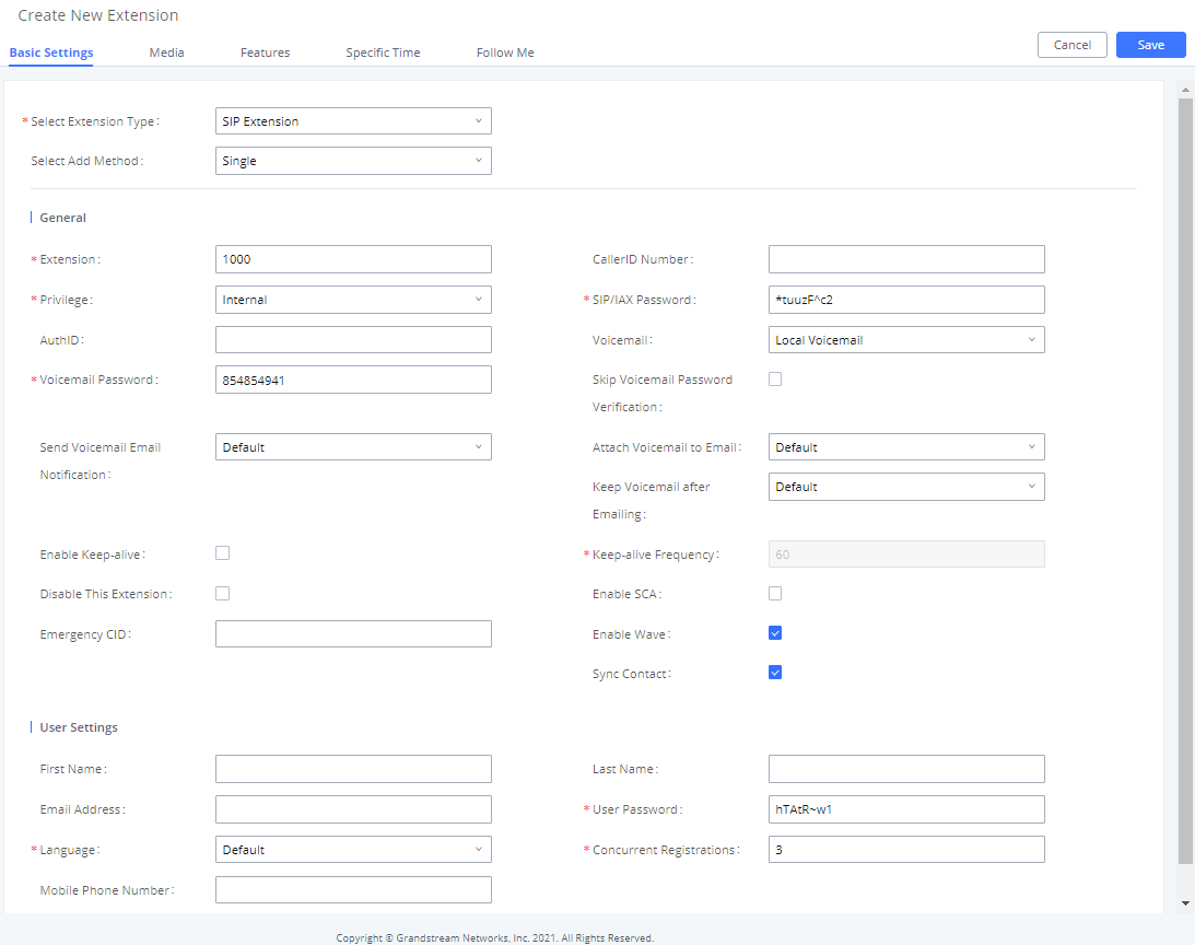
- Choose Create New SIP Extension.
- On the “Create New SIP Extension” screen, users can enter in quite a few options, but they are not required for this tutorial. Click “Save” at the bottom of the page.
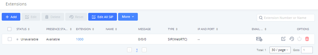
After clicking “Save” the Extensions page will display with the single SIP extension that was just created. Here the user has the ability to edit the extensions by clicking the
![]() at the right.
at the right.
Steps on Adding Batch of Users
- Navigate to Extension / Trunk 🡪 Extensions.
-
Click on “Add” button
 .
.
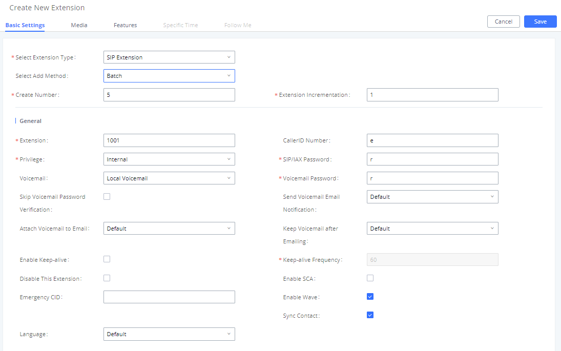
- Choose “Batch” under “Basic Settings” 🡪 “Select Add Method”.
- At the “Batch Add SIP Extensions” dialog, the user can specify the “Extension” and the number of extensions to generate by setting the “Create Number”.
In this tutorial we will have a starting extension of 1001 and have the UCM6XXX series generate 5 extensions with a password randomly generated. This would create extensions 1001, 1002, 1003, 1004 and 1005.
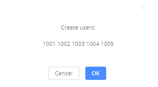
- Click “Save” button to have the UCM6XXX series generate the extensions.
- Next, a prompt will appear asking “Are you sure you want to create users: 1001, 1002, 1003, 1004 1005”. Click “OK”.
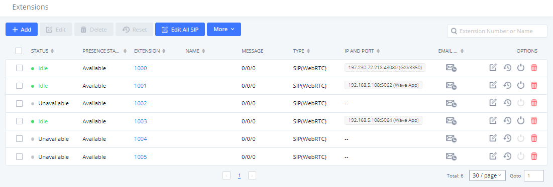
At this point the Extensions page should look similar to this:
For more details on Extension parameters please see thehttps://documentation.grandstream.com/knowledge-base/ucm630x-series-user-manual/
PROVISIONING & ZERO CONFIG
Grandstream SIP Devices can be configured via Web interface as well as via configuration file through TFTP/HTTP/HTTPS download. All Grandstream SIP devices support an XML format configuration file. The UCM6XXX provides a Plug and Play mechanism to auto-provision the Grandstream SIP devices in a zero configuration manner by generating XML config file and having the phone to download it. This allows users to finish the installation with ease and start using the SIP devices in a managed way.
To provision a phone, three steps are involved, i.e., discovery, assignment and provisioning. The UCM6XXX creates XML config file to the detected/assigned Grandstream device and accomplishes the following configurations on the device after the provisioning:
- A UCM6XXX extension will be assigned and registered on the phone.
- SIP-related network settings such as “NAT traversal” and “Use Random Port” are configured on the phone.
- Call settings such as “Dial Plan” and “Auto Answer”.
- LDAP client configurations will be set up automatically on the phone to use the default LDAP directory generated in the UCM6XXX LDAP server.
This section explains how zero config works on the UCM6XXX. The settings for this feature can be accessed via Web GUI 🡪 Other Features 🡪Zero Config.
When referring back to our typical scenario in the beginning of this tutorial, we know that there is a GXP2135 connected to the LAN side of the UCM62xx series. The UCM6XXX series LAN interface has DHCP enabled and has assigned the GXP2135 with an IP address. By default, the IP assigned would be within the 192.168.2.X range. When the UCM6XXX series offers an IP address to the phone it also offers DHCP Option 66, which provides the phone with a config server path that points to the UCM6XXX series. All of Grandstream VoIP devices have Option 66 turned on by default and this is how the GXP2135 was discovered by the UCM6XXX.
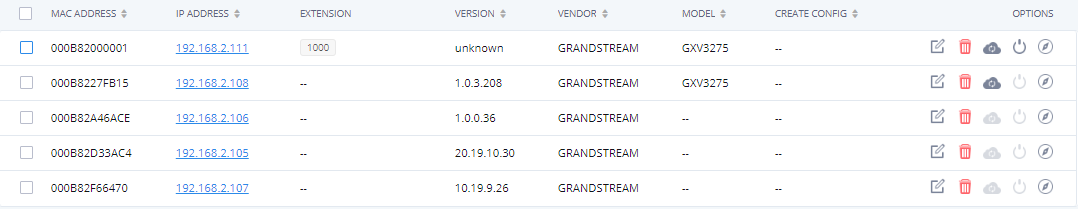
Upon being discovered, the GXP2135 will provide details about its MAC, IP Address, Version (Firmware), Vendor, Model, Connection Status and Create Config. By navigating to Other Features 🡪Zero Config, a user will be able to see the discovered device(s).
Extension Assignment
In the Auto Provision settings, users have the option to enable “Automatically Assign Extension”. If enabled, an extension will be created and assigned to the new device detected. This is a great feature if specific extension assignment isn’t required, but for our setup we’ll work on manually assigning an extension to a discovered device.
Navigate to Other Features 🡪Zero Config and click on the ![]() for the discovered device.
for the discovered device.
The next screen provides details of the device and also allows a user to assign an extension. Since our GXP2135 is a 4-line phone, the UCM6XXX series gives us the option to assign 4 extensions to the phone.
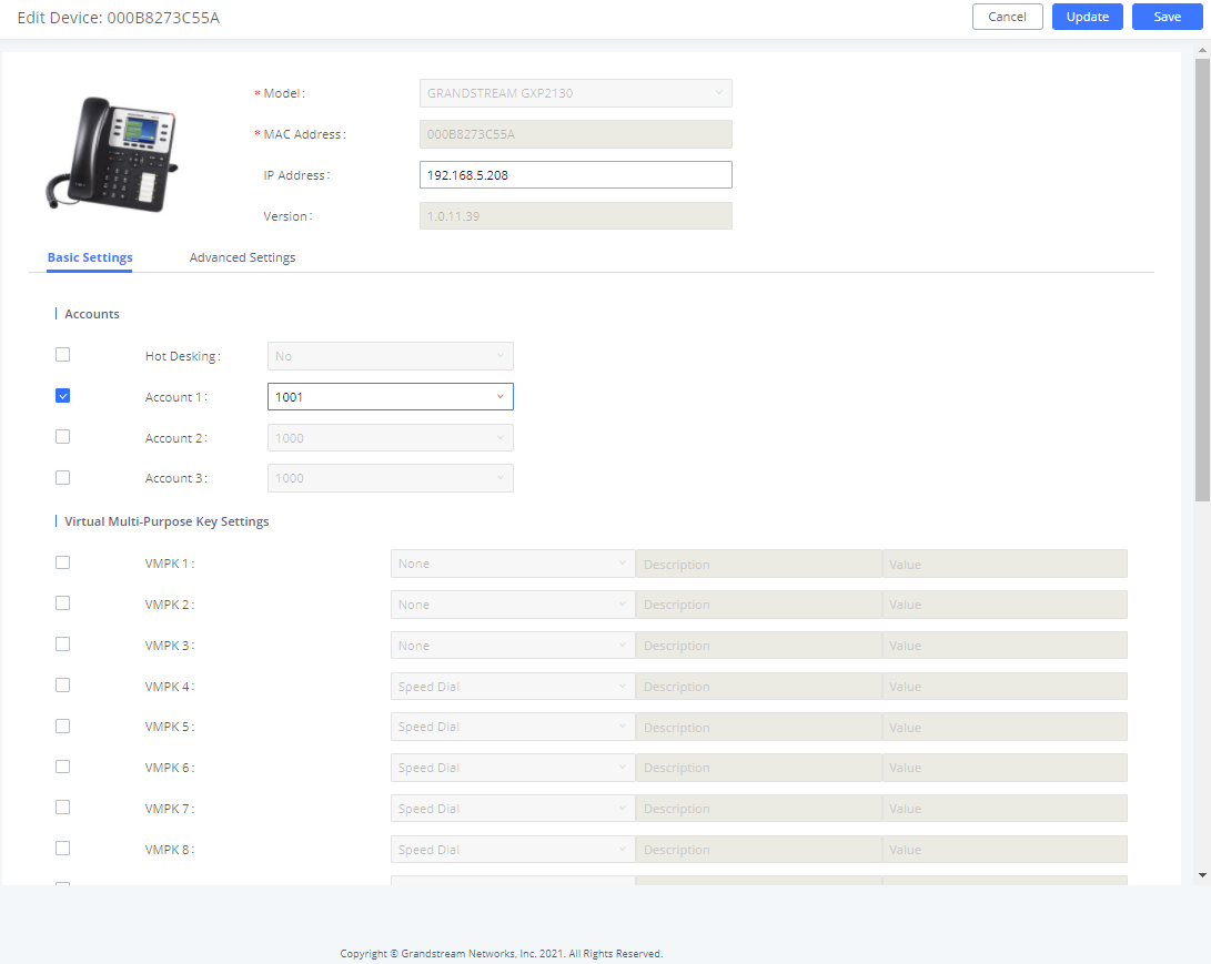
Check Account 1 and select the desired extension, then click “Save”. Now the Zero Config page displays the device with an extension assigned to it on Account 1.

After assigning an extension, the phone may be rebooted in order to pick up the configuration file from the UCM6XXX series. During this process, the phone will boot up, request for config file, download the config file, then reboot once more in order to apply the changes.
After the phone is completely booted, navigate to Extension / Trunk 🡪 Extensions page to see the extension status. The SIP status will show a green circle for a successful registration.

CONFERENCE BRIDGE
The UCM6xxx supports conference bridge allowing multiple bridges used at the same time:
- UCM6202/6204 supports up to 3 conference rooms allowing up to 25 simultaneous PSTN or IP
participants.
- UCM6208 supports up to 6 conference rooms allowing up to 32 simultaneous PSTN or IP
participants.
- The UCM6510 supports Conference rooms allowing 64 participants with up to 8 bridged rooms at
the same time.
- The UCM6301 supports up to 4 Video Conference rooms and up to 20 parties with 1080p.
- The UCM6302 supports up to 6 Video Conference rooms and up to 30 parties with 1080p.
- The UCM6304 supports up to 8 Video Conference rooms and up to 60 parties with 1080p.
- The UCM6308 supports up to 10 Video Conference rooms and up to 80 parties with 1080p.
- UCM6300A supports up to 3 meeting rooms and up to 50 parties
- UCM6302A supports up to 5 meeting rooms and up to 75 parties.
- UCM6304A supports up to 7 meeting rooms and up to 120 parties
- UCM6308A supports up to 9 meeting rooms and up to 150 parties
The conference bridge configurations can be accessed under Web GUI🡪 Call Features 🡪 Conference for the UCM62xx and UCM6510, from Call Features 🡪 Multimedia Meeting for the UCM630x series and from Call Features 🡪 Meeting Room for the UCM630xA.
Users could create, edit, view, invite, manage the participants and delete conference bridges and meeting rooms. The conference bridge status and conference call recordings (if recording is enabled) will be displayed in this web page as well.
How to Set up a Conference Bridge (UCM62xx/UCM6510)
- Click on “Add”.
- On “Create New Meeting Room” Page ,
- At the “Create New Conference” screen, the Extension is automatically populated since the extension range is in effect. Users can assign another number that is within the Conference Extension range.
- Enter a numeric password for an admin as well as the regular user password. In this example, the user enters 511511 as the user password and 510510 as the host password.
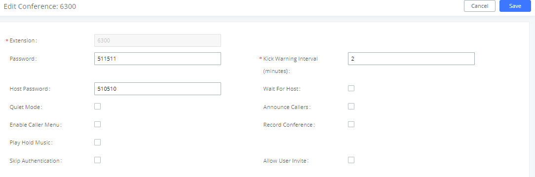
- Click “Save” at the bottom then “Apply Changes” at the top.
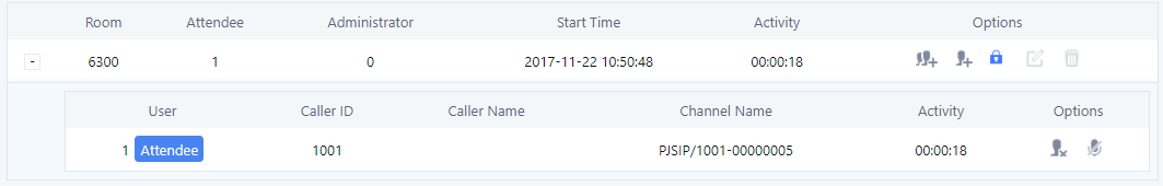
We should now have a conference room created and the status page will display the following:

With the phone that is registered to the UCM6XXX series, dial the conference room extension. For this example, we will dial 6300. The user will hear a prompt for the conference password. Depending on the user, the regular password or admin password can be entered.
During a conference call, the admin can log in to the UCM6XXX series and view the conference room status. This provides the admin with details on which conference room is active, who the participants are and the conference call’s current duration.
Besides status information, the admin has several conference managements tools. By clicking the
![]() button,
button,
the admin can invite other users to the conference. Clicking
![]() will kick the selected user from the conference. When clicking
will kick the selected user from the conference. When clicking
![]() or
or
![]() button the admin will mute/unmute the specific user.
button the admin will mute/unmute the specific user.
For more options and features for the conference room, please see the https://documentation.grandstream.com/knowledge-base/ucm630x-series-user-manual/
How to set up a Meeting Room in the UCM630x
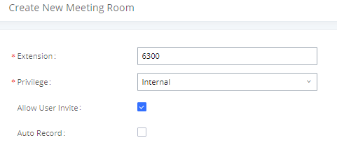
1. Under Call Features 🡪 Multimedia Meeting 🡪 Room 🡪 Click on “Add”.
2. Enter the Room’s extension number and specify the Privilege for the permission level for outgoing calls.
3. Users can choose to enable Allow user Invite option and Auto Record.
The conference room status and conference call recording (if recording function is enabled) will be displayed on the page. The meeting rooms in the list include public meeting rooms and random meeting rooms. For temporary meeting room administrators, only the “batch kicking people” function is supported. The temporary meeting room has no meeting password and host code. The member who initiates the group meeting is the host, and ordinary members have the right to invite.
For more options and features for the conference room, please see the UCM630x/A series User Manual.
How to Set up a Meeting Room in the UCM630xA
1. Under Call Features 🡪 Meeting 🡪 Room 🡪 Click on “Add”.
2. Enter the Room’s extension number and specify the Privilege for the permission level for outgoing calls.
3. Users can choose to enable Allow user Invite option and Auto Record.

The conference room status and conference call recording (if recording function is enabled) will be displayed on the page. The meeting rooms in the list include public meeting rooms and random meeting rooms. For temporary meeting room administrators, only the “batch kicking people” function is supported. The temporary meeting room has no meeting password and host code. The member who initiates the group meeting is the host, and ordinary members have the right to invite.
For more options and features for the conference room, please see the UCM630xA series User Manual.
IVR (INTERACTIVE VOICE RESPONSE)
Configure IVR
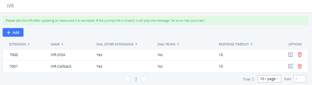
IVR configurations can be accessed under the UCM630X Web GUI🡪Call Features🡪IVR. Users could create, edit, view, and delete an IVR.
- Click on “Add” to add a new IVR.
-
Click on
 to edit the IVR configuration.
-
Click on
 to delete the IVR.
Create New IVR
- Click on “Add”.
- Enter a Name for the IVR. This is used for referencing purposes. In this example the user will create “OfficeHours2”.
- “Extension” is populated automatically by the extension range that was created in the beginning of the tutorial. A user may choose another IVR extension within the range if desired.
- Enable “Dial Other Extensions” to allow callers who reach the IVR to dial a direct internal extension without having to go through voice prompts.
- “Welcome Prompt” is the recording that will be played when a caller reaches the IVR. Users can click on the “Prompt” link next to the dropdown box to configure a welcome prompt.
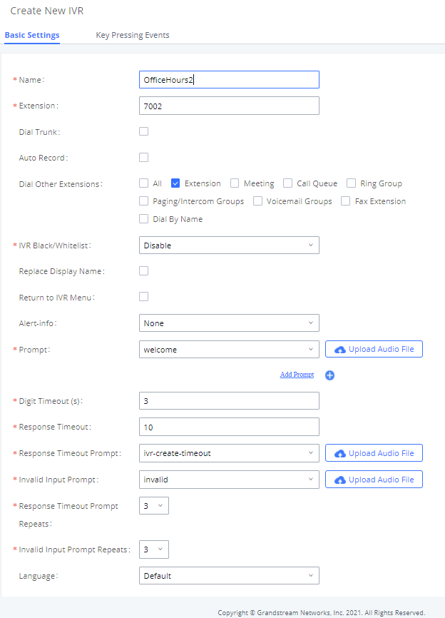
- The next section on configuring an IVR would be the Key Pressing Events. Users can direct calls based on a caller selection. For example, a caller reaches the IVR and the Welcome Prompt plays, “Thank you for calling Grandstream Networks. For support, please dial 0. For Sales, please dial 1.”
Click on the drop down box for the first event, which is “Press 0” and select Extension. Another drop down box will appear and the user can then select an extension from the list. For this example, the user selects Extension 1000.
- For Key Pressing Event “Press 1” click on the drop down box and select Extension. User selects Extension 1001. Besides from Extension as a Key Pressing Event, the user can select Voicemail, Conference Room, Voicemail Group, IVR, Ring Group and many more.
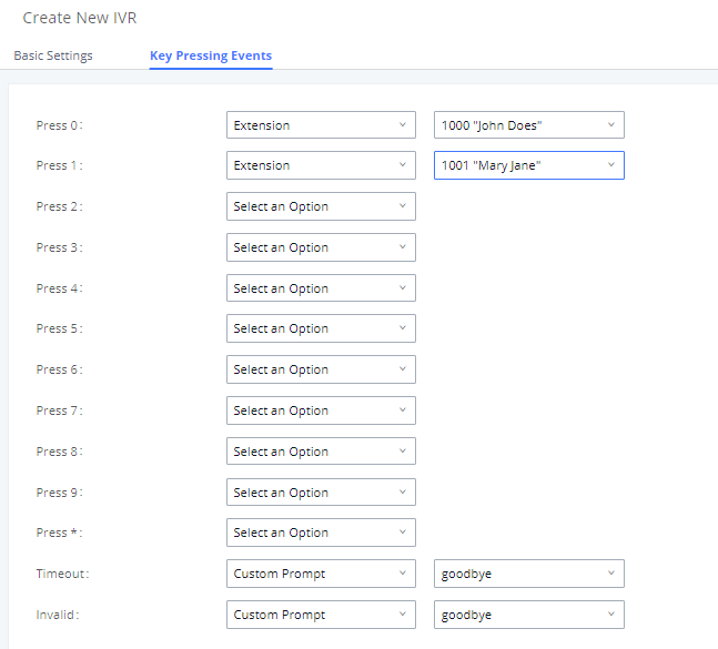
- Click “Save” button and then click on “Apply Changes” at the top.
To find out more options and parameter descriptions in regard to the IVR, please refer to the https://documentation.grandstream.com/knowledge-base/ucm630x-series-user-manual/
TRUNKS
Analog Trunks
Go to Web GUI 🡪 Extension / Trunk 🡪 Analog Trunks to add and edit analog trunks.
- Click on “Create New Analog Trunk” to add a new analog trunk.
-
Click on
 to edit the analog trunk.
-
Click on
 to delete the analog trunk.
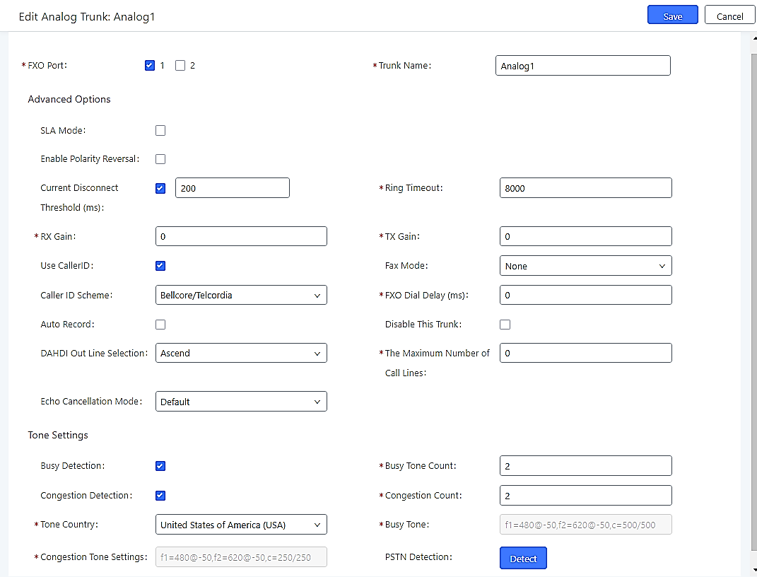
The UCM62xx series has built in FXO ports which allows it to pull in PSTN lines and provide analog trunk service. For this example, we will configure an analog line that is connected to FXO1.
Set up Analog Trunk
- Click on “Add”.
- Select the FXO ports used.
- Trunk Name is set to “Analog1”.
- “Caller ID Scheme” is set for “Bellcore/Telcordia”. Depending on the provider, users can select other schemes.
- “Tone Country” is set to “United States of America (USA)” since this tutorial is set up in the North American region. Users can click the dropdown box to select an option more suited for their region.
- Click “Save” and then click on “Apply Changes” at the top.
VoIP Trunks
VoIP trunks can be configured under Web GUI 🡪 Extension / Trunk ->VoIP Trunks. Once created, the VoIP trunks will be listed with Provider Name, Type, Hostname/IP, Username and Options to edit/detect the trunk.
- Click on “Create New SIP Trunk” or “Create New IAX Trunk” to add a new VoIP trunk.
-
Click on
to configure detailed parameters for the VoIP trunk.
-
Click on
 to configure Direct Outward Dialing (DOD) for the VoIP Trunk.
-
Click on
 to start LDAP Sync.
-
Click on
to delete the VoIP trunk.
There are 4 different type of VoIP trunks that can be configured. The types are Peered/Registered SIP trunk or Peered/Registered IAX trunk. This tutorial will demonstrate how to configure a SIP Registered Trunk.
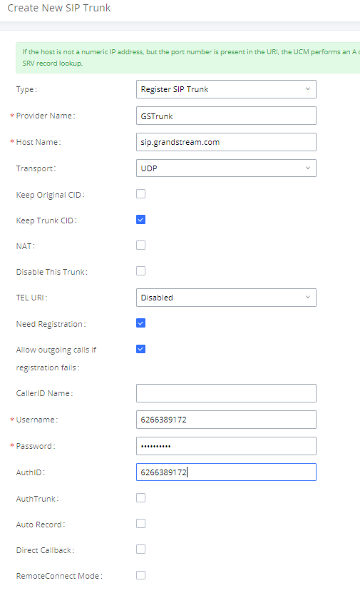
Set up VoIP Trunk
- Click on “Add” to “Create New SIP Trunk”.
- Click the dropdown box for Type and select “Register SIP Trunk”.
- Enter a name for “Provider Name” e.g., GSTrunk.
- Configure the IP address or URL of the VoIP providers server as the “Host Name” e.g., sip.grandstream.com.
- Input the username to authenticate with the VoIP provider as the “Username” e.g, 6266389172.
- Enter password for username to authenticate with VoIP provider server.
- Enter the AuthID. This is the SIP service subscriber’s ID used for authentication. If not configured, the CallerID will be used for authentication.
- Enter an outbound proxy if the provider requires one.
- Click “Save” and then “Apply Changes” at the top
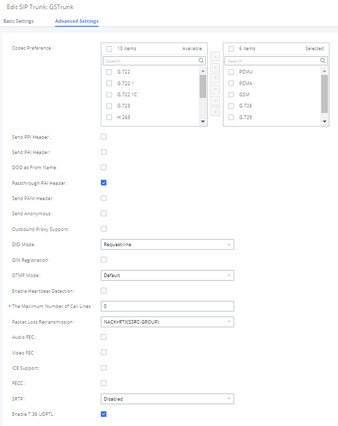
After creating the SIP trunk, users can click the
![]() on the right of the VoIP trunk for more configuration options.
on the right of the VoIP trunk for more configuration options.
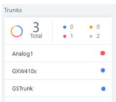
To verify if the SIP trunk is registered, the user may navigate to Web UI 🡪 System Status 🡪 Dashboard.
CALL ROUTES
Outbound Routes
In the UCM6XXX, an outgoing calling rule pairs an extension pattern with a trunk used to dial the pattern. This allows different patterns to be dialed through different trunks (e.g., “Local” 7-digit dials through a FXO while “Long distance” 10-digit dials through a low-cost SIP trunk). Users can also set up a failover trunk to be used when the primary trunk fails.
Go to Web GUI 🡪 Extension / Trunk 🡪Outbound Routes to add and edit outbound rules.
- Click on “Create New Outbound Rule” to add a new outbound route.
-
Click on
 to edit the outbound route.
-
Click on
 to delete the outbound route.
-
Click on
 to move the outbound route up/down to arrange the priority of the outbound rule. The outbound rule listed on the top has higher priority. When the dialing pattern matches two or more outbound rules (for example, the same pattern is configured for 2 different trunks; or dialing out 1000 matches pattern 1xxx for trunk 1 and pattern 100x for trunk 2), the one listed on the top will be used.
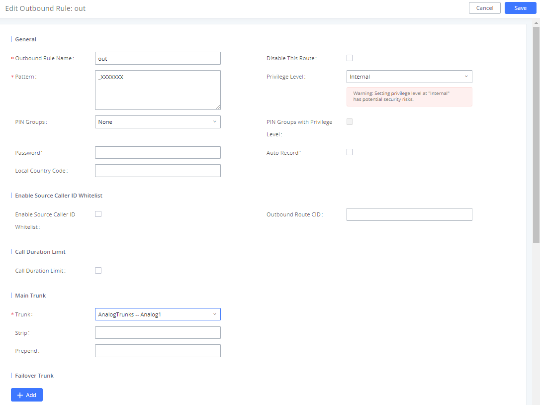
How to Configure an Outbound Route
- Click “Create New Outbound Rule”.
- Configure the name of the Calling Rule. For example, ‘Local’, ‘LongDistance’ and etc.
- Create a dial Pattern. For 7 digit dialing (Local) the pattern will look like this: XXXXXXX.
This means that any 7 digits will use this route. For 10 digit dialing the pattern would look like this: NXXNXXXXXX. If an ‘1’ is required before dialing out, the dial pattern can be configured in this manner: 1NXXNXXXXXX.
In this example, the dial pattern is going to be created for local 7 digit dialing so the pattern is XXXXXXX
- Next, set a “Privilege Level”. There are 4 Privilege Levels; Internal, Local, National, International. Internal is the lowest level of security whereas international is the highest level of security.
The way that Privilege Levels are used could be thought of as door locks. Extensions are granted with “Permissions” that can be seen as keys. If an Extension is configured with an Internal permission, it CANNOT access an outbound route with a Privilege level of Local, National and International. A user configured with National permission can access routes that have a Privilege Level of Internal, Local, National, but not International.
- The pattern that was configured is a 7-digit dialing pattern. For “Use Trunk” select the Analog Trunk or select the desired trunk for this particular dial pattern. For long distance calls, it may be cost effective to route the calls to SIP trunk versus going through a local PSTN line.
- Click “Save” and then click on “Apply Changes” at the top.
Inbound Routes
In the UCM6XXX, an incoming calling rule allows for various inbound destinations. Users can route inbound calls by DID, to Extension, Voicemail, Conference Room, Queue, Ring Group, Page, Voicemail Group, FAX, DISA or IVR. These inbound routes can also be triggered based on a time condition as well.
Inbound routes can be configured via Web GUI 🡪 Extension / Trunk ->Inbound Routes.
- Click on “Create New Inbound Rule” to add a new inbound route.
- Click on “DID Features” to configure DID features for the inbound route.
- Click on “Blacklist” to configure blacklist for all inbound routes.
-
Click on
to edit the inbound route.
-
Click on
to delete the inbound route.
This section of the tutorial will provide instructions on how to setup an inbound route for a Registered SIP Trunk. Inbound calls into this SIP trunk will have a default destination as well as a time conditioned destination.
Set up Inbound Route
- Click on “Create New Inbound Rule”.
- For “Trunks” select the SIP trunk that has been configured. (e.g. GSTrunk).
- The DID pattern can be composed of two parts, divided by a ‘/’ character. The first part is used to specify the dialed number and the second part is used to specify the caller ID, which is optional. If caller ID section is entered it means only the extension with the specific caller ID is allowed to call into this trunk.
- Click the dropdown box for “Default Destination” and select IVR. Then select the IVR extension.
- Next, click on “Click to add Time Condition”.
- Enter a “Start Time” of 8am, “End Time” of 18pm.
- Next select By Week for “Date” and select Monday-Friday.
- For “Destination” select Extension and choose an extension number.
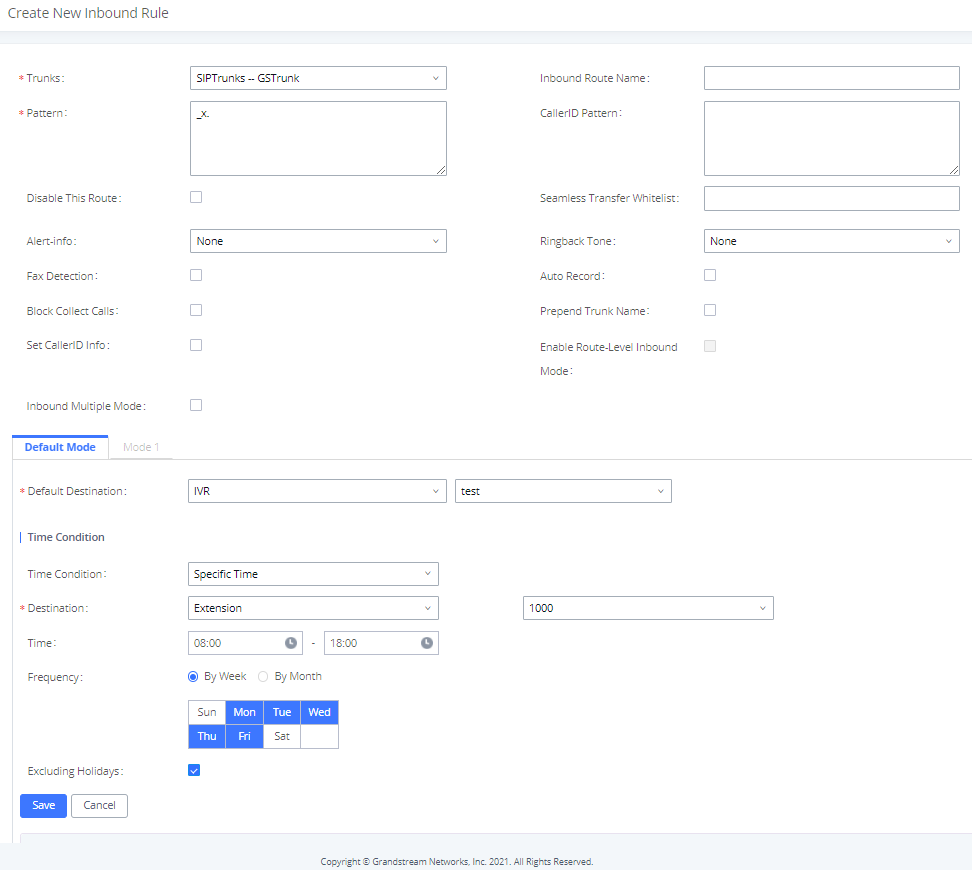
When a call is received on this SIP trunk during the hours of 8:30am to 11:30pm it will be routed to extension 1000. All calls outside of this condition will be routed to the IVR.