


INTRODUCTION
The 1+N media cluster feature allows clustering multiple devices from the UCM630x and GCC602x series to expand the number of concurrent calls and meeting participants.
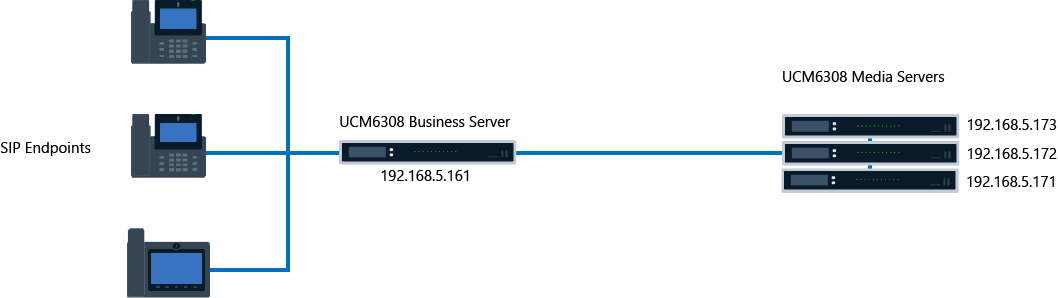
The deployment architecture of this feature consists of one main business server that handles signaling, and at least one other server handling the media traffic. Please see the example for the UCM630x series below.
CONFIGURATION STEPS
The configuration of the cluster feature consists of two main parts, one part will be about the configuration of the business server, and the other part will be about the configuration of the media server(s).
Business Server
Setting a Static IP address
To ensure that the connection isn’t lost to the business server, the user must configure a static IP on the business server.
- For UCM630x devices:
A static IP can be configured directly in the web UI or reserved on the DHCP server.
- Access the web UI, navigate to System Settings → Network Settings, and then set a static IP on the network interface which is connected to the network where the media servers are hosted.

- Click “Save” to save the configuration.
- For GCC602x devices:
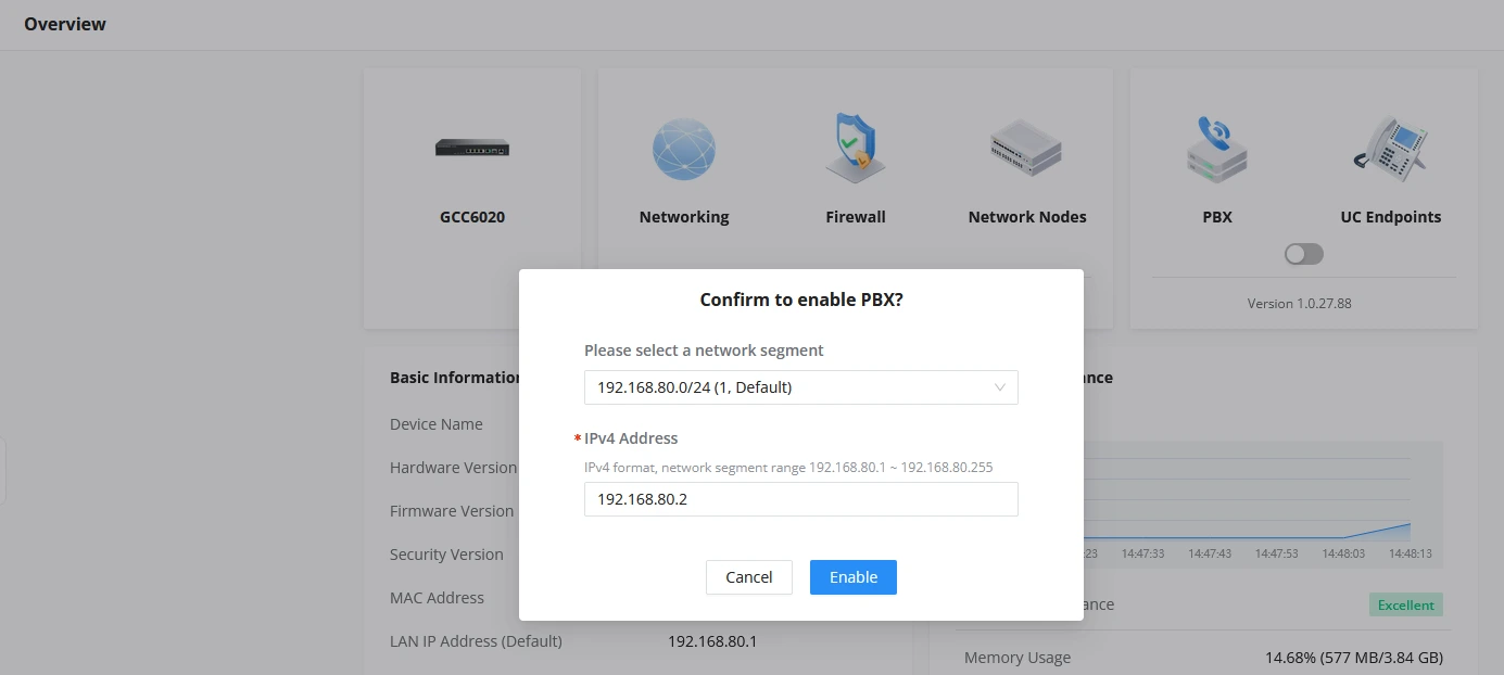
A static IP can only be set when enabling the PBX module. After the PBX module is enabled, the IP cannot be modified directly. To change it, the PBX module must be disabled and re-enabled. The previous configuration remains intact after re-enabling.
Configuring the Cluster Settings
To configure the UCM/GCC device as the Business Server, please follow the steps below:
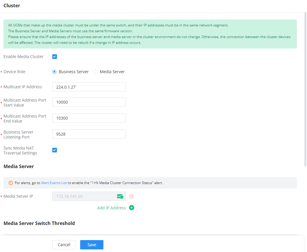
- Navigate to System Settings → Cluster, then tick the option Enable Media Cluster.
- Choose “Business Server” as the Device Role.
- Choose the Multicast Network Port. This depends on the networking settings of the device (Route mode or Dual mode).
- Enter a Multicast IP address that will be used to send multicast traffic. Please ensure the IP address is within the allowed multicast range (224.0.1.0 – 238.255.255.255).
- Enter a port range start value and end value in the corresponding fields. The range must be between 1024 – 65535.
- Enter the Business Server Listening Port number. This must also be within 1024 – 65535.
- Enter the Media Server addresses. These can be added in advance and later assigned to the media server(s).
- Once all settings are entered, click “Save” to save the configuration.
Parameter | Description |
Enable Media Cluster | Enable Media Cluster feature. |
Device Role | Configure the device role.
|
Multicast IP Address | The allowed multicast IP address range is 224.0.1.0 – 238.255.255.255 |
Multicast Address Port Start Value | Enter the multicast address port start value. The port number value can be within the range 1024 – 65535. Note: The multicast address port start value must be lower or equal to the multicast address port end value. |
Multicast Address Port End Value | Enter the multicast address port end value. The port number value can be within the range 1024 – 65535. Note: The multicast address port end value must be greater or equal to the multicast address port start value. |
Business Server Listening Port | The port on which the business server listens and receives information reported by the media server. The value of the listening port value can be within 1024 – 65535. |
Sync Media NAT Traversal Settings | If enabled, all media servers in the cluster will use the same Media NAT Traversal settings as the business server. If disabled, each server will need to be configured individually. |
Media Server | |
Media Server Settings | Enter the IP address of the media server.
The statuses of the media servers are indicated using three colors:
|
Media Server Switch Threshold | |
Memory Usage Threshold (%) | When the memory usage of this media server is exceeded, media services will be assumed by another media server in the cluster with the lowest usage at the time. |
CPU Usage Call Control Threshold (%) | When the CPU usage of this media server is exceeded, media services will be asssumed by another media server in the cluster with the lowest usage at the time. |
Media Server Usage Threshold | |
Memory Usage Threshold (%) | When this server’s memory usage exceeds the specified threshold, service from this server will be temporarily paused. |
CPU Usage Call Control Threshold (%) | When this server’s CPU usage exceeds the specified threshold, service from this server will be temporarily paused. |
Disk Available Space (MB) | When the percentage of available space in the device’s disk data partition falls below the set value, this server will not be used until the amount of available space is above the threshold again. |
Media Server
Setting static IP address
Similar to the business server, we also need to set the static IP address for the media server to avoid losing the connection to it.
- For UCM630x devices:
A static IP can be configured directly in the web UI or reserved on the DHCP server.
- Access the UCM’s web UI, navigate to System Settings → Network Settings, and then set a static IP on the network interface which is connected to the network where the business server is hosted.
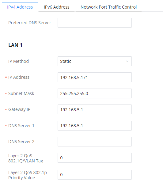
- Click “Save” to save the configuration.
- For GCC602x devices:
A static IP can only be set when enabling the PBX module. After the PBX module is enabled, the IP cannot be modified directly. To change it, the PBX module must be disabled and re-enabled. The previous configuration remains intact after re-enabling.
Configuring the Cluster Settings
To configure the GCC/UCM device as a media server, please follow the steps below:
- Please navigate to System Settings → Cluster
- Tick the option “Enable Media Cluster”
- Select “Media Server” as the Device Role
- Enter the IP address of the business server and the listening port configured on the Business server.
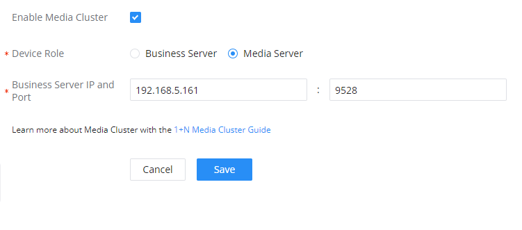
Enable Media Cluster | Enable Media Cluster feature. |
Device Role | Configure the device role. |
Business Server IP and Port | Enter the IP address of the business server with the listening port. If the business server is using HA Local Hot Standby, the Hot Standby Cluster IP address must be used. If the business server is using HA Remote Disaster Recovery, the primary UCM/GCC and secondary UCM/GCC must have their own respective cluster environments. |
- Then click “Save” to save the configuration.
CONSIDERATIONS
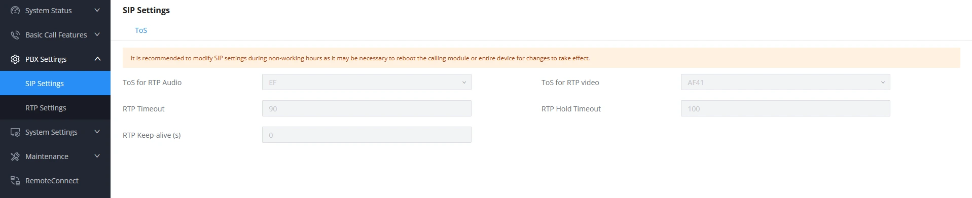
Some of the settings which are important for the normal operation of the cluster are synchronized automatically; meeting settings and RTP ToS settings are synchronized automatically. Meanwhile the NAT traversal settings such as TURN server address, STUN server address etc… are only sychronized if “Sync Media NAT Traversal Settings” option is enabled, please see [Business Server] section.
Meeting Settings
For media servers, all the configuration options on this page are greyed out to display the information configured on the business server.

SIP Settings
Please ensure that the following ToS SIP settings are identical across all the devices that are involved in the cluster. To access the configuration page please navigate to PBX Settings → SIP Settings → ToS
RTP Settings
If the Business Server is behind a NAT router and does not have a RemoteConnect plan, port forwarding must be configured on the router. Each media server, whether UCM or GCC, should use a unique port range for RTP and BFCP. For example:
- UCM1: 10000–20000
- UCM2: 20001–30000
- UCM3: 30001–40000
- GCC servers follow the same rule with their own ranges.
The same logic applies to BFCP. Port forwarding rules should map each range to the corresponding server’s IP address. If a TURN server is used, it can serve all media servers.
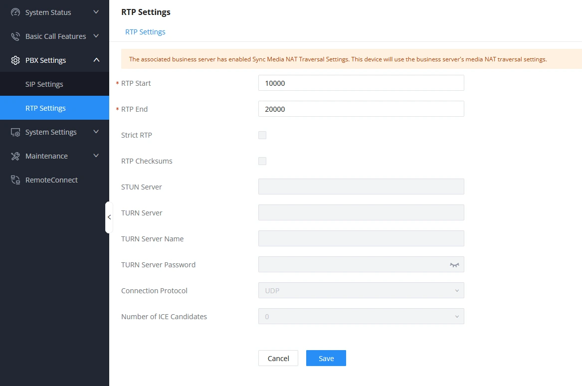
To access the configuration page of RTP Settings, please navigate to PBX Settings → RTP Settings
The following media NAT Traversal parameters will only be visible on the business server:

The remaining settings will be greyed out on the media server’s side. Only the configuration on the business server will be taken into consideration.
CLUSTER CAPABILITIES
The following table mentions the number of calls each business server is capable of processing and the additional calls that each media server will process based on the model of the device used.
UCM6304 | UCM6308 | GCC6020/GCC6021 | |
Business Server | |||
Max Concurrent Calls | 300 | 450 | Based on license |
Max Meeting Participants | 200 | 300 | Based on license × CPU Usage Call Control Threshold, max 75 |
Media Server | |||
Media Server Additional Concurrent Calls | 335 | 390 | Based on license |
Media Server Additional Meeting Participants | 250 | 300 | Based on license, max 75 |
- Example:
If a UCM6304 acts as the business server and has an additional UCM6304 and UCM6308 as media servers, the capacity would be as follows:
- Concurrent Calls = 300 (UCM6304 Business Server) + 335 (UCM6304 Media Server) + 390 (UCM6308 Media Server) = 1025
- Meeting Participants = 200 (UCM6304 Business Server) + 250 (UCM6304 Media Server) + 300 (UCM6308 Media Server) = 750
Additionally, CPU thresholds can be set on each media server to restrict the number of calls based on CPU usage. For example, if a 90% CPU threshold is set on both media servers, the capacity calculation would become:
- Concurrent Calls = 300 + ((335 + 390)*0.90) = 952
- Meeting Participants = 200 + ((250 + 300)*0.90) = 695
HIGH AVAILABILITY WITH THE CLUSTER
Local Hot-standby:
If the business server is configured with HA Local Hot-standby, then the media server must configure the Business Server IP field with the HA cluster IP address. In case of HA failover, the secondary unit will also be able to take advantage of the existing media cluster.
Remote Disaster Recovery:
Cluster configuration is not synced in Remote Disaster Recovery environments. Users can choose to expand the capacity of only one of the UCMs or both units. In the case of the latter, the primary and secondary units must configure their own separate cluster environments.
SUPPORTED DEVICES
Model | Firmware Version |
UCM6304 | 1.0.25.7+ |
UCM6308 | 1.0.25.7+ |
GCC6020 PBX | 1.0.27.89+ |
GCC6021 PBX | 1.0.27.89+ |