Hot-Swappable Power Supply Unit - Quick Installation Guide

  • Updated on April 16, 2024

Overview

Hot-swappable power supply unit provides seamless failover for internal power supply failures for network devices. It automatically senses if an internal power supply of a connected device fails and immediately supplies power to the device. The device then has continuous uptime without the need to reboot. It can be used in conjunction with Grandstream switches to achieve 1+1 redundant power backup and load current sharing. The CRPS920W provides PoE capability with a maximum output of 740W.

Introduction

Name

Adapter Model

Description

Supported Models

RPS-70W

U1A-H10070-DRB

Hot-swappable Power Supply Unit 70W

GWN7816

CRPS-920W

G1482-0920WNA

Hot-swappable Power Supply Unit 920W

GWN7816P

Introduction

Power supply unit comes with its own LED indicators, and its lighting logic is as follows:

Name

LED Indicator

Indicator Status

Description

RPS-70W

PWR

Off

Power off

Solid Green

Normal use

CRPS-920W

AC OK

Solid Green

AC input OK

Flashing Red

  • No AC input

  • AC loss

DC OK

Solid Green

DC output OK

Flashing Green

Only standby output on

Solid Red

DC output failure

LED Indicators

Notes:

  • For more switch models, please choose it according to the power supply requirements of the switch.
  • Compliance:

           (1) RPS-70W compliance: CCC, UL, CE, FCC, EAC, BSMI, UKCA, RCM

           (2) CRPS-920W compliance: UL, CB, CE, CCC, FCC, UKCA, CNCA, Ecology Declaration, KCC-Mark, TUV

  • When installing and removing the PSU, wear an anti-static wrist strap or gloves. it’s necessary to ensure that one end of the strap is grounded and the other end is in good contact with the wearer’s skin.
  • Before installation, ensure that the working voltage of the external power supply system, the voltage marked on the PSU, and the output voltage of the PSU are consistent with the required one.
  • Slowly insert the PSU during installation. If there is significant resistance or deviation in the insertion process, must unplug and reinsert it. Do not force installation otherwise, it will damage the connectors of the unit and the switch.
  • If the PSU is not used, a dummy panel must be installed in the slot, otherwise the heat dissipation of the switch will be affected.
  • The PSU supports hot swapping. It’s necessary to ensure that the main power supply of the switch is normal before swapping, otherwise it will cause the switch to power off and business will be interrupted.
  • Do not reach into the unit slot of the switch during the installation or removal.
  • Do not plug the PSU into a switch that is incompatible, which may lead to unknown risks.
  • Do not touch any exposed wire parts in the PSU.
  • Do not place the PSU in a damp place where the liquid may enter the interior of the switch.
  • Do not attempt to open the unit casing without permission.
  • Do not expose the RPS-70W to temperatures outside the range of -10°C to 50°C for operation and -40°C to 70°C for storage; do not expose the CRPS-920W to temperatures outside the range of -5°C to 55°C for operation and -40°C to 70°C for storage.
  • Do not expose the RPS-70W to environments outside of the following humidity range: 10%-90% RH (Non-condensing) for operation and 5%- 95% RH (Non-condensing) for storage; do not expose the CRPS-920W to environments outside of the following humidity range: 5%-90% RH (Noncondensing) for operation and 5%-95% RH (Non-condensing) for storage.

Package Content

Package Content

Install an Additional Power Supply Unit

Notes:

  • In models with more than one power supply bay, you can install an additional PSU.
  • Grandstream switch has a built-in power supply unit by default, which is already assembled at the factory. If purchased separately, please refer to the following steps for installation.
  • PSU Installation Sequence: Install the module → Connect the module to the AC cable → Connect the AC cable to the external power supply system; for disassembly, reverse the steps.

Step 1: Take the module from its packaging box. And confirm that the model of the PSU matches the requirements.

Step 2: Remove the dummy panel at the power slot on the back of the switch. Insert a flat screwdriver(prepared by yourself) into the protruding handle on the dummy panel and gently pull out the dummy panel outward along the slot guide. Please keep the removed dummy panel properly for future use.

Dummy panel removal

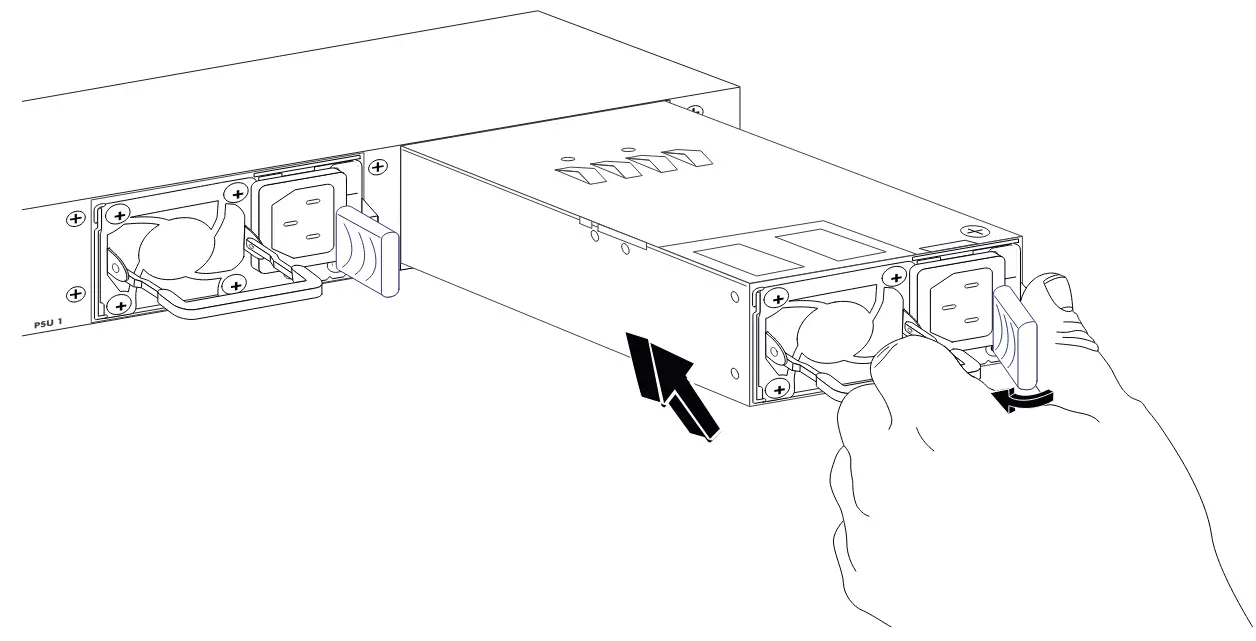
Step 3: Install the PSU secured by the latch. Hold the PSU handle with one hand and pull the bottom of the PSU with the other hand. Insert the PSU horizontally along the slot rail until it’s fully inserted into the slot and is flush with the switch. At this point, the PSU’s latch will automatically lock and you will hear the sound of the slot engaging.

Notes:

  • Confirm whether the direction of the PSU is correct. The text sticker on the PSU is facing upwards, indicating a positive direction.
  • When inserting the PSU, a slight inertia can be used to push it into the slot, ensuring good contact between the power terminal and the backplane socket.
  • To avoid damaging the PSU or the connectors in the switch slot, do not use excessive force when inserting the PSU. If the PSU encounters significant resistance or misalignment while being inserted, unplug the PSU first and then reinsert it.

PSU Installation

Step 4: Connect the AC cable to the PSU first, then connect it to the external power supply system. When the power is on, both the LEDs on the switch and on the PSU will light up with green indicating normal power and red indicating power failure. If the lights are off, please confirm whether the power cord is properly connected and whether the PSU is intact.

Replace the Power Supply Unit

Notes:

  • Before replacing the PSU, it’s necessary to ensure that the other power supply unit on the switch is in a power supply state during the replacement, otherwise unplugging the PSU will cause the switch to power off resulting in a business interruption.
  • The 2 power slots on the switch are 1+1 backup. When only one unit is working, it can ensure that the switch works normally. If multiple units need to be replaced, replace them one by one. During each replacement process, it’s necessary to ensure that the other unit is functioning properly (the LED light is green).

Step 1: If the switch functions with a single unit only, disconnect the power cord from the unit and let the switch power down; otherwise, do a hot swap directly.

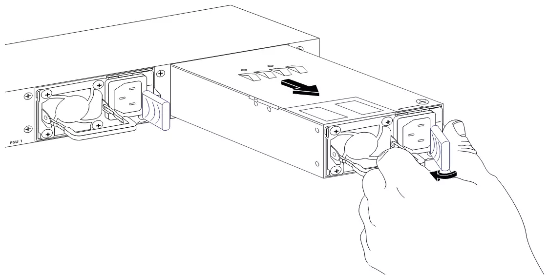
Step 2: Grasp the handle and use your thumb to move the release latch toward the handle side while pulling out the PSU outward. Use the other hand to drag the bottom of the PSU and slowly pull it all out of the switch.

PSU Replacement

Step 3: Install the backup unit into the slot, refer to the installation guide “Install an Additional Power Supply Unit”; if there is no need to install a new PSU, install the dummy panel to prevent dust from entering.

Subsequent processing: If the replaced unit does not operate properly, contact the equipment dealer or maintenance personnel for technical support.

Refer to online documents and FAQ for more detailed information:
https://www.grandstream.com/our-products


Was this article helpful?

Related Articles

Need Support?
Can’t find the answer you’re looking for? Don’t worry we’re here to help!
Contact Support