
Overview
The redundant power supply provides a stable switch running performance. It helps ensure uninterrupted operation and protection against device power supply failures by providing seamless failover for the switch. RPS-300W-B module provides PoE capability with a maximum output power of 240W.
RPS Introduction
RPS Name | Adapter Model | Description | Supported Models |
RPS-60W-B | UES65- 120500SPA2 | Redundant Power 12V5A 60W with Bracket | GWN7813 |
RPS-300W-B | PA-1301-66C3 | Redundant Power 54V5.56A 300W with Bracket | GWN7813P |
RPS Introduction
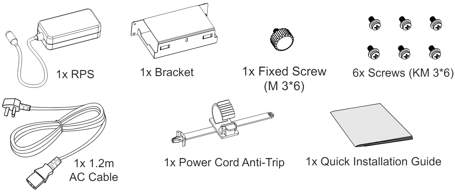
Package Content
Installation
GWN7813 switch will be taken as an example.
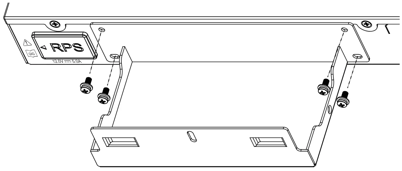
Step 1: Find the four screw holes next to RPS silicone plug on the back of the switch to ensure no obstructions.
Step 2: Fix the bracket base then align the four screw holes of the bracket base with the four screw holes on the back of the switch, and use KM3*6 screws to secure the base.
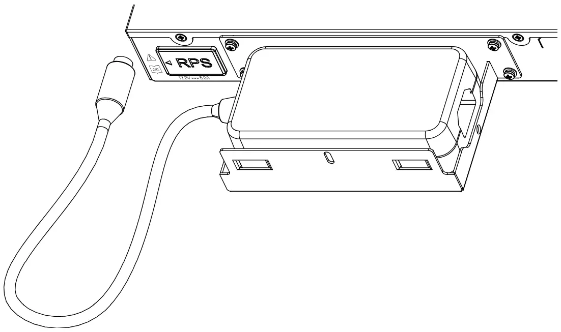
Step 3: Place the RPS horizontally into the bracket. Please ensure that the power cord is located on the side of the RPS silicone plug.
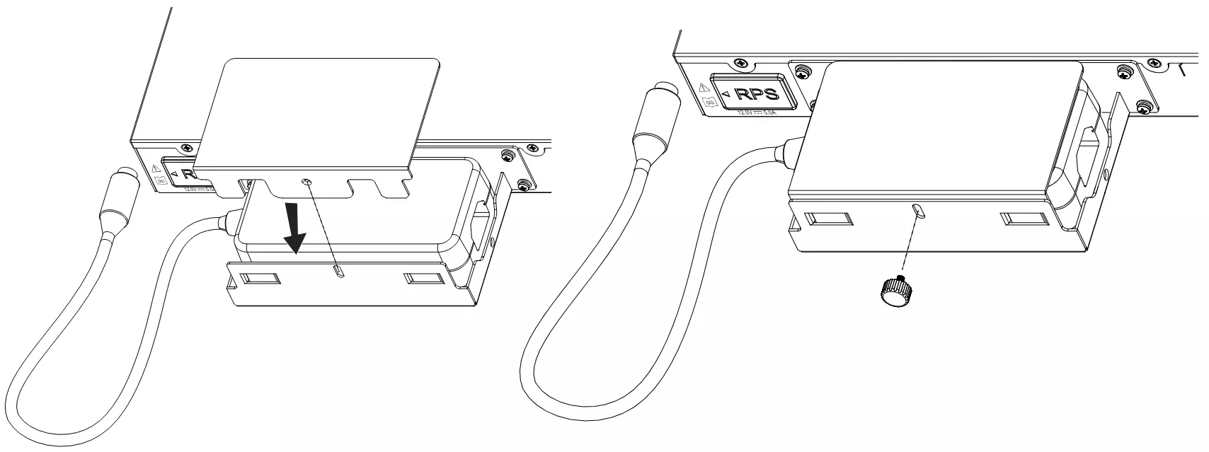
Step 4: Lower the bracket cover and ensure that the screw holes are aligned. Then, use the fixed screw (M3*6) to lock the RPS inside the bracket.
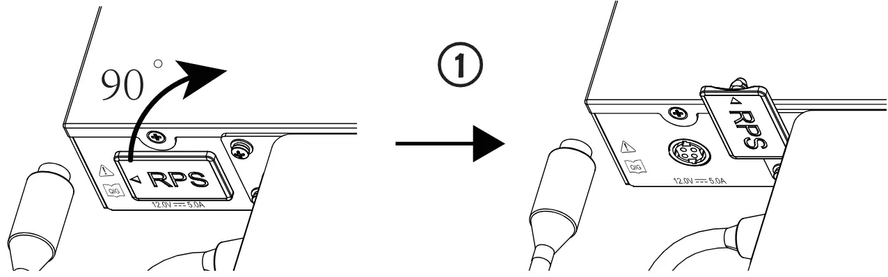
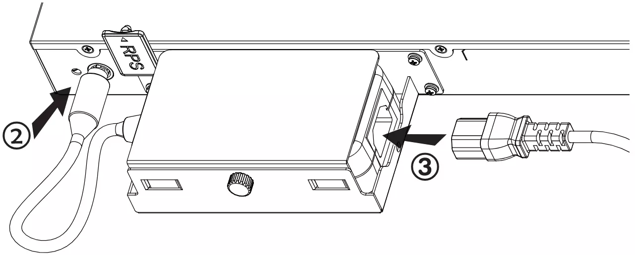
Step 5: Lift the RPS silicone plug from the arrow side and rotate it 90° clockwise to see the power hole, next connect the RPS to the switch, then connect the AC power cord to the RPS, finally complete the connection between the power cord and the power supply system.
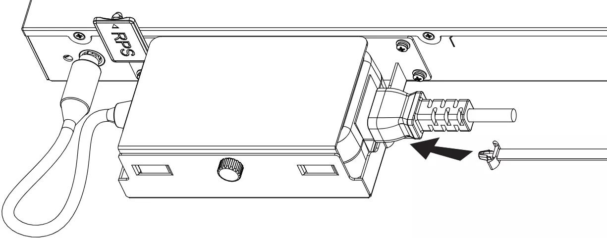
Step 6: To prevent accidental disconnection of the RPS, it’s recommended to use a power cord anti-trip for installation. Place the smooth side of the fixed strap towards the power cord and connect it to the anti-trap hole below the power cord.
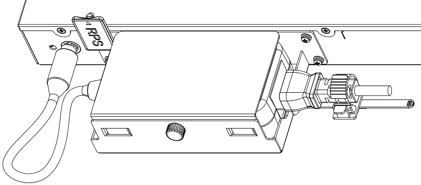
Step 7: Slide the protective rope over the fixed strap until the end of the power cord, then smoothly wrap the strap around the power cord and lock it tightly.
Refer to online documents and FAQ for more detailed information:
https://www.grandstream.com/our-products