


PRODUCT OVERVIEW
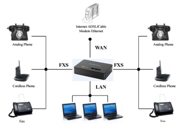
The HT81x V2 analog telephone adapters (ATA) allow users to create a high-quality and manageable IP telephony solution for residential and office environments. Their ultra-compact size, voice quality, advanced VoIP functionality, security protection, and auto provisioning options enable users to take advantage of VoIP on analog phones and allow service providers to offer high-quality IP service. The HT81x V2 are ideal ATAs for individual use and large-scale commercial IP voice deployments since it will enable small and medium businesses to create integrated IP and PSTN telephony systems that efficiently manage communication costs. HT81x V2’s inclusion of an integrated NAT router and dual 10/100/1000Mbps Ethernet WAN and LAN ports enables a shared broadband connection between multiple Ethernet devices and the extension of VoIP services to analog phones.
Feature Highlights
The following table contains the major features of the HT81x V2:
 HT812 V2  HT814 V2  HT818 V2 |
|
HT81x V2 Features at a Glance
HT81x V2 Technical Specifications
The following table resumes all the technical specifications including the protocols/standards supported, voice codecs, telephony features, languages, and upgrade/provisioning settings for the HT81x V2.
Interfaces | |
Telephone Interfaces | Two (2) RJ11 FXS ports for HT812 V2. Four (4) RJ11 FXS sports for HT814 V2. Eight (8) RJ11 FXS ports for HT818 V2. |
Network Interface | Two (2) 10/100/1000 Mbps Ethernet port (RJ45). |
LED Indicators | POWER, LAN, WAN, PHONE1, PHONE2 for HT812 V2. POWER, LAN, WAN, PHONE1, PHONE2, PHONE3, PHONE4 for HT814 V2. POWER, NET1, NET2, PHONE1, PHONE2, PHONE3, PHONE4, PHONE 5, PHONE 6, PHONE 7 and PHONE 8 for HT818 V2. |
Factory Reset Button | Yes. |
Voice, Fax, Modem | |
Telephony Features | Caller ID display or block, call waiting, flash, blind or attended transfer, forward, hold, do not disturb, 3-way conference. |
Voice Codecs | G.711 with Annex I (PLC) and Annex II (VAD/CNG), G.722, G.723.1, G.729A/B, G.726-32, iLBC, OPUS, dynamic jitter buffer, advanced line echo cancellation |
Fax over IP | T.38 compliant Group 3 Fax Relay up to 14.4kpbs and auto-switch to G.711 for Fax Pass-through. |
Short/Long Haul Ring Load | For HT812 V2: 3 REN, up to 1km on 24AWG line. For HT814 V2 and HT818 V2: 2 REN, up to 1km on 24AWG line. |
Caller ID | Bellcore Type 1 & 2, ETSI, BT, NTT, and DTMF-based CID. |
Dial Methods | DTMF, Pulse |
Disconnect Methods | Busy Tone, Polarity Reversal/Wink, Loop Current. |
Signaling | |
Network Protocols | TCP/IP/UDP, RTP/RTCP (RFC1889, 1890), HTTP/HTTPS, ARP/RARP, ICMP, DNS, DHCP, NTP, TFTP, SSH, Telnet, STUN (RFC3489, 5389), SIP (RFC3261), SIP over TCP/TLS, SRTP, SNMP, TR-069, IMS/3GPP, IPoE |
QoS | Layer 2 (802.1Q VLAN, SIP/RTP 802.1p) and Layer 3 (ToS, Diffserv, MPLS), Traffic Shaping |
DTMF Methods | In-audio, RFC2833 and/or SIP INFO. |
Provisioning and Control | HTTP, HTTPS, FTP, FTPS, SSH, TFTP, TR-069, secure and automated provisioning using TR069, syslog. |
Security | |
Media | SRTP. |
Control | TLS/SIPS/HTTPS. |
Management | Syslog support, SSH, remote management using web browser. |
Physical | |
Universal Power Supply | Input: 100-240VAC, 50-60Hz Output: 12V/0.5A for HT812 V2. Output: 12V/1A for HT814 V2. Output: 12V/1.5A for HT818 V2. |
Environmental | Operational: 32° – 104 °F or 0º – 40ºC. Storage: 14° – 140 °F or -10º – 60ºC. Humidity: 10 – 90% Non-condensing. |
Dimensions and Weight | Dimension : 36 x 120 x 180 mm (H x W x D) Weight: 353.33g for HT812 V2, 423.5g for HT814 V2 and 356g for HT818 V2. |
Compliance | |
Compliance | FCC/CE/RCM. |
HT81x V2 Technical Specifications
GETTING STARTED
This chapter provides basic installation instructions including the list of the packaging contents and also information for obtaining the best performance with the HT81x V2.
Equipment Packaging
The HT81x V2 ATAs package contains
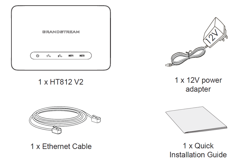
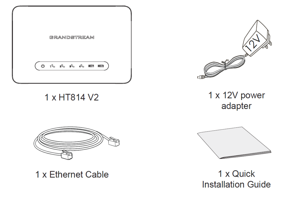

HT81x V2 Ports Description
The following figure describes the different ports on the back panel of the HT81x V2.

Port | Description |
 | Power socket. Used to power HT812 V2 (12V) |
 | NET1 port. Can be configured as LAN or WAN port on the HT812 V2. By default, it is considered a WAN port. |
 | NET2 port. Can be configured as LAN or WAN port on the HT812 V2. By default, it is considered a LAN port. |
 | FXS ports to connect analog phones / fax machines to HT812 V2 using RJ11 telephone cable. |
 | Factory reset button. Press for 7 seconds to reset to factory default settings. |

Port | Description |
| | Power socket. Used to power HT814 V2 (12V) |
| | NET1 port. Can be configured as LAN or WAN port on the HT814 V2. By default, it is considered a WAN port. |
| | NET2 port. Can be configured as LAN or WAN port on the HT814 V2. By default, it is considered a LAN port. |
 | FXS ports to connect analog phones / fax machines to HT814 V2 using RJ11 telephone cable. |
| | Factory reset button. Press for 7 seconds to reset to factory default settings. |

Port | Description |
| | Power socket. Used to power HT818 V2 (12V) |
| | NET1 port. Can be configured as LAN or WAN port on the HT818 V2. By default, it is considered a WAN port. |
| | NET2 port. Can be configured as LAN or WAN port on the HT818 V2. By default, it is considered a LAN port. |
 | FXS ports to connect analog phones / fax machines to HT818 V2 using RJ11 telephone cable. |
| | Factory reset button. Press for 7 seconds to reset to factory default settings. |
Connecting the HT81x V2
The HT81x V2 can be connected via NET1 port or NET2 port, by default, NET1 is WAN (DHCP Client) and NET2 is LAN (DHCP Server).
Scenario 1: Connecting the HT81x V2 Using NET1 port
When connecting HT81x V2 using the NET1 port, it will act as a simple DHCP Client:
- Insert a standard RJ11 telephone cable into an FXS port and connect the other end of the telephone cable to a standard touch-tone analog telephone.
- Connect the NET1 port of the HT81x V2 to a router, switch or modem using an Ethernet cable.
- Insert the power adapter into the HT81x V2 and connect it to a wall outlet (make sure to respect the technical specifications of the power adapter used).
- The Power, NET1 and FXS LEDs will be solidly lit when the HT81x V2 is ready for use.
Scenario 2: Connecting the HT81x V2 Using NET2 port
When connecting the HT81x V2 using the NET2 port, it will act as a DHCP Server:
- Insert a standard RJ11 telephone cable into an FXS port and connect the other end of the telephone cable to a standard touch-tone analog telephone.
- Connect a computer or switch to the NET2 port of the HT81x V2 using an Ethernet Cable.
- Insert the power adapter into the HT81x V2 and connect it to a wall outlet and make sure to respect the technical specifications of the power adapter used.
- The Power, NET2 and FXS LEDs will be solidly lit when the HT81x V2 is ready for use.
HT81x V2 LEDs Pattern
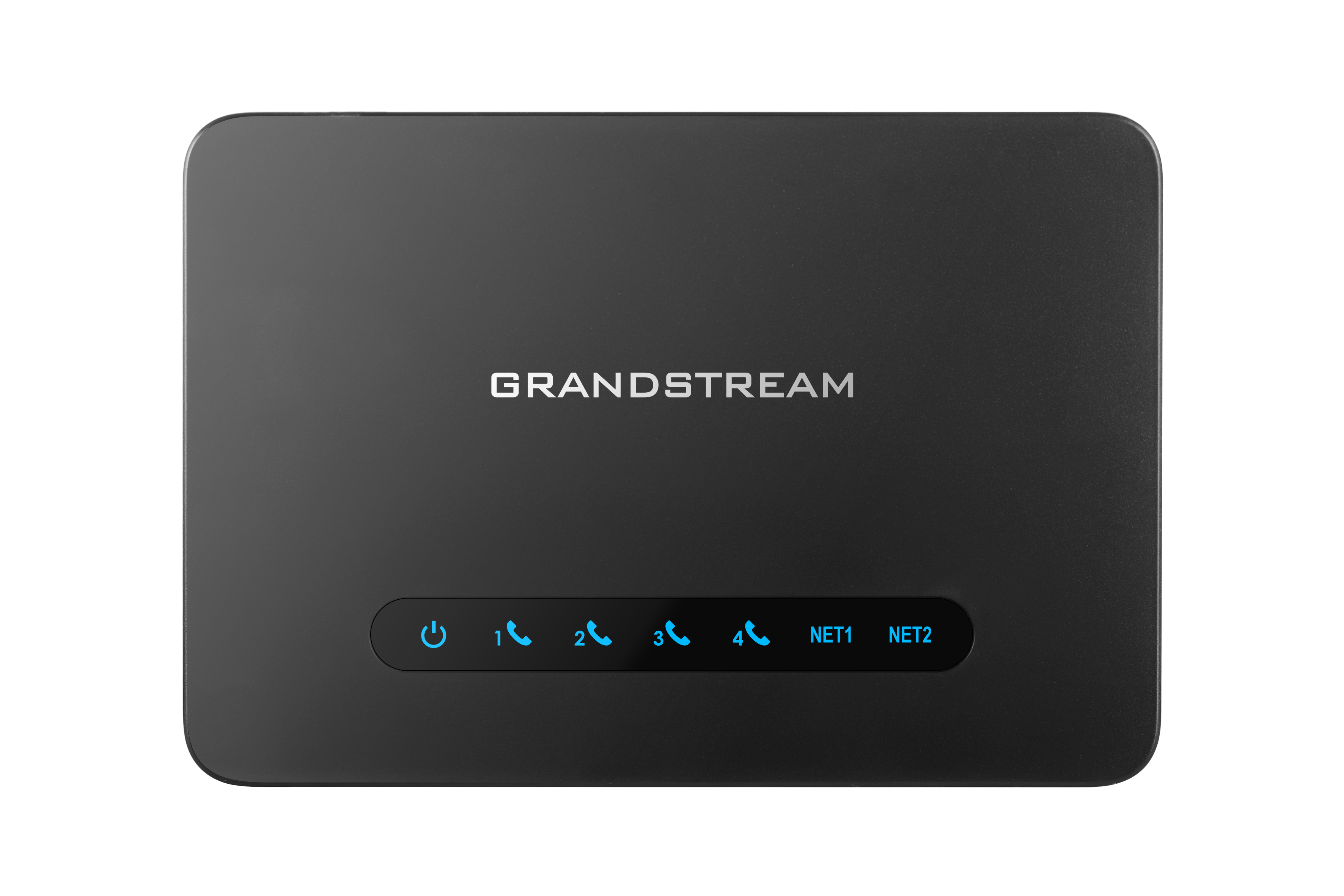
There are four (4) LED types that help you manage the status of your HT81x V2.

LED Lights | Status |
Power LED | The Power LED lights up when The HT812 V2 is powered on and it flashes when the HT812 V2 is booting up |
NET1 LED | The NET1 LED lights up when The HT812 V2 is connected to your network through the NET1 port. |
NET2 LED | The NET2 LED lights up when The HT812 V2 is connected to your network through the NET2 port. |
Phone LED 1-2 | The phone LEDs indicate status of the respective FXS port-phone on the back panel
|
HT812 V2 LEDs Pattern Description
LED Lights | Status |
Power LED | The Power LED lights up when The HT814 V2 is powered on and it flashes when the HT814 V2 is booting up |
NET1 LED | The NET1 LED lights up when The HT814 V2 is connected to your network through the NET1 port. |
NET2 LED | The NET2 LED lights up when The HT814 V2 is connected to your network through the NET2 port. |
Phone LED 1-4 | The phone LEDs indicate status of the respective FXS port-phone on the back panel
|

LED Lights | Status |
Power LED | The Power LED lights up when The HT818 V2 is powered on and it flashes when the HT818 V2 is booting up |
NET1 LED | The NET1 LED lights up when The HT818 V2 is connected to your network through the NET1 port. |
NET2 LED | The NET2 LED lights up when The HT818 V2 is connected to your network through the NET2 port. |
Phone LED 1- 8 | The phone LEDs indicate status of the respective FXS port-phone on the back panel
|
CONFIGURATION GUIDE
The HT81x V2 can be configured in one of two ways:
- The IVR voice prompt menu.
- The Web GUI is embedded on the HT81x V2 using the PC’s web browser.
Obtain HT81x V2 IP Address via Connected Analog Phone
HT81x V2 are by default configured to obtain the IP address from the DHCP server where the unit is located. To know which IP address is assigned to your HT81x V2, you should access the “Interactive Voice Response Menu” of your adapter via the connected phone and check its IP address mode.
Please refer to the steps below to access the interactive voice response menu:
- Use a telephone connected to the phone ports (FXS) of your HT81x V2.
- Press *** (press the star key three times) to access the IVR menu and wait until you hear “Enter the menu option “.
- Press 02 and the current IP address will be announced.
Understanding HT81x V2 Interactive Voice Prompt Response Menu
The HT81x V2 have a built-in voice prompt menu for simple device configuration which lists actions, commands, menu choices, and descriptions. The IVR menu works with any phone connected to the HT81x V2. Pick up the handset and dial “***” to use the IVR menu.
Menu | Voice Prompt | Options |
Main Menu | “Enter a Menu Option” | Press “*” for the next menu option Press “#” to return to the main menu Enter 01-05, 07,10, 12-17, 20, 47 or 99 menu options |
01 | “DHCP Mode”, “Static IP Mode” “PPPoE Mode“ | Press “9” to toggle the selection If using “Static IP Mode”, configure the IP address information using menus 02 to 05. If using “Dynamic IP Mode”, all IP address information comes from the DHCP server automatically after reboot. If using “PPPoE Mode”, configure PPPoE Username and Password from web GUI to get IP from your ISP. |
02 | “IP Address “ + IP address | The current WAN IP address is announced If using “Static IP Mode”, enter 12-digit new IP address. You need to reboot your HT812 V2/HT814 V2/HT818 V2 for the new IP address to take Effect. |
03 | “Subnet “ + IP address | Same as menu 02 |
04 | “Gateway “ + IP address | Same as menu 02 |
05 | “DNS Server “ + IP address | Same as menu 02 |
07 | Preferred Vocoder | Press “9” to move to the next selection in the list:
PCM U / PCM A iLBC G-726 G-723 G-729 OPUS G722
|
10 | “MAC Address” | Announces the MAC address of the unit.
Note: The device has two MAC addresses. One for the WAN port and one for the LAN port. The device MAC address announced is the address of LAN port. |
13 | Firmware Server IP Address | Announces current Firmware Server IP address. Enter 12-digit new IP address. |
14 | Configuration Server IP Address | Announces current Config Server Path IP address. Enter 12-digit new IP address. |
15 | Upgrade Protocol | Upgrade protocol for firmware and configuration update. Press “9” to toggle between TFTP/HTTP/HTTP /FTP/FTPS |
16 | Firmware Version | Announces Firmware version information. |
17 | Firmware Upgrade | Firmware upgrade mode. Press “9” to toggle among the following three options: Always check Check when pre/suffix changes Never upgrade |
20 | Certificate Type | Annouces certificate information. |
47 | “Direct IP Calling” | Enter the target IP address to make a direct IP call, after dial tone. |
86 | Voice Mail | Access to your voice mails messages. |
99 | “RESET” | Press “9” to reboot the device Enter MAC address to restore factory default setting (See Restore Factory Default Setting section) |
“Invalid Entry” | Automatically returns to main menu | |
“Device not registered” | This prompt will be played immediately after off hook If the device is not registered and the option “Outgoing Call without Registration” is in NO |
Voice Prompt Menu
Five success tips when using the voice prompt
- “*” shifts down to the next menu option and “#” returns to the main menu
- “9” functions as the ENTER key in many cases to confirm or toggle an option.
- All entered digit sequences have known lengths – 2 digits for the menu option and 12 digits for the IP address. For IP address, add 0 before the digits if the digits are less than 3 (i.e. – 192.168.0.26 should be keyed in like 192168000026. No decimal is needed).
- Key entry cannot be deleted but the phone may prompt an error once it is detected.
- Dial *98 to announce the extension number of the port.
Configuration via Web Browser
The HT81x V2 embedded Web server responds to HTTP GET/POST requests. Embedded HTML pages allow a user to configure the HT81x V2 through a web browser such as Google Chrome, Mozilla Firefox, and Microsoft’s IE.
- Microsoft Internet Explorer: version 10 or higher.
- Google Chrome: version 58.0.3 or higher.
- Mozilla Firefox: version 53.0.2 or higher.
- Safari: version 5.1.4 or higher.
- Opera: version 44.0.2 or higher.
Accessing the Web UI
The HT81x V2 can be connected via NET1 port or NET2 port, by default, NET1 is WAN (DHCP Client) and NET2 is LAN (DHCP Server).
- Via NET1 port
For the initial setup, the Web access is by default enabled when the device is using a private IP and disabled when using a public IP, and you cannot access the Web UI of your HT81x V2 until it’s enabled, the following steps will show you how to enable it via IVR.
- Power your HT81x V2 using a PSU with the right specifications.
- Connect your analog phone to the phone ports (FXS) of your HT81x V2.
- Press *** (press the star key three times) to access the IVR menu and wait until you hear “Enter the menu option “.
- Press 12, and the IVR menu will announce that the web access is disabled, press 9 to enable it.
- Reboot your HT81x V2 to apply the new settings.
Please refer to the steps below if your HT81x V2 is connected via the NET1 port:
- You may check your HT81x V2 IP address using the IVR on the connected phone.
Please see Obtain the HT81x V2 IP address via the connected analog phone
- Open the web browser on your computer.
- Enter the HT81x V2’s IP address in the address bar of the browser.
- Enter the administrator’s password to access the Web Configuration Menu.
- Via NET2 port
Please refer to the steps below if your HT81x V2 is connected via NET2 port:
- Power your HT81x V2 using PSU with the right specifications.
- Connect your computer or switch directly to your HT81x V2 NET2 port.
- Open the web browser on your computer.
- Enter the default NET2 IP address (192.168.2.1) in the address bar of the browser.
- Enter the administrator’s password to access the Web Configuration Menu.
- Make sure to reboot your device after changing your settings to apply the new configuration.
Web UI Access Level Management
There are three access level for the login page:
User Level | User | Password | Web Pages Allowed |
End User Level | user | 123 | View all pages but can only modify basic settings |
Administrator Level | admin | random password located at the back of the unit | Browse all pages and modify all settings |
Viewer Level | viewer | viewer | View all pages but no changes allowed. |
Saving the Configuration Changes
After modifying any configuration parameters, users can save the changes by clicking on the Save button. Once the configuration is saved, an Apply button will appear at the top of the page to allow users to apply the changes.
Users can also directly click on the Save and Apply button for the configuration changes to be saved and applied.
Changing Admin Level Password
- Access your HT81x V2 web UI by entering its IP address in your favorite browser.
- Enter your admin password (default is the random password located at the back of the unit).
- Press Login to access your settings.
- Go to System Settings 🡪 Security Settings 🡪 User Info Management and enter the new admin password.
- Confirm the new admin password.
- Press Apply at the bottom of the page to save your new settings.

Changing User Level Password
- Access your HT81x V2 web UI by entering its IP address in your favorite browser.
- Enter your admin password (default is the random password located at the back of the unit).
- Press Login to access your settings.
- Go to System Settings 🡪 Security Settings 🡪 User Info Management and enter the new end-user password.
- Confirm the new end-user password.
- Press Apply at the bottom of the page to save your new settings.

Changing Viewer Password
- Access your HT81x V2 web UI by entering its IP address in your favorite browser.
- Enter your admin password (default is the random password located at the back of the unit).
- Press Login to access your settings.
- Go to System Settings 🡪 Security Settings 🡪 User Info Management and enter the new viewer password.
- Confirm the new viewer password.
- Press Apply at the bottom of the page to save your new settings.

Changing HTTP Web Port
- Access your HT81x V2 web UI by entering its IP address in your favorite browser.
- Enter your admin password (default is the random password located at the back of the unit).
- Press Login to access your settings.
- Go to System Settings 🡪 Security Settings🡪 Web/SSH Access.
- Make sure that the Web Access Mode is set to HTTP.
- Change the current port to your desired/new HTTP port. Ports accepted are in the range [1-65535].
- Press Apply at the bottom of the page to save your new settings

Configuring HT81x V2 through Voice Prompts
As mentioned previously, The HT81x V2 have a built-in voice prompt menu for simple device configuration. Please refer to “Understanding HT81x V2 Interactive Voice Prompt Response Menu” for more information about IVR and how to access its menu.
- DHCP MODE
Select voice menu option 01 to enable HT81x V2 to use DHCP.
- STATIC IP MODE
Select voice menu option 01 to enable HT81x V2 to use STATIC IP mode, then use options 02, 03, 04, and 05 to set up IP address, Subnet Mask, Gateway, and DNS server respectively.
- PPPOE MODE
Select voice menu options 01 to allow the HT81x V2 to enable the PPPoE mode. PPPoE Username and Password should be configured from web GUI.
- FIRMWARE SERVER IP ADDRESS
Select voice menu option 13 to configure the IP address of the firmware server.
- CONFIGURATION SERVER IP ADDRESS
Select voice menu option 14 to configure the IP address of the configuration server.
Select menu option 15 to choose firmware and configuration upgrade protocol between TFTP, HTTP, HTTPS, FTP, and FTPS.
- FIRMWARE UPGRADE MODE
Select voice menu option 17 to choose firmware upgrade mode among the following three options:
1) Always check, 2) check when pre/suffix changes, and 3) never upgrade.
- WAN PORT WEB ACCESS
Select voice menu option 12 to enable/disable web access from the WAN port. Press 9 in this menu to toggle between enable / disable. The default is disabled.
Register a SIP Account
The HT81x V2 support Profiles that can configure two SIP servers,
Please refer to the following steps in order to register your accounts via web user interface.
- Access your HT81x V2 web UI by entering its IP address in your favorite browser.
- Enter your admin password (default: found on the sticker on the back of the unit).
- Press Login to access your settings.
- Go to Profile 1/ Profile 2 web pages and set the following:
- Account Active to Yes.
- Primary SIP Server field with your SIP server IP address or FQDN.
- Failover SIP Server with your Failover SIP Server IP address or FQDN. Leave empty if not available.
- Outbound Proxy: Set your Outbound Proxy IP Address or FQDN. Leave empty if not available.

- Go to FXS Port web page and set the following
- SIP User ID: Under Ports Web Page , Enter the SIP User ID User account information, provided by VoIP service provider (ITSP). Usually in the form of digit similar to phone number or actually a phone number.
- Authenticate ID: SIP service subscriber’s Authenticate ID used for authentication. Can be identical to or different from SIP User ID.
- Authenticate Password: SIP service subscriber’s account password to register to SIP server of ITSP. For security reasons, the password will field will be shown as empty.
- Name: Any name to identify this specific user.
- Press Apply at the bottom of the page to save your configuration.

After applying your configuration, your account will register to your SIP Server, you can verify if it has been correctly registered with your SIP server from your HT81x V2 web interface under Status 🡪 Port Status 🡪 Registration (If it displays Registered, it means that your account is fully registered, otherwise it will display Not Registered so in this case you must double check the settings or contact your provider).

Rebooting HT81x V2 Remotely
Press the “Reboot” button at the bottom of the configuration menu to reboot the ATA remotely. The web browser will then display a message window to confirm that reboot is underway. Wait 30 seconds to log in again
CALL FEATURES
The HT81x V2 support all the traditional and advanced telephony features.
Key | Call Features |
*02 | Forcing a Codec (per call) *027110 (PCMU), *027111 (PCMA), *02723 (G723), *02729 (G729), *027201 (iLBC), *02722 (G722). |
*03 | Disable LEC (per call) Dial “*03” +” number”. No dial tone is played in the middle. |
*16 | Enable SRTP |
*17 | Disable SRTP |
*18 | Enable SRTP per call. Meaning it’s only valid for the current call. |
*19 | Disable SRTP per call. Meaning it’s only valid for the current call. |
*30 | Block Caller ID (for all subsequent calls) |
*31 | Send Caller ID (for all subsequent calls) |
*47 | Direct IP Calling. Dial “*47” + “IP address”. No dial tone is played in the middle. |
*50 | Disable Call Waiting (for all subsequent calls) |
*51 | Enable Call Waiting (for all subsequent calls) |
*67 | Block Caller ID (per call). Dial “*67” +” number”. No dial tone is played in the middle. |
*82 | Send Caller ID (per call). Dial “*82” +” number”. No dial tone is played in the middle. |
*69 | Call Return Service: Dial *69 and the phone will dial the last incoming phone number received. |
*70 | Disable Call Waiting (per call). Dial “*70” +” number”. No dial tone is played in the middle. |
*71 | Enable Call Waiting (per call). Dial “*71” +” number”. No dial tone is played in the middle |
*72 | Unconditional Call Forward: Dial “*72” and then the forwarding number followed by “#”. Wait for dial tone and hang up. (dial tone indicates successful forward) |
*73 | Cancel Unconditional Call Forward. To cancel “Unconditional Call Forward”, dial “*73”, wait for dial tone, then hang up. |
*74 | Enable Paging Call: Dial “*74” and then the destination phone number you want to page. |
*77 | Enable set Offhook Auto-Dial. |
*78 | Enable Do Not Disturb (DND): When enabled all incoming calls are rejected. |
*79 | Disable Do Not Disturb (DND): When disabled, incoming calls are accepted. |
*87 | Blind Transfer |
*90 | Busy Call Forward: Dial “*90” and then the forwarding number followed by “#”. Wait for dial tone then hang up. |
*91 | Cancel Busy Call Forward. To cancel “Busy Call Forward”, dial “*91”, wait for dial tone, then hang up. |
*92 | Delayed Call Forward. Dial “*92” and then the forwarding number followed by “#”. Wait for dial tone then hang up. |
*93 | Cancel Delayed Call Forward. To cancel Delayed Call Forward, dial “*93”, wait for dial tone, then hang up |
*98 | Enable to play the registration ID. |
Flash/ Hook | Toggles between active call and incoming call (call waiting tone). If not in conversation, flash/hook will switch to a new channel for a new call. |
# | Pressing pound sign will serve as Re-Dial key. |
HT81x V2 Call Features
CALL OPERATIONS
Placing a Phone Call
To make the outgoing calls using your HT81x V2
- Pick up the handset of the connected phone.
- Dial the number directly and wait for 4 seconds (Default “No Key Entry Timeout”); or
- Dial the number directly and press # (“Use # as dial key” must be configured in web configuration).
Examples:
- Dial an extension directly on the same proxy, (e.g. 1008), and then press the # or wait for 4 seconds.
- Dial an outside number (e.g. (626) 666-7890), first enter the prefix number (usually 1+ or international code) followed by the phone number. Press # or wait for 4 seconds. Check with your VoIP service provider for further details on prefix numbers.
Note:
When placing the analog phone that is connected to the FXS port off hook, the dial tone will be played even if the sip account is not registered. If users prefer the busy tone to be played instead, the following configuration need to be made:
- “Play Busy Tone When Account is unregistered” need to be set to YES under advanced settings.
- “Outgoing call without registration” needs to be set to NO under Profile x settings.
Direct IP Calls
Direct IP calling allows two parties, that is, an FXS Port with an analog phone and another VoIP Device, to talk to each other in an ad hoc fashion without a SIP proxy.
Elements necessary to complete a Direct IP Call:
- Both HT81x V2 and other VoIP devices have public IP addresses, or
- Both HT81x V2 and other VoIP devices are on the same LAN using private IP addresses, or
- Both HT81x V2 and other VoIP devices can be connected through a router using public or private IP addresses (with necessary port forwarding or DMZ).
The HT81x V2 support two ways to make Direct IP Calling:
Using IVR
- Pick up the analog phone, then access the voice menu prompt by dialing “***”.
- Dial “47” to access the direct IP call menu
- Enter the IP address after the dial tone and voice prompt “Direct IP Calling”.
Using Star Code
- Pick up the analog phone, then dial “*47”.
- Enter the target IP address.
Examples of Direct IP Calls:
a) If the target IP address is 192.168.0.160, the dialing convention is *47 or Voice Prompt with option 47, then 192*168*0*160, followed by pressing the “#” key if it is configured as a send key or wait 4 seconds. In this case, the default destination port 5060 is used if no port is specified
b) If the target IP address/port is 192.168.1.20:5062, then the dialing convention would be: *47 or Voice Prompt with option 47, then 192*168*0*160*5062 followed by pressing the “#” key if it is configured as a send key or wait for 4 seconds.
Call Hold
You can place a call on hold by pressing the “flash” button on the analog phone (if the phone has that button).
Press the “flash” button again to release the previously held Caller and resume the conversation. If no “flash” button is available, use “hook flash” (toggle on-off hook quickly). You may drop a call using hook flash.
Call Waiting
The call waiting tone (3 short beeps) indicates an incoming call if the call waiting feature is enabled.
To toggle between incoming call and current call, you need to press the “flash” button when the first call is placed on hold.
Press the “flash” button to toggle between the active calls.
Call Transfer
Blind Transfer
Assume that the call is established between phone A and phone B are in conversation. Phone A wants toblind transfer phone B to phone C:
- On the phone A presses FLASH to hear the dial tone.
- The phone A dials *87, then dials caller C’s number, and then # (or wait for 4 seconds)
- Phone A will hear the dial tone. Then, A can hang up.
Attended Transfer
Assume that the call is established between phone A and phone B are in conversation. Phone A wants to attend transfer phone B to phone C:
- On the phone A presses FLASH to hear the dial tone.
- Phone A dials the phone C’s number, followed by # (or wait for 4 seconds).
- If phone C answers the call, phones A and C are in conversation. Then A can hang up to complete the transfer.
- If phone C does not answer the call, phone A can press “flash” to resume the call with phone B.
3-Way conferencing
The HT81x V2 supports Bellcore style 3-way Conference. To perform the 3-way conference, we assume that the call is established between phone A and phone B are in conversation. Phone A (HT81x V2) wants to bring third phone C into the conference:
- Phone A presses FLASH (on the analog phone, or Hook Flash for old model phones) to get a dial tone.
- Phone A dials C’s number then # (or wait for 4 seconds).
- If phone C answers the call, then A presses FLASH to bring B and C into the conference.
- If phone C does not answer the call, phone A can press FLASH back to talk to phone B.
- If phone A presses FLASH during the conference, phone C will be dropped out.
- If phone A hangs up, the conference will be terminated for all three parties when the configuration “Transfer on Conference Hang up” is set to “No”. If the configuration is set to “Yes”, A will transfer B to C so that B and C can continue the conversation.
Call Return
To call back the latest incoming number.
- Pick up the handset of the connected phone (Off-hook).
- After hearing the dial tone, input “*69”.
- Your phone will automatically call back the latest incoming number.
Inter-Port Calling
In some cases, a user may want to make phone calls between the phones connected to multiple ports of the same HT81x V2 when it is used as a standalone unit, without the use of a SIP server. In such cases, users will still be able to make inter-port calls by using the IVR feature.
On the HT81x V2 inter-port calling is achieved by dialing ***7X (X is the port number). For example, the user connected to port 1 can be reached by dialing *** and 71.
Voice Mail
VM Notification
The HT81x V2 indicates new voice mail messages using Phone LEDs and Stutter Tone.
The Phone LEDs on HT81x V2 will start blinking slowly when a new voicemail message is available on the corresponding account.
A stutter tone will be played at first few seconds, followed by the dial tone when picking up the handset.
Note: New VM messages can also be indicated by LED blink, screen display, etc, if they are supported on connected analog phones.
Accessing VM
To retrieve the new voice mail messages received, please refer to the following steps:
- Pick up the handset of the connected phone (stutter tone will be played).
- Press *** (press the star key three times) to access the IVR menu and wait until you hear “Enter the menu option “.
- Press 86 and enter your configured password (if exist) to access your voice mail menu.
Flash Digit Control
If the option Flash Digit Control is enabled on the web UI, call operations will require different steps as follows:
Flash Digit Call Hold
Assume that the call is established between phone A and B.
- Phone A received a call from C, then it held B to answer C.
- Press the “Flash + 1” to hang up the current call (A – C) and resume the call on hold (B).
- Or press “Flash + 2” to hold the current call (A – C) and resume the call on hold (B).
Flash Digit Attended transfer
Assume that the call is established between phone A and B. Phone A wants to attend transfer phone B to phone C:
- On the phone A presses FLASH to hear the dial tone.
- Phone A dials the phone C’s number, followed by # (or wait for 4 seconds).
- If phone C answers the call, phones A and C are in conversation. Then A can press “Flash + 4” to complete the transfer. Alternatively, if Flash Digit Control is set to “Yes with Attended Transfer Upon Onhook”, A can simply place the handset on-hook to complete the transfer.
Flash Digit 3-Way Conferencing
Assume that the call is established, and phones A and B are in conversation. Phone A(HT81x V2) wants to bring the third phone C into the conference:
- Phone A presses Flash (on the analog phone, or Hook Flash for old model phones) to get a dial tone.
- Phone A dials C’s number then # (or wait for 4 seconds).
- When phone C answers the call, then A can press “Flash +3” to bring B and C into the conference.
NAT Settings
If you plan to keep the HT81x V2 within a private network behind a firewall, we recommend using a STUN Server. The following three settings are useful in the STUN Server scenario:
- STUN Server (under advanced settings webpage) Enter a STUN server IP (or FQDN) that you may have, or look up a free public STUN Server on the internet and enter it on this field. If using a public IP, keep this field blank.
- Use Random SIP/RTP Ports (under the advanced settings webpage). This setting depends on your network settings. Generally, if you have multiple IP devices under the same network, it should be set to Yes. If using a public IP address, set this parameter to No.
- NAT traversal (under the FXS web page), set this to Yes when the gateway is behind a firewall on a private network.
DTMF Methods
The HT81x V2 support the following DTMF modes:
• DTMF in-audio
• DTMF via RTP (RFC2833)
• DTMF via SIP INFO
Set the priority of DTMF methods according to your preference. This setting should be based on your server DTMF setting.
Preferred Vocoder (Codec)
The HT81x V2 support following voice codecs. On Profile pages, choose the order of your favorite codecs:
- PCMU/A (or G711µ/a)
- G729 A/B
- G723.1
- G726
- iLBC
- OPUS
- G722
UPGRADING AND PROVISIONING
The HT81x V2 can be upgraded via TFTP/HTTP/HTTPS/FTP/FTPS by configuring the URL/IP Address for the TFTP/HTTP/HTTPS/FTP/FTPS server and selecting a download method. Configure a valid URL for TFTP, HTTP/HTTPS, or FTP/FTPS; the server name can be an FQDN or IP address.
Examples of valid URLs:
- firmware.grandstream.com
- fw.ipvideotalk.com/gs
Firmware Upgrade procedure
Please follow the steps below to upgrade the firmware version of your HT81x V2:
- Access your HT81x V2 UI by entering its IP address in your favorite browser.
- Enter your admin password (default: found on the sticker on the back of the unit).
- Press Login to access your settings.
- Go to the Maintenance 🡪 Upgrade 🡪 Firmware page and enter the IP address or the FQDN for the upgrade server in the “Firmware Server Path” field and choose to upgrade via TFTP, HTTP/HTTPS, or FTP/FTPS.
- Update the change by clicking the “Save and Apply” button at the bottom of the page. Then, “Reboot” or power cycle the HT81x V2 to update the new firmware.

Upgrading via Local Directory
- Download the firmware file from the Grandstream website
- Unzip it and copy the file into a folder on your PC
- From the HT81x V2 web interface Maintenance 🡪 Upgrade 🡪 Firmware you can browse your hard drive and select the folder you previously saved the file.
- Click “Upload” and wait few minutes until the new program is loaded.
Upgrading via Local TFTP/HTTP/HTTPS/FTP/FTPS Servers
For users who would like to use remote upgrading without a local TFTP/HTTP/HTTPS/FTP/FTPS server, Grandstream offers a NAT-friendly HTTP server. This enables users to download the latest software upgrades for their devices via this server. Please refer to the webpage:
https://www.grandstream.com/support/firmware
Alternatively, users can download, for example, a free TFTP or HTTP server and conduct a local firmware upgrade. A free Windows version TFTP server is available for download from:
https://www.solarwinds.com/products/freetools/free_tftp_server.aspx
https://pjo2.github.io/tftpd64/
Instructions for local firmware upgrade via TFTP:
- Unzip the firmware files and put all of them in the root directory of the TFTP server.
- Connect the PC running the TFTP server and the phone to the same LAN segment.
- Launch the TFTP server and go to the File menu🡪Configure🡪Security to change the TFTP server’s default setting from “Receive Only” to “Transmit Only” for the firmware upgrade.
- Start the TFTP server and configure the TFTP server in the phone’s web configuration interface.
- Configure the Firmware Server Path to the IP address of the PC.
- Save and apply the changes, and reboot the HT81x V2.
End users can also choose to download a free HTTP server from https://httpd.apache.org/ or use a Microsoft IIS web server.
Firmware and Configuration File Prefix and Postfix
Firmware Prefix and Postfix allow the device to download the firmware name with the matching Prefix and Postfix. This makes it possible to store all the firmware with different versions in one single directory. Similarly, Config File Prefix and Postfix allow the device to download the configuration file with the matching Prefix and Postfix. Thus, multiple configuration files for the same device can be stored in one directory.

Managing Automatic Upgrade
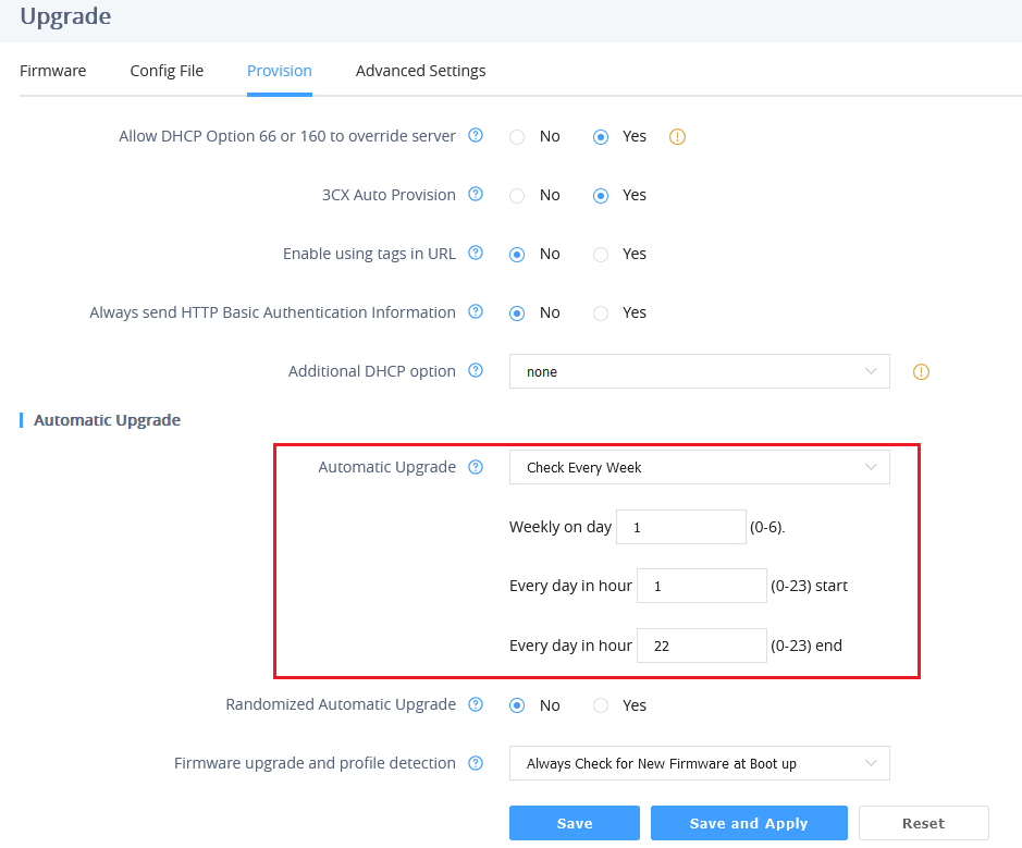
When “Automatic Upgrade” is set “Check”, the auto check will be done in the minute specified in this field. If set to “Every day in hour (0-23)”,the Service Provider can use P193 (Auto Check Interval) to have the devices do a daily check at the hour set in this field with either Firmware Server or Config Server. If set to “Weekly on day (0-6)”, the auto check will be done on the day specified in this field. This allows the device periodically to check if there are any new changes that need to be taken on a scheduled time. By defining different intervals in P193 for different devices, Server Provider can spread the Firmware or Configuration File download in minutes to reduce the Firmware or Provisioning Server load at any given time
Managing Device using GDMS Cloud
The GDMS Device Management System is a cloud solution from Grandstream that facilitates the provisioning and management of Grandstream devices, including the HT8xx ATAs.
The platform enables users to centralize the control and management of multiple HT8xx devices, deployed across various locations, on a single interface. It provides functionalities to upgrade, add, configure, and monitor HT8xx V2 devices from one centralized dashboard.
For more details on the supported HT8xx V2 models and their deployment to the GDMS platform, refer to the following guide: GDMS Unified Communications – User Guide.
If you don’t have a GDMS account yet, visit the following website to create one: GDMS.
Configuration File Download
Grandstream SIP Devices can be configured via the Web Interface as well as via a Configuration File (binary or XML) through TFTP, HTTP/HTTPS, or FTP/FTPS. The Config Server Path is the TFTP, HTTP/HTTPS, or FTP/FTPS server path for the configuration file. It needs to be set to a valid URL, either in FQDN or IP address format. The Config Server Path can be the same or different from the Firmware Server Path.
A configuration parameter is associated with each particular field in the web configuration page. A parameter consists of a Capital letter P and 1 to 5 (Could be extended in the future) digit numbers. i.e., P30 is associated with the “NTP Server” in the Web GUI🡪System Settings🡪Time and Language🡪Time Zone🡪NTP Server. For a detailed parameter list, please refer to the corresponding firmware release configuration template.
When the HT81x V2 boots up or reboots, it will send a request to download the xml file named “cfgxxxxxxxxxxxx.xml” followed by the binary file named “cfgxxxxxxxxxxxx”, where “xxxxxxxxxxxx” is the MAC address of the phone, i.e., “cfg000b820102ab” and “cfg000b820102ab.xml”. If the download of the “cfgxxxxxxxxxxxx.xml” file is not successful, the provision program will download a generic cfg<Model>.xml file and then download cfg.xml. The configuration file name should be in lower-case letters.
HT818 supports DHCP option 67, allowing the provision of a custom name for the provisioning file. If DHCP option 67 is used, the following file download sequence will be applied:
Step 1: <option 67 bootfile>
Step 2: cfg<MAC>.xml →cfg<MAC>→cfg<Model>.xml →cfg.xml
Notes:
1. The Only acceptable Config file formats to be used when provisioning are XML or binary.
2. Make sure the MAC header on the Config file is the provisioned device’s MAC address or you can remove the header completely.
3. When the <option 67 bootfile> is downloaded from the server, the cfg<MAC>.xml is not requested.
For more details on XML provisioning, please refer to:
https://documentation.grandstream.com/knowledge-base/sip-device-provisioning-guide/
Configuration and Firmware Upgrade through Resync SIP NOTIFY
HT81x V2 supports triggering firmware and configuration upgrade using Resync SIP NOTIFY. The event:resync NOTIFY allows the device to re-synchronize its configuration by checking the provisioning server to download any updates.
Below is an example of a resync SIP NOTIFY:
NOTIFY sip:device@domain.com SIP/2.0
Via: SIP/2.0/UDP 10.0.0.5:5060;branch=z9hG4bK-d4f2-9a75
Max-Forwards: 70
From: "Provisioning Server" <sip:provisioning@domain.com>;tag=prov-server
To: <sip:device@domain.com>;tag=device-987654
Call-ID: 987654xyz321
CSeq: 12345 NOTIFY
Event: resync
Content-Type: application/simple-message-summary
Content-Length: 45
CA Bundle Manifest
CA (Certification Authority) Bundle Manifest is a collection of trusted security certificates used to verify the authenticity of websites or services. It helps ensure secure and encrypted connections by confirming the identity of the remote server and protecting against unauthorized access and data interception.
you can access the CA Bundle Manifest by clicking on the bottom corner of the web page, as displayed in the screenshot below:

This will redirect you to a web page displaying a list of certification names and details, with their corresponding expiration dates:

RESTORE FACTORY DEFAULT SETTINGS
There are three (3) methods for resetting your unit:
Using the Reset Button
To reset default factory settings using the reset button, please follow the steps above:
- Unplug the Ethernet cable.
- Locate the reset hole on the back panel of your HT81x V2.
- Insert a pin in this hole and press for about 7 seconds.
- Take out the pin. All unit settings are restored to factory settings
Using the IVR Command
Reset default factory settings using the IVR prompt:
- Dial “***” for voice prompt.
- Enter “99” and wait for “the reset” voice prompt.
- Enter the encoded MAC address (Look below on how to encode the MAC address).
- Wait 15 seconds, and the device will automatically reboot and restore factory settings.
Encode the MAC Address
- Locate the MAC address of the device. It is the 12-digit HEX number on the bottom of the unit.
- Key in the MAC address. Use the following mapping:
Key | Mapping |
0-9 | 0-9 |
A | 22 (press the “2” key twice, “A” will show on the LCD) |
B | 222 |
C | 2222 |
D | 33 (press the “3” key twice, “D” will show on the LCD) |
E | 333 |
F | 3333 |
MAC Address Key Mapping
For example, if the MAC address is 000b8200e395, it should be keyed in as “0002228200333395”.
Reset from Web Interface (Reset Type)
- Access your HT81x V2 UI by entering its IP address in your favorite browser.
- Enter your admin password (default: found on the sticker on the back of the unit).
- Press Login to access your settings.
- Go to Maintenance 🡪 Restore Factory 🡪 Reset Type.
- Press the Reset button(after selecting the reset type).
• Full Reset: This will make a full reset
• ISP Data: This will reset only the basic settings, like IP mode, PPPoE and Web port
• VOIP Data Reset: This will reset only the data related to a service provider, like SIP server, SIP user ID, provisioning, and others.
Reset using SIP NOTIFY
- Access your HT81x V2 UI by entering its IP address in your favorite browser.
- Go to the Port Settings 🡪 Profile # page.
- Set “Allow SIP Factory Reset” to “Yes”. (Default is No)
- Once a SIP NOTIFY with “event: reset” is received, the ATA will perform a factory reset.
CHANGE LOG
This section documents significant changes from previous versions of the admin guide for HT81x V2. Only major new features or major document updates are listed here. Minor updates for corrections or editing are not documented here.
Firmware Version 1.0.15.3
- No major changes.
Firmware Version 1.0.15.1
- No major changes.
Firmware Version 1.0.13.5
- Added support for the option “Yes with Attended Transfer Upon Onhook” in Flash Digit Control. [Flash Digit Attended Transfer]
Firmware Version 1.0.11.4
- No major changes.
Firmware Version 1.0.9.4
- No major changes.
Firmware Version 1.0.9.3
- No major changes.
Firmware Version 1.0.7.5
- No major changes.
Firmware Version 1.0.5.10
- No major changes.
Firmware Version 1.0.5.9
- No major changes.
Firmware Version 1.0.5.7
- No major changes.
Firmware Version 1.0.5.5
- No major changes.
Firmware Version 1.0.5.4
- No major changes.
Firmware Version 1.0.5.3
- No major changes.
Firmware Version 1.0.3.10
- No major changes.
Firmware Version 1.0.3.8
- No major changes.
Firmware Version 1.0.3.5
- Added support for firmware upgrade via resync SIP Notify. [Configuration and Firmware Upgrade through Resync SIP NOTIFY]
Firmware Version 1.0.1.14
- This is the initial Firmware.